Idiot's Guides: 3D Printing (2015)
PART 4
3D Modeling
PROJECT 8
Reverse Engineering a Useful Part
Project Time: 30 minutes
This project will involve reverse engineering a part from around your house: an electrical socket cover. Why a socket cover? Because everyone has one in their home, so it’s something everyone will be able to follow along with. I’ll be modeling a standard U.S. socket cover, but the process should be pretty similar for other kinds of sockets in other countries.
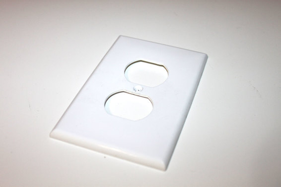
A standard U.S. electrical socket cover.
The idea here is that you’ll be learning how to take measurements from the original part. So I won’t be providing you with the actual dimensions I used in most cases. Instead, you’ll be in charge of coming up with the measurements yourself.
Create a New Part and Extrude the Body
Open up your CAD software and create a new part. As always, I personally prefer to work with millimeters. But you’re welcome to use inches if you prefer, especially since you’ll be taking the measurements yourself.
You can start by modeling a simple rectangle to get the overall body of the cover done. You want to extrude off of the front plane, so it lies flat on print bed. Just measure the length and width of the cover to draw a rectangle, and make sure it’s centered on the origin. Next, measure the overall thickness of the cover for the extrusion thickness.
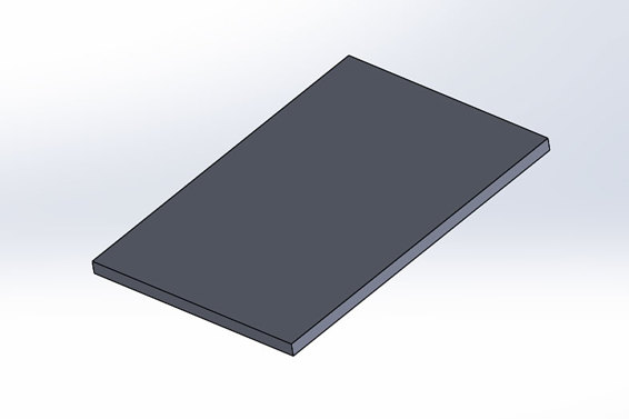
Model a simple rectangular solid for the body of the cover.
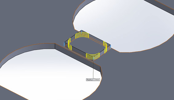
Fillet the Edges
As I’m sure you’ve noticed, the outside edges of the socket cover are rounded. This is really just a cosmetic feature, but it’s one which is easy to add.
You simply need to fillet the top outside edges of the cover. Because it’s just cosmetic, you don’t need to get the radius of the fillet perfect; just pick a radius that looks right to you.
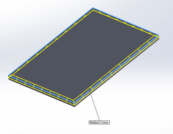
Fillet the top edges to improve the aesthetics. As you can see here, I used a radius of 3mm, but the radius you use is entirely up to you.
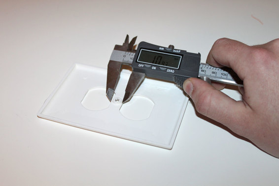
Shell the Cover
Unlike the fillets, this feature is important to the functionality of the part. You’ll need to use the shell command in your software to essentially hollow out the cover. To do this, you first need to measure the thickness of the plastic that makes up the cover (not the overall thickness).

Measure the thickness of the plastic that makes up the cover.
Once you know the thickness of the plastic, you can then create the shell feature. To do this, you need to specify that thickness you measured, as well as the face you’d like to delete. In this case, you want to delete the back face of the cover (opposite of the fillets).
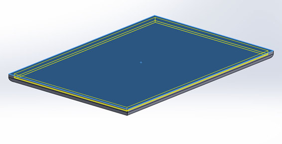
Create the shell by specifying the thickness and which face you’d like to remove.
Cut One Socket Opening
Now it’s time to go add an extruded cut for the opening for the actual socket. If you look closely, you’ll see that it’s actually a relatively simple cutout. It’s made up of two straight lines that are connected by two arcs (at least on the U.S. socket).
You can model this in a number of different ways, but I recommend you start with the two straight lines. Draw them based on their length and distance from the top (they should be centered from left to right).
Next, you can draw the arcs. You know their endpoints (the straight lines), so you just need to figure out the midpoints of the arcs. You can do that by measuring the width at the widest point and drawing a construction line centered between the two straight lines to represent it. You can then just draw an arc with its endpoints on the straight lines, and its midpoint on the end of the construction line.
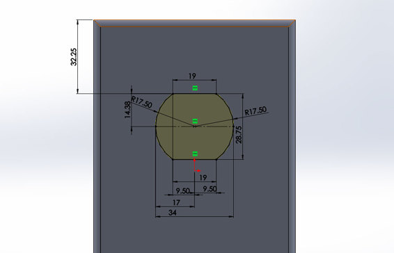
Cut the opening for the electrical socket.
Mirror the Socket Opening
The openings for the electrical sockets are symmetrical, so all you’ll need to do to make the second opening is to mirror the first. Select the mirror command in your software and use the top plane as the mirror plane, with the first opening as the feature to mirror.
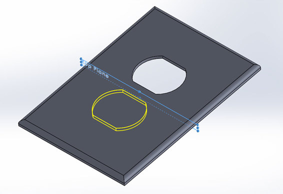
Mirror the first socket opening to create the second.
Create the Screw Hole Support
On this particular socket cover, there is additional material on the back where the screw hole goes through. This is to add support for the screw, where it pushes against the outlet mounted on the wall. There are also some ribs on the back, but they’re probably not integral to the function of the part.
This is a pretty simple feature—just a rectangular support with rounded corners. To begin, measure the length, width, and depth of the support using an actual socket cover.
![]()
HOT TIP
Measuring the width and length are easy enough, but the depth is a little harder. If your calipers have a depth gauge at the end, this is one feature where it will come in handy. If you not, you’ll just have measure it as best as you can.
Measure the length, width, and depth of the support.
The corners of the support are rounded. However, the exact radius almost definitely isn’t going to affect how well the part functions. So just estimate the radius of the fillets as best as you can.
Add fillets to round the corners of the support.
Add the Screw Hole
The screw hole on this part is countersunk to allow the screw to sit flush (or almost flush) with the surface of the cover. To make this, start by measuring the diameter of the actual hole (this is easiest to do from the back) and cut that.
Finally, you need to add the countersink. This can easily be created by using the chamfer command in your software on the edge of the hole. However, you need to know two things: chamfer distance and angle. The distance is easy enough; all you have to do is measure the diameter at the top of the countersink and divide it by 2. The angle will be harder to measure, though. However, 45° is a pretty safe assumption, because it’s commonly used for countersunkscrew holes.
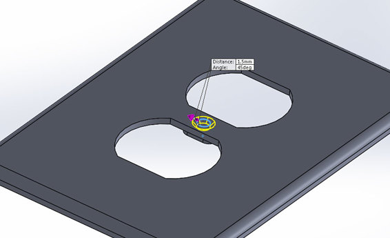
A chamfer can be used to add the countersink.
Export the .STL File and Print
The best way to determine how well you measured and modeled the part is to actually print it out and try it. You can export it the same way as any other part, and I recommend using the highest-quality settings. When you print it, you shouldn’t need to use any supports, and you can probably get away with a moderate infill (like 25 to 50 percent). Let the part cool before removing.
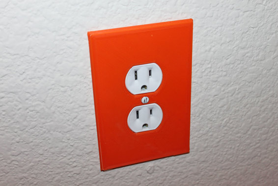
The finished cover mounted on the wall, and it fits correctly!
All materials on the site are licensed Creative Commons Attribution-Sharealike 3.0 Unported CC BY-SA 3.0 & GNU Free Documentation License (GFDL)
If you are the copyright holder of any material contained on our site and intend to remove it, please contact our site administrator for approval.
© 2016-2026 All site design rights belong to S.Y.A.