Canon EOS 70D: The Guide to Understanding and Using Your Camera (2014)
Chapter 15. The Set Up Menus
Set Up1

Figure 15-1. The Set Up1 tab
Select Folder
The EOS 70D has the ability to manage several different folders on the memory card. It will always start with a folder named 100CANON, but you can create additional folders by touching the Create Folder option (shown in Figure 15-3), or by selecting the Create Folder option and then pressing SET, followed by touching the OK icon, or by selecting OK and pressing SET again. The name of each new folder is a number (one number higher than the folder before it) with the letters “CANON” appended to it.
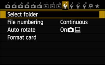
Figure 15-2. Selecting the Select Folder option
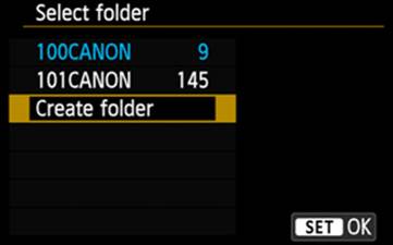
Figure 15-3. Choosing the Create Folder option
If you select a folder that contains recorded images, the right edge of the LCD Monitor will show thumbnail images of the first and last images in that folder, with the numeric portion of the folder name and the image number. For example, the number 100-0005 appears over the top thumbnail image in Figure 15-4. The 100 refers to the folder (100Canon) and the 0005 is the image number within that folder.
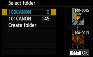
Figure 15-4. Selecting a folder
There is no way to use the camera to generate a specific folder name, but with the memory card displayed on a computer, you can use Windows Explorer (or the equivalent) to create specific folder names in the DCIM folder on the memory card. The three-digit prefix must be unique for each folder, regardless of the characters that follow the number, and must be in the range of 100 through 999. This allows you to identify the photo subjects you wish to segregate across folders; you can create folder names such as 123_Dogs, 372_Cats, 229_Cows, etc. Note that there can be no blanks in the folder name, and the underscore is the only special character allowed. Though shown in my examples, the underscore is not required in the folder name. Now you can use the Select Folder option to choose which folder will receive new images. This folder will remain selected as the current folder until you use Select Folder to choose another. If you format the memory card, then all folders are deleted and new images will be stored in the 100CANON folder created by the Format function.
File Numbering
The EOS 70D uses a four-digit number to uniquely identify images. The camera starts with image number 0001 and increases that value by one for each subsequent exposure. This four-digit number is appended to the four characters IMG_ for still images (both JPG and RAW) or MVI_ for movies to create the full eight-character file name that identifies the image in a computer.
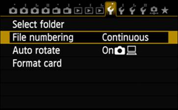
Figure 15-5. Selecting the File Numbering option
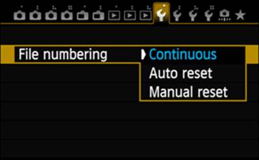
Figure 15-6. Choosing a File Numbering setting
If you select the File Numbering option in the Set Up1 menu, you can choose one of three settings:
Continuous will maintain the incremental numbering system regardless of what memory card is in the camera, and regardless of what folder is currently active. The slight disadvantage to this system is that if you change folders or memory cards, then revert back, you will have a discontinuous range of numbers in those folders or memory cards. However, that’s more than offset by the advantage of never losing an image because you had multiple images with the same four-digit image number.
Auto Reset will restart the numbering at 0001 if the camera detects a new or different memory card, or you create a new folder. I don’t encourage the use of this setting; it’s far too easy to copy files from one folder to another, and to lose one version of any files that have the same number.
Manual Reset is used to force the creation of a new folder and the resetting of the file number to 0001. I would like to have a means to disable commands such as this.
Auto Rotate
When we take a photo in portrait orientation, the Image Review will show us the capture using the full LCD Monitor if we continue to hold the camera in that portrait orientation. If you try to quickly rotate the camera to landscape orientation, the image review is terminated (automatic image rotation is supported in image playback, but not in image review). By default, the On setting that includes icons for both the camera and a computer monitor is active. When you use playback to review your images, those shot in portrait orientation will be rotated to appear right-side up in accordance with the camera in its normal horizontal orientation. This means the image must be resized to allow its full height to be displayed in the much smaller space of the LCD Monitor. Because I don’t try to use my camera in place of my computer for image enhancements, I have no problem selecting the On setting with just the computer monitor icon. That leaves the images unrotated in the camera (yes, I do have to rotate the camera to study the image in playback, but I then have a full-size image to work with on my computer). The image will be automatically rotated in the computer, which is quite handy when scouring through hundreds of images in Adobe Bridge or Lightroom. There may be some instances in which the Off setting is appropriate, but I’m not aware of them.
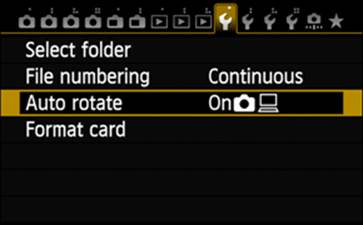
Figure 15-7. Selecting the Auto Rotate option
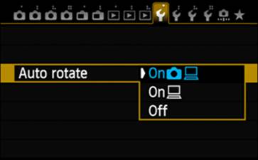
Figure 15-8. Choosing an Auto Rotate setting
Auto rotation works only with vertical images that were captured while Auto Rotation was on; turning Auto Rotation on for playback will not rotate those images captured when Auto Rotation was set to Off or to On/computer-only.
Format Card
Formatting is one of the essential tools used in digital cameras. It is designed to accomplish two significant tasks:
1) Delete everything from a memory card, even images that have been marked as protected, GPS log files, Print Order (DPOF) files, and all other files.
2) Create a data storage structure that conforms to the protocols used by the formatting camera.
Just because an SD card will fit in another manufacturer’s camera does not mean the camera uses a compatible set of data storage protocols. In fact, there is no assurance that one model of a manufacturer’s line of cameras will necessarily be compatible with all other cameras produced by that manufacturer. As a rule of thumb, do not indiscriminately swap memory cards between cameras unless they are the same model.
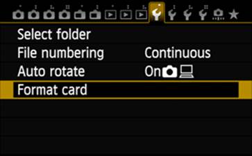
Figure 15-9. Selecting the Format Card option
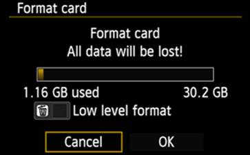
Figure 15-10. Confirming the Format Card choice
Along that same line, never use a computer to format a memory card for use in a camera. If this has been done, reformat the memory card in the camera before using that memory card.
Most of the currently produced cameras, including the EOS 70D, and most of today’s computers can handle memory cards up to 128 GB. However, use of File Allocation Table (FAT) technology is limited to 128 GB. Using a larger memory card would require the memory card manufacturer and the camera manufacturer to agree on a new technology. Reading very large memory cards on a stand-alone card reader attached to a computer would also require that the card reader be compatible with the new technology, as well as the computer. Canon has already stated that their implementation will use the exFAT (extended FAT) technology, which supports huge (by today’s standards) memory cards.
Eye-Fi memory cards contain software that must be copied to your computer before you format the Eye-Fi memory card.
Set Up2

Figure 15-11. The Set Up2 tab
Auto Power Off
Without power, this beautiful camera is a boat anchor; it can do nothing except hang heavily around your neck. For most of us, that power comes from one or more batteries. (The battery grip BG-E14 will actually carry two LP-E6 batteries.) To assist you in managing battery use, the camera can automatically shut down if you leave it unattended for the period of time indicated in the Auto Power Off menu.
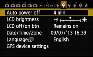
Figure 15-12. Selecting the Auto Power Off option
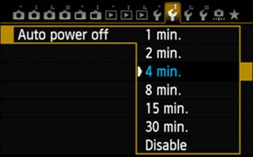
Figure 15-13. Choosing an Auto Power Off setting
The Auto Power Off option in the Set Up2 menu gives you various possible durations ranging from one minute to 30 minutes, and even provides a Disable setting that, when selected, will prevent the camera from turning the power off.
After the camera has been idle for the amount of time indicated, the power is not shut off completely, but the power consumption is greatly reduced. The camera does continue to monitor several buttons (the Shutter button, the Playback button, the MENU button, etc.). If one of those is pressed, the camera will turn back on.
When I replace the LP-E6 battery with the ACK-E6 AC adapter, I use the 30-minute setting. If I get distracted and leave the camera without shutting it down, it will shut down automatically after a half an hour.
LCD Brightness
Action shooters tend to rely on the LCD Panel or the viewfinder for most of their information, and some information is only available on the LCD Monitor. The LCD Brightness option, which can be fine-tuned to one of seven levels, will alter the appearance of that LCD display.
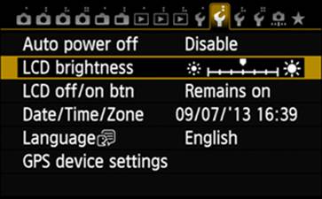
Figure 15-14. Selecting the LCD Brightness option
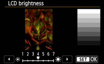
Figure 15-15. Choosing an LCD Brightness setting
Use the gray chart to the right of the image thumbnail as a guide in setting the brightness. If the top two white bars seem to merge into one wide bar, your setting is too bright. If the bottom two black bars seem to merge, your setting is too dark. If you’re using Live View while outside (or otherwise depending on improving the readability of the LCD Monitor), you may want to crank this setting up to seven.
The title of this option leaves room for the reader to infer that the LCD Panel would also be affected by any changes made in this option, but that is not the case; this option applies only to the LCD Monitor.
LCD Off/On Btn
I’m still trying to understand the advantage of this option. Its purpose is to allow you to specify whether the shooting functions panel and the electronic level screen, displayed by pressing the INFO button, should remain on until you press the Shutter button halfway, or until you press the Shutter button completely.
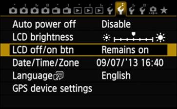
Figure 15-16. Selecting the LCD Off/On Btn option
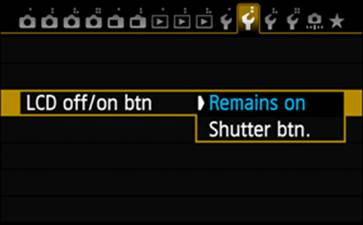
Figure 15-17. Choosing an LCD Off/On Btn setting
Date/Time/Zone
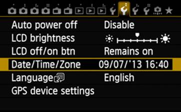
Figure 15-18. Selecting the Date/Time/Zone option
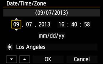
Figure 15-19. Configuring a Date/Time/Zone setting
The Date/Time/Zone option should be one of the first options you set. In fact, the camera should prompt you to enter date, time, and time-zone information, beginning with something like the screen shown in Figure 15-19, the first time it is turned on. I encourage you to look at the third line below the Date/Time/Zone title bar to determine which date convention is being used, and change it if it’s different from what you want. Using the touch feature, touch the text on that third line (by default, it will read “mm/dd/yy”), then touch the up or down arrow in the lower left corner of the LCD Monitor to select a different date convention. To change the date convention by using the Quick Control Dial or Multi-controller, move the gold-bordered box to enclose that information, and then press SET. Up and down arrows will be affixed to the gold border. Now use the Quick Control Dial or the Multi-controller to cycle through the available date conventions, noting the changes occurring on the first two lines. Once you’ve selected the date convention, press SET to register your choice.
Use the touch feature, the Quick Control Dial, or the Multi-controller to navigate to set the date and time. Again, a gold-bordered box will identify the selected value. If using the Quick Control Dial or Multi-controller, pressing SET will cause the up and down arrows to be appended to the gold border. Use these arrows or the arrows in the lower-left corner of the LCD Monitor to change that value. Press SET to register the value, and then navigate to the next value to be changed.
Below the date convention line there is a line that shows a city’s name, presumably a recognizable name that is conspicuous within a time zone. In Figure 15-19, that city is Los Angeles. When you’ve selected the city-name field, there will be a new line added at the top of the screen showing Time zone and a value based on displacement from Greenwich Mean Time, which—as shown in Figure 15-20—is +5:45 for Kathmandu. There are over 30 cities listed in the city-name field, which is strange since there are only 24 hours in the day and, presumably only 24 time zones. However, not all countries use a one-hour increment when establishing a new time zone. For example, The Chatham Islands are +12:45 ahead of Greenwich Mean Time, and Adelaide, Australia is +9:30 ahead of Greenwich Mean Time.
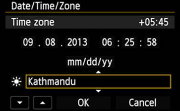
Figure 15-20. An example of unusual time zone differential
To the left of the city-name field is a small icon used to enable or disable daylight saving time. Select this icon and press SET to choose between the sun icon (representing daylight saving time) and the sun-OFF icon (representing no daylight saving time). The camera does not automatically reset the clock as daylight saving status changes.
Language
Everything we have seen in these numerous screen captures of menus has been in English. However, if there is another language you are more comfortable with, there is a possibility that the camera has a set of menus available in that language. In fact, the translation is not limited to menus, but includes almost everything the camera can display on the LCD Monitor. The Quick Control screen and the INFO information for camera shooting are not translated, and there may be a few other exceptions.
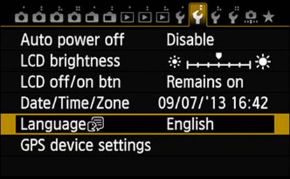
Figure 15-21. Selecting the Language option
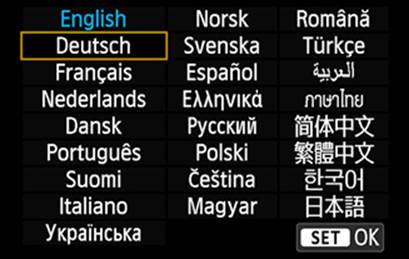
Figure 15-22. Choosing a menu language
As shown in Figure 15-23, there are terms (especially acronyms and initialisms such as GPS) for which there are no direct translations, so they appear in English.
In Figure 15-21, note the talking head icon just to the right of the word Language. The same icon appears in Figure 15-23. This can become very important when you inadvertently select a language you are not familiar with. If you recognize your error before leaving this menu, you can locate the Language option by the gold rectangle that identifies the current option. However, if you progress beyond that point before realizing you are working with the wrong language, you may need that icon to help you locate the correct option. Be aware that there are a few options that are not reset when you use the Clear All Camera Settings option in the Set Up4 menu, and Language is one of them.
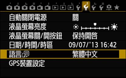
Figure 15-23. The Set Up2 menu in Simplified Chinese
GPS Device Settings
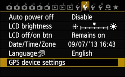
Figure 15-24. Selecting the GPS option
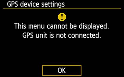
Figure 15-25. GPS information screen on the EOS 70D
Unlike the EOS 6D, the EOS 70D does not provide a built-in GPS feature. However, Canon sells the external GPS receiver GP-E2, which attaches to the EOS 70D’s hot shoe.
To use GPS with the EOS 70D, you need to select the GPS option on the Set Up2 tab and press SET. Follow the instructions that accompany the GP-E2 unit, starting on page 14 of the English language section.
Set Up3

Figure 15-26. The Set Up3 tab
Video System
If you are recording movies with this camera, you need to be aware of the television standards used by your country. In all of North America, most of Central and South America, and all of Japan and Taiwan, the NTSC (National Television System Committee) standard—using frame rates like 24, 30, and 60 frames per second—is used; elsewhere, the PAL (Phase Alternating Line) standard—using frame rates like 24, 25, and 50 frames per second—is used. SECAM (Sequential Color with Memory, used in France, Russia, large parts of Africa, and large parts of the Middle East) is not supported by the EOS 70D. Select the appropriate setting and press SET.
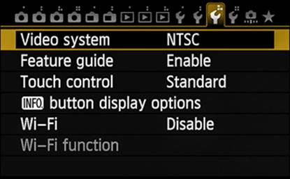
Figure 15-27. Selecting the Video System option
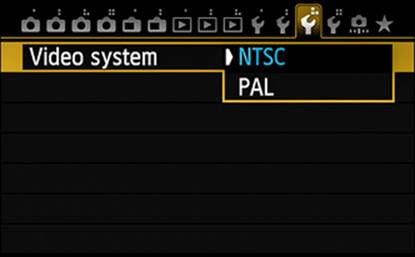
Figure 15-28. Choosing a Video System setting
Feature Guide
By default, this option is enabled. The Feature Guide displays a brief description of certain modes, functions, or options for the entity you select, and the description disappears as you proceed with the operation. That’s very nice initially, but a minor annoyance after a while; that’s the time to disable it.
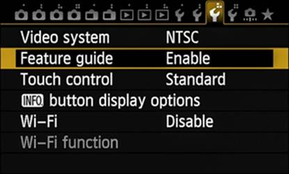
Figure 15-29. Selecting the Feature Guide option
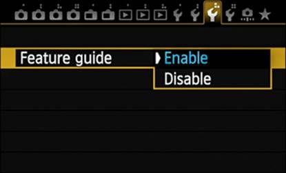
Figure 15-30. Choosing a Feature Guide setting
Touch Control
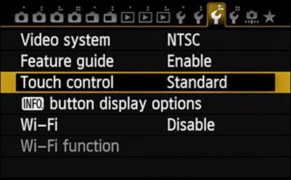
Figure 15-31. Selecting the Touch Control option
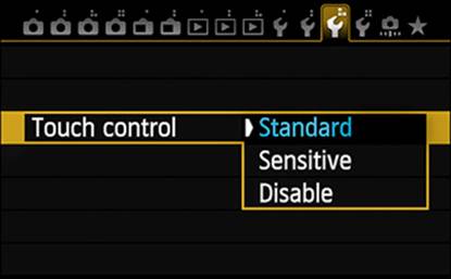
Figure 15-32. Choosing a Touch Control setting
The touch feature on the EOS 70D is controlled by this option. Though it offers a simplified means of navigation through the camera’s screen options and menus, the touch feature has some limitations and restrictions, causing some folks to avoid using it. If you have no intention of using the touch feature, I suggest you select the Disable setting. When Touch Control is set to Disabled, all the touch-related user-interface components (such as the arrows in the lower-left corner of the Date/Time/Zone screens) are removed, eliminating potentially interfering or confusing graphics on the screen.
But, if you’re like me and you find significant advantage in using the touch feature, you will want to experiment a bit with the remaining two settings. The only difference between these two settings is the sensitivity the camera has to your touch. Bear in mind that the touch screen is a capacitative-type system, and is not pressure-sensitive. Instead, it relies on a contact area created by your finger on the surface of the LCD Monitor. This kind of system can be damaged by using a fingernail, ballpoint pen, stylus, etc. for touching the screen. It’s also true that wet fingers or a damp screen will interfere with the camera’s ability to accurately detect your touch. A common accessory for a pressure-sensitive screen is a clear, protective sheet, but applying such a film to the EOS 70D’s LCD Monitor will significantly reduce the screen’s sensitivity.
INFO Button Display Options
The INFO button provides access to a significant amount of information, some of which may not interest you. In viewing Figure 15-34, you can see that there are three different screens available through the INFO button, and you can choose any or all of them for display. At least one of the three must be selected.
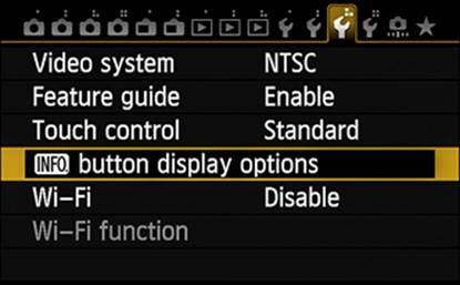
Figure 15-33. Selecting the INFO Button Display Options option
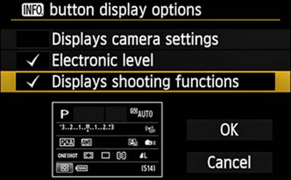
Figure 15-34. An example INFO Button Display Options setting
By default, all three screens are selected and there is a blank screen that is always part of the display set. Once the selections are made, pressing the INFO button cycles through whatever screens are selected, one screen for each press of the INFO button.
Wi-Fi
Wi-Fi is available only when enabled. Once you have set up the Wi-Fi Function configuration, you will likely only need to come to this Set Up3 menu option to enable or disable the wireless connection.
Wi-Fi Function
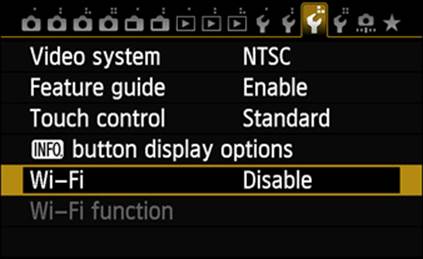
Figure 15-35. Selecting the Wi-Fi option
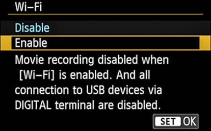
Figure 15-36. Choosing a Wi-Fi setting
There are several variables to consider when setting up the Wi-Fi function, each of which requires specific data depending on the LAN Setup Method you choose, the type of wireless security you’ve implemented, etc. Once you’ve configured your Wi-Fi connection, you should never need to do it again.
You must assign a nickname for the camera; this is any arbitrary name, up to 16 characters in length, but it should be a meaningful name, especially if you have or will be adding other Wi‑Fi capable cameras to the network. If there has not been a nickname previously assigned to the camera, as shown in Figure 15-38, you will be invited to generate one as soon as you select the Wi-Fi Function option on the Set Up3 tab. If a nickname already exists, you can change that name later in this process.
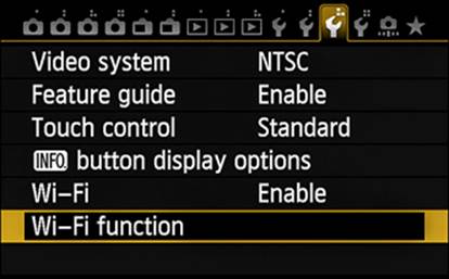
Figure 15-37. Selecting the Wi-Fi Function option
keyboard. On the EOS 70D, there is a special key in the lower-right corner of the keyboard that allows selection of one of four keyboards. The icons on that special key represent a keyboard of upper-case alphabetic characters, a keyboard of lower-case alphabetic characters, a keyboard of the ten single-digit numeric characters plus many of the special characters commonly found on a computer keyboard, and a keyboard with the ten single-digit numeric characters plus most of the remaining computer-keyboard special characters.
Touch the OK icon, or select the OK setting and press SET, and in the next window there will be an empty blue-bordered text box that you will use to enter or edit text. Press the Quick Control button to move the blue border down to the “keyboard” (Figure 15-39). All the uppercase and lowercase letters are available, as well as all ten single-digit numerals and a good selection of special characters. The space character is represented by the special character in the lower-left corner of the of which
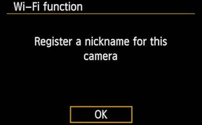
Figure 15-38. Invitation to provide a nickname
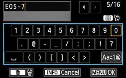
Figure 15-39. The editing window
There is a small, gold-bordered rectangle that identifies the currently selected character (in Figure 15-39, the digit 0). You can use either the Main Dial or the Quick Control Dial to slowly navigate the keyboard, or use the Multi-controller, but the fastest means is to simply touch the desired keys. The Multi-controller allows you to move vertically and horizontally on the keyboard, making a slow job not quite as slow. If you are using the Quick Control Dial or the Multi-controller, once you have selected a character, press the SET button to have the character displayed in the text box. The upper-right corner of this screen shows a number representing the number of characters entered thus far and another number showing the maximum number of characters that can be entered in this field (in Figure 15-39, those numbers appear as 5/16). After you have finished creating the string of characters, press the Quick Control button again, returning the focus to the text box.
If you see that there is an error, you can use the Multi-controller or either of the two dials to place the gold vertical bar to the right of a character you want to delete. Press the Erase button (the garbage can icon). Using the touch feature, this procedure becomes very simple: repeatedly touch the left arrow to the right of the text box until the gold-colored cursor is to the right of the character to be deleted, and press the Erase button. Using either technique, you now must press the Quick Control button to reselect the keyboard, and then touch or navigate to the desired replacement character(s).
There is a pair of icons to the right of the text box. The leftmost icon represents the Quick Control button and the icon to its right indicates switching between the text box and the keyboard box. Be very careful about pressing the INFO button. Based on other menus, it’s easy to presume that pressing the INFO button will display related help panels; in this menu, pressing the INFO button will close the screen, ignoring any changes you have just made. To have your changes recorded in the camera’s memory, touch the OK icon, or press the MENU button (another uncommon use of a button).

Figure 15-40. Selecting a Wi-Fi Function target
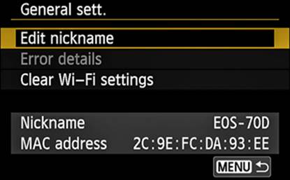
Figure 15-41. Choosing a General Sett. setting
Many of the supported wireless applications use devices that will require their own communication configurations. Only the Remote Control (EOS Utility) connection, identified by the computer icon, is covered in this section; however, the other setup procedures are similar. The environment will consist of a computer and the camera, connected via a wireless router, in a LAN (local area network).
On the screen shown in Figure 15-40, you have the opportunity to select the wireless application you want to configure. If you have already created a nickname for the camera but wish to change it, press the INFO button (a hint is in the lower-left corner of Figure 15-40) to open the General Sett. panel (shown in Figure 15-41), which offers the Edit Nickname function. You’ll notice that the current nickname is also shown, along with something called the MAC Address. Don’t panic—this MAC has nothing to do with Apple’s Mac. MAC is an acronym for Media Access Control, but the media in this case are all the physical devices involved in the LAN communication. Each has a unique MAC address, usually assigned by the manufacturer.
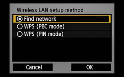
Figure 15-42. Choosing a Wireless LAN Setup Method
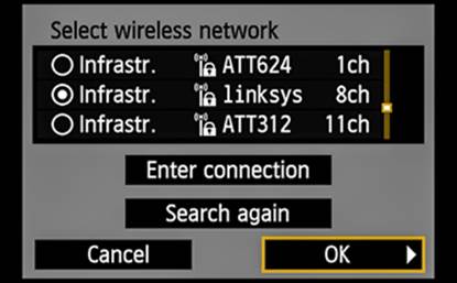
Figure 15-43. Selecting a wireless network
Progressing through the configuration screens, you will encounter the one shown in Figure 15-42. If you know that you have a router that supports WPS (Wi-Fi Protected Setup), you can then select the WPS feature (PBC [Push Button Configuration] mode) or the WPS feature (PIN [Personal Identification Number] mode) provided by that router. The remainder of the setup is pretty straightforward in that case. However, if WPS is not available, select the Find Network setting, touch the OK icon, or select OK and press SET. Assuming the camera can locate an operational wireless router, you should see a screen similar to the one shown in Figure 15-43. Available routers are listed with their SSIDs (Service Set Identification), as shown in the column starting with ATT264 in Figure 15-43. Touch the SSID that indicates your router and touch the OK icon, or select it and select OK and press SET.
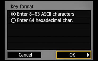
Figure 15-44. Selecting the Wi-Fi Key Format
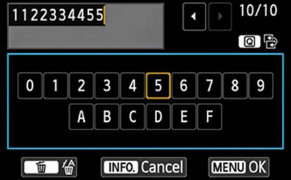
Figure 15-45. Generating an ASCII password
As shown in Figure 15-44, you now must select the key format (type of password) already in use on your wireless network, then use Figure 15-45 as a guide to entering that password. The instructions provided earlier for Figure 15-39 apply here as well.
All Internet addresses are actually strings of numbers—for example, when you search: consumer.usa.canon.com, the Internet actually searches for 146.184.152.44). These strange sets of numbers are known as IP (Internet Protocol) addresses, and are used to locate specific sources on the Internet. From Figure 15-46, try Auto Setting first. If that works, you will see a screen like that in Figure 15-47, which encourages you to start the pairing process (which we will cover shortly). Otherwise, you will need to use the Manual Setting option, which will open a screen allowing you to enter the IP address.
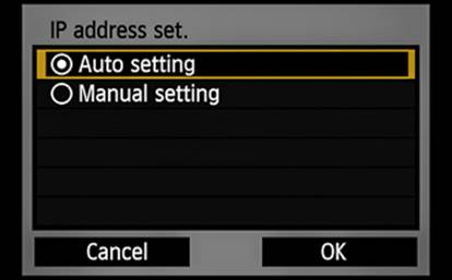
Figure 15-46. Selecting an IP Address Set. option
It’s now time to establish the connection between the camera and the computer. On the computer, start the WFT Pairing software (previously installed from the EOS Utility package on the software CD).
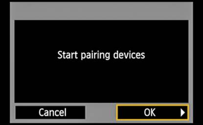
Figure 15-47. The invitation to start the pairing process
Now, as shown in Figure 15-49, touch the OK icon, or select OK and press SET.
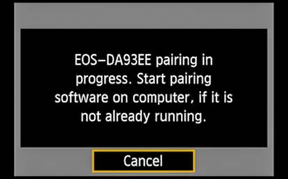
Figure 15-48. Pairing progress message
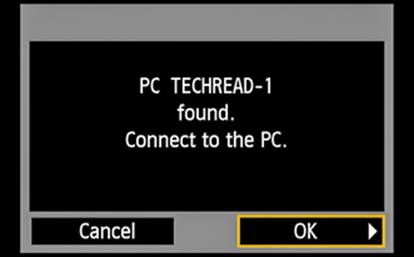
Figure 15-49. Results from the WFT Pairing Software
The icon shown in Figure 15-50 will appear in the system tray portion of the Windows taskbar.
![]()
Figure 15-50. The WFT Pairing icon on the Windows taskbar
Set Up4

Figure 15-51. The Set Up4 tab
Sensor Cleaning
During the process of changing lenses, there is always the opportunity for dust, lint, or other airborne particulates to enter the body of the camera. If they settle on the sensor, they interfere with the ability of the pixels at that location to accurately determine the characteristics of the light, generally resulting in an odd-shaped gray blur on the final image, commonly called a dust spot. To help manage that situation, Canon provides the Sensor Cleaning option in the Set Up4 menu.
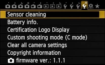
Figure 15-52. Selecting the Sensor Cleaning option
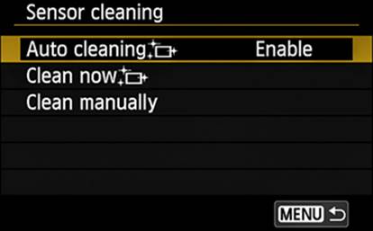
Figure 15-53. Choosing a Sensor Cleaning setting
By default, the camera is set to automatically run sensor cleaning every time the power switch is turned ON or OFF (you should see an image on the LCD Monitor like that in Figure 15-54), but the Auto Cleaning setting can be set to Disable, if you wish.
The Clean Now option begins the cleaning process on demand. Touch the option and touch the OK icon; or, select the option, press SET, select OK, and press SET. You may hear some internal clicking, but no pictures are being recorded. Again, the graphic shown in Figure 15-54 is displayed on the LCD Monitor while the sensor cleaning is in progress.

Figure 15-54. The LCD Monitor display during sensor cleaning
Some contaminating particles tend to be a bit sticky and may not shake off the sensor. Running Clean Now more than once is generally not going to improve things. If the particles don’t shake off the first time, they’re probably not going to be removed with this technique. It’s now time to get serious. Manually cleaning the sensor is not for the faint of heart. Most professionals simply won’t take the risk of potential damage while attempting to clean the sensor, and will send the camera to a Canon service center for cleaning. If you’re desperate, ensure that you have a fully charged battery or are using the ACK-E6 AC adapter. Loss of power during this procedure can result in extensive (and very expensive) damage to the shutter, the reflex mirror, or the sensor.
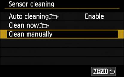
Figure 15-55. Choosing the Clean Manually setting
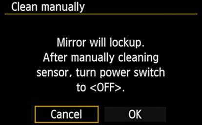
Figure 15-56. The Clean Manually confirmation screen
With a proven power source, remove the lens from the camera body, touch the Clean Manually option and touch the OK icon on the next screen; or, select the Clean Manually option, choose the OK button, and press SET. Wait for the reflex mirror to lift and the shutter to open. Insert the tip of a commercially available blower designed for working with cameras into the lens mount flange, and squeeze the blower’s bulb strongly. That’s about as well as you can do on your own. Remove the blower tip from the camera, and turn the camera off. The shutter will then close and the reflex mirror will reseat itself. You can now remount the lens. Never use canned air or other cleaning gases on a sensor, and never use your blower bulb for anything—especially transferring liquids—other than sensor cleaning.
If there is intractable dust on the sensor, you may want to consider capturing Dust Delete Data for processing later. This process essentially subtracts dust-spot images captured in the Dust Delete Data from your images, effectively eliminating the dust spots. The software that comes with the camera is capable of performing that step.
Battery Info
In the field, we’re totally dependent on the camera battery to keep us operational. Therefore, monitoring battery condition is critical to long-term success. It’s easy enough to turn the camera on and look down at the battery icon on the LCD Panel to ensure that you have a good charge on the battery, but remember that charge capacity varies over the life of a battery.
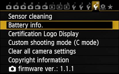
Figure 15-57. Selecting the Battery Info. option
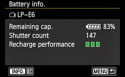
Figure 15-58. The status screen for the currently installed battery
When you select the Battery Info. option in the Set Up4 menu and then press SET, you will see something like the screen in Figure 15-58. An identifier for the battery, which should be LP-E6 unless you are using the ACK-E6 AC adapter (in which case you will see DR-E6, as shown inFigure 15-60), will be at the top. Note that if you are using the AC adapter or the BG-E14 battery grip with AA or LR6 batteries, there are no data for shutter count or recharge performance. The data on the screen shown in Figure 15-58 relate only to the battery currently in the camera.
The Remaining Capacity data shows, within 1%, the available battery charge. The Shutter Count field provides the number of still-photo images captured since this battery was last recharged (at which point the count is set to zero). Possibly the most significant data is that associated with Recharge Performance. Three green bars, as shown here, indicate a healthy battery capable of accepting a full charge. Two green bars indicate that the battery’s ability to accept a full charge has been diminished, and a single red bar advises you that it’s probably time to buy a new battery.
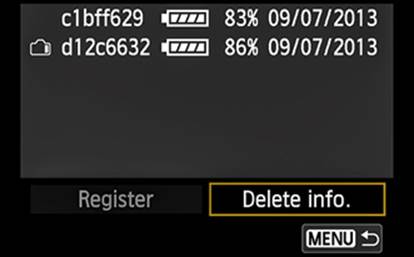
Figure 15-59. The INFO status screen for all registered batteries
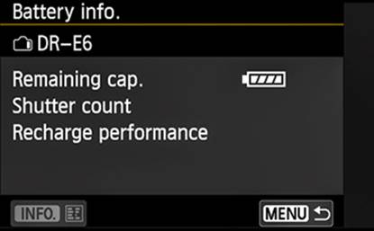
Figure 15-60. The Battery Info. screen content when the AC adapter is installed
If you press the INFO button while on this screen, you will see something like Figure 15-59. If the data display for a battery is in gray, you know that the data is derived directly from the current battery, and that this battery has never been registered with this camera. A new piece of datum, the serial number of the battery, is now shown on the far left of the line. This serial number is not displayed anywhere on the battery’s external surface. (If you bought a new battery, dropped it into the camera, accessed the Battery Information option, and looked at this data, but there was no serial number or there were other problems in getting to this display, you almost certainly have a non-Canon battery.) Once you register this number in the camera, it will be displayed in typical bright white. If you have additional batteries that you use exclusively with this camera, you may want to register them as well. You can register up to six batteries. That can help you choose which battery to use after you’ve drained the current one. Though the battery’s serial number is not displayed on the outside of the battery, Canon does encourage you to copy it onto a small, gummed label to be applied to the non-contact end of the battery. The camera icon at the left margin of Figure 15-59 serves to identify the battery currently installed in the camera.
Certification Logo Display
This is another feature of questionable value to me, especially while on my hands and knees trying to capture a Calochortus obispoensis. There are certification logos on the camera body, the lens, the packaging, and in the Instruction Manual. The Certification Logo Display menu shows two such logos, but neither the menu nor the Instruction Manual offers information about what these particular logos represent, nor why I should be aware of them.
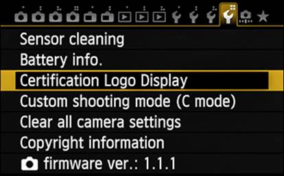
Figure 15-61. Selecting the Certification Logo Display option
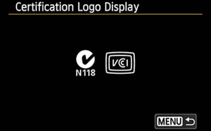
Figure 15-62. Contents of the certification logo display
Custom Shooting Mode (C Mode)
Very few of us are in a position to have several camera bodies, each already set up for a specific task. We have to accept the fact that we may need several minutes to reset the camera for a distinct function. There is a better way! If you’re preparing for a day on your hands and knees, getting up close and personal with small bits of nature, you may spend some time in the comfort of your room getting all the settings established ahead of time. Once that is done, open the Set Up4 menu and click the Custom Shooting Mode (C Mode) option.
Spend a few minutes setting the buttons and menus to the values you will need for this customized camera setup. Select the Register Settings option. Touch the OK icon, or select OK and press the SET Button to save this collection of configuration data. Now, by simply rotating the Mode Dial to C, you’ve just set the camera to that configuration. Maybe you set up C for action shooting, using features such as Shutter-Priority AE, High-Speed Continuous drive mode, and AF optimized for tracking. In each of those instances, all you need to do to access the associated collection of configuration data is simply rotate the Mode Dial to the C Mode.
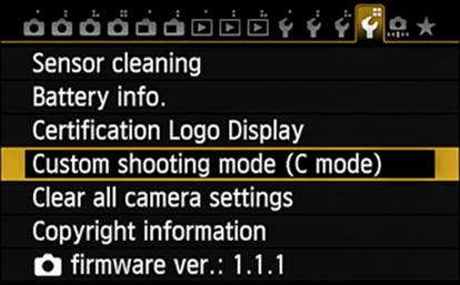
Figure 15-63. Selecting the Custom Shooting Mode (C Mode) option
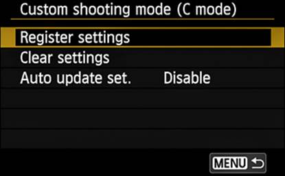
Figure 15-64. Choosing a Custom Shooting Mode (C Mode) setting
You may find that the configuration you’ve saved is wrong or that you simply don’t use it enough to justify maintaining it. In that case, select the Clear Settings option, press SET, select OK, and press SET.
With some use, you may find that you need to alter some of the settings that were captured with the Custom Shooting Mode. After you’ve made those changes to your camera settings, you can enable the Auto Update Set. option and the camera will modify the registered data to incorporate those changes. The biggest shortcoming of this feature is that there is no opportunity for you to provide any kind of identifier to remind you of the intended use for a particular Custom Shooting Mode.
So, functionally, you now have a second camera defined by the C Custom Shooting Mode, plus the camera that responds to Mode Dial positions other than C. With the EOS 70D costing $1,200 per body, you just saved $1,200. Not bad for an afternoon’s efforts. Not to mention not having to drag another pound-and-a-half of camera body around on your venture.
Clear All Camera Settings
This is a strange juxtaposition of menu options: once you’ve used the Custom Shooting Mode (C Mode) option in this menu, the Clear All Camera Settings option will specifically not clear any settings established in the Custom Shooting Mode (C Mode) option. Other than that, the Clear All Camera Settings option will reset most shooting settings and menu settings to their factory default values.
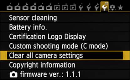
Figure 15-65. Selecting the Clear All Camera Settings option
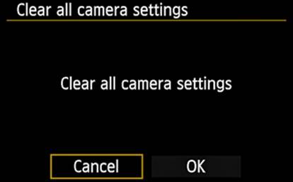
Figure 15-66. The Clear All Camera Settings confirmation screen
You may find it valuable to peek at the lists on pages 61 through 63 of the Instruction Manual to see just what these default values are. Note that some camera settings are not cleared, including Date/Time/Zone, Language, and My Menu settings.
Copyright Information
This option allows you to enter an author’s name, and provides an additional field called Copyright Details. Each of these fields is capable of accepting up to 63 characters. Whatever you provide in the Copyright Details field will be recorded with each image as IPTC metadata.
In the Set Up4 menu, touch Copyright Information, or select Copyright Information and then press SET. Use the touch feature, or use the Quick Control Dial or the Multi-controller to select the desired setting and then press SET. If you choose either of the Enter ... options, you will initially see an empty blue-bordered text box that you can use to enter or edit text, as shown in Figure 15-69.
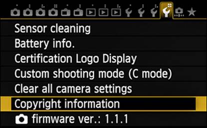
Figure 15-67. Selecting the Copyright Information option
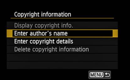
Figure 15-68. Choosing a Copyright Information setting
Press the Quick Control button to move the blue border down to the “keyboard.” Notice that all the uppercase and lowercase letters are available, as well as all ten single-digit numerals and a good selection of special characters. The space character is in the lower-left corner of the box. There is a small, gold-bordered rectangle that identifies the currently selected character (in Figure 15-70, the space character).
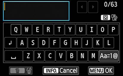
Figure 15-69. The initial text creation screen
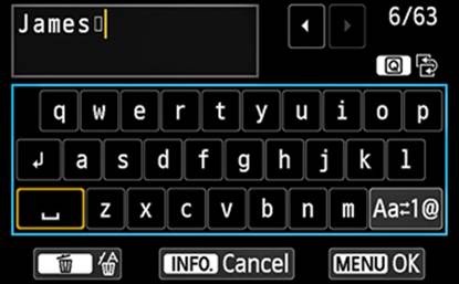
Figure 15-70. Selecting text for the author’s name
You can use the Main Dial, the Quick Control Dial, or the Multi-controller to navigate the keyboard; once you have selected a character, press the SET button to have the character displayed in the text box. Or, you can simply touch the desired character on the keyboard and have that character immediately displayed in the text box. The upper-right corner of this screen shows a number representing the number of characters entered thus far and another number showing the maximum number of characters that can be entered in this field (in Figure 15-70, those numbers appear as 6/63). After you have finished creating the string of characters, press the Quick Control button again, returning the focus to the text box.
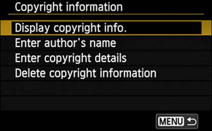
Figure 15-71. Choosing the Display Copyright Info. setting
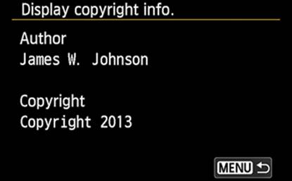
Figure 15-72. A display of the recorded copyright information
If you see that there is an error, you can use the touch feature and the arrows, the Multi-controller, or either of the two dials to place the gold vertical bar to the right of a character you want to delete. Touch the Erase icon or press the Erase button (the garbage can icon) to delete the character.
Like choosing a nickname for your camera during Wi-Fi setup, there is a pair of icons to the right of the text box. The first of these two icons represents the Quick Control button and the other indicates switching between the text box and the keyboard box. This is another instance when pressing the INFO button will not display related help panels; instead, it will close the screen, ignoring any changes you have just made. To have your changes recorded in the camera’s memory, press the MENU button (another uncommon use of a button).
If you find that you are frequently changing the Copyright Details field, you may want to explore using the EOS Utility software. With that software, you can check the current setting as well as create a new setting—and you get to use a real keyboard!
Camera Firmware Ver.
Firmware is the computer term used to describe the low-level programs in the camera that control its every function and provide the user interface we all depend on to utilize the vast array of functions and controls. Firmware updates can correct functions that are not working in unusual situations, and add valuable functions to the camera. This firmware update is another process that must be carefully followed. It requires a good power source—a fully charged battery or the ACK-E6 AC adapter. It can be difficult to recover from loss of power in the middle of this process.
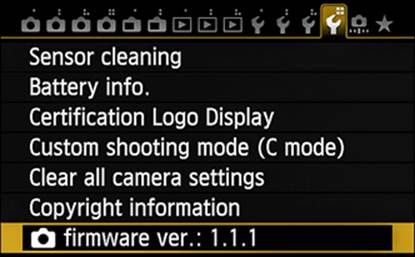
Figure 15-73. Selecting the Firmware Version option

Figure 15-74. Invitation to start the firmware update
As you can see in Figure 15-74, the camera can also present data on the firmware version for some lenses as well. (Providing firmware in a lens is a relatively recent innovation, so most of the lenses available today will not report a firmware version number.) If the lens on the camera does not provide firmware support, selecting the Camera Firmware Ver. option in Figure 15-73 will immediately search the memory card for the updated software. If no updates are found, you will see the message in Figure 15-75 alerting you that the camera needs a memory card with the new firmware in order to provide an update. You should periodically check the Drivers and Software tab on the lens’s or camera’s page at the Canon website to see if the firmware version identified in this option is a smaller number than the version available from Canon.
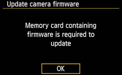
Figure 15-75. Result when the memory card in the camera does not contain a firmware update
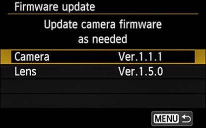
Figure 15-76. Invitation to start the firmware update
In Figure 15-73, Firmware Version 1.1.1 is shown as installed on my camera. The Canon website shows that no firmware update is currently (year-end 2013) available, so I will describe the process for the EOS 6D camera.
On the web page shown in Figure 15-77 (the URL for the EOS 70D is either http://www.usa.canon.com/cusa/professional/products/professional_cameras/digital_slr_cameras/eos_70d#DriversAndSoftware orhttp://www.usa.canon.com/cusa/consumer/products/cameras/slr_cameras/eos_70d#DriversAndSoftware), click on the bold text reading “EOS 6D Firmware Version n.n.nn (operating system)” to open the web page shown in Figure 15-78. If you want to better understand the changes and improvements introduced in this update version, click the bold text line that reads “Driver/Software Details” as seen in Figure 15-78. In either case, at the bottom of this page is a button called “I Agree—Begin Download.”
Of course, if the current firmware version offers no advantage to you, then you may choose to wait until the next version is available. Be aware that the versions are not in tight numerical order (version 1.0.9 was followed by version 1.1.2), though the newer version always has a higher number than its predecessor.
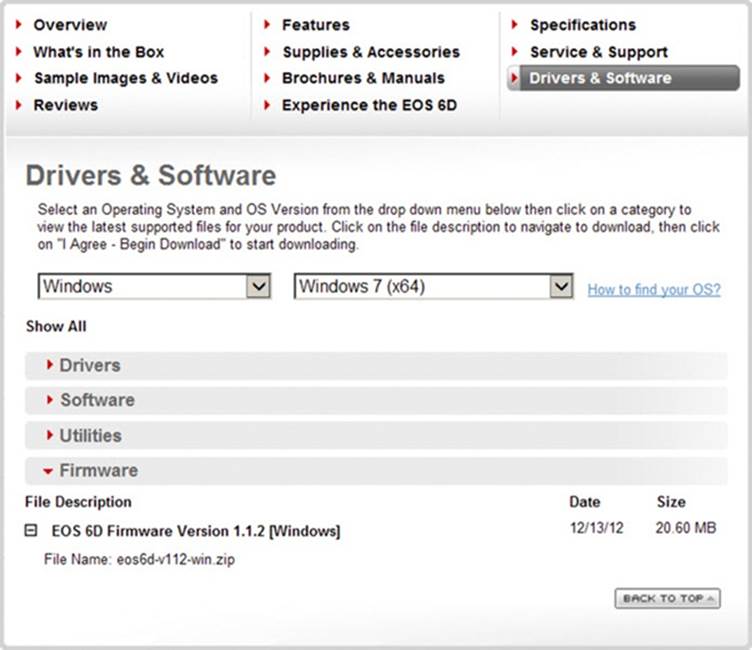
Figure 15-77. Checking the current firmware version available for the EOS 6D from the Canon website
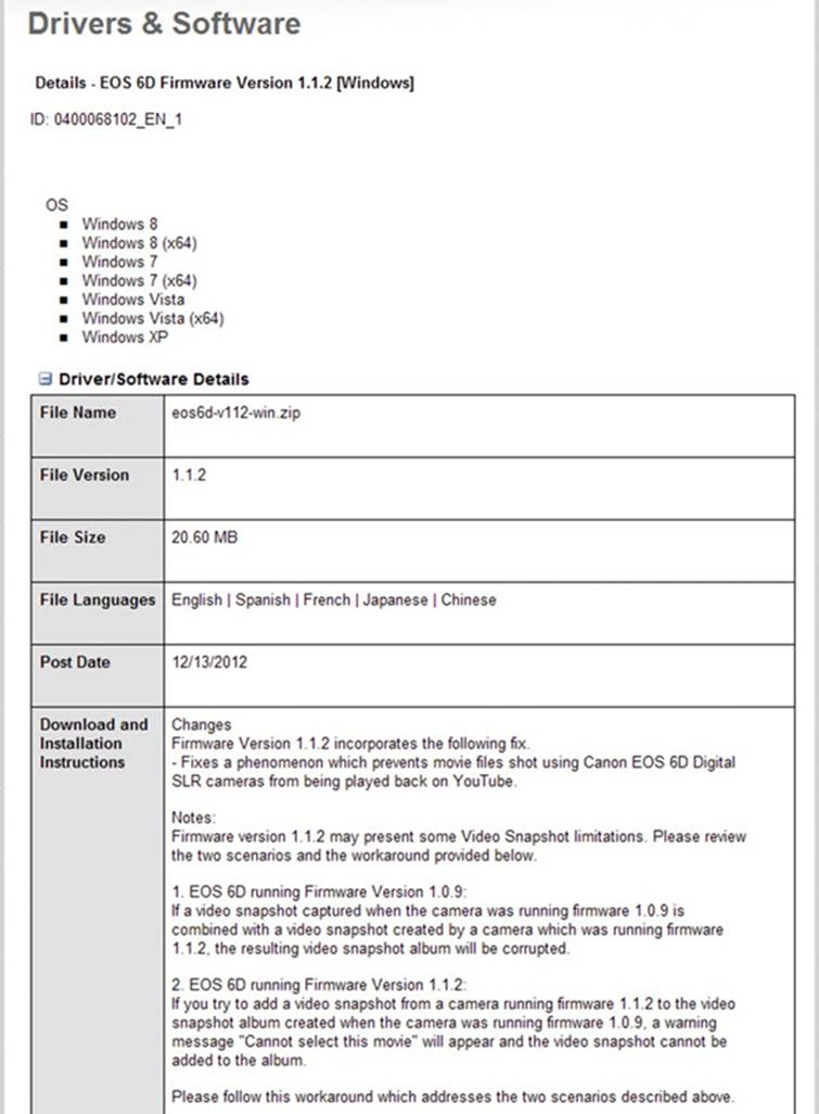
Figure 15-78. The changes introduced for the EOS 6D by firmware update version 1.1.2
All materials on the site are licensed Creative Commons Attribution-Sharealike 3.0 Unported CC BY-SA 3.0 & GNU Free Documentation License (GFDL)
If you are the copyright holder of any material contained on our site and intend to remove it, please contact our site administrator for approval.
© 2016-2026 All site design rights belong to S.Y.A.