Canon EOS 70D: The Guide to Understanding and Using Your Camera (2014)
Chapter 2. Parts and Purposes

Camera Body Reference
From the Back
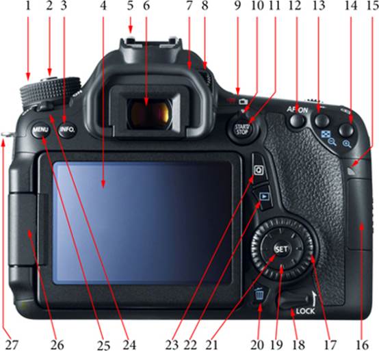
Figure 2-1. Key parts of the camera’s back
1 Mode Dial
2 Mode Dial Lock Release button
3 INFO button
4 LCD Monitor
5 Hot shoe
6 Viewfinder eyepiece
7 Eyecup
8 Dioptric adjustment knob
9 Movie (red) and Live View (white) selection icons
10 Live View/Movie shooting switch
11 Live View/Movie Start/Stop button
12 AF-ON (Autofocus Start) button
13 AE Lock/FE Lock button
14 AF Point Selection button
15 Access lamp
16 SD memory card access panel
17 Quick Control Dial
18 Multi-function Lock switch
19 Multi-controller
20 Erase button
21 SET button
22 Playback button
23 Quick Control button
24 Power switch
25 MENU button
26 Hinge for LCD Monitor
27 Strap mount
From the Top
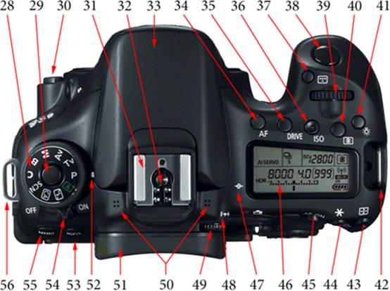
Figure 2-2. Key parts of the camera’s top
28 Mode Dial
29 Mode Dial Lock Release button
30 Lens Release button
31 Hot shoe
32 Hot shoe contacts
33 Built-in flash
34 AF (Autofocus Operation Selection) button
35 DRIVE (Drive Mode Selection) button
36 ISO (ISO Speed Setting) button
37 AF Area Selection Mode button
38 Shutter button
39 Main Dial
40 Metering Mode Selection button
41 LCD Panel Illumination button
42 Strap mount
43 AF Point Selection button
44 AE Lock/FE Lock button
45 AF-ON (Autofocus Start) button
46 LCD Panel
47 Focal plane mark
48 Dioptric adjustment index
49 Dioptric adjustment knob
50 Stereo microphones
51 Eyecup
52 Mode Dial index mark
53 INFO button
54 Power switch
55 MENU button
56 Strap mount
From the Front
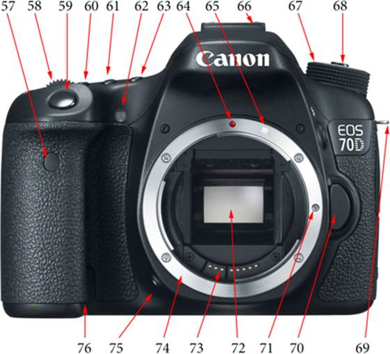
Figure 2-3. Key parts of the camera’s front
57 Remote control sensor
58 Main Dial
59 Shutter button
60 ISO (ISO Speed Setting) button
61 DRIVE (Drive Mode Selection) button
62 Self-timer lamp
63 AF (Autofocus Operation Selection) button
64 EF lens-mount index
65 EF-S lens-mount index
66 Hot shoe
67 Mode Dial
68 Mode Dial Lock Release button
69 Strap mount
70 Lens Release button
71 Lens Lock pin
72 Sensor (with mirror flipped in up position)
73 Lens contacts
74 Lens mount
75 Depth-of-Field Preview button
76 DC coupler cord hole
From the Bottom
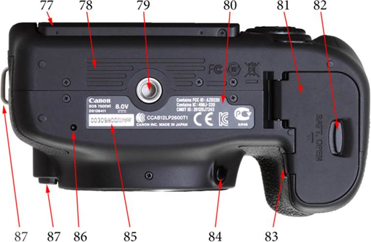
Figure 2-4. Key parts of the camera’s base
77 LCD Monitor
78 Friction mat
79 Tripod socket
80 Data plate
81 Battery compartment cover
82 Battery compartment cover release lever
83 DC coupler cord hole
84 Depth-of-Field Preview button
85 Serial number
86 Battery grip locating pin socket
87 Strap mount
From the Left Side (Closed)
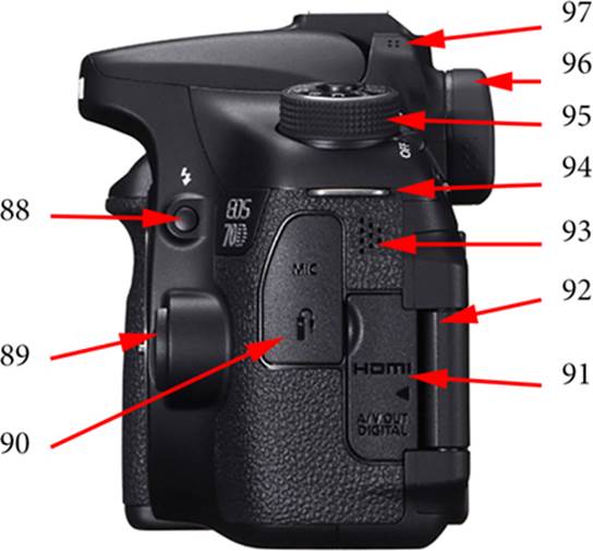
Figure 2-5. Key parts of the camera’s left side, closed
88 Manual release for built-in flash
89 Lens Release button
90 Left terminal access panel
91 Right terminal access panel
92 LCD Monitor hinge
93 Speaker
94 Strap mount
95 Mode Dial
96 Eyecup
97 Left stereo microphone
From the Left Side (Open)
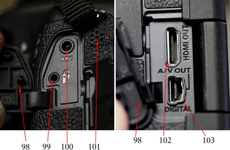
Figures 2-6a and 2-6b. Key parts of the camera’s left side, open
98 Flexible port covers
99 Pin-type remote control socket
100 MIC (external microphone IN) socket
101 Monaural speaker
102 HDMI mini OUT terminal
103 A/V OUT/DIGITAL terminal
From the Right Side (Closed)
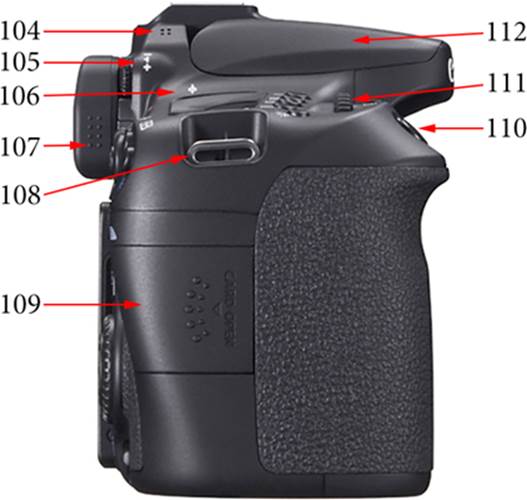
Figure 2-7. Key parts of the camera’s right side, closed
104 Right stereo microphone
105 Dioptric adjustment index
106 Focal plane mark
107 Eyecup
108 Strap mount
109 Card slot cover
110 Shutter button
111 Main Dial
112 Built-in flash
From the Right Side (Open)
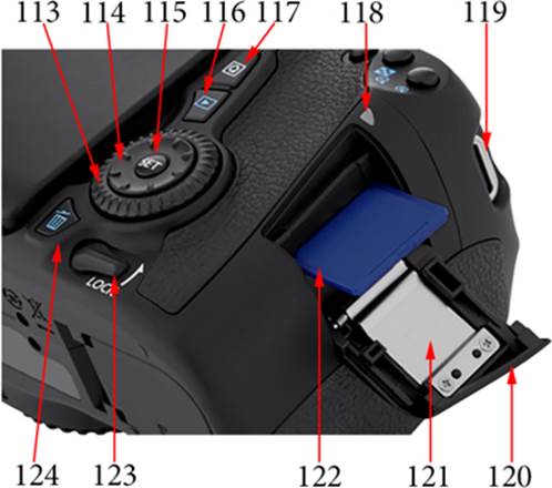
Figure 2-8a. Key parts of the camera’s right side, open
113 Quick Control Dial
114 Multi-controller
115 SET button
116 Playback button
117 Quick Control button
118 Access lamp
119 Strap mount
120 Card slot cover
121 Card insertion outline (see Figure 2-8b)
122 SD memory card
123 Multi-function Lock switch
124 Erase button
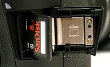
Figure 2-8b. The memory card insertion outline
Functional Descriptions
From the Back (See Figure 2-1)
1. Mode Dial. The purpose of this dial is to instruct the camera regarding your style of shooting. That style can change as quickly as rotating the dial to a different option. If you’re quite familiar with older Canon cameras, be aware that this camera—like most of the newer Canon DSLRs—has a Mode Dial Lock Release button (see #2) in the center of the Mode Dial that must be depressed for the Mode Dial to rotate.
2. Mode Dial Lock Release button. Starting with the Canon EOS 60D, most Canon DSLRs have included this lock release button (Canon can reportedly convert Canon EOS 5D Mark II and Canon EOS 7D cameras, giving them a Mode Dial Lock and a Mode Dial Lock Release button). Earlier cameras were subject to unintended Mode Dial rotation caused by the camera rubbing across body parts while being carried by the neck strap. On newer cameras, you must press and hold the lock release button while rotating the Mode Dial. It’s one more nuisance, but it reduces embarrassment caused by the Mode Dial having been accidentally rotated to M (Manual Exposure) when you were sure you had set it to Av (Aperture-Priority automatic exposure).
3. INFO button. This is a rather versatile button. From its factory-default position: when you press the INFO button while setting up for a shot, a quick summary of the more significant selected camera settings are displayed. Pressing it a second time shows a two-dimensional electronic level. The screen for the electronic level will show an edge-to-edge red line when the camera is not level left-to-right; that line becomes green as you level the camera. A third press of the INFO button displays shooting data, and if you press one of the five function-control buttons in front of the LCD Panel, you can alter the setting of this display. (In fact, you can access any of the values in the display by pressing the Q button [see #23].)
As you navigate menus, you will see an icon representing the INFO button at the bottom of the display. This is to advise you that the camera can provide explanatory text about the camera’s features when you press the INFO button. Some of this text requires more space than the screen supports, and in those instances, you’ll need to use the Quick Control Dial to scroll through the remaining text. In a few instances, the on-screen INFO label indicates that the button will do something other than give you access to help. For example, in the Picture Style menu, the INFO button is used to access the Detail Set for a specific Picture Style. Keep a sharp eye out for these exceptions.
If the INFO button is pressed during playback or immediately after an exposure (while the image is still being displayed on the LCD Monitor), you’ll see some exposure data overlaid on the image. Press the INFO button again and you’ll get basic setting information along with a smaller image and a brightness histogram. When you press the button a third time, the display changes to remove some of the exposure data and add RGB histograms. If you used an optional Canon GPS receiver while that image was being captured, that GPS data is shown on this screen instead of the normal subset of exposure data. You can select one of these three information-display options as the desired manner in which to view images either immediately after capture or during playback. Your selection will remain active through power-off and power-on.
4. LCD Monitor. This three-inch (diagonal) LCD is about as large as it can be without increasing the size of the camera. With over a million dots for resolution, it gives you a clear, sharp image with good contrast and color. In normal shooting, you can use the LCD Monitor to briefly view the result of an image capture and look at the histogram to confirm there was no loss of highlights. You can also use it to check or change menu settings, and to play back previously captured images. During movie and Live View shooting, the LCD Monitor replaces the optical viewfinder, allowing you to see in real time what the image on the sensor looks like.
The EOS 70D has added some very nice enhancements to the LCD Monitor. The first is that the panel is articulated, and is able to swivel out from the camera body as well as rotate when opened away from the camera body. This should be a real boon for those into taking selfies (self-portraits), but has a very practical advantage for shooting over a crowd, close to the ground, or anytime that the optical viewfinder is of no value. The second enhancement is the touch-sensitive feature. Many operations that used to require dial spinning and button pushing can now be performed simply by opening the Quick Control panel and touching the desired feature on the LCD Monitor. This touch-sensitivity is capacitive, which means that the screen is responsive to the change in voltage caused by your body-part (typically the ball of your finger) as you lightly touch the screen. The screen is not sensitive to pressure.
5. Hot shoe. Every camera worth having (in my opinion) has a shoe on top. Some shoes simply hold an accessory in place and provide no electrical connection between the camera and the accessory. However, a hot shoe does provide an electrical connection (see #32). In most instances, the hot shoe is used to attach an electronic flash unit or the controller for remote electronic flash units. However, more and more devices are being built to utilize the hot shoe for both anchoring a device (e.g., some remote-control units) and for communication with the camera (such as some GPS units).
6. Viewfinder eyepiece. Except during Live View and movie shooting, this is where you will observe your subject, compose your photograph, and confirm focus and exposure settings. Be sure to use the dioptric adjustment knob (see #8) to get the clearest, sharpest image.
7. Eyecup. The purpose of an eyecup is to reduce the amount of light that can sneak into the viewfinder, possibly causing erroneous exposure meter readings. The standard Canon eyecup serves most users well. However, if you will be using the camera in bright sunshine or a brightly lit interior, you may decide you need to block most of the brightness that creeps in between the eyecup and your face. A number of manufacturers offer eyecups for that purpose.
Personally, I like the Hoodman HoodEYE eyecup. For the Canon EOS 70D, Hoodman provides an eyecup for use without glasses as well as a version for use with glasses; however, when this eyecup is used with the EOS 70D, the LCD Monitor must remain closed—a real disadvantage. Any replacement eyecup will extend a bit farther away from the back of the camera, so consider how you stow and carry your camera to ensure that this extra protrusion does not become a problem.
Of course, when the camera is mounted on a tripod and you are triggering the shutter by remote control, or you’re using the self-timer so that you can get into the picture, your face is not up against the camera body, so there is the potential for significant light leakage through the viewfinder. To address that problem, Canon threads a soft silicone rubber eyepiece cover onto the Wide Strap EW-EOS70D camera strap. The eyepiece does not need to be removed from the camera strap for use. To cover your viewfinder with it, simply squeeze the two sides of the eyecup and pull upward to remove it, then slide the eyepiece cover over the eyecup mounting rails. The process is illustrated in the Instruction Manual, on page 183. Once you’ve seen the drawings, you should have no problems recalling how to do it. If you need to recompose for a subsequent photograph, simply raise the eyepiece cover. Remember: the purpose of the eyepiece cover is to prevent erroneous exposure meter readings. Therefore, ensure that the eyepiece cover is in place before you press the Shutter button halfway, which is when that meter reading is determined.
Since the mirror is raised during Live View shooting and movie shooting, light leakage is not a problem; therefore, there is no need for the eyepiece cover.
8. Dioptric adjustment knob. This little knob, hiding just behind the upper-right corner of the eyecup, allows a degree of optical compensation for each individual’s eyes, or at least the eye that is used to compose a picture. The trick is to simultaneously look through the viewfinder and rotate this knob through its range, slowly narrowing in on the clearest view. How to determine that clearest view is a discussion in itself. Some photographers say to set the camera up on a tripod and let it focus on a distant object, then use the knob to fine-tune the viewfinder. Others say to turn on the meters by pressing the Shutter button down halfway, and adjust the dioptric setting by observing the AF points or by using the exposure information at the bottom of the viewfinder. Distance to the subject has no bearing on this setting. In fact, you can eliminate a lot of distracting imagery by placing the lens cap on the lens and holding the Shutter button halfway down, then using the exposure data at the bottom of the viewfinder. If you find that your fingers are too big to manipulate this rather small knob, lift the eyecup, make the adjustment, then replace the eyecup. If the knob does not provide sufficient range, you may need to acquire one of Canon’s dioptric adjustment lenses. Have your optometrist help you determine which one you need.
9/10. Live View/Movie shooting switch and selection icons. In addition to what most of us consider normal DSLR photography, the Canon EOS 70D provides Live View shooting and movie shooting—we’ll touch on both subjects later in the book. This is a rotary switch that rotates through a very narrow angle, selecting one of two positions. The Movie shooting position is indicated by a red icon representing a movie camera, while the second position, indicated by a white icon of the back of a DSLR, is for Live View shooting.
It’s not intuitively obvious, but for normal photography, this switch should be in the Live View position. The camera does not actually enter Live View mode until the Start/Stop button is pressed.
11. Live View/Movie Start/Stop button. The Start/Stop button supports only Live View shooting or movie shooting, depending on the position of the Live View/Movie shooting switch. As its name indicates, pressing this button once initiates capture and pressing it again terminates capture.
12. AF-ON (Autofocus Start) button. Typically, you press the Shutter button halfway to start the autofocus system. However, there are situations when you don’t want to press the Shutter button, such as when you need to take a series of photos with uniform focus despite the fact that the composition may be significantly different in each photo. Pressing the AF-ON button will start the autofocus operation without the need for pressing the Shutter button. This technique works because when the AF-ON button is depressed, the Shutter button’s autofocus function is not operative. You can achieve focus once, and then take a number of shots while continuously holding down the AF-ON button. This works particularly well when you are shooting in Live View mode or Movie mode.
13. AE Lock/FE Lock button. The only identification you will find for this button is a white asterisk ( ![]() ) above it. You can press this button to lock the exposure that your camera set when you pressed the Shutter button halfway down. The AE Lock function allows you to lock in the correct exposure for your subject and recompose your photograph. The resulting image should show your final composition, with your subject properly exposed.
) above it. You can press this button to lock the exposure that your camera set when you pressed the Shutter button halfway down. The AE Lock function allows you to lock in the correct exposure for your subject and recompose your photograph. The resulting image should show your final composition, with your subject properly exposed.
When the EOS 70D is in playback mode, the AE Lock/FE Lock button is also used to display an index of recorded images or to reduce the displayed size of a selected image. (Notice that the Playback button is identified with a blue icon; any other button that uses a blue icon, such as this AE Lock/FE Lock button, performs the functions associated with that blue icon only when the Playback function is active.)
14. AF Point Selection button. This button is indicated by a white icon (![]() ). In terms of use, it may be second only to the Shutter button. The Canon EOS 70D has 19 AF points available for selection, giving you significant latitude in choosing the precise point for focusing, a real boon for macro work. On the EOS 70D, this button also has a blue icon representing a magnifying glass with a plus symbol, indicating that pressing this button while in playback mode will magnify the displayed image.
). In terms of use, it may be second only to the Shutter button. The Canon EOS 70D has 19 AF points available for selection, giving you significant latitude in choosing the precise point for focusing, a real boon for macro work. On the EOS 70D, this button also has a blue icon representing a magnifying glass with a plus symbol, indicating that pressing this button while in playback mode will magnify the displayed image.
15. Access lamp. This little lamps glows red whenever the camera is in the process of either reading or writing to a memory card. Its primary purpose is to alert you not to remove a memory card while the lamp is lit. Ignoring it can result in the loss of some, possibly all, images on the memory card. Certainly, writing a new image capture to the memory card will cause the lamp to light, but so do some not-so-obvious actions, such as applying effects to already recorded images; keep a close eye on that little lamp.
16. SD memory card access panel. To access the SD memory card, turn the camera off, use your finger to slide this panel toward the rear of the camera (about 1/8”), then release the panel. The panel will swing open, exposing the end of the SD memory card or the empty SD memory card slot.
17. Quick Control Dial. This is the navigation controller for many functions in the camera.
While in M mode (Manual exposure mode), without pressing any buttons, rotating the Quick Control Dial will adjust the aperture (rotating the Main Dial will adjust the shutter speed).
In working with menus, the Main Dial is used for moving horizontally through the sets of menus, and the Quick Control Dial is used for navigating vertically through the options for a given menu.
In playback mode, the Quick Control Dial is used to step through the images on the memory card, one at a time.
18. Multi-function Lock switch. The Canon EOS 70D is designed so that the Main Dial, the Quick Control Dial, and the Multi-controller can be used to make quick changes to many of the options that affect the composition and exposure of an image. Unfortunately, accidental movement of these controls, caused by the camera rubbing against you while being transported, can result in something quite different than what you anticipated. The specific purpose of the Multi-function Lock switch is to address this problem. Use the C.Fn III-2 menu to select which of the three—even all three if you wish—controls are to be deactivated when the switch is rotated counter-clockwise to its upper-most position. Operations that require pressing a button before the appropriate control can be used are not affected by the position of this switch.
19. Multi-controller. This is an eight-position ring of “keys” (Canon’s term) within the Quick Control Dial. There are a number of features that can be selected or managed by this controller. Common uses include selecting the AF point and navigating the Quick Control screen. The Multi-controller also allows you to move around on a magnified image in playback or on a magnified Live View image during composition. By pressing the rim of the controller, you can navigate in one of eight directions. Not all applications support the four diagonal positions, and some applications treat the controller in an unexpected manner. For example, when you press the Multi-controller sideways while navigating menus, it will navigate between menus, but when you press it up or down it will navigate within a menu. All eight keys are active when selecting or moving the AF point, correcting color balance, or moving the magnified frame in Live View or playback mode. Only the basic four keys (up/down, left/right) work within menus or on the Quick Control screen.
20. Erase button. This is another button I use rarely. I much prefer to make decisions about deleting images after viewing them on a large LCD monitor attached to my computer. However, if you are going to be showing images directly from the camera, such as in a slide show, or if your memory card is almost full and you need to make room for a few more shots, this is the button to use to eliminate obviously bad images. To delete a just-captured image currently displayed on the LCD Monitor, press the Erase button, rotate the Quick Control Dial (or press the right side of the Multi-controller) to select the Erase option, and then press the SET button. During playback of images on the memory card, the same procedure is used. If there are a number of images to be erased, you may find that using the Erase Images option on the Play1 menu is a bit faster and less tedious.
21. SET button. The SET button is in the center of the Quick Control Dial. Pressing this button is typically the means by which a selected image, option, etc. is chosen for further viewing, modification, or commitment.
22. Playback button. Pressing the Playback button displays the most recent recorded image. This display will be structured according to the last setting of the INFO button.
From the most recent image, you can move backward (chronologically) by rotating the Quick Control Dial counterclockwise, or forward by rotating it clockwise. (This scrolling can also be accomplished by pressing the left or right edges of the Multi-controller.) If you are viewing the most recent image and attempt to scroll forward, you will wrap around the list of images and the oldest image will be displayed.
23. Quick Control button. This is the button you use to display the Quick Control screen on the LCD Monitor. It is labeled with a Q on the button cap. You can use the Multi-controller to navigate the options on the LCD Monitor, press SET, and use either the Main Dial or the Quick Control Dial to alter the values associated with those options. All of these options can also be set using a variety of buttons and dials, but the Quick Control screen brings the most commonly adjusted settings together on one menu. And now, with the EOS 70D, you can use the touch feature to quickly navigate and make selections from the Quick Control screen.
24. Power switch. The power switch is a simple, two-position rotary switch, operated by a lever under the Mode Dial. Obviously, you must turn this switch to the ON position to use the camera. Just as important, the switch must be set to OFF whenever you are inserting or removing the battery or a memory card. Likewise, you should turn off the power switch whenever you are inserting or removing any cable at the terminal ports on the left side of the camera. Read the owner’s manual for any device you plan to attach to the hot shoe; some devices must be powered off before being attached, and many require that the camera be powered off, as well.
25. MENU button. Pressing the MENU button gives you access to all the camera’s customization menus, whether they are for fine-tuning captured images, shooting, setting up the camera, playing back images, or even personalization of the settings.
26. Hinge for the LCD Monitor. This is the hinge used for swinging the LCD Monitor open, from right to left, through a 175-degree arc. In the middle of this hinge is a vertical pivot that allows the LCD Monitor to rotate about 270 degrees in that second plane. I have used a similar fully articulated LCD Monitor on my EOS 60D for a couple of years with no problems, but please recognize that this is a fragile part of the camera.
27. Strap mount. Both strap mounts, used as a pair, are designed to carry the weight of the camera plus a lens. They cannot be removed, but seldom seem to be in the way. When attaching the Canon strap that comes with the camera, be sure to study the diagram on page 27 of the Instruction Manual. Use of any other technique may result in the strap slowly slipping until the camera falls, which is rarely advantageous.
From the Top (See Figure 2-2)
28. Mode Dial. See #1.
29. Mode Dial Lock Release button. See #2.
30. Lens Release button. This button is automatically engaged when a lens is mounted on the camera. Press this button to allow the lens to be rotated counterclockwise for removal.
31. Hot shoe. See #5.
32. Hot shoe contacts. In the past, a hot shoe needed only to send a shot of precisely timed electrical current to the attached flash, telling it to ignite the foil or filaments inside the flashbulb. However, the hot shoe is now used for more than just providing auxiliary light; it also accommodates devices such as GPS units and flash controllers. Today’s hot shoe–mounted flash units are so capable that they both receive information from and send it to the camera prior to actually firing the flash. These relatively new functions require reliable communication, which all comes via the flash-sync contacts. They normally require little or no attention, but if you shoot in less than ideal weather (especially at the beach with a strong on-shore wind) or even in some chemical-laden environments, you’ll want to have a small, dry microfiber cloth to clean the contacts before mounting your flash or another device. If such shooting is a frequent occurrence for you, you may want to consider one of the many hot-shoe protectors currently on the market; some even include a bubble level.
33. Built-in flash. This is a very handy device, but it will certainly never replace the larger external flashes. In Creative Zone modes, use of the built-in flash will require that you manually open the flash (press the manual release for built-in flash, #88 in Figure 2-5). In several Basic Zone modes, the built-in flash will automatically rise and fire for low-light or most backlit situations. The amount of light provided by this built-in flash is rated at Guide Number 12 meters / 39 feet. (The little external Speedlite 90-EX is rated at Guide Number 9 meters / 30 feet, so offers no real advantages to the EOS 70D user.)
Another great feature of this little flash is its ability to function as an optical remote-flash commander, even while performing its fill-flash responsibilities. That allows you to place your external flash (that you would otherwise place in the camera’s hot shoe) in an optimal location and use it as a remote flash.
34–37, & 40. These five buttons allow immediate changes to some very important exposure control options. In all five instances, pressing the specific button will cause that option and its current setting to be displayed in the LCD Panel. If the LCD Monitor is currently displaying shooting functions (opened by pressing the INFO button) or the Quick Control screen (opened by pressing the Q button), pressing one of these five buttons (except for the AF Area Selection Mode button) will also display an improved user interface for determining the optimum value for that setting. In each case, once you have selected a value, you can immediately commit that setting by pressing the SET button, or you can simply wait six seconds for the setting timeout. Of course, when using the Quick Control screen, you can use the touch feature to immediately change a setting.
34. AF (Autofocus Operation Selection) button. When you press this button, the AF operation options are displayed, and the Main Dial or the Quick Control Dial can be used to scroll through the following options: One Shot, AI Focus, and AI Servo. These selections can also be made on the Quick Control panel using the touch feature.
35. DRIVE (Drive Mode Selection) button. When this button is pressed, the LCD Panel is cleared except for the drive mode field. After pressing this button, you can use the Main Dial or the Quick Control Dial to scroll across the various available drive mode options. Unfortunately, the drive mode information is in the form of one of seven possible icons (two of these icons are for self-timer options). Again, consider pressing the Q button to allow you to use the touch feature of the LCD Monitor for making these adjustments; that way you get clear identification of each icon.
36. ISO (ISO Speed Setting) button. Once this button is pressed, the Main Dial or the Quick Control Dial can be used to scroll through the available settings for the ISO speed setting. Pressing this button erases everything from the LCD Panel except the ISO value. However, pressing the INFO button to display the shooting settings screen prior to pressing this button will allow you to see and work with the ISO speed setting array on the LCD Monitor.
37. AF Area Selection Mode button. The EOS 70D has an added button to provide a bit more selectivity in managing the camera’s autofocus system. With this button, you can select one of three techniques for choosing areas for controlling how autofocus will work. In the first technique, all nineteen focus points are available, but you will need to choose one (and only one) of those nineteen. In the second technique, the nineteen focus points are broken into five subareas; all focus points in the selected subarea will be active, and once a focus point has established focus on an object in that area, focus will be maintained so long as the object stays within the selected area. The third technique is similar to the second, except that while all nineteen focus points are active, you can select only a single point to be used for initial focus. Once focus is established at that point, focus will be maintained on the subject so long as the subject remains anywhere within the field covered by the nineteen points.
38. Shutter button. The Shutter button actually has two positions. If you’re not familiar with this fact, you should spend a few minutes developing a feel for the small resistance encountered as the Shutter button arrives at the halfway point, its first position. When the Shutter button is pressed to the halfway point, all the camera’s meters and computers turn on. You typically wait until those devices have come to a stable state before pressing the Shutter button all the way down. That pause usually takes just a very small fraction of a second. At the halfway point, if you’re in One Shot AF mode, there will be a green dot at the right end of the information line at the bottom of the viewfinder’s display when focus is achieved. In Live View, the white outline on the focusing rectangle turns green when the area in that rectangle is in focus. With the green dot or rectangle displayed, you’re now ready to press the Shutter button down the remaining distance, triggering the mirror to flip up out of the light path, the lens to stop down to the correct aperture, and the shutter to operate. Image captured; next!
39. Main Dial. The Main Dial is used in the selection of many parameters. With the Mode Dial set to Av (Aperture-Priority AE), rotating the Main Dial will scroll through the range of apertures supported by the lens. Similarly, with the Mode Dial set to Tv (Shutter-Priority AE), rotating the Main Dial scrolls through the range of shutter speeds available in the camera (1/8000 second to 30 seconds).
During playback, rotating the Main Dial will display each image, or an image from the next 10 images, or even an image from the next 100 images, as you have specified in the Image Jump option of the Play2 menu. When you look at that menu, you’ll see that there are some esoteric options available, but one of them may be appropriate for your style of image review via playback.
40. Metering Mode Selection button. This is the rightmost of the four function buttons found on the top of the camera, just in front of the LCD Panel. When you press this button, all information on the LCD Panel disappears except for the current metering mode (shown in the top-right corner). You can use either the Main Dial or the Quick Control Dial to select the desired metering mode. On the LCD Panel, you get icons for each possible setting. Until you get these icons memorized (if you choose to do so), you can press the INFO button and use the full information on the larger LCD Monitor.
41. LCD Panel Illumination button. This button is a simple toggle switch: press it once to turn on the backlight for the LCD Panel, press it again to turn it off. If not intentionally turned off, the light will automatically turn off after six seconds. When you’re shooting in Bulb mode, if the light is on, the light will shut off when the Shutter button is pressed all the way down.
42. Strap mount. See #27.
43. AF Point Selection button. See #14.
44. AE Lock/FE Lock button. See #13.
45. AF-ON (Autofocus Start) button. See #12.
46. LCD Panel. The LCD Panel is located on the top of the camera, behind the Shutter button; the LCD Monitor is the larger display on the back of the camera. The LCD Panel is the camera’s status reporter, primarily presenting current settings for exposure, as well as battery and memory card status. Adjustment of many camera settings can also be shown on the LCD Panel.
47. Focal plane mark. This white mark indicates the exact point in the camera body where the image sensor is located. For most photography, this mark can be ignored. If you are doing critical macro photography or using the camera with certain scientific equipment, you may need to know the precise distance from the focal plane to the subject. This mark serves to identify the camera-end of that measurement.
48. Dioptric adjustment index. This is actually a set of small white icons depicting a minus sign, an index, and a plus sign. Its purpose is to indicate which direction to rotate the knob to decrease or increase the diopter for the eyepiece.
49. Dioptric adjustment knob. See #8.
50. Stereo microphones. Finally, we get built-in stereo microphones! This is particularly advantageous for a camera and STM lenses that are better optimized for video work. Of course, any really serious videographer will use an external stereo microphone, plugged into the MIC IN socket (see #100 in Figure 2-6a).
51. Eyecup. See #7.
52. Mode Dial index mark. This is a simple white line on the side of the camera’s pentaprism housing that indicates which of the Mode Dial’s options is currently selected.
53. INFO button. See #3.
54. Power switch. See #24.
55. MENU button. See #25.
56. Strap mount. See #27.
From the Front (See Figure 2-3)
57. Remote control sensor. You should be using a tripod when shooting with an infrared remote control. Canon recommends its RC-6 for the Canon EOS 70D, but many other infrared remote controllers should also be usable. Shutter release is the only task that these remote controllers perform. The RC-6 depends on an infrared beam for communication with the camera, so it must have line-of-sight access to the camera. The range is about 16 feet. Personally, I use a Vello Wireless ShutterBoss. It costs about $100, which is three times the cost of the Canon unit, and it does depend on having a receiver attached to the camera; however, with the appropriate receiver cable it is capable of supporting a wide variety of cameras. My Nikons have a 10-pin terminal, my EOD 6D uses the three-pin N3-type plug, and the Canon EOS 70D has a three-pin-type remote control terminal (see #99); with three different receiver cables, I can use the same remote controller for all these cameras. The Wireless ShutterBoss has a range of up to 250 feet. Using radio transmission instead of infrared light allows the user to be anywhere in range without concern for line-of-sight access to the camera.
58. Main Dial. See #39.
59. Shutter button. See #38.
60. ISO (ISO Speed Setting) button. See #36.
61. DRIVE (Drive Mode Selection) button. See #35.
62. Self-timer lamp. This little lamp is for confirmation, not illumination. Once you’ve set up the camera for self-timer operation and pressed the shutter release, this lamp will flash until the time remaining reaches two seconds, at which time the lamp will stay lit.
63. AF (Autofocus Operation Selection) button. See #34.
64. EF lens-mount index. This red dot serves to provide a reference point for mounting a lens. Ensure that the red dots are aligned, then insert the lens and rotate clockwise until you hear a faint click or until you feel a sudden resistance. If you have become adept at estimating scene coverage with a given focal length EF lens, you may be very surprised at what happens when that lens is mounted on the EOS 70D (or any other Canon camera with an APS-C sensor); your lens focal length is now effectively multiplied by 1.6. For example, your trusty EF 24-105 L now functions as a 38-168, due to the narrower angle of view.
65. EF-S lens-mount index. The Canon EF-S lenses, designed for use with the APS-C image sensor, have a white square to set them off as an entirely different lens series. The purpose of this index is to provide a reference point for mounting a lens. Ensure that the white dots are aligned, then insert the lens and rotate clockwise until you hear a faint click or until you feel a sudden resistance.
66. Hot shoe. See #5.
67. Mode Dial. See #1.
68. Mode Dial Lock Release button. See #2.
69. Strap mount. See #27.
70. Lens Release button. See #30.
71. Lens Lock pin. As a lens is mounted on the camera body and rotated into position, this pin extends from the lens mount into a cavity on the matching surface of the lens, ensuring that the lens cannot be accidentally rotated.
72. Sensor (with mirror flipped in up position). The sensor is that part of the camera that responds to the focused light falling upon it and develops electrical signals reflecting the intensities of that light. This is one of the most fragile and expensive components of the camera.
During composition, the mirror is in the down position, intercepting light from the lens and directing it up to several sensors and the viewfinder. Once the Shutter button is pressed all the way down, the mirror flips up and lets the light from the lens fall on the image sensor; then it returns to its normal down position. This is a very lightweight mirror, but it can make a bit of noise as it comes to a stop in each direction; if this level of noise is objectionable, look at the Silent Shooting options for a bit of relief. These options are available through the DRIVE button (see #35).
73. Lens contacts. In today’s lenses, we expect autofocusing, image stabilization, and other features. For some purposes, the camera is dependent on the lens for information. There are now multiple computers built into a lens, which communicate with different computers in the camera body. That communication passes through these gold-plated contact points. As you consider acquiring unusual lenses, adapters, teleconverters, and other accessories, ensure that they will never damage these contacts.
74. Lens mount. Canon uses an extremely flat ring of polished stainless steel for the lens-mounting surface. When mated with the similar surface on the rear of a lens, the coupling becomes highly water and dust resistant. It also eliminates any play between the camera body and the lens.
75. Depth-of-Field Preview button. All DSLR cameras rely on light coming through the lens in order to determine exposure, focus, composition, and other parameters. In order to provide maximum lighting during that phase of capturing an image, the mounted lens is intentionally kept wide open, even when you have selected a much smaller aperture for the capture. As you press the Shutter button all the way down, the lens stops down to your selected aperture. That’s all very nice, except that you may not get the photo you expected, especially if you’re using a macro lens for close-up shots. Depth of field—the distance between the nearest and farthest objects in front of the camera that are in acceptable focus—becomes shallower as the aperture gets larger. The result is that when a lens with a large maximum aperture like f/2.8 is set to a relatively small aperture like f/16, the image you see on the LCD Monitor or through the viewfinder will show a very shallow depth of field, even though the captured image will have a much greater depth of field because of the f/16 aperture that is used during the actual capture. To the extent that there is sufficient light, the Depth-of-Field Preview button will allow you to momentarily stop the lens down to the aperture you have chosen, allowing you to see just how much detail is going to be in focus.
This is another advantage of using Live View for macro work: in Live View, the brightness of the image being displayed on the LCD Monitor is amplified as the Depth-of-Field Preview button is pressed, essentially maintaining the same apparent illumination, which allows for critical evaluation of depth of field.
76. DC coupler cord hole. If you intend to use the ACK-E6 AC adapter for long-term shooting, you’ll need to remove the battery from the camera. With the battery compartment cover open and the battery removed, you will see a small rubber panel (next to the white nylon battery release lever) that can be pushed out toward the Depth-of-Field Preview button. The panel is tethered so it won’t get lost. You will notice that the adapter cable makes a sharp bend and is held captive by a small retainer on the pseudo-battery, which places the adapter cable in the correct position for feeding it through this cover panel.
From the Bottom (See Figure 2-4)
77. LCD Monitor. See #4.
78. Friction mat. You will find nothing in the Instruction Manual regarding this mat. This grooved mat is made of medium-hard rubber, and its role is to provide friction between the tripod plate (or quick-release plate) and the base of the camera, reducing unplanned rotation, especially when the camera is in a vertical orientation.
79. Tripod socket. This is a standard 1/4”-20 thread. It is metal, allowing for secure mounting even with a variety of accessories and a moderately long lens attached. Note that whenever a lens provides its own tripod mount, you should use it rather than the camera’s tripod socket to relieve undue stress on the camera’s lens mount.
80. Data plate. Canon provides a bit of camera information on the left end of this data plate, including the camera’s serial number and logos for various certifications. Notice that this collection has grown to the point that some are now cast into the camera’s body, as seen above the right end of the data plate.
81. Battery compartment cover. This is the battery compartment cover for the camera’s main battery.
82. Battery compartment cover release lever. This lever releases the battery compartment cover.
83. DC coupler cord hole. See #76.
84. Depth-of-Field Preview button. See #75.
85. Serial number. The retailer will generally record the camera body’s serial number on your purchase papers, but you should also record this number and stash it with your other important papers. Should someone else decide they have a need for your camera, the authorities will need this information for recovering your property.
86. Battery grip locating pin socket. Still photographers have used battery grips for years. They are useful when covering sports, weddings, or anything that requires a lot of battery power. Some photographers like battery grips for their improved ergonomics when shooting portraiture. Recently, shooting video and Live View have been common reasons to purchase a battery grip because of the power demands of the LCD Monitor, which is used extensively in those two modes of operation.
It is imperative that the battery grip does not rotate when attached to the camera, so a means of arresting such rotation is required. The upper surface of the BG-E14 battery grip has a pin that is designed to fall directly into this battery grip locating pin socket when the battery grip is added to the bottom of the camera. When the battery grip’s locking screw is tightened, that screw and the pin ensure that there can be no rotation, preventing any mechanical stress from being applied to the battery grip’s connection shaft in the camera’s battery compartment.
87. Strap mount. See #27.
From the Left Side, Closed (See Figure 2-5)
88. Manual release for built-in flash. When shooting in one of the Creative Zone modes (such as Av, Tv, P), the built-in flash will not fire unless you have manually opened the flash by pressing this button (your fingers may be quite different from mine, but I find that simply sliding the ball of my finger over this button and pressing it does not open the flash; I have to use the fingernail in order to depress the button far enough to pop the flash open). For some reason, this button is only operational when the camera’s metering system is on, showing camera status in the LCD Panel. If the camera is ignoring your best efforts to open the built-in flash, you need only press the Shutter button halfway to turn on the metering systems, then the flash will open.
89. Lens Release button. See #30.
90/91. Left and right terminal access panels. For the most part, the sockets for connecting the outside world to the EOS 70D hide behind these soft, flexible panels. See also #98.
92. Hinge for LCD Monitor. See #26.
93. Speaker. This is a small and relatively low-powered monaural speaker, intended primarily to allow you to confirm that sound has been captured as part of a movie.
94. Strap mount. See #27.
95. Mode Dial. See #1.
96. Eyecup. See #7.
97. Left stereo microphone. See #50.
From the Left Side, Open (See Figure 2-6a and 2-6b)
98. Flexible port covers. In this figure, the terminal covers have been rotated to the open position. In reality, you don’t want the terminal covers open any more than necessary; they serve to keep dust and moisture out of the electrical ports. In fact, when you look at the back side of the terminal covers, you’ll see molded protrusions, sized to fit snugly into each of the terminals, further ensuring against dust and moisture intrusion.
99. Pin-type remote control socket. If you want to use a Canon Remote Switch (such as the RC-6) or any EOS accessory designed to use a pin-type terminal, that device will be attached to the camera via this socket. (This is where my Vello Wireless ShutterBoss is attached.) Note that the Canon RC-6 communicates with the camera by using an infrared beam received by the camera’s remote control sensor in the front of the grip (see #57).
100. MIC (external microphone IN) socket. This is the IN terminal for an external microphone. This socket is capable of accepting stereo sound from a user-provided microphone equipped with a miniature stereo plug (3.5mm pin diameter). Whenever an external microphone is attached to this terminal, the built-in stereo microphone (see #50) is disconnected.
101. Monaural speaker. See #93.
102. HDMI mini OUT terminal. When you ask someone about an HDMI terminal on a camera, the response is generally along the lines of, “It’s the means by which you can play back images from the memory card on an HD television set.” In addition to that, when an HDMI cable is connected to this terminal, all displays that would normally appear on the LCD Monitor are now redirected to the HDMI terminal. With a large-screen HD monitor, this is a very effective means of demonstrating photographic concepts to a good-sized class. Be aware that the HDMI terminal is disabled whenever the A/V OUT/DIGITAL terminal is in use. Note that Canon does not provide an HDMI cable with the camera.
103. A/V OUT/DIGITAL terminal. Canon provides an interface cable for use with this port. The cable looks like a USB cable with a Type-B mini connector on one end, but Canon insists that you use only this interface cable, not an off-the-shelf retail USB cable. Used with the free EOS Utility software from the EOS DIGITAL Solution Disk, this interface cable allows direct transfer of images and movies to a computer. The cable is also used for direct printing to a PictBridge-compliant printer. The most interesting potential use for the cable is complete remote control of the camera with the EOS Utility software; imagine manually focusing a macro lens from your laptop, using a 15-inch screen for guidance! The interface cable is also used for downloading and applying firmware updates, so don’t misplace it.
From the Right Side, Closed (See Figure 2-7)
104. Right stereo microphone. See #50.
105. Dioptric adjustment index. See #48.
106. Focal plane mark. See #47.
107. Eyecup. See #7.
108. Strap mount. See #27.
109. Card slot cover. This panel serves to protect the SD memory card you install in the camera. Place your thumb or a finger at the curved portion of the cover and slide the cover towards the back of the camera. As you release the cover, it will swing open to allow you ready access to the memory card in the camera.
110. Shutter button. See #38.
111. Main Dial. See #39.
112. Built-in flash. See #33.
From the Right Side, Open (See Figure 2-8a)
113. Quick Control Dial. See #17.
114. Multi-controller. See #19.
115. SET button. See #21.
116. Playback button. See #22.
117. Quick Control button. See #23.
118. Access lamp. See #15.
119. Strap mount. See #27.
120. Card slot cover. See #109.
121. Card insertion outline. See Figure 2-8b. SD memory cards are so symmetrical that many users are easily confused about the orientation of the memory card as they attempt to insert it into the card slot. The lack of consistency in orientation among camera manufacturers, and even within a manufacturer’s product line, doesn’t help.
This outline is an effort to address that problem. Note the angular notch on the upper left of the outline. Hold the memory card so that its notch is also in the upper left; the card should enter the card slot without the need for unusual force.
122. SD memory card. The Canon EOS 70D is designed to accept an SD memory card. When inserting an SD memory card, the face of the card should be toward the rear of the camera, and the edge with the contacts should enter the SD card slot first. This slot applies spring-loaded pressure to the SD memory card as you insert it, requiring a bit more effort as it nears its fully inserted position. When correctly installed, the SD memory card will remain seated in the slot, with approximately one-sixteenth of an inch of the memory card projecting from the slot. Pressing the card further into the camera releases a retention device; once the card is released, it moves out of the slot a little more than one-fourth of an inch. From there, you can easily remove the SD memory card from the camera. It is possible to start the insertion of an SD memory card backwards, but you should feel resistance after about one-fourth of an inch of travel. Do not force the memory card. Remove it, review the orientation of the card (comparing it to the card insertion outline), and ensure that the face of the card is readable from the back of the camera.
123. Multi-function Lock switch. See #18
124. Erase button. See #20
All materials on the site are licensed Creative Commons Attribution-Sharealike 3.0 Unported CC BY-SA 3.0 & GNU Free Documentation License (GFDL)
If you are the copyright holder of any material contained on our site and intend to remove it, please contact our site administrator for approval.
© 2016-2026 All site design rights belong to S.Y.A.