Mastering the Olympus OM-D E-M1 (2015)
Chapter 6. Custom Menu
Image © Darrell Young
The Custom Menu is the heart of camera configuration for enthusiast and professional users. It allows you to make extensive customizations to the camera functions. There are 101 functions in the Custom Menu (in firmware version 2.0), and each one affects an aspect of camera performance. The sheer number of functions may seem overwhelming, but just take your time and configure each setting the way you want it to work.
Enabling the Custom Menu
The Custom Menu may not show up in the list of menus when you take a new E-M1 out of the box. You may have to enable the menu so you can see it and adjust the functions. The following steps tell you how.
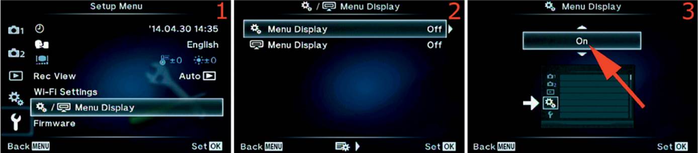
Figure 6.1A: Enabling the Custom Menu
Use these steps to make the Custom Menu visible:
1. Select Menu Display from the Setup Menu and scroll to the right (figure 6.1A, image 1).
2. Choose the top menu selection, which is the gear symbol followed by Menu Display, then scroll to the right (figure 6.1A, image 2).
3. Press up or down on the Arrow pad until On appears in the up/down menu (figure 6.1A, image 3, red arrow).
4. Press the OK button to Set the Custom Menu so it will display on the menu system.
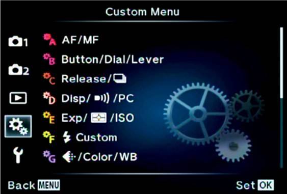
Figure 6.1B: The Custom Menu
When the Custom Menu is enabled, it is the fourth menu down on the left side of the menu system screen (figure 6.1B).
The Custom Menu is composed of 11 major sections (A–K), with many individual functions under each section. We will consider each of the functions in detail. Here is a look at the Custom Menu after it has been enabled.
Now, let’s see how each of the functions in the Custom Menu work.
Custom Menu A. AF/MF
The AF/MF function gives you complete control over the autofocus and manual focus capabilities of your camera. You will find these functions under the A. AF/MF heading, as shown in figure 6.2.
AF Mode
AF Mode allows you to choose the type of focus when you take still pictures and shoot videos. Each of the two modes—still pictures and video—can have its own focus settings that are independent of the other. There are five focus settings available for either mode:
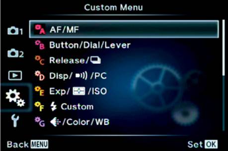
Figure 6.2: The opening menu selection for the A. AF/MF functions
AF Mode focus settings
• S-AF: When you press the Shutter button halfway down, the camera focuses on the subject, locks the focus, and sounds a beep. The green AF Area Pointer will be displayed, and a small green dot (AF confirmation mark) will appear in the top-right corner of the monitor when focus is confirmed. This type of focus is best for subjects that are not moving or are moving very slowly. The camera does not update the focus unless you release the Shutter button and reapply pressure. When you shoot video, no beep or focus indicators will sound or display on the monitor.
• C-AF: As long as you continuously hold the Shutter button halfway down, the camera will continuously update the focus as long as you or the subject are moving. When it can acquire focus, the camera will beep and the green AF confirmation mark (dot) will display without blinking. If you or the subject start moving, the camera will notice the movement and attempt to update the focus. It will beep each time it locks focus on the subject, up to twice, then it stops the beep so it doesn’t become a nuisance in a quiet environment. The difference between S-AF and C-AF is that S-AF does not update focus, while C-AF causes the focus to continuously update. When you are shooting a video, no beep or focus indicators will sound or display on the monitor.
• MF: You must use the focus ring on the lens to focus manually when this mode is enabled. Autofocus is disabled and you are responsible for focusing. This mode is often used by people who shoot macro (closeup) still images and videos to increase the reliability of focusing.
• S-AF+MF: This mode works exactly the same as the S-AF mode. The only difference is that S-AF does not let you fine-tune autofocus with the manual focus ring, while S-AF+MF does. You can let the camera autofocus and then manually adjust the focus yourself, with the focus ring on the lens. If you have focus Peaking enabled (A. AF/MF > MF Assist > Peaking), a white outline will be displayed on the edges of your image, to help you fine-tune the focus.
• C-AF+TR: This mode makes the camera sensitive to moving subjects. Select the subject by pressing the Shutter button halfway until focus locks on the subject. The AF Area Pointer will change from its normal small green rectangle to a much larger square with a line sticking out of each side (figure 6.3C, image 2). As the subject moves, the camera will maintain focus and track it across the viewfinder or monitor. As long as the AF Area Pointer remains green, the camera is tracking; if it turns red, the camera has lost the subject and you should reaquire it by refocusing until the focus locks and tracks again. How well the camera can track a moving subject when other objects intervene is controlled by the C-AF Lock function that is considered later in this chapter section. When you shoot a video, the camera will not beep, but it will display the tracking AF Area Pointer so you will know that it is tracking successfully.
Now, let’s see how to select your favorite focus mode for both still pictures and videos.
Still Pictures
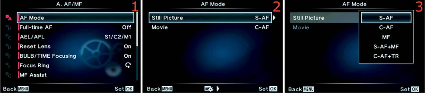
Figure 6.3A: Selecting a focus mode for still pictures
Use these steps to select a focus mode for still pictures:
1. Select AF Mode from the A. AF/MF menu and scroll to the right (figure 6.3A, image 1).
2. Choose Still Picture from the AF Mode menu and scroll to the right (figure 6.3A, image 2).
3. A menu will appear with five focus mode choices. Refer to the AF Mode focus settings list and select the mode you want to use (figure 6.3A, image 3).
4. Press the OK button to Set the mode. Now, take your pictures.
Movie
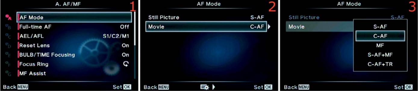
Figure 6.3B: Selecting a focus mode for movies
Use these steps to select a focus mode for movies:
1. Select AF Mode from the A. AF/MF menu and scroll to the right (figure 6.3B, image 1).
2. Choose Movie from the AF Mode menu and scroll to the right (figure 6.3B, image 2).
3. A menu will appear with five focus mode choices. Refer to the AF Mode focus settings list and select the mode you want to use (figure 6.3B, image 3).
4. Press the OK button to Set the mode. Now, make your movie.
AF Area Pointers
When you use the modes in the autofocus system, you will see a focus point indicator in the viewfinder or on the monitor. This indicator tells you what the camera is focused on. It is called the AF Area Pointer.
The AF Area Pointer is a small green rectangle (Single Target) or a small square (Small Target) for normal focus, a green square with lines for focus tracking, or a large or small green square for face and eye recognition modes.
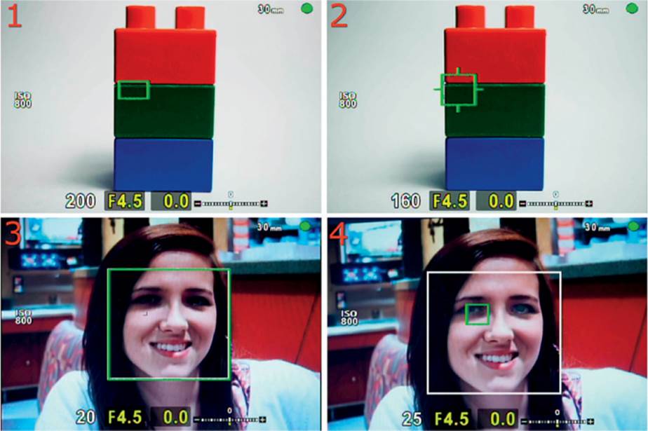
Figure 6.3C: Enabling or disabling the AF Area Pointer
Here are the types of AF Area Pointers that are shown in figure 6.3:
• The Single Target AF Area Pointer is a small green rectangle that you will see in various AF modes, such as S-AF and C-AF (figure 6.3C, image 1). This AF Area Pointer is also available in a smaller version (Small Target), which allows finer AF points for more detailed autofocus.
• The AF tracking symbol will appear when you use your camera to track a subject C-AF+TR mode (figure 6.3C, image 2).
• In Face Priority (see Note), a large white square is overlaid with a green focus-confirmation square of the same size. Sometimes the white face-tracking square and the green focus-confirmation square are slightly offset (figure 6.3C, image 3).
• In Face Priority (see Note), a larger face-tracking white square and a smaller green eye-detection AF confirmation square appear over the subject’s eye on the left side of the frame (figure 6.3C, image 4).
Note: The larger squares shown in figure 6.3C, images 3 and 4, will appear instead of the Single Target or Small Target AF Area Pointers when you have one of the Face Priority modes enabled and a detectable human face is in the subject area. We will consider the Face Priority modes in an upcoming section.
With Face Priority enabled and when no people are in the subject area, the camera will use its normal AF Area Pointers and switch to the larger Face Priority squares only if a human face is detected.
If you want the camera to ignore human faces so you can use the normal AF Area Pointers all the time, you can disable Face Priority. We will consider how to use Face Priority in the upcoming subsection titled Face Priority on page 291.
Settings Recommendation: For everyday shooting of still pictures, the S-AF mode works well. If the subject is moving erratically, it may be a good idea to use C-AF. I leave my camera set to S-AF+MF most of the time because, as a nature photographer, I find that it allows me the most flexibility. I can use autofocus and then fine-tune it for things like macro shots or portraits in nature.
When I am shooting video I often use C-AF, but I find myself helping a little from time to time by pressing the Shutter button halfway down to force an AF operation. Many serious videographers like to use MF so they can have full control of what is in focus.
When I shoot sports or action, I often use C-AF and Sequential L mode so I can get good focus updating on my subjects. When I shoot wildlife, I often use C-AF+TR and Sequential L mode to track an animal as it moves around, especially for creatures like flying birds. Sequential L mode fires at 6.5 fps with firmware 2.0 or 9 fps with firmware 3.0.
Using the 10 fps Sequential H mode is not a great idea for many moving subjects because the camera cannot update the autofocus at that speed. However, if the subject is moving parallel to you, such as a race car, you may be able to use the 10 fps mode since the focus locks on the first frame and the distance to the subject does not vary greatly. If the aperture is small enough, the depth of field may cover most focus errors.
Full-Time AF
Full-Time AF is similar to C-AF, except the camera does not require you to press the Shutter button to initiate autofocus. Instead, the camera decides what the subject is and does its best to maintain focus on it without your assistance.
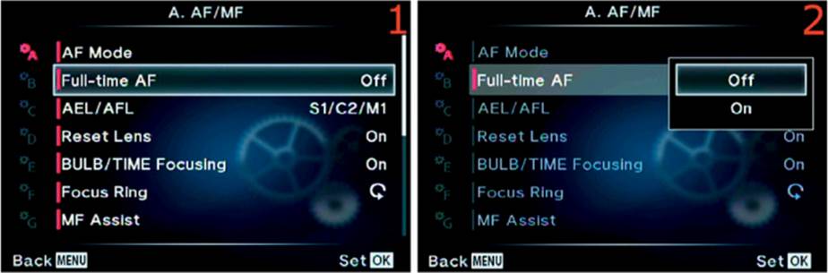
Figure 6.4: Enabling Full-Time AF
Use these steps to enable or disable Full-Time AF:
1. Choose Full-Time AF from the A. AF/MF menu and scroll to the right (figure 6.4, image 1).
2. A menu will open that has two choices: Off and On. Choose On to enable Full-Time AF, and choose Off to keep it disabled (figure 6.4, image 2).
3. Press the OK button to Set your choice.
Note: Full-Time AF does not work with Four Thirds lenses and an MMF adapter (Olympusbrand adapter for converting a Four Thirds lens for use on a Micro Four Thirds body). The camera will use Micro Four Thirds lenses only for this mode.
Settings Recommendation: This mode will work best when the subject is large in the frame and has plenty of contrast between itself and the background. If your subject is in an area with lots of bright, high-contrast items, the camera may have a hard time keeping the subject in focus because it gets distracted by other objects.
I rarely use this mode because I simply don’t trust any camera to decide what I want to have in focus. Instead, I use one of the A. AF/MF modes considered in the previous subsection.
This mode may be useful if you hand your camera to your grandmother to take pictures and she has never used a mirrorless interchangeable-lens camera before.
AEL/AFL
The AEL/AFL button allows you to control AEL (autoexposure lock) and AFL (autofocus lock). The AEL/AFL button has a strong relationship with the Shutter button. The camera allows you to configure various combinations of the two buttons to accomplish different methods of locking exposure, autofocus, and taking a picture.
There are three focus modes that we must consider: single AF (S-AF), continuous AF (C-AF), and manual focus (MF). We will configure the AEL/AFL button and Shutter button for each focus mode.
First, select a focus mode (S-AF, C-AF, or MF) from the AF Mode function. Second, configure the AEL/AFL button and Shutter button relationship for the focus mode you just chose. (See the previous AF Mode subheading for AF Mode selection.)
There are three combination modes available for the AEL/AFL button and Shutter button when you use S-AF and MF: mode1, mode2, and mode3. When you use C-AF mode, a fourth mode, mode4, is also available.
Let’s consider these button combination modes for each focus mode.
S-AF Mode
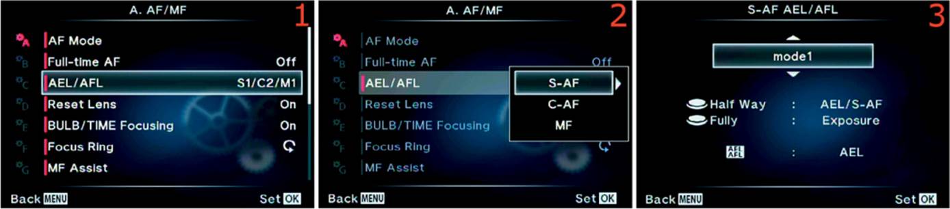
Figure 6.5A: AEL/AFL button and Shutter button relationship in S-AF focus mode
Use the following steps to configure the relationship of the AEL/AFL and Shutter buttons when you select S-AF focus mode:
1. Select AEL/AFL from the A. AF/MF menu and scroll to the right (figure 6.5A, image 1).
2. A menu with three choices will appear: S-AF, C-AF, or MF. Choose S-AF and scroll to the right (figure 6.5A, image 2).
3. An up/down menu will appear with the choices of mode1, mode2, or mode3 (figure 6.5A, image 3). Below the up/down menu is a short description of what each mode does. Here are better descriptions of what the AEL/AFL and Shutter buttons do in each mode:
a. mode1
• Shutter button: Pressing the Shutter button Half Way provides autoexposure lock (AEL) and single AF (S-AF) autofocus. Pressing the Shutter button Fully takes the picture (Exposure).
• AEL/AFL button: Pressing the AEL/AFL button toggles autoexposure lock (AEL).
b. mode2
• Shutter button: Pressing the Shutter button Half Way provides single AF (S-AF) autofocus. Pressing the Shutter button Fully provides autoexposure lock (AEL) and takes the picture (Exp).
• AEL/AFL button: Pressing the AEL/AFL button toggles autoexposure lock (AEL).
c. mode3
• Shutter button: Pressing the Shutter button Half Way provides autoexposure lock (AEL). Pressing the Shutter button Fully takes the picture (Exposure).
• AEL/AFL button: Pressing the AEL/AFL button provides single AF (S-AF) autofocus.
4. Scroll up or down with the Arrow pad and select one of the modes. Press the OK button to Set it. Now, whenever you choose S-AF or S-AF+MF from the AF Mode menu, your camera will use the relationship mode you chose.
C-AF Mode
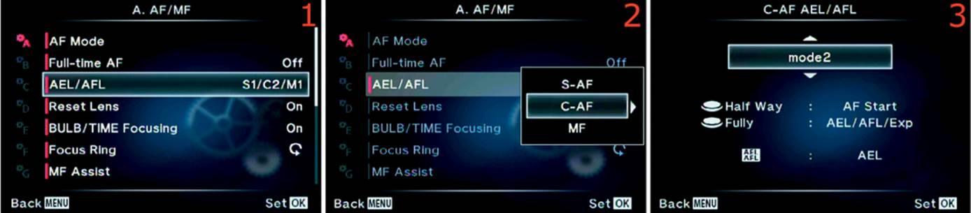
Figure 6.5B: AEL/AFL button and Shutter button relationship in C-AF focus mode
Use the following steps to configure the relationship of the AEL/AFL and Shutter buttons when you select C-AF focus mode:
1. Select AEL/AFL from the A. AF/MF menu and scroll to the right (figure 6.5B, image 1).
2. A menu with three choices will appear: S-AF, C-AF, or MF. Choose C-AF and scroll to the right (figure 6.5B, image 2).
3. An up/down menu will appear with the choices of mode1, mode2, mode3, or mode4 (figure 6.5B, image 3). Below the up/down menu is a short description of what each mode does. Here are better descriptions of what the AEL/AFL and Shutter buttons do in each mode:
a. mode1
• Shutter button: Pressing the Shutter button Half Way provides autoexposure lock (AEL) and starts continuous AF (C-AF) autofocus. Pressing the Shutter button Fully locks autofocus (AFL) and takes the picture (Exp).
• AEL/AFL button: Pressing the AEL/AFL button toggles autoexposure lock (AEL).
b. mode2
• Shutter button: Pressing the Shutter button Half Way starts continuous AF (C-AF) autofocus. Pressing the Shutter button Fully provides autoexposure lock (AEL), autofocus lock (AFL), and takes the picture (Exp).
• AEL/AFL button: Pressing the AEL/AFL button toggles autoexposure lock (AEL).
c. mode3
• Shutter button: Pressing the Shutter button Half Way provides autoexposure lock (AEL). Pressing the Shutter button Fully provides autofocus lock (AFL) and takes the picture (Exp).
• AEL/AFL button: Pressing the AEL/AFL button starts continuous AF (C-AF) autofocus.
d. mode4
• Shutter button: Pressing the Shutter button Half Way does nothing. Pressing the Shutter button Fully provides autoexposure lock (AEL), autofocus lock (AFL), and takes the picture (Exp).
• AEL/AFL button: Pressing the AEL/AFL button starts continuous AF (C-AF) autofocus.
4. Scroll up or down with the Arrow pad and select one of the modes. Press the OK button to Set it. Now, whenever you choose C-AF or C-AF+TR from the AF Mode menu, your camera will use the relationship you chose.
MF Mode
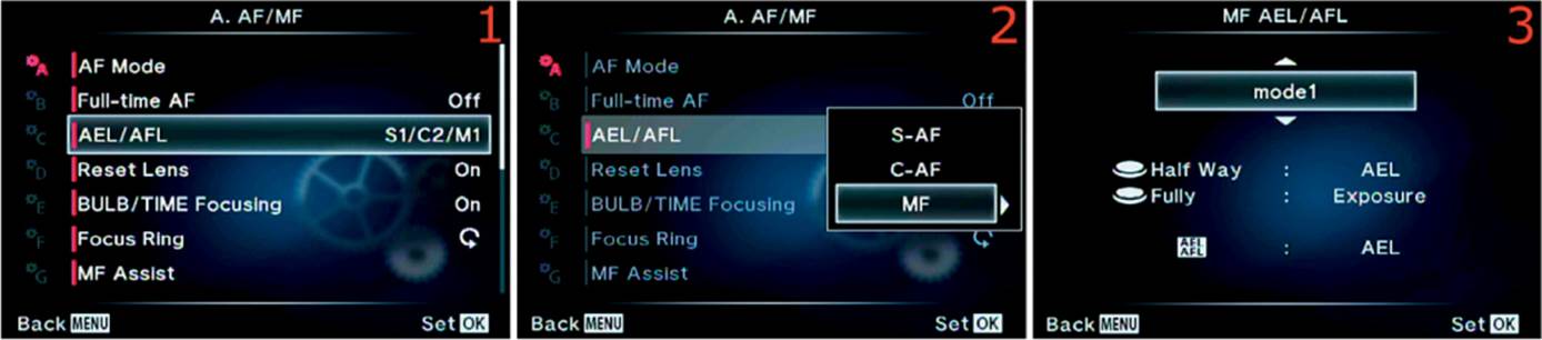
Figure 6.5C: AEL/AFL button and Shutter button relationship in MF focus mode
Use the following steps to configure the relationship of the AEL/AFL and Shutter buttons when you select MF focus mode:
1. Select AEL/AFL from the A. AF/MF menu and scroll to the right (figure 6.5C, image 1).
2. A menu with three choices will appear: S-AF, C-AF, or MF. Choose MF and scroll to the right (figure 6.5C, image 2).
3. An up/down menu will appear with the choices of mode1, mode2, or mode3 (figure 6.5C, image 3). Below the up/down menu is a short description of what each mode does. Here are better descriptions of what the AEL/AFL and Shutter buttons do in each mode:
a. mode1
• Shutter button: Pressing the Shutter button Half Way provides autoexposure lock (AEL). You must manually focus the lens. Pressing the Shutter button Fully takes the picture (Exposure).
• AEL/AFL button: Pressing the AEL/AFL button toggles autoexposure lock (AEL).
b. mode2
• Shutter button: Pressing the Shutter button Half Way does nothing, and you must manually focus the lens. Pressing the Shutter button Fully provides autoexposure lock (AEL) and takes the picture (Exp).
• AEL/AFL button: Pressing the AEL/AFL button toggles autoexposure lock (AEL).
c. mode3
• Shutter button: Pressing the Shutter button Half Way provides autoexposure lock (AEL), and you must manually focus the lens. Pressing the Shutter button Fully takes the picture (Exposure).
• AEL/AFL button: Pressing the AEL/AFL button provides single AF (S-AF) autofocus.
4. Scroll up or down with the Arrow pad and select one of the modes. Press the OK button to Set it. Now, whenever you choose MF or S-AF+MF from the AF Mode menu, your camera will use the relationship mode you chose.
Back-Button Focus Using the AEL/AFL Button
The E-M1 can provide back-button focus for people who want to separate the autofocus and shutter-release actions that are normally assigned to the Shutter button. The configuration steps for S-AF, C-AF, and MF modes are as follows:
Single AF (S-AF) mode
1. Set Custom Menu > A. AF/MF > AF Mode > Still Picture to S-AF.
2. Set Custom Menu > A. AF/MF > AEL/AFL > S-AF to mode3.
Continuous AF (C-AF) mode
1. Set Custom Menu > A. AF/MF > AF Mode > Still Picture to C-AF.
2. Set Custom Menu > A. AF/MF > AEL/AFL > C-AF to mode4.
Manual focus (MF) mode
1. Set Custom Menu > A. AF/MF > AF Mode > Still Picture to MF.
2. Set Custom Menu > A. AF/MF > AEL/AFL > C-AF to mode3.
Note: The Shutter button will not initiate autofocus when you set the camera to manual focus (MF) mode; this allows you to use the manual focus ring on your lens for precise focusing. To enable back-button focus in manual focus (MF) mode, you can use single AF (S-AF) by pressing the AEL/AFL button. This gives you the best of both worlds: full manual focus and autofocus on demand.
For all three focus modes, the Shutter button will not start autofocus; instead, it will initiate AEL, AFL (or both), and/or shutter release only. The AEL/AFL button will provide autofocus in this manner: single AF for S-AF and MF focus modes, and continuous AF for C-AF focus mode.
Settings Recommendation: Because I am a nature photographer, I do not use back-button focus very often. When I am shooting nature, events, or portraits and use the Shutter button for focus, I configure my AEL/AFL settings this way: S-AF mode: mode1; C-AF mode: mode2; and MF mode: mode3.
If you want to use back-button focus instead of Shutter button focus, use these settings: S-AF mode: mode3; C-AF mode: mode3 or mode4; and MF mode: mode3.
Reset Lens
Reset Lens is a simple function that resets the focus of your lens to infinity each time you turn the camera off. It works for both standard zoom and power zoom lenses.
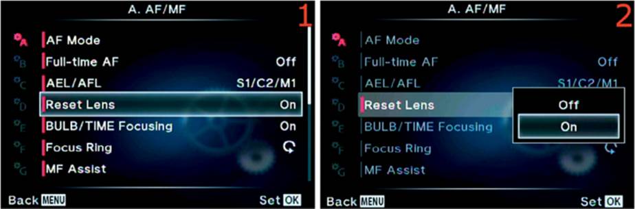
Figure 6.6: Set the lens to infinity when the camera powers off
Use the following steps to enable or disable Reset Lens:
1. Choose Reset Lens from the A. AF/MF menu and scroll to the right (figure 6.6, image 1).
2. A menu will appear with two choices: On and Off (figure 6.6, image 2). Choose On to reset the lens to infinity when the camera powers off, or select Off to retain the focus position of the lens when the camera powers off. This function will have no effect on manual focus lenses.
3. Press the OK button to Set the choice.
Settings Recommendation: I leave this feature On. Why not focus the lens to infinity when the camera is turned off? This setting will not affect the zoom setting of the lens, just its focus position. Manual lenses are not controlled by the camera, so they will not be reset to infinity. If you don’t want your lens to be set to infinity when the camera powers off, leave this setting Off.
BULB/TIME Focusing
When you use Live Time or Live Bulb modes to see a short time-exposure image come up gradually on the monitor, or when you do light writing in an image, the camera normally locks focus during the long exposure when you use manual focus (MF) mode.
If you want to use the focus ring on your lens to update focus during the long exposure, you must set this function to On.
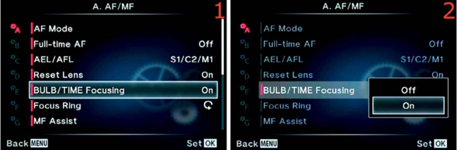
Figure 6.7: Enabling manual focus during Live Time and Live Bulb modes
Use the following steps to enable or disable manual focus during Live Time and Live Bulb operations:
1. Choose BULB/TIME Focusing from the A. AF/MF menu and scroll to the right (figure 6.7, image 1).
2. A menu will appear with two choices: On and Off (figure 6.7, image 2). Choose On to enable manual focus with the lens focus ring, or select Off to disable manual focus during a long exposure.
3. Press the OK button to Set the choice.
Settings Recommendation: I leave BULB/TIME Focusing set to On. When I take a Live Bulb shot, I may want to change the focus slightly to focus on multiple people who are light writing. Why disable something you may need to use, even if only occasionally?
Focus Ring
When you turn the focus ring toward infinity, you normally rotate it counterclockwise (from behind the camera). For a closeup picture (macro), you rotate the focus ring clockwise. If you want to reverse the direction, you can change it with this setting.
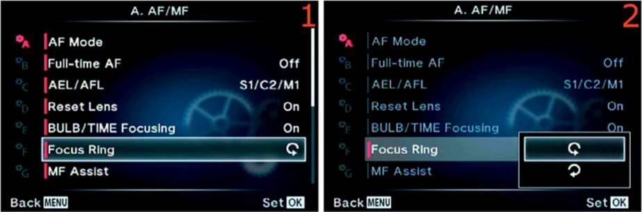
Figure 6.8: Reversing the directional effect of rotating the lens focus ring
Use the following steps to change the directional effect of rotating the lens focus ring:
1. Choose Focus Ring from the A. AF/MF menu and scroll to the right (figure 6.8, image 1).
2. A small menu will appear with two circular arrows that represent rotation directions (figure 6.8, image 2). Choose clockwise or counterclockwise rotation to select the direction you want to turn the lens when you move from infinity to closeup.
3. Press the OK button to Set the choice.
Settings Recommendation: I changed the direction to the opposite of the factory default—clockwise for infinity—so the rotation direction matches my AF-S Nikkor 24–70mm f/2.8G ED lens, which I use on my Nikon D800 (and sometimes, with an adapter, on my E-M1). Why confuse myself by having things work backwards when I switch cameras?
If you do not use lenses from other camera brands that focus in the opposite direction, this function may have little interest to you. However, remember it is there in case you ever want to change it.
MF Assist
MF Assist helps you accurately focus on a subject when you shoot in manual focus (MF) mode. There are two types of MF Assist: Magnify and Peaking.
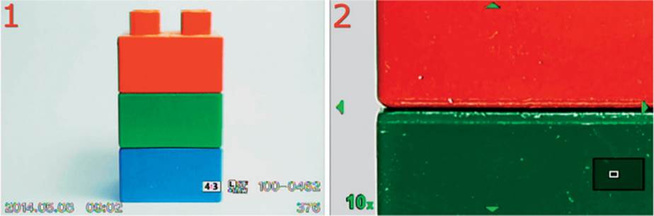
Figure 6.9A: Using Magnify and Peaking to assist with manual focusing
In figure 6.9A, image 1, the subject is red, green, and blue blocks. When the focus ring is turned with both Magnify and Peaking enabled, the camera displays what you see in figure 6.9A, image 2. The camera zooms in by 10x so you can see fine detail and manually focus more easily.
Notice that Peaking is active, as shown by the white outline on the green and red block borders and white dust specks. Peaking emphasizes the in-focus edges of the subject with a white or black tone (depending on the setting at Custom Menu > D. Disp/[Sound]/PC > Peaking Settings) to help you see the exact point of focus. Peaking appears only briefly, while you turn the focus ring, as does the magnification. If you stop focusing for about a half second, both Magnify and Peaking turn off. As soon as you turn the focus ring again, they reappear.
The combination of these methods gives you very fine control over manual focus. Let’s see how to enable and disable the two focus assistance aids.
Magnify
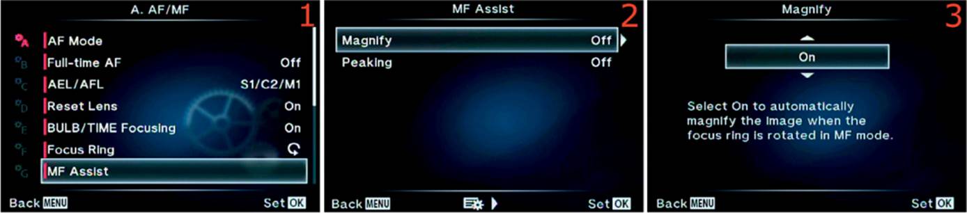
Figure 6.9B: Enabling Magnify to assist with manual focusing
Use these steps to enable or disable Magnify for manual focus assistance:
1. Select MF Assist from the A. AF/MF menu and scroll to the right (figure 6.9B, image 1).
2. Choose Magnify and scroll to the right (figure 6.9B, image 2).
3. From the up/down menu, choose On or Off (figure 6.9B, image 3). On enables Magnify and Off disables it.
4. Press the OK button to Set your choice.
Peaking
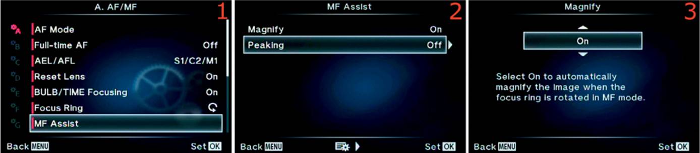
Figure 6.9C: Enabling Peaking to assist with manual focusing
Use these steps to enable or disable Peaking for manual focus assistance:
1. Select MF Assist from the A. AF/MF menu and scroll to the right (figure 6.9C, image 1).
2. Choose Peaking and scroll to the right (figure 6.9C, image 2).
3. From the up/down menu, choose On or Off (figure 6.9C, image 3). On enables Peaking and Off disables it.
4. Press the OK button to Set your choice.
Settings Recommendation: I use both of these functions to assist with manual focus. I leave Peaking On all the time and Magnify On part of the time. Some subjects require both to get accurate focus, others do not. Experiment with both of these focus aids so you will have full control with no other focusing aids.
[•••] Set Home
The [•••] Set Home function works in conjunction with a Button task called [•••] Home. You can store a single autofocus point (AF point) target position from the camera’s 81 AF points in [•••] Set Home. Then, when you assign the [•••] Home function to one of the camera’s buttons (such as Fn1) and press that button, the camera immediately moves the AF Area Pointer (green focus rectangle) to the AF point position stored in [•••] Set Home.
Note: See the Button task called [•••] Home in Appendix: Button Tasks Reference, on page 479, to assign [•••] Home to a camera button.
There are four types of AF point arrangements in the camera, which you can select by having one of the camera buttons assigned to AF Area Select. The four AF Target Types are All Targets, Single Target, Small Target, and Group Target. Information about how they work and how to select one is provided on page 470 under Appendix: Button Tasks Reference and the subheading [•••] AF Area Select.
Additionally, in this chapter subsection, when 81 focus points are mentioned, be aware that this applies only to Micro Four Thirds (m4/3) lenses. If you have an older Four Thirds (4/3) lens mounted with an MMF adapter, the camera will display only 37 focus points.
Let’s see how to store an AF point position from each of the four types of AF points in the [•••] Set Home memory location.
All Targets
The All Targets function allows the camera to decide which AF point target to use for the best autofocus. You will see the AF Area Pointer flash and a beep will sound when the camera chooses a focus target—usually the nearest high-contrast object it can detect, unless Face Priority is enabled and a human face is in the frame, in which case it will select the face.
When you choose All Targets for the [•••] Set Home Task, the camera will use all 81 AF points to detect a subject, and when you press the button assigned to the [•••] Home Task, the 81 focus points will display in green.
You will not choose an individual AF point target since all AF points will be used by the camera for automatic focus selection.
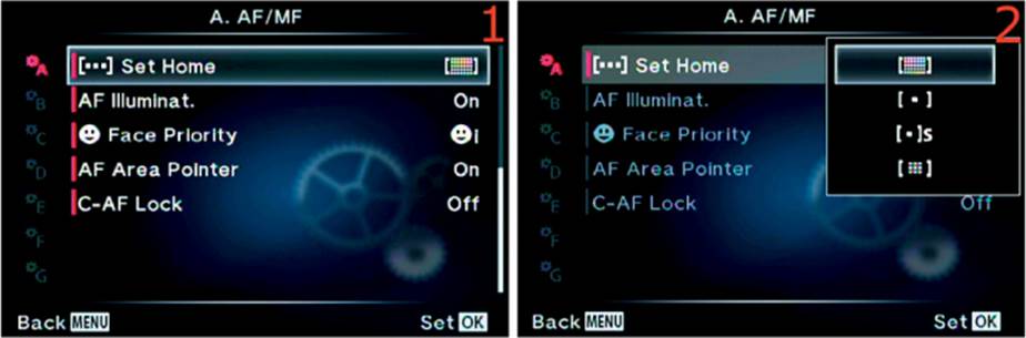
Figure 6.10A: Choosing the All Targets focus system
Use the following steps to select the All Targets focus arrangement:
1. Choose [•••] Set Home from the A. AF/MF menu and scroll to the right (figure 6.10A, image 1).
2. A menu will open and allow you to choose All Targets, which is represented by a small grid in brackets at the top of the menu (figure 6.10A, image 2). All AF points will be active for autofocus (81 AF points with m4/3 lenses, or 37 AF points with 4/3 lenses). There is no single home position when you use All Targets. Therefore, the camera will display all AF points in bright green when you press the button assigned to [•••] Home.
3. Press the OK button to Set the camera to All Targets, with all available AF points in the home position, when you press the button assigned to [•••] Home.
Single Target
The Single Target function allows you to choose a single AF point target that you can scroll around the screen. You can position the AF Area Pointer on the subject for the best autofocus on that specific area.
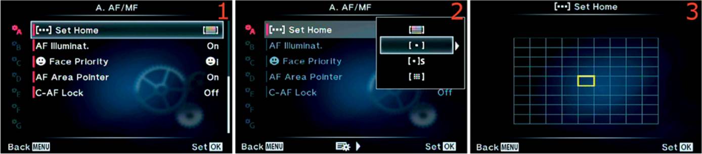
Figure 6.10B: Choosing the [•••] Home position of the Single Target focus system
Use the following steps to select the Single Target focus arrangement and assign a home point (HP) that you can later select by pressing the button assigned to [•••] Home:
1. Choose [•••] Set Home from the A. AF/MF menu and scroll to the right (figure 6.10B, image 1).
2. A menu will open and allow you to choose Single Target, which is represented by single AF point in brackets, second from the top (figure 6.10B, image 2). Scroll to the right.
3. Choose one of the AF point target positions from the grid (81 points with m4/3 lenses and 37 points with 4/3 lenses). I chose the center AF point (figure 6.10B, image 3).
4. Press the OK button to Set the home point for Single Target.
Small Target
Small Target is very similar to Single Target in that you can scroll the AF Area Pointer around within all the focus points on the screen and position it where you want it. The difference is in the size of the AF Area Pointer. It is significantly smaller than the normal green rectangle, which tends to make it more detail sensitive for smaller subjects. If you are doing macro photography and want to focus on a very small area of the subject, this is the best setting.
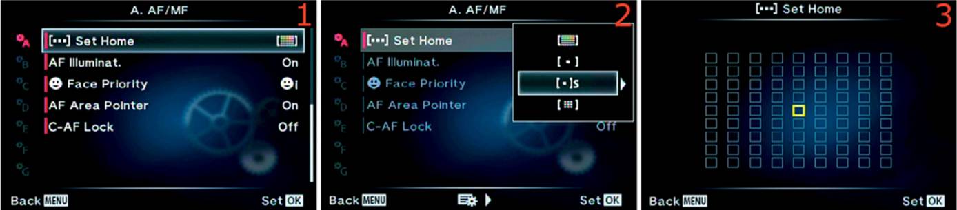
Figure 6.10C: Choosing the [•••] Home position of the Small Target focus system
Use the following steps to choose the Small Target focus arrangement and assign a home point (HP) that you can later select by pressing the button assigned to [•••] Home:
1. Choose [•••] Set Home from the A. AF/MF menu and scroll to the right (figure 6.10C, image 1).
2. A menu will open and allow you to choose Small Target, which is represented by the single AF point in brackets, followed by a small s, third from the top (figure 6.10C, image 2). Scroll to the right.
3. Choose one of the AF point target positions from the grid (81 points with m4/3 lenses and 37 points with 4/3 lenses). I chose the center AF point (figure 6.10C, image 3).
4. Press the OK button to Set the camera’s home point for Small Target.
Group Target
The Group Target setting causes the camera to use an array of nine AF points in a small grid. The camera will decide which of the AF point targets from within the nine-point grid to use for the best focus. You can move the entire nine-point group around within all the focus points on the screen, just like with a single AF point target.

Figure 6.10D: Choosing the [•••] Home position of the Group Target focus system
Use the following steps to choose the Group Target focus arrangement and assign a home point (HP) for the nine-point grid that you can select by pressing the button assigned to [•••] Home:
1. Choose [•••] Set Home from the A. AF/MF menu and scroll to the right (figure 6.10D, image 1).
2. A menu will open and allow you to choose Group Target, which is represented by the small grid in brackets, at the bottom of the menu (figure 6.10C, image 2). Scroll to the right.
3. The Group Target, with nine bright green points, will display on the larger and dimmer grid (81 points with m4/3 lenses and 37 points with 4/3 lenses). I chose the center nine AF points (figure 6.10C, image 3).
4. Press the OK button to Set the camera’s home point for Group Target.
Previously Assigned Home Position (HP)
As shown in figure 6.10E, when you are scrolling around in the AF points during the selection process, after you set a home position, you can identify the AF point that was previously assigned to the home position when HP appears above the grid.
Note: The camera automatically changes the AF Target Type to Single Target when you are shooting a video.
Settings Recommendation: I normally leave my camera set to Single Target with the center AF point set to home position so the AF Area Pointer will jump to the center when I press the button assigned to [•••] Home. If you have special needs, such as if you take vertical portraits frequently and would rather have the AF Area Pointer appear at one end of the 81 (or 37) AF points for vertical face selection, you can choose other settings.
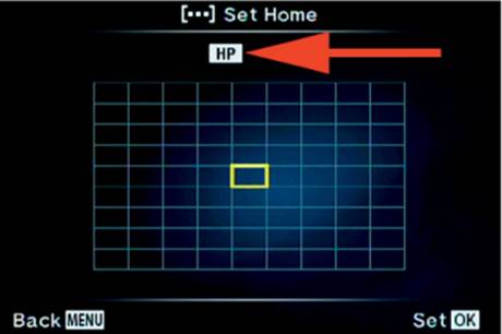
Figure 6.10E: The AF point selection is currently at [•••] HP
Most people leave the center AF point target set at home position, but if you need an off-center AF point to appear when you press the button assigned to [•••] Home, you can configure the camera to make that happen.
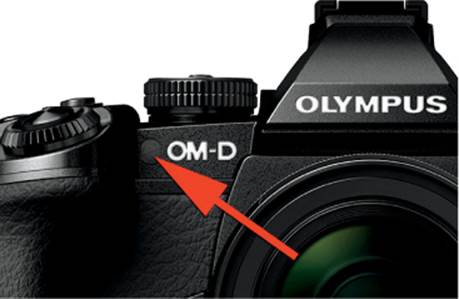
Figure 6.11A: AF Illuminator light location
AF Illuminat.
The AF Illuminator is the small light next to the OM-D label on the front of the camera (figure 6.11A). It shines red when you start autofocus in a dark area. The light assists the camera by shining on nearby objects.
The light may be distracting sometimes, so you can turn it Off with the AF Illuminat. function.

Figure 6.11B: Enabling or disabling the AF Illuminator light
Use these steps to control whether the AF Illuminator light is On or Off:
1. Choose AF Illuminat. from the A. AF/MF menu and scroll to the right (figure 6.11B, image 1).
2. A menu will open with two choices: On and Off (figure 6.11B, image 2). Choose On to allow the light to assist with autofocus, or choose Off to disable the light.
3. Press the OK button to Set your choice.
Settings Recommendation: When I am shooting in an environment where people will not appreciate a shining light, such as at some very traditional weddings, or if I am trying to sneak some pictures and don’t want to call attention to myself, I disable the light.
The camera senses when the light is low enough that the AF Illuminator is needed. The light doesn’t shine when the ambient light is bright or when you use a flash unit that has a built-in assist light. Therefore, most of the time I leave AF Illuminat. set to On.
![]() Face Priority
Face Priority
Face Priority is a very efficient and accurate human face detection system that is built into the camera. It tells the camera to watch for human faces and, if found, make them the priority for accurate autofocus.
When you are shooting nonhuman subjects the camera works normally and displays a regular green AF Area Pointer as it focuses. However, when the camera detects human faces, it switches all its attention to the faces and uses a much larger white AF square (figure 6.12A).
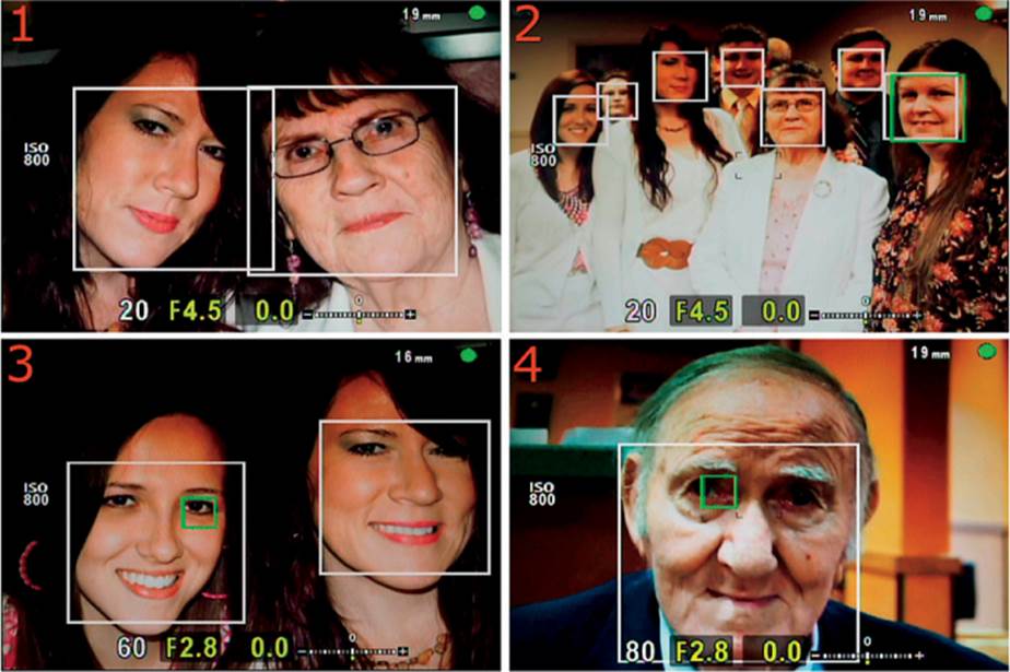
Figure 6.12A: Using Face Priority
Notice how all the faces in figure 6.12A are surrounded by the white face-tracking square. The white squares tend to stay with detected faces as they move, so they’ll jump a little as the camera keeps track of detected faces. The white squares are not really in-focus indicators; they merely show the location of a face in the subject area.
When focus initially locks on a face, a separate green focus-confirmation square—the same size as the white square—will appear briefly, along with a beep from the camera. You can see both the white and green AF squares in figure 6.12A, image 2, surrounding the face of the lady on the far right. The green focus-confirmation square is slightly offset from the white face-tracking square.
Figure 6.12A, images 3 and 4, show a tiny green square surrounding an eye. This tiny green eye-focus confirmation square appears briefly when Eye Priority is enabled and focus has locked on an eye. Which eye it locks on is controlled by which Face Priority mode is enabled, as described in the upcoming Face Priority types list.
Note that an AF confirmation mark (small green dot) appears in the top-right corner of the viewfinder or monitor when focus has locked on the subject. You can see the green AF confirmation mark (dot) in the top-right corner of all four images in figure 6.12A, showing that the AF system has focused.
Here are the four Face Priority modes (plus Off) and descriptions of how they work:
Face Priority types
• ![]() (Face Priority On): This setting causes the camera to seek human faces and give them autofocus priority (figure 6.12A, image 1). Notice how both faces have a white face-tracking square surrounding them. The camera will find and frame each face it detects and try to balance autofocus on the faces depending on which AF mode is selected (e.g., S-AF or C-AF).
(Face Priority On): This setting causes the camera to seek human faces and give them autofocus priority (figure 6.12A, image 1). Notice how both faces have a white face-tracking square surrounding them. The camera will find and frame each face it detects and try to balance autofocus on the faces depending on which AF mode is selected (e.g., S-AF or C-AF).
• ![]() i (Face Priority and Eye Priority On): This setting causes the camera to seek a pupil in the eye of the closest human face and give that face autofocus priority (figure 6.12A, image 2). The lady on the right side of the group has the primary point of focus because she is closest to the camera. You can tell that she is the point of focus because the green focus confirmation square is displayed along with the white face-tracking square. The camera has found every face in the seven-person group and has surrounded each one with a white face-tracking square. The camera uses the autofocus mode that is currently selected (e.g., S-AF or C-AF).
i (Face Priority and Eye Priority On): This setting causes the camera to seek a pupil in the eye of the closest human face and give that face autofocus priority (figure 6.12A, image 2). The lady on the right side of the group has the primary point of focus because she is closest to the camera. You can tell that she is the point of focus because the green focus confirmation square is displayed along with the white face-tracking square. The camera has found every face in the seven-person group and has surrounded each one with a white face-tracking square. The camera uses the autofocus mode that is currently selected (e.g., S-AF or C-AF).
• ![]() iR (Face Priority and R. Eye Priority On): This setting causes the camera to seek the pupil on the right side of the frame and give it autofocus priority (figure 6.12A, image 3). You will see the small green eye-focus confirmation square appear briefly, and the camera will beep when focus has locked on an eye. The camera uses the autofocus mode that is currently selected (e.g., S-AF or C-AF).
iR (Face Priority and R. Eye Priority On): This setting causes the camera to seek the pupil on the right side of the frame and give it autofocus priority (figure 6.12A, image 3). You will see the small green eye-focus confirmation square appear briefly, and the camera will beep when focus has locked on an eye. The camera uses the autofocus mode that is currently selected (e.g., S-AF or C-AF).
• ![]() iL (Face Priority and L. Eye Priority On): This setting causes the camera to seek the pupil on the left side of the frame and give it autofocus priority (figure 6.12A, image 4). You will see the small green eye-focus confirmation square appear briefly. The camera uses the autofocus mode that is currently selected (e.g., S-AF or C-AF).
iL (Face Priority and L. Eye Priority On): This setting causes the camera to seek the pupil on the left side of the frame and give it autofocus priority (figure 6.12A, image 4). You will see the small green eye-focus confirmation square appear briefly. The camera uses the autofocus mode that is currently selected (e.g., S-AF or C-AF).
• ![]() OFF (Face Priority Off): This setting disables human face-detection autofocus priority and uses normal autofocus.
OFF (Face Priority Off): This setting disables human face-detection autofocus priority and uses normal autofocus.
Let’s see how to enable Face Priority. Most photographers leave it enabled all the time.
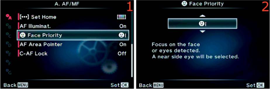
Figure 6.12B: Enabling Face Priority face detection
1. Choose ![]() Face Priority from the A. AF/MF menu and scroll to the right (figure 6.12B, image 1).
Face Priority from the A. AF/MF menu and scroll to the right (figure 6.12B, image 1).
2. An up/down menu will open with the five choices shown in the Face Priority types list (figure 6.12B, image 2). Choose one of the face detection methods or Off. I chose Face Priority and Eye Priority (![]() i).
i).
3. Press the OK button to Set the face detection type.
Note: When Face Priority is enabled and when no people are in the subject area, the camera will use its normal AF Area Pointers and switch to the larger Face Priority squares only if a human face is suddenly detected.
If you want your camera to ignore human faces so you can use the normal AF Area Pointers all the time, set Face Priority to Off.
Settings Recommendation: Face detection works very well in this camera. When I am using any form of face detection, autofocus still works just as well for normal autofocus without face detection when no people are present in the image. Therefore, I see no reason to turn it off for the type of photography I do (primarily nature). If a person is in the subject area, I want their face to take autofocus priority—that is, if I am interested in photographing the person.
There may be times when you want the camera to ignore faces, then Face Priority would be an aggravation. If you are trying to photograph a nonhuman subject while humans happen to be in the frame, and if the camera is paying undue attention to the human faces, turn Face Priority Off. When this setting is On, the camera is very persistent about focusing on human faces.
The factory default is for Face Priority to be enabled because so many photographers love people photography.
AF Area Pointer
The AF Area Pointer is green rectangles or squares, of various sizes, that signify when and where the camera has achieved autofocus. You can turn the AF Area Pointer On or Off with this function.
Notice that the current position of the AF Area pointer has very faint black corner brackets where it will display the green AF Area Pointer when focus is locked. The brackets go away when AF Area Pointer is set to Off. However, the green square with lines for focus-tracking mode (C-AF+TR) and the white face-tracking square for face detection (Face Priority) cannot be disabled.
Let’s see how to enable or disable the standard green symbol for the AF Area Pointer.
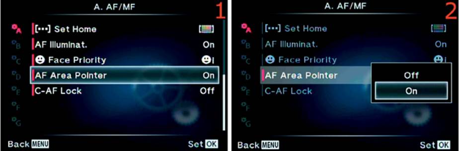
Figure 6.13B: Enabling or disabling the AF Area Pointer
Use these steps to turn the AF Area Pointer On or Off:
1. Choose AF Area Pointer from the A. AF/MF menu and scroll to the right (figure 6.13, image 1).
2. A menu will open with two choices: On and Off (figure 6.13, image 2). Choose On to allow the AF Area Pointer to flash green on the area that is in focus, or choose Off to make it disappear. With no AF Area Pointer enabled, you will have to depend on the round green AF confirmation mark, in the top-right corner of the screen, or the focus beep to tell you when the subject is in focus.
3. Press the OK button to Set your choice.
Settings Recommendation: The AF Area Pointer is not a distraction to me at all. I use it to set the area I want to focus by moving it around within the 81 focus points on my camera screen. When I initiate autofocus, I like that it flashes green when the subject is in focus and that it’s backed up by the AF confirmation mark (green dot) and beep.
With the AF Area Pointer, I know which area of the subject the camera is focusing on. I find it extremely useful. However, if you are simply using your camera as an expensive point-and-shoot, or if the AF Area Pointer interferes with viewing the subject in some way, such as in extreme macro shooting, by all means disable it. Most photographers leave it enabled.
C-AF Lock
The C-AF Lock function controls the amount of time the camera waits after it has lost a subject it was tracking before the AF system moves on to another subject.
With C-AF set to Off, the camera will instantly switch to a different subject if it loses the subject it was tracking. With it set to Low, Normal, or High, the camera waits longer periods of time before switching to a new subject.
Having C-AF Lock set to Off is not good for tracking subjects such as flying birds or people playing sports. If the subject is temporarily blocked by an intruding object, the camera will immediately find another subject to focus on and track. For shooting action you will need to experiment with Low, Normal, and High to see which is most useful. Even at High, the camera seems to wait only about two seconds before it switches to a new subject. That short amount of time may allow you to continue tracking a subject that has temporarily become obscured.
Let’s see how to select the C-AF Lock modes.
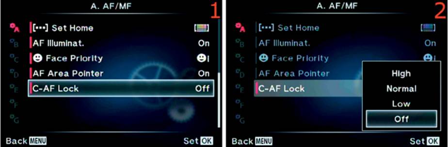
Figure 6.14: Using C-AF Lock
Use these steps to turn the AF Area Pointer On or Off:
1. Choose C-AF Lock from the A. AF/MF menu and scroll to the right (figure 6.14, image 1).
2. A menu will open with four choices: High, Normal, Low, and Off (figure 6.14, image 2). Choose Off to disable the hesitation in continuous subject tracking mode (C-AF+TR). To introduce longer delays before the camera loses tracking on a moving subject when an object gets between you and the subject, use Low, Normal, or High, in that order, to increase the delay time from about 1 second (Low) to 1.5 seconds (Normal) or 2 seconds (High).
3. Press the OK button to Set your choice.
Settings Recommendation: This function is most useful to me when I am using continuous AF subject tracking (C-AF+TR).
Even though the E-M1 user’s manual implies that C-AF Lock works when you use C-AF mode alone, it does not seem to me that the camera hesitates before it switches to a different subject. Why would you want it to hesitate? That seems to defeat the purpose of continuous autofocus. Experiment with the setting and see if you find the same thing.
I do see a difference when C-AF+TR is enabled. There is a definite delay before the camera gives up on tracking a subject when C-AF Lock is set to High. When I use this function in C-AF+TR (continuous subject tracking) mode, I want my camera to stay with the subject I am tracking; therefore, I leave my E-M1 set to High C-AF Lock all the time.
If a second or two of delay is too much for a lost subject and you want your camera to switch to a new subject more quickly, try Low or Normal C-AF Lock—or even Off. This function definitely requires experimentation with the type of action photography you do.
Custom Menu B. Button/Dial/Lever
The B. Button/Dial/Lever menu (figure 6.15) has 28 tasks that you can assign to one of the Button functions on the camera and 6 tasks that you can assign to the Lever function on the back of the camera, some of which involve settings that you adjust with the Front and Rear Dials. These dials can be configured to work in various ways. The E-M1 is one of the most configurable cameras I have ever seen, and this section is one of the primary reasons I say that.
First let’s look at how to open the Button/Dial/Lever functions on the Custom Menu screen, then we will consider how to assign tasks to the Button/Dial/Lever functions. Descriptions of the Button tasks are provided in the appendix, Button Tasks Reference.
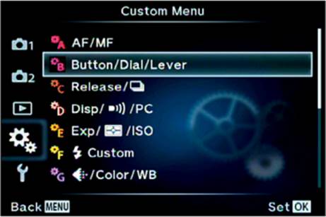
Figure 6.15: The opening menu selection for the B. Button/Dial/Lever functions
Important Naming Information
Olympus uses unusual names for the buttons, dials, and levers on the OM-D E-M1. For instance, you can see in the following images that a button is not just called a button, it is called a Button function (e.g., Fn1, Fn2). There are also Dial functions (e.g., P, A, S, M) and Lever functions (e.g., mode1, mode2).
You can assign certain actions to Button, Lever, and Dial functions. To prevent confusion, I will call the assignable action items “tasks.” Some examples of Button function tasks are HDR, ISO, BKT, and WB.
For example, the Fn1 function can have the WB task assigned to it. When you press the Fn1 button, the camera will allow you to adjust the White balance (WB). At the same time you could assign the Multi Function task to the Fn2 function.
Figure 6.15 displays the B. Button/Dial/Lever selection on the Custom Menu. All the tasks you can assign to the Button, Dial, and Lever functions are available in this menu (see Appendix: Button Tasks Reference). To access them, choose B. Button/Dial/Lever and press the OK button, or scroll to the right with the Arrow pad.
Note: Please make sure your E-M1 is using firmware version 2.0 (or later). Otherwise some of the Button tasks we will discuss in this section and in the Appendix will not appear on your camera’s menus.
Button Function (Programmable Buttons)
The Button functions are a group of 11 programmable button functions (e.g., Fn1 Function, Fn2 Function). There are 28 available Button tasks that can be assigned to the 11 Button functions. Not all Button functions can use all 28 Button tasks. You will find information for the 28 assignable Button tasks in the appendix, Button Tasks Reference. Let’s examine each of the 11 Button functions.
Fn1 Function
The Fn1 button can accept the assignment of most tasks in the Button Tasks List in Appendix: Button Tasks Reference on page 469. The default factory assignment for the Fn1 Function is [•••] AF Area Select.
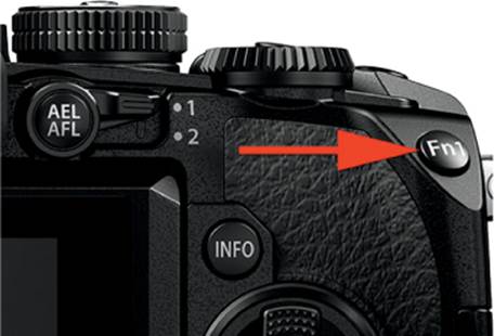
Figure 6.16A: The location of the Fn1 button
First let’s find the Fn1 button on the camera body (figure 6.16A).
Next let’s consider how to use the menus to assign one of the Button tasks to the Fn1 Button function.
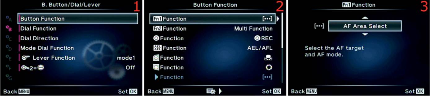
Figure 6.16B: Assigning a Button task to the Fn1 Button function
Use the following steps to assign one of the Button tasks to the Fn1 Button function:
1. Choose Button Function from the B. Button/Dial/Lever menu and scroll to the right (figure 6.16B, image 1).
2. Select Fn1 Function from the Button Function menu and scroll to the right (figure 6.16B, image 2).
3. Choose one of the available Button tasks from the up/down menu (figure 6.16B, image 3). Use the Button Tasks List found in Appendix: Button Tasks Reference to decide which task you will assign to the Fn1 button.
4. Press the OK button to Set the tasks for the Fn1 button.
Settings Recommendation: As mentioned previously, the default assignment for the Fn1 Button function is the [•••] AF Area Select Button task. That is a useful task, and many people will use the default setting. If you have a PRO lens with an L-Fn button, an alternate choice is to use ISO on Fn1. I have the M.Zuiko PRO 12–40mm f/2.8 ED lens, which has an L-Fn button. I assigned the [•••] AF Area Select task to the L-Fn function on my lens because my hand is on the lens during focusing and zooming, and I can easily select the AF area I want to use. I constantly adjust the ISO and want to access it easily, so I set my Fn1 button to ISO.
Fn2 Function
The Fn2 button can accept most task assignments shown in the Button Tasks List in Appendix: Button Tasks Reference on page 469. The default factory assignment for the Fn2 Button function is the Button task named Multi Function.
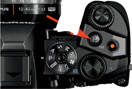
Figure 6.16C: The location of the Fn2 button
First let’s find the Fn2 button on the camera body (figure 6.16C).
Next let’s consider how to use the menus to assign one of the Button Tasks to the Fn2 Button function.
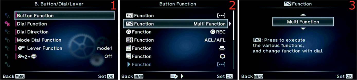
Figure 6.16D: Assigning a Button task to the Fn2 Button function
Use the following steps to assign one of the Button tasks to the Fn2 Button function:
1. Choose Button Function from the B. Button/Dial/Lever menu and scroll to the right (figure 6.16D, image 1).
2. Select Fn2 Function from the Button Function menu and scroll to the right (figure 6.16D, image 2).
3. Choose one of the available Button tasks from the up/down menu (figure 6.16D, image 3). Use the Button Tasks List in Appendix: Button Tasks Reference to decide which task you will assign to the Fn2 button.
4. Press the OK button to Set the task for the Fn2 button.
Settings Recommendation: As mentioned previously, the default task assignment for the Fn2 Function is Multi Function. I have grown accustomed to using Fn2 for selecting one of the four functions on the Multi Function list. I sometimes use the Highlight&Shadow Control for visually fine-tuning an exposure, so I leave my camera set to the default.
[Movie] Function
The [Movie] button can accept the assignment of most tasks in the Button Tasks List in Appendix: Button Tasks Reference on page 469. The default factory assignment for the [Movie] Function is REC, which you use to record movies.
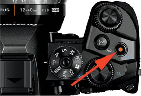
Figure 6.16E: The location of the [Movie] button
First let’s find the [Movie] button on the camera body (figure 6.16E).
Next let’s consider how to use the menus to assign one of the Button tasks to the [Movie] Button function.
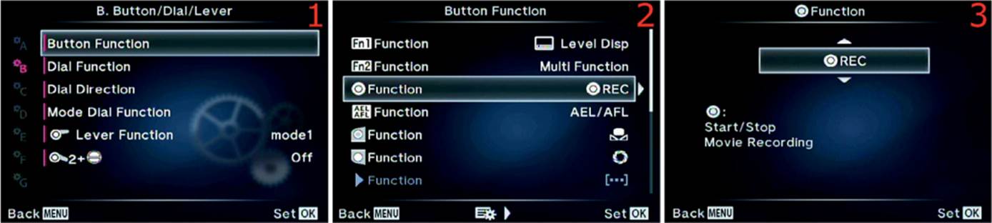
Figure 6.16F: Assigning a Button task to the [Movie] Function
Use the following steps to assign one of the Button tasks to the [Movie] Button function:
1. Choose Button Function from the B. Button/Dial/Lever menu and scroll to the right (figure 6.16F, image 1).
2. Select [Movie] Function from the Button Function menu and scroll to the right (figure 6.16F, image 2).
3. Choose one of the available Button tasks from the up/down menu (figure 6.16F, image 3). Use the Button Tasks List in Appendix: Button Tasks Reference to decide which task you will assign to the [Movie] button.
4. Press the OK button to Set the task for the [Movie] button.
Settings Recommendation: If you shoot videos with your camera, leave this button set to the factory default of REC. Otherwise you will have no way to start a movie. REC cannot be assigned to any other button. However, if you do not shoot video, you can assign most of the other Button tasks to the [Movie] button. It is conveniently located for quick access.
AEL/AFL Function
The AEL/AFL button can accept the assignment of most tasks in the Button Tasks List in Appendix: Button Tasks Reference on page 469. The default factory assignment for the AEL/AFL Function is the Button task named AEL/AFL.
First let’s find the AEL/AFL button on the camera body (figure 6.16G).
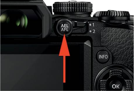
Figure 6.16G: The location of the AEL/AFL button
Next let’s consider how to use the menus to assign one of the Button tasks to the AEL/AFL Button function.
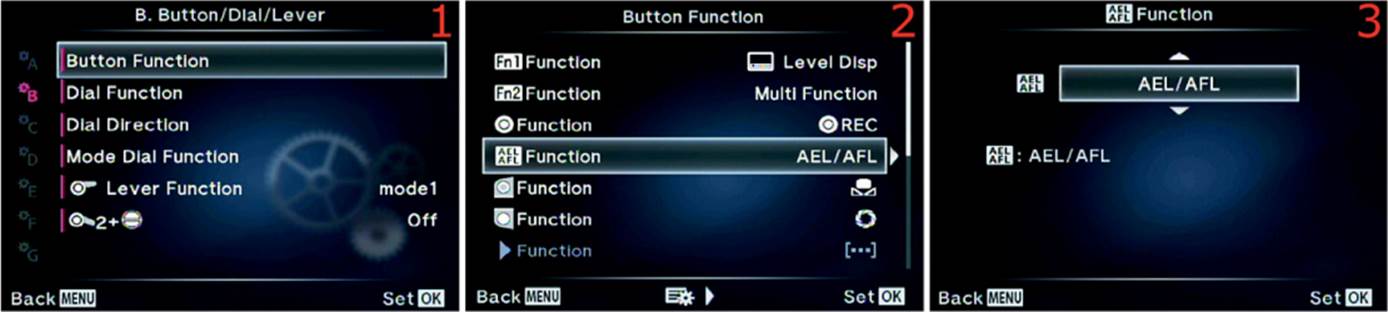
Figure 6.16H: Assigning a Button task to the AEL/AFL Button function
Use the following steps to assign one of the Button tasks to the AEL/AFL Button function:
1. Choose Button Function from the B. Button/Dial/Lever menu and scroll to the right (figure 6.16H, image 1).
2. Select AEL/AFL Function from the Button Function menu and scroll to the right (figure 6.16H, image 2).
3. Choose one of the available Button tasks from the up/down menu (figure 6.16H, image 3). Use the Button Tasks List in Appendix: Button Tasks Reference to decide which Task you will assign to the AEL/AFL button.
4. Press the OK button to Set the task for the AEL/AFL button.
Settings Recommendation: The factory default for the AEL/AFL button is AEL/AFL (autoexposure lock and autofocus lock). However, many people enjoy using this button for back-button focus. You can set up back-button focus—where autofocus is initiated by pressing the AEL/AFL button instead of the Shutter button—by using the steps in the Back-Button Focus Using the AEL/AFL Button subheading (on page 282) earlier in this chapter.
[One Touch WB] Function
The [One touch WB] button can accept the assignment of most tasks in the Button Tasks List in Appendix: Button Tasks Reference on page 469. The default factory assignment for the [One touch WB] Function is the Button task with a symbol of a flower (figure 6.16J, image 3), which represents One touch WB.
First let’s find the [One touch WB] button on the camera body (figure 6.16I).
Next let’s consider how to use the menus to assign one of the Button tasks to the [One touch WB] Button function.
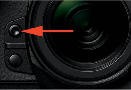
Figure 6.16I: The location of the [One touch WB] button
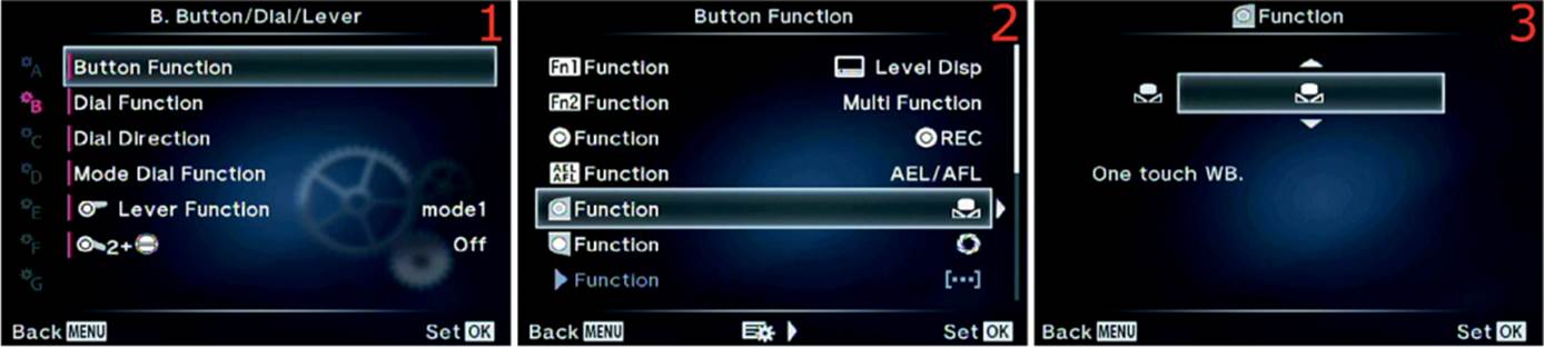
Figure 6.16J: Assigning a Button task to the [One touch WB] Button function
Use the following steps to assign one of the Button tasks to the [One touch WB] Button function:
1. Choose Button Function from the B. Button/Dial/Lever menu and scroll to the right (figure 6.16J, image 1).
2. Select [One touch WB] Function from the Button Function menu and scroll to the right (figure 6.16J, image 2).
3. Choose one of the available Button tasks from the up/down menu (figure 6.16J, image 3). Use the Button Tasks List in Appendix: Button Tasks Reference to decide which task you will assign to the [One touch WB] button.
4. Press the OK button to Set the task for the [One touch WB] button.
Settings Recommendation: If you do regular white balance readings, the [One touch WB] task makes it very simple to take a new WB reading from a white card and assign it to one of the four Capture WB memory locations on the WB menu.
On the other hand, if you usually use Auto WB and rarely take special WB readings, the [One touch WB] Button function can easily be assigned to another Button task of your choice, such as ISO, BKT (bracketing), Peaking, or Magnify (10x). Since I shoot mostly in RAW mode and seldom do specific WB readings, I often assign Magnify to the [One touch WB] button.
[Preview] Function
The [Preview] button can accept the assignment of most tasks in the Button Tasks List in Appendix: Button Tasks Reference on page 469. The default factory assignment for the [Preview] Button function is the Button task that has a symbol of the shutter blades of a lens iris (figure 6.16L, image 3), which represents depth of field (DOF) Preview.
First let’s find the [Preview] button on the camera body (figure 6.16K).
Next let’s consider how to use the menus to assign one of the Button tasks to the [Preview] Button function.

Figure 6.16K: The location of the [Preview] button
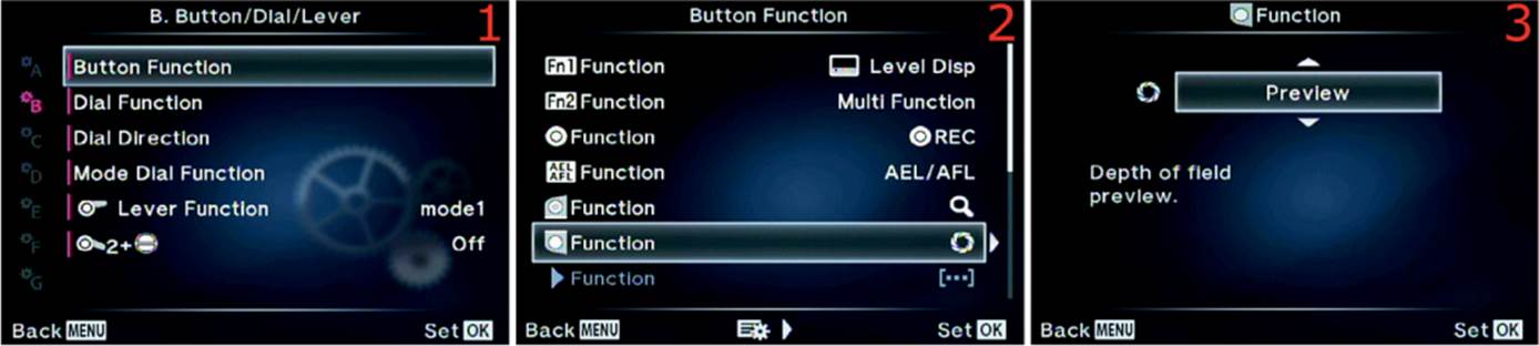
Figure 6.16L: Assigning a Button task to the [Preview] Button function
Use the following steps to assign one of the Button tasks to the [Preview] Button function:
1. Choose Button Function from the B. Button/Dial/Lever menu and scroll to the right (figure 6.16L, image 1).
2. Select [Preview] Function from the Button Function menu and scroll to the right (figure 6.16L, image 2).
3. Choose one of the available Button tasks from the up/down menu (figure 6.16L, image 3). Use the Button Tasks List in Appendix: Button Tasks Reference to decide which task you will assign to the [Preview] button.
4. Press the OK button to Set the task for the [Preview] button.
Settings Recommendation: Depth of field preview is a very important functionality. The muscle memory of many photographers is tuned to this location for a depth of field preview button because that’s where it is on most cameras. I leave my Preview button set to the Preview Task so I can determine how large the zone of sharp focus is for my subject. If you are not using depth of field preview or don’t understand depth of field, please take time to learn about it. Depth of field is critical for most types of photography.
My book Beyond Point-and-Shoot: Learning to Use a Digital SLR or Interchangeable-Lens Camera covers depth of field quite well. You can review the book here: http://www.pictureandpen.com/BeyondPS.asp.
![]() Function
Function
The right button (![]() ) on the Arrow pad (figure 6.16M) can accept only eight tasks from the Button Tasks List in Appendix: Button Tasks Reference on page 469.
) on the Arrow pad (figure 6.16M) can accept only eight tasks from the Button Tasks List in Appendix: Button Tasks Reference on page 469.
This Button function will be grayed out and unavailable unless you have the ![]()
![]()
![]()
![]() Function set to the Direct Function task. The
Function set to the Direct Function task. The ![]()
![]()
![]()
![]() Function is two items below
Function is two items below ![]() Function on the Button Function menu.
Function on the Button Function menu.
The default factory assignment for the ![]() Button function is the Button task called Flash Mode (represented by a lightning bolt symbol in figure 6.16N, image 3).
Button function is the Button task called Flash Mode (represented by a lightning bolt symbol in figure 6.16N, image 3).
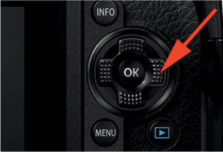
Figure 6.16M: The location of the right Arrow pad button (![]() )
)
First let’s find the right Arrow pad button (![]() ) on the camera body (figure 6.16M).
) on the camera body (figure 6.16M).
Next let’s consider how to use the menus to assign one of the Button Tasks to the ![]() Button function.
Button function.
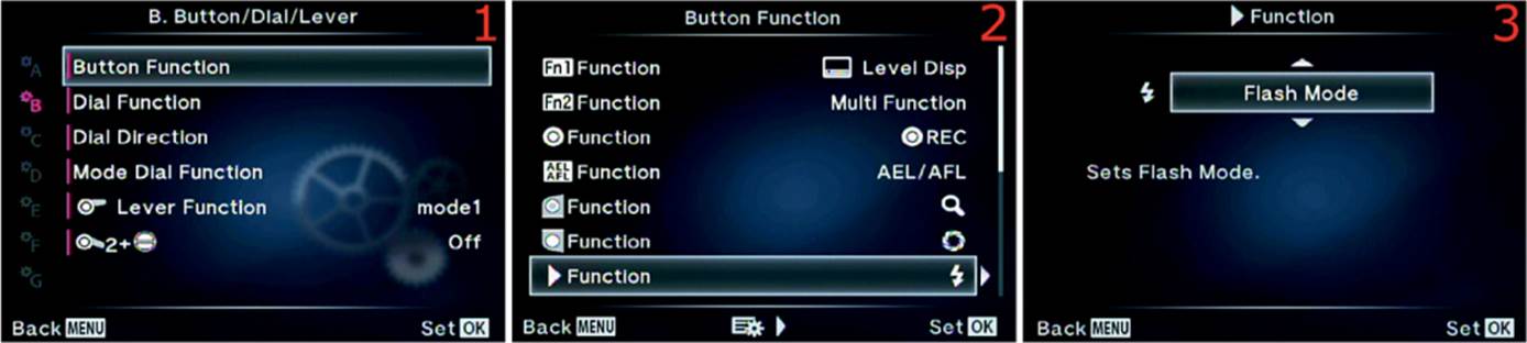
Figure 6.16N: Assigning a Button task to the ![]() Button function
Button function
Use the following steps to assign one of the Button tasks to the ![]() Button function:
Button function:
1. Choose Button Function from the B. Button/Dial/Lever menu and scroll to the right (figure 6.16N, image 1).
2. Select ![]() Function from the Button Function menu and scroll to the right (figure 6.16N, image 2).
Function from the Button Function menu and scroll to the right (figure 6.16N, image 2).
3. Choose one of the available Button tasks from the up/down menu (figure 6.16N, image 3). Use the Button Tasks List in Appendix: Button Tasks Reference to decide which task you will assign to the ![]() button.
button.
4. Press the OK button to Set the Task for the ![]() button.
button.
Settings Recommendation: I use this button to quickly access Flash Mode. This is faster than pressing the OK button when a subject is on the screen and finding the Flash Mode in the list of items. You can safely leave this function set to Flash Mode, or another mode, because it will work only when you are in shooting mode, which will not interfere with the normal use of the Arrow pad buttons, such as scrolling through pictures.
![]() Function
Function
The down Arrow pad button (![]() ) can accept only eight tasks from the Button Tasks List in Appendix: Button Tasks Reference on page 469.
) can accept only eight tasks from the Button Tasks List in Appendix: Button Tasks Reference on page 469.
This Button function will be grayed out and unavailable unless you have the ![]()
![]()
![]()
![]() Function set to the Direct Function task. The
Function set to the Direct Function task. The ![]()
![]()
![]()
![]() Function is one item below
Function is one item below ![]() Function on the Button Function menu.
Function on the Button Function menu.
The default factory assignment for the ![]() Button function is the Sequential Shooting/Self-Timer task, represented by the Sequential Shooting and Self-Timer symbols (figure 6.16P, image 3).
Button function is the Sequential Shooting/Self-Timer task, represented by the Sequential Shooting and Self-Timer symbols (figure 6.16P, image 3).
First let’s find the down Arrow pad button (![]() ) on the camera body (figure 6.16O).
) on the camera body (figure 6.16O).
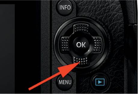
Figure 6.16O: The location of the down Arrow pad button (![]() )
)
Next let’s consider how to use the menus to assign one of the Button tasks to the ![]() Button function.
Button function.
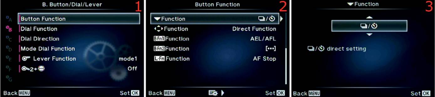
Figure 6.16P: Assigning a Button task to the ![]() Button function
Button function
Use the following steps to assign one of the Button tasks to the ![]() Button function:
Button function:
1. Choose Button Function from the B. Button/Dial/Lever menu and scroll to the right (figure 6.16P, image 1).
2. Select ![]() Function from the Button Function menu and scroll to the right (figure 6.16P, image 2).
Function from the Button Function menu and scroll to the right (figure 6.16P, image 2).
3. Choose one of the available Button tasks from the up/down menu (figure 6.16P, image 3). Use the Button Tasks List in Appendix: Button Tasks Reference to decide which task you will assign to the ![]() button.
button.
4. Press the OK button to Set the Task for the ![]() button.
button.
Settings Recommendation: I use this button to quickly access the WB (white balance) settings. The camera already has a Sequential shooting/Self-timer/HDR button (on the top left of the camera, just above the On/Off button).
You can leave this function set to whatever mode you choose because it will work only when you are in shooting mode, which will not interfere with normal use of the Arrow pad buttons, such as moving the AF Area Pointer around the 81 AF Target positions (or 37 positions if a Four Thirds lens is mounted).
![]()
![]()
![]()
![]() Function
Function
The Arrow pad’s four buttons (![]()
![]()
![]()
![]() ) can accept only one task from the Button Tasks List in Appendix: Button Tasks Reference on page 469, the [•••] AF Area Select task.
) can accept only one task from the Button Tasks List in Appendix: Button Tasks Reference on page 469, the [•••] AF Area Select task.
This assignment will cancel the task assignments of the previous two Button functions we discussed: the ![]() button and the
button and the ![]() button. When the normal factory default [•••] AF Area Select is chosen, the
button. When the normal factory default [•••] AF Area Select is chosen, the ![]() and
and ![]() Functions will be grayed out on the Button Function menu. If you want to use the
Functions will be grayed out on the Button Function menu. If you want to use the ![]() and
and ![]() buttons for one of the eight Button tasks they each support, you must set the
buttons for one of the eight Button tasks they each support, you must set the ![]()
![]()
![]()
![]() Function to Direct Function.
Function to Direct Function.
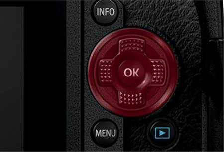
Figure 6.16Q: The location of the four Arrow pad buttons (![]()
![]()
![]()
![]() ), shown in red
), shown in red
First let’s find the Arrow pad on the camera body (figure 6.16Q).
Next let’s consider how to use the menus to configure the ![]()
![]()
![]()
![]() Function.
Function.
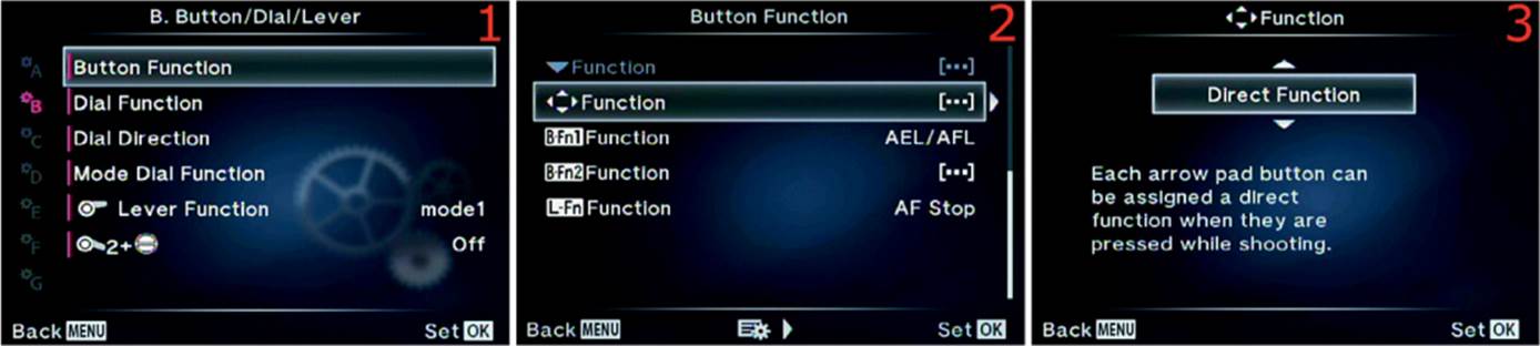
Figure 6.16R: Assigning the [•••] AF Area Select Button task to the ![]()
![]()
![]()
![]() Button function
Button function
Use the following steps to configure the ![]()
![]()
![]()
![]() Function:
Function:
1. Choose Button Function from the B. Button/Dial/Lever menu and scroll to the right (figure 6.16R, image 1).
2. Select ![]()
![]()
![]()
![]() Function from the Button Function menu and scroll to the right (figure 6.16R, image 2).
Function from the Button Function menu and scroll to the right (figure 6.16R, image 2).
3. Choose Off, [•••] AF Area Select, or Direct Function (figure 6.16R, image 3). When it is set to Off the Arrow pad will still do normal things, such as scroll through pictures and move the AF Area Pointer around, but the individual buttons offer no extra functionality. If it is set to [•••] AF Area Select, the Arrow pad displays the 81 point AF Area screen (or 37 points with Four Thirds lenses) when you press any of the four arrow buttons, so you can move the AF Area Pointer to whichever AF point you want to use for autofocus. Either of these two settings (Off or [•••] AF Area Select) disables the ![]() and
and ![]() Functions, and their menu choices become grayed out. If it is set to Direct Function, you can assign one of eight Button tasks to each of the
Functions, and their menu choices become grayed out. If it is set to Direct Function, you can assign one of eight Button tasks to each of the ![]() and
and ![]() buttons. Also, when Direct Function is active, the
buttons. Also, when Direct Function is active, the ![]() button opens ± Exposure compensation, and the
button opens ± Exposure compensation, and the ![]() button offers the 81 point (or 37 point) AF Target screen.
button offers the 81 point (or 37 point) AF Target screen.
4. Press the OK button to Set the value for the ![]()
![]()
![]()
![]() buttons.
buttons.
Settings Recommendation: If you constantly move the AF Area Pointer around the screen and carefully choose which AF point to use for autofocus, you may want to set the ![]()
![]()
![]()
![]() Function to [•••] AF Area Select. This gives you the most direct control over which AF point is in use when you press any of the Arrow pad buttons to open the AF screen with 81 (or 37) points.
Function to [•••] AF Area Select. This gives you the most direct control over which AF point is in use when you press any of the Arrow pad buttons to open the AF screen with 81 (or 37) points.
If you do not use AF points very often, you may want to set the ![]()
![]()
![]()
![]() Function to Direct Function and then experiment with the seven Tasks you can assign to each of the right and down Arrow pad keys.
Function to Direct Function and then experiment with the seven Tasks you can assign to each of the right and down Arrow pad keys.
B-Fn1 Function
The B-Fn1 button is found on the optional HLD-7 battery holder. You can use this function only if you have an HLD-7 mounted on your camera. The B-Fn1 button can accept the assignment of most tasks in the Button Tasks List in Appendix: Button Tasks Reference on page 469. The default factory assignment for the B-Fn1 Button function is the Button task named AEL/AFL.
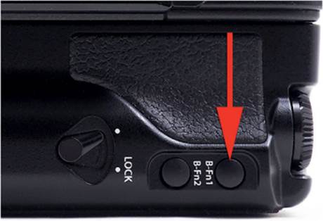
Figure 6.16S: The location of the B-Fn1 button on the HLD-7 battery holder
First let’s find the B-Fn1 button on the HLD-7 battery holder (figure 6.16S).
Next let’s consider how to use the menus to assign one of the Button tasks to the B-Fn1 Button function.
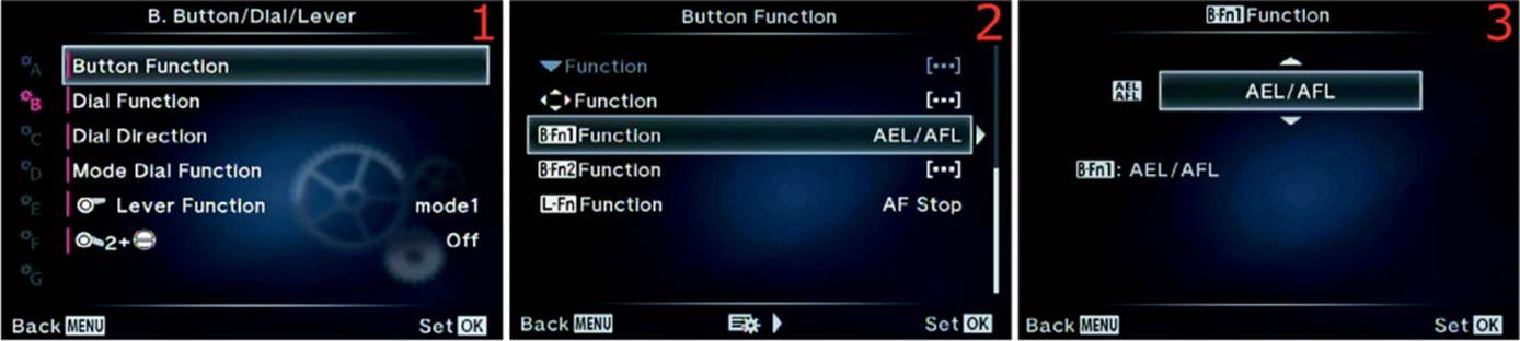
Figure 6.16T: Assigning a Button task to the B-Fn1 Button function
Use the following steps to assign one of the Button tasks to the B-Fn1 Button function:
1. Choose Button Function from the B. Button/Dial/Lever menu and scroll to the right (figure 6.16T, image 1).
2. Select B-Fn1 Function from the Button Function menu and scroll to the right (figure 6.16T, image 2).
3. Choose one of the available Button tasks from the up/down menu (figure 6.16T, image 3). Use the Button Tasks List in Appendix: Button Tasks Reference to decide which task you will assign to the B-Fn1 button.
4. Press the OK button to Set the task for the B-Fn1 button.
Settings Recommendation: I assigned ISO to the B-Fn1 Button function. I change the ISO quite a lot, and I like it to be both on the camera body’s Fn1 button and on the HLD-7’s B-Fn1 button. Of course, there are so many Tasks you can assign to the HLD-7 that this extra button adds functionality to the camera. The cost of an HLD-7 is very reasonable, and it adds a bigger grip and more mass for sharper handheld images.
B-Fn2 Function
The B-Fn2 button is found only on the optional HLD-7 battery holder. You can use this function only if you have an HLD-7 mounted on your camera. The B-Fn2 button can accept the assignment of most tasks in the Button Tasks List in Appendix: Button Tasks Reference on page 469. The default factory assignment for the B-Fn2 Button function is the Button task named [•••] AF Area Select.
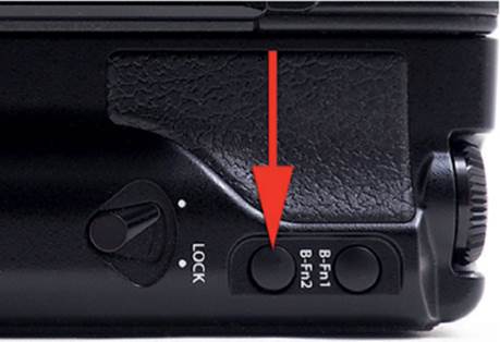
Figure 6.16U: The location of the B-Fn2 button on the HLD-7 battery holder
First let’s find the B-Fn2 button on the HLD-7 power battery holder (figure 6.16U).
Next let’s consider how to use the menus to assign one of the Button tasks to the B-Fn2 Button function.
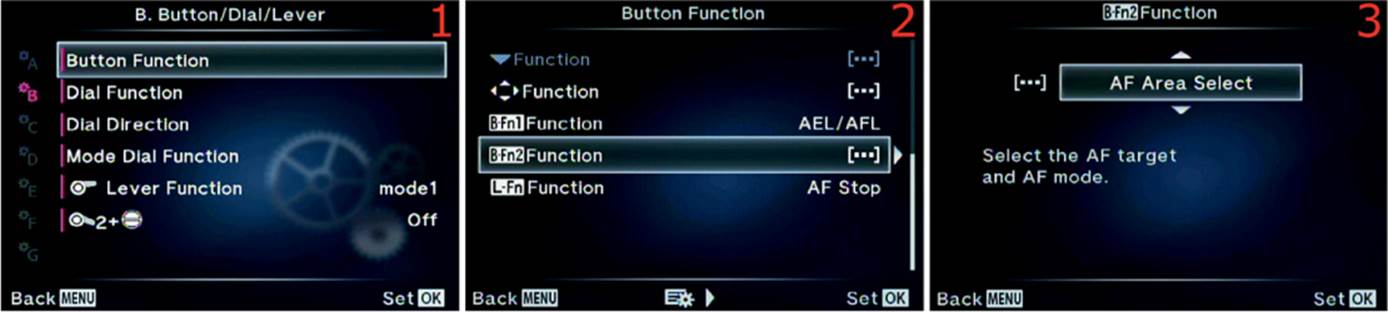
Figure 6.16V: Assigning a Button task to the B-Fn2 Button function
Use the following steps to assign one of the Button tasks to the B-Fn2 Button function:
1. Choose Button Function from the B. Button/Dial/Lever menu and scroll to the right (figure 6.16V, image 1).
2. Select B-Fn2 Function from the Button Function menu and scroll to the right (figure 6.16V, image 2).
3. Choose one of the available Button tasks from the up/down menu (figure 6.16V, image 3). Use the Button Tasks List in Appendix: Button Tasks Reference to decide which task you will assign to the B-Fn2 button.
4. Press the OK button to Set the Task for the B-Fn2 button.
Settings Recommendation: I assigned the Preview task to the B-Fn2 button. When I rotate the camera for a vertical shot with the HLD-7’s Shutter button, I often want to check the depth of field. However, since the camera is rotated my finger will not reach the normal Preview button, so I use the B-Fn2 button instead.
L-Fn Function
The L-Fn button is found only on certain lenses. For instance, the professional M.Zuiko 12–40mm f/2.8 ED lens has one. You can use this Button function only if the lens mounted on your camera has the L-Fn button. The L-Fn button can accept the assignment of most tasks in the Button Tasks List in Appendix: Button Tasks Reference on page 469. The default factory assignment for the L-Fn Button function is the Button task named AF Stop, which cannot be assigned to any of the buttons on the camera body.
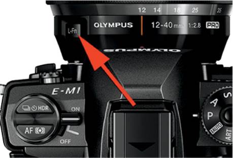
Figure 6.16W: The location of the L-Fn button on an M.Zuiko 12–40mm f/2.8 ED PRO lens
First let’s find the L-Fn button on the lens (figure 6.16W).
Next let’s consider how to use the menus to assign one of the Button tasks to the L-Fn Button function.
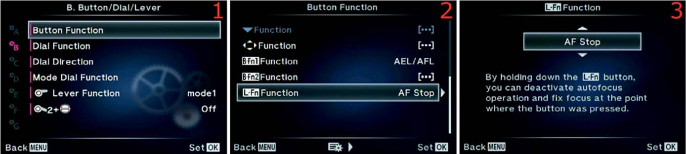
Figure 6.16X: Assigning a Button task to the L-Fn Button function
Use the following steps to assign one of the Button tasks to the L-Fn Button function:
1. Choose Button Function from the B. Button/Dial/Lever menu and scroll to the right (figure 6.16X, image 1).
2. Select L-Fn Function from the Button Function menu and scroll to the right (figure 6.16X, image 2).
3. Choose one of the available Button tasks from the up/down menu (figure 6.16X, image 3). Use the Button Tasks List in Appendix: Button Tasks Reference to decide which task you will assign to the L-Fn button.
4. Press the OK button to Set the task for the L-Fn button.
Settings Recommendation: I set the L-Fn button on my lens to [•••] AF Area Select because I often have the factory default button for [•••] AF Area Select (Fn1) assigned to ISO instead. It makes a lot of sense to have the [•••] AF Area Select function assigned to a button on the lens since the lens provides focus.
Dial Function
The E-M1 has two dials on top of the camera: Front Dial and Rear Dial (figure 6.17A). These two dials are used to control various camera functions; like the camera buttons, they can be configured to do something different than the factory default settings.
The Front and Rear Dials have a relationship with the Mode Dial, in that you can change what the Front and Rear Dials accomplish when you use the different modes (P, S, A, M) on the Mode Dial.
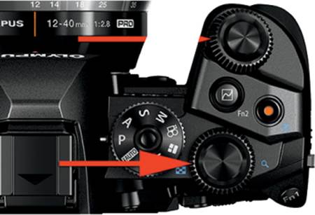
Figure 6.17A: Front and Rear Dials
Additionally, the two dials have special functionalities when you use the camera menus or look at pictures on the monitor.
Let’s examine each of the functions that can be assigned to the Front and Rear Dials.
P Mode Functions
When you set the Mode Dial to P (Program) mode, the Front and Rear Dials offer the eight function combinations shown in table 6.1.
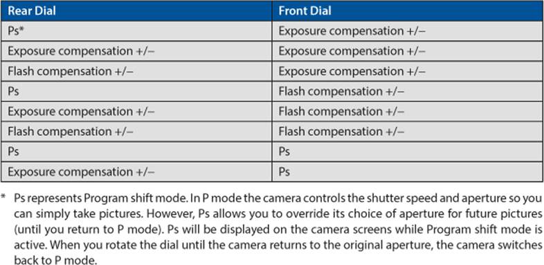
Table 6.1: P mode Front and Rear Dial function combinations
Now let’s examine the screens and steps to choose one of the function combinations shown in table 6.1.

Figure 6.17B: Configuring the Front and Rear Dials for P mode
1. Select Dial Function from the B. Button/Dial/Lever menu and scroll to the right (figure 6.17B, image 1).
2. A small window will open with the following choices: P, A, S, M, Menu, and ![]() . Choose P (Program mode) and scroll to the right (figure 6.17B, image 2).
. Choose P (Program mode) and scroll to the right (figure 6.17B, image 2).
3. You will see a graphical representation of the two dials and their current function assignments (figure 6.17B, image 3). The camera defaults to Ps for the Rear Dial and Exposure compensation (+/–) for the Front Dial. There is a small up/down menu. Press up or down to choose different combinations of functions for the two dials. Table 6.1 lists the sequential combinations for pressing down on the Arrow pad.
4. When you have chosen your favorite dial function combination for P mode, press the OK button to Set the combination.
Settings Recommendation: I leave my camera set to the factory default of Ps/Exposure compensation +/– because I often override the aperture setting when I use P mode.
A Mode Functions
When you set the Mode Dial to A (Aperture-priority) mode, the Front and Rear Dials offer the five function combinations shown in table 6.2.
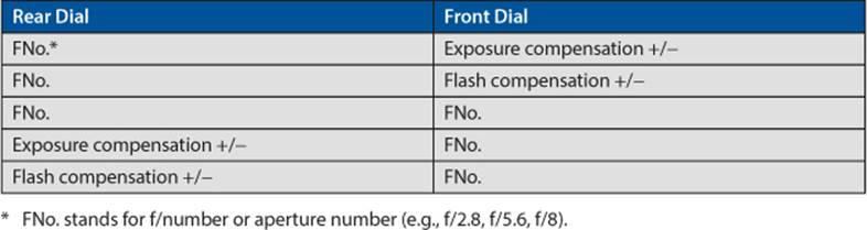
Table 6.2: A mode Front and Rear Dial function combinations
Now let’s examine the screens and steps to choose one of the function combinations shown in table 6.2.

Figure 6.17C: Configuring the Front and Rear Dials for A mode
1. Select Dial Function from the B. Button/Dial/Lever menu and scroll to the right (figure 6.17C, image 1).
2. A small window will open with the following choices: P, A, S, M, Menu, and ![]() . Choose A (Aperture-priority) mode and scroll to the right (figure 6.17C, image 2).
. Choose A (Aperture-priority) mode and scroll to the right (figure 6.17C, image 2).
3. You will see a graphical representation of the two dials and their current function assignments (figure 6.17C, image 3). The camera defaults to FNo. for the Rear Dial and Exposure compensation (+/–) for the Front Dial. There is a small up/down menu. Press up or down to choose different combinations of functions for the two dials. Table 6.2 lists the sequential combinations for pressing down on the Arrow pad.
4. When you have chosen your favorite dial function combination for A mode, press the OK button to Set the combination.
Settings Recommendation: I leave my camera set to the factory default of FNo./Exposure compensation +/– because it seems reasonable to have the aperture adjusted by the Rear Dial in Aperture-priority mode. However, if you are used to another camera brand, you may be accustomed to having the Front Dial adjust the aperture. Use whichever combination seems most natural to you.
S Mode Functions
When you set the Mode Dial to S (Shutter-priority) mode, the Front and Rear Dials offer the five function combinations shown in table 6.3.
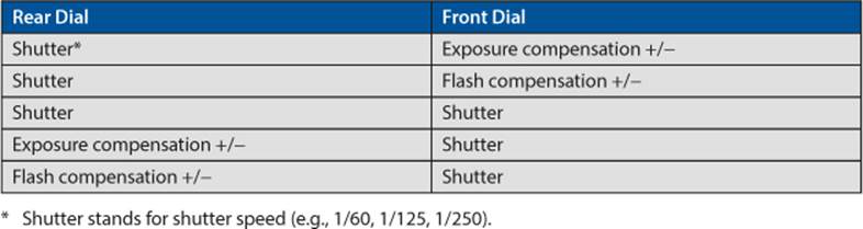
Table 6.3: S mode Front and Rear Dial function combinations
Now let’s examine the screens and steps to choose one of the function combinations shown in table 6.3.
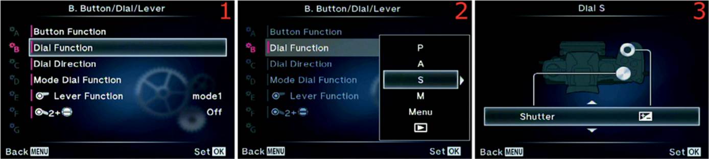
Figure 6.17D: Configuring the Front and Rear Dials for S mode
1. Select Dial Function from the B. Button/Dial/Lever menu and scroll to the right (figure 6.17D, image 1).
2. A small window will open with the following choices: P, A, S, M, Menu, and ![]() . Choose S (Shutter-priority) mode and scroll to the right (figure 6.17D, image 2).
. Choose S (Shutter-priority) mode and scroll to the right (figure 6.17D, image 2).
3. You will see a graphical representation of the two dials and their current function assignments (figure 6.17D, image 3). The camera defaults to Shutter for the Rear Dial and Exposure compensation (+/–) for the Front Dial. There is a small up/down menu. Press up or down to choose different combinations of functions for the two dials. Table 6.3 lists the sequential combinations for pressing down on the Arrow pad.
4. When you have chosen your favorite dial function combination for S mode, press the OK button to Set the combination.
Settings Recommendation: I leave my camera set to the factory default of Shutter/Exposure compensation +/– because every camera I’ve used has the rear dial set to adjust the shutter speed in Shutter-priority mode. I don’t want to make myself fight muscle memory when I take important pictures!
M Mode Functions
When you set the Mode Dial to M (Manual) mode, the Front and Rear Dials offer the two function combinations shown in table 6.4.
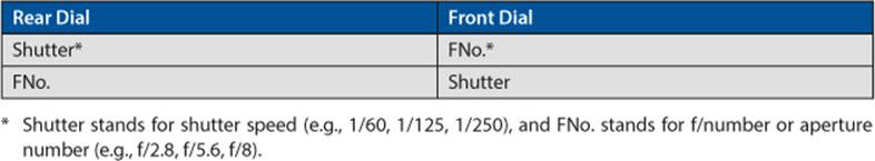
Table 6.4: M mode Front and Rear Dial function combinations
Now let’s examine the screens and steps to choose one of the function combinations shown in table 6.4.
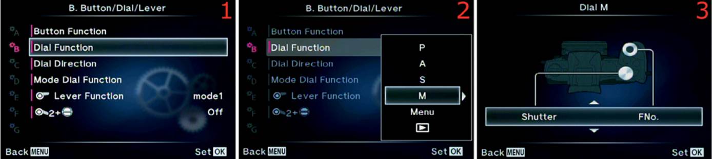
Figure 6.17E: Configuring the Front and Rear Dials for M mode
1. Select Dial Function from the B. Button/Dial/Lever menu and scroll to the right (figure 6.17E, image 1).
2. A small window will open with the following choices: P, A, S, M, Menu, and ![]() . Choose M (Manual) mode and scroll to the right (figure 6.17E, image 2).
. Choose M (Manual) mode and scroll to the right (figure 6.17E, image 2).
3. You will see a graphical representation of the two dials and their current function assignments (figure 6.17E, image 3). The camera defaults to Shutter for the Rear Dial and FNo. for the Front Dial. There is a small up/down menu. Press up or down to choose different combinations of functions for the two dials. Table 6.4 lists the sequential combinations for pressing down on the Arrow pad.
4. When you have chosen your favorite dial function combination for M mode, press the OK button to Set the combination.
Settings Recommendation: I leave my camera set to the factory default of Shutter/FNo. because I’m accustomed to that combination. You may prefer a different combination.
Menu Functions
When you use the camera menus to make setting adjustments or when you simply navigate the Menu system, the Front and Rear Dials offer the two combinations shown in table 6.5.

Table 6.5: Menu system navigation Front and Rear Dial function combinations
The arrows in table 6.5 indicate scrolling directions. The factory default is for the ![]() and
and ![]() Arrow pad keys to scroll up and down, and the
Arrow pad keys to scroll up and down, and the ![]() and
and ![]() keys to move left or right within the selected Value.
keys to move left or right within the selected Value.
Now let’s examine the screens and steps to choose one of the function combinations shown in table 6.5.
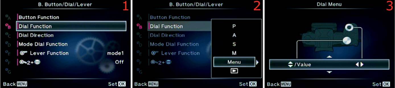
Figure 6.17F: Configuring the Front and Rear Dials for moving around in the Menu system
1. Select Dial Function from the B. Button/Dial/Lever menu and scroll to the right (figure 6.17F, image 1).
2. A small window will open with the following choices: P, A, S, M, Menu, and ![]() . Choose Menu and scroll to the right (figure 6.17F, image 2).
. Choose Menu and scroll to the right (figure 6.17F, image 2).
3. You will see a graphical representation of the two dials and their current function assignments (figure 6.17F, image 3). The camera defaults to ![]()
![]() /Value for the Rear Dial and
/Value for the Rear Dial and ![]()
![]() for the Front Dial. There is a small up/down menu. Press up or down to choose different combinations of functions for the two dials. Table 6.5 lists the sequential combinations for pressing down on the Arrow pad.
for the Front Dial. There is a small up/down menu. Press up or down to choose different combinations of functions for the two dials. Table 6.5 lists the sequential combinations for pressing down on the Arrow pad.
4. When you have chosen your favorite dial function combination for the Menu system, press the OK button to Set the combination.
Settings Recommendation: I leave my camera set to the factory default for using the dials within the Menu system. It seems most natural to me to scroll up and down with the Rear Dial and left and right with the Front Dial. If you prefer the other direction, simply make the change.
Image Viewing Functions
When you review images on the camera monitor, the Front and Rear Dials offer the two function combinations shown in table 6.6.
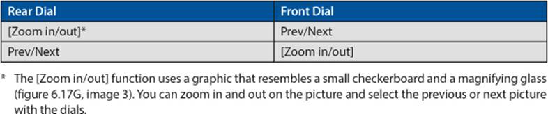
Table 6.6: Image review Front and Rear Dial function combinations
Now let’s examine the screens and steps to choose one of the function combinations shown in table 6.6.
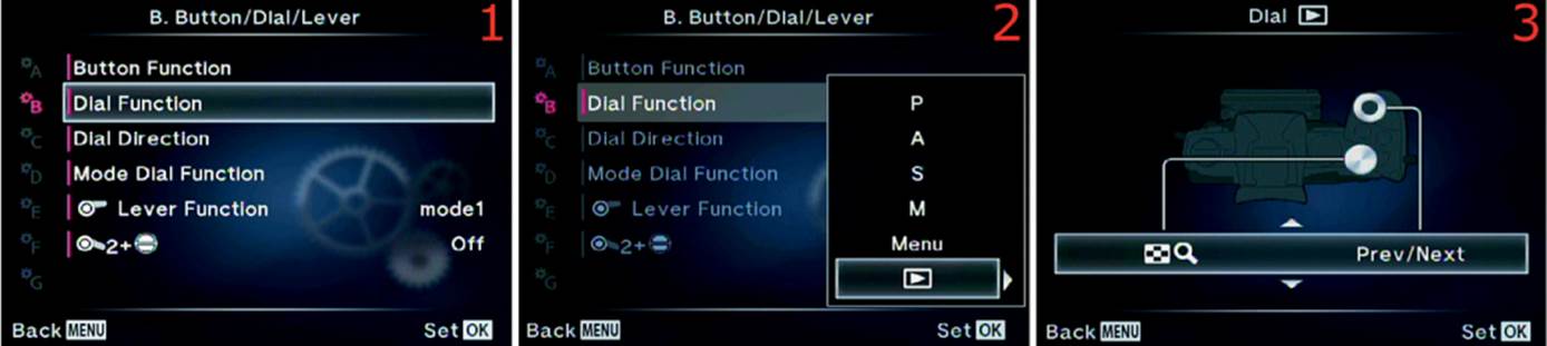
Figure 6.17G: Configuring the Front and Rear Dials for Image review navigation (![]() )
)
1. Select Dial Function from the B. Button/Dial/Lever menu and scroll to the right (figure 6.17G, image 1).
2. A small window will open with the following choices: P, A, S, M, Menu, and ![]() . Choose
. Choose ![]() and scroll to the right (figure 6.17G, image 2).
and scroll to the right (figure 6.17G, image 2).
3. You will see a graphical representation of the two dials and their current function assignments (figure 6.17G, image 3). The camera defaults to [Zoom in/out] for the Rear Dial and Prev/Next for the Front Dial. There is a small up/down menu. Press up or down to choose different combinations of functions for the two dials. Table 6.6 lists the sequential combinations for pressing down on the Arrow pad.
4. When you have chosen your favorite dial function combination for Image review navigation (![]() ), press the OK button to Set the combination.
), press the OK button to Set the combination.
Settings Recommendation: I leave my camera set to the factory default of [Zoom in/out] on the Rear Dial and Prev/Next on the Front Dial. If you like the reverse order, you can change it.
Dial Direction
Use Dial Direction to reverse the direction you turn a dial to open and close the aperture (A mode) or raise and lower the shutter speed (S mode). In other words, you can control the direction you turn the dial—clockwise or counterclockwise—to change the aperture or shutter speed.
Dial Direction also allows you to configure Program shift (Ps) mode so the direction you turn the dial either follows or turns in the opposite direction of the current A mode dial direction or S mode dial direction.
Let’s examine how the Dial Direction modes are selected.
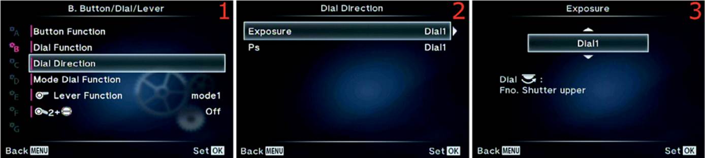
Figure 6.18A: Changing the Dial Direction for the Exposure modes
To change the direction you turn the dial for exposure operations, use the following steps:
1. Select Dial Direction from the B. Button/Dial/Lever menu and scroll to the right (figure 6.18A, image 1).
2. Choose the Exposure setting from the Dial Direction menu and scroll to the right (figure 6.18A, image 2).
3. Select Dial 1 from the Exposure up/down menu to leave the dial rotation direction that raises the f/number or aperture set to the factory default, or select Dial 2 to reverse the normal rotation direction (figure 6.18A, image 3).
4. Press the OK button to Set the dial rotation direction.
Next you should consider if you want the direction you turn the dial in Ps mode to match the direction you turn the dial to change the shutter speed or aperture, or if you want it to turn in the opposite direction. Let’s see how.

Figure 6.18B: Changing the Dial Direction for Program shift (Ps) mode
To change the direction you turn the dial for Ps mode operations, use the following steps:
1. Select Dial Direction from the B. Button/Dial/Lever menu and scroll to the right (figure 6.18B, image 1).
2. Choose Ps from the Dial Direction menu and scroll to the right (figure 6.18B, image 2).
3. Select Dial 1 from the up/down menu to cause the dial rotation to match the direction used when you have the camera set to Shutter-priority (S) mode (figure 6.18B, image 3). Select Dial 2 to cause the dial rotation to match the direction used when you have the camera set to Aperture-priority (A) mode.
4. Press the OK button to Set the Ps mode’s dial rotation direction.
Settings Recommendation: In addition to choosing which dial you use to change the shutter speed and aperture, you can use the Dial Direction setting to change the direction you rotate the dials to make exposure adjustments. This is nice for people who are accustomed to turning different dials or turning dials in a different direction.
Mode Dial Function
If do not regularly use some of the settings on the Mode Dial (e.g., P, A, S, M, ART, SCN), you can reconfigure four of them for different purposes. You can assign up to four Myset locations to one of the Mode Dial choices. If the Mode Dial function is grayed out, it means you have not saved your camera configuration to one of the Myset memory locations in Shooting Menu 1.
Recall that a Myset location allows you to store camera settings. You can configure the camera in different ways and store the settings for later recall. The camera has four Myset locations (Myset1 to Myset4), as discussed in the chapter Shooting Menu 1 under the subheadingReset/Myset on page 132. Refer to that chapter for more information.
Let’s examine how to assign a Myset location to the SCN (Scene Modes) position on the Mode Dial. You can assign one of the Myset locations to any position on the dial. We will use the SCN mode position as an example; however, you can assign any of the four Myset memory locations to any of the nine Mode Dial positions. After you make an assignment and select the assigned Mode Dial position, the settings in the Myset location are immediately loaded into the camera’s active memory.
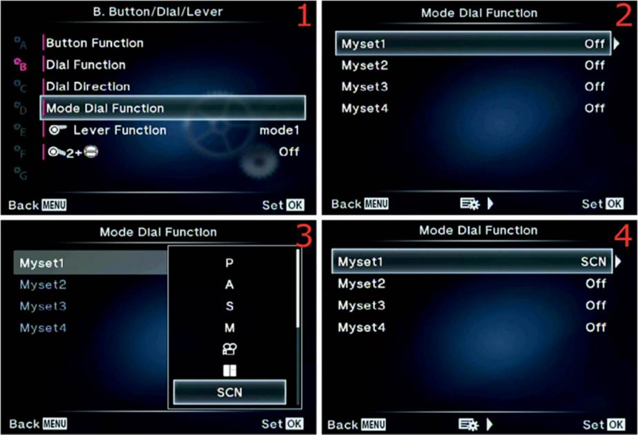
Figure 6.19: Assigning a Myset location to one of the Mode Dial positions
Use the following steps to assign a Myset location to a position on the Mode Dial:
1. Choose Mode Dial Function from the B. Button/Dial/Lever menu and scroll to the right (figure 6.19, image 1).
2. Select the Myset memory location to which you want to assign a Mode Dial position and scroll to the right (figure 6.19, image 2). I selected Myset1.
3. A small window will open and display the nine Mode Dial positions (figure 6.19, image 3). Select the one you want to use. The Myset memory location will be assigned to the selected Mode Dial position and replace the normal functionality of that Mode Dial position. I chose SCN mode.
4. Press the OK button to Set the new function for that Mode Dial position. Repeat steps 2 and 3 for any other Myset locations you want to save to any other Mode Dial positions.
5. The camera will now display SCN (or whichever Mode Dial position you chose to use) next to the Myset number you assigned (figure 6.19, image 4). Whenever I rotate the Mode Dial to SCN, the camera will immediately load the settings stored in the Myset1 memory location.
Note: If you undo this assignment by setting the Myset location in figure 6.19, image 4, to Off, the normal Mode Dial functionality will return.
Settings Recommendation: If you want to customize the Mode Dial, this is a convenient function. Many other camera brands offer similar functions that allow you to load special camera configurations. Not to be outdone, Olympus allows users to assign four Myset camera configurations into four Mode Dial positions.
Lever Function
Use the Lever Function to quickly change how the Dials, Movie button, Fn2 button, and autofocus work according to the current Exposure mode (P, A, S, M). First let’s locate the Lever on the camera body and then see how to use it.
In figure 6.20A you can see that the lever has numbered upper (1) and lower (2) positions. Moving the lever between those two positions changes the basic camera functionality for a limited number of controls and settings. To make it simple, let’s look at table 6.7, which shows the Lever Function positions and how they affect the Front and Rear Dials, the Movie and Fn2 buttons, and Autofocus.
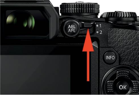
Figure 6.20A: The Lever on the back of the E-M1

Table 6.7: Lever Function modes
Now let’s examine how to choose one of the five modes for the Lever Function.
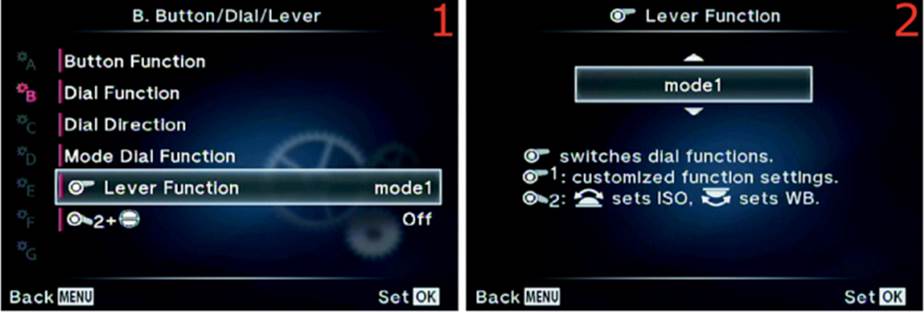
Figure 6.20B: Changing modes for the Lever Function
Use the following steps to assign a mode to the Lever Function:
1. Choose Lever Function from the B. Button/Dial/Lever menu and scroll to the right (figure 6.20B, image 1).
2. From the up/down menu, choose one of the four Lever Function modes (mode1 through mode4) or Off (figure 6.20B, image 2). Refer to table 6.7 for what each mode does.
3. Press the OK button to Set the mode for the Lever Function.
Settings Recommendation: I like to use Lever Function mode1 so I will have a quick way to get to the ISO and White balance settings without tying up any of the camera’s assignable buttons. Read table 6.7 carefully and see if you prefer another use for the Lever Function.
Lever Position 2 and the AF/HDR Button
When you press the Sequential shooting/Self-timer/HDR side of the AF/HDR button (figure 6.21A, upper arrow), you will see a screen to adjust the Sequential shooting/Self-timer and HDR settings. When you press the AF/Metering side of the AF/HDR button (figure 6.21A, lower arrow) you will see a screen to adjust Autofocus and Metering.
If you set this function to On, the AF/HDR button will change its functionality when you select Lever position 2 (down), and it will use the normal functionality when the Lever is at position 1 (up).
Table 6.8 lists the differences in button functionality when this function is set to On and the Lever is moved between the two positions. If this function is Off, the Lever will not affect the functionality of the AF/HDR button.
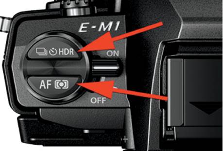
Figure 6.21A: AF/HDR button
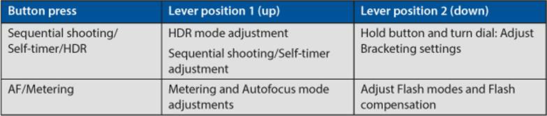
Table 6.8: AF/HDR buttons and Lever position relationships
Let’s see how to enable or disable the Lever Position 2 and AF/HDR button.
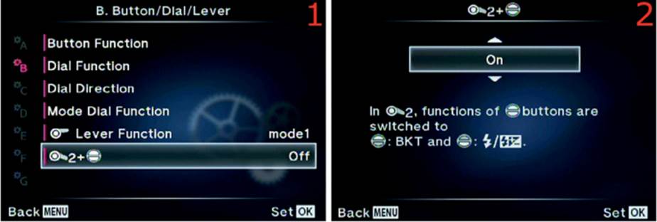
Figure 6.21B: Changing modes for the Lever Function
Use the following steps to change the functionality of the AF/HDR button when the Lever is moved from position 1 to position 2:
1. Choose the symbol that represents the Lever in position 2 and the AF/HDR button from the B. Button/Dial/Lever menu and scroll to the right (figure 6.21B, image 1).
2. From the up/down menu, choose either On or Off (figure 6.20B, image 2). Refer to table 6.8 to see how the AF/HDR and Lever position relationship changes when On is selected.
3. Press the OK button to Set the mode.
Settings Recommendation: I leave this function set to On because it gives me a faster way to enable and use Bracketing and Flash mode adjustments. Having this function set to On does not interfere with the settings of the five Lever modes that we discussed in the previous Lever Functionsubsection.
Custom Menu C. Release/[FPS]
The C. Release/[FPS] (frames per second) menu has an internal selection of eight functions that affect how the camera releases the shutter to take a picture.
First let’s examine how to open the Release/[FPS] functions on the Custom Menu screen, then we will consider how the individual Release/[FPS] functions work.
Figure 6.22 displays the C. Release/[FPS] selection on the Custom Menu. All functions listed in this section are under this menu selection. To access them, choose the C. Release/[FPS] menu and press the OK button, or scroll to the right with the Arrow pad.
Let’s examine each of the eight C. Release/[FPS] functions.

Figure 6.22: The opening menu selection for the C. Release/[FPS] functions
Rls Priority S
The Rls (release) Priority function tells the camera whether it is more important to release the shutter at all costs or to wait until autofocus has focused on the subject before allowing the shutter to release.
This is a major consideration for most types of photography. Who wants out-of-focus images? Rls Priority S is concerned with how release priority works when the camera is set to AF-S (single AF) release mode.
When you shoot one frame at a time, there is usually sufficient time to make sure the subject is in focus before you release the shutter. Therefore, for most types of single AF shooting (autofocus locks on the subject and does not automatically update) the best choice is to set Rls Priority S to Off (factory default).

Figure 6.23: Setting release priority for single AF (AF-S) shooting
Use the following steps to enable or disable Rls Priority S:
1. Choose Rls Priority S from the C. Release/[FPS] menu and scroll to the right (figure 6.23, image 1).
2. A small window will open with the choices of Off and On (figure 6.23, image 2). Choose Off if you want the camera to release the shutter only if something is in focus (hopefully the subject). Set it to On if you want the camera to release the shutter even if nothing is in focus.
3. Press the OK button to Set your choice.
Settings Recommendation: I am a nature shooter and usually have time to make sure the subject is in focus. I don’t want the shutter to release unless the subject (or at least something) is in focus. Most photographers do not shoot moving subjects, action, or sports in AF-S release mode. Instead, they use AF-C for continuous AF. Therefore, for most of us, setting this function to On is the best choice.
Rls Priority C
When you are shooting in AF-C (continuous AF) mode, the camera never truly locks focus on the subject. It continually seeks the best focus, and you will notice the lens refocusing as the camera and subject move. Rls Priority C is concerned with how the camera releases the shutter in AF-C mode.
If you are photographing a car race, where the cars are passing parallel directly in front of you, your images are often fine with just an initial autofocus operation because the car, although it is moving very fast, does not change distance from you, which allows the depth of field to cover minor focus variations. The focus does not have to be updated often. You can get many shots of the car as it moves parallel to you. For this type of shooting, the camera could be set to release the shutter without concern about AF (Rls Priority C set to On). Shutter release has priority! There may be a few out-of-focus frames, but the majority of images will be in good focus as the camera tries to maintain AF on the subject.
On the other hand, if you are photographing a marathon and the participants are running toward you, autofocus is critical. In this situation it is probably best to set Rls Priority C to Off so the camera will not release the shutter unless the subject is in focus.
This is a highly subjective decision that is based on what type of photography you do. Simply ask yourself if AF is more important than immediate shutter release for your style of shooting.
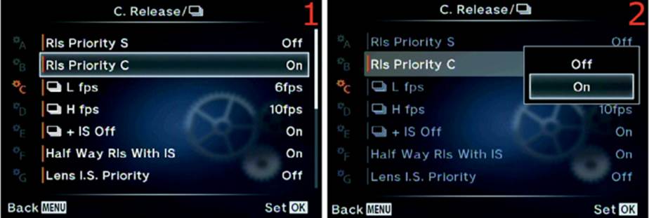
Figure 6.24: Setting release priority for continuous AF (AF-C) shooting
Use the following steps to enable or disable Rls Priority C:
1. Choose Rls Priority C from the C. Release/[FPS] menu and scroll to the right (figure 6.24, image 1).
2. A small window will open with the choices of Off and On (figure 6.24, image 2). Choose Off if you want the camera to release the shutter only if something is in focus (hopefully the subject), or set it to On if you want the camera to release the shutter even if nothing is in focus.
3. Press the OK button to Set your choice.
Settings Recommendation: Being a nature photographer biases me toward making sure the subject is in focus for every shot. I don’t often have to suffer the frustration of the subject moving at high rates of speed (other than some wildlife).
Again, whether releasing the shutter or obtaining the best focus has a higher priority is a subjective decision. For most photographers Rls Priority C should be set to Off because who wants a series of out-of-focus images mixed with in-focus images?
On the other hand, if you have a good understanding of depth of field and know how to use it to cover minor focus variations, releasing the shutter and getting the shot may be a bigger priority than how the camera focuses.
Experiment with Rls Priority C when you are using AF-C mode. If the camera performs well enough in AF-C to keep the subject in reasonable focus, you may want the shutter release to have priority over autofocus.
[Sequential] L fps
The E-M1 can shoot in [Sequential] L fps and [Sequential] H fps modes, for low and high frames-per-second rates. These modes set the approximate frames per second (fps) rate that the camera uses to take pictures in fast bursts.
[Sequential] L fps can be set from 1 fps to 6.5 fps with firmware 2.0 or 9 fps with firmware 3.0, and the camera can fully autofocus between each frame. Let’s examine how to change the rate.
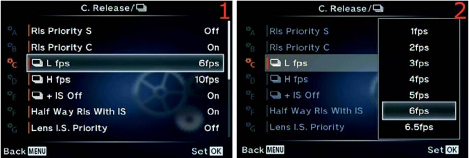
Figure 6.25: Setting a [Sequential] L fps rate
Use these steps to configure the frame rate of [Sequential] L fps:
1. Choose [Sequential] L fps from the C. Release/[FPS] menu and scroll to the right (figure 6.25, image 1).
2. A small window will open and offer you the choice of 1 frame per second (1fps) to 6.5 frames per second (6.5fps). The factory default is 6fps. With firmware 3.0, the maximum was increased to 9 fps (9fps). Choose how many fps you would like your camera to take in [Sequential] L fpsmode (figure 6.25, image 2).
3. Press the OK button to Set the frame rate.
Settings Recommendation: I usually leave my camera set to [Sequential] L mode because I want the fastest frame rate I can get that still offers full autofocus. [Sequential L] fps autofocuses on each frame, whereas [Sequential] H fps autofocuses only on the first frame in the series.
For tracking a subject that is moving erratically, [Sequential] L fps is often the best choice. You have to decide how many frames you want to deal with. If you think 6.5 fps (firmware 2.0) or 9 fps (firmware 3.0) will make too many images, you can adjust the frame rate to as low as 1 fps. Most people select the maximum frame rate and never look back!
[Sequential] H fps
[Sequential H] fps makes the camera shoot at its maximum frame rate, 10 fps, unless you decide to throttle it back to between 5 fps and 10 fps.
Unfortunately the camera cannot autofocus between frames when you are using [Sequential] H fps. It autofocuses on the first picture in the series and takes the rest of the pictures without focusing.
If you must have autofocus for each frame in the series of pictures, use [Sequential] L fps instead. That mode was discussed under the previous subheading, [Sequential] L fps.
Let’s see how to adjust the frame rate for [Sequential] H fps.
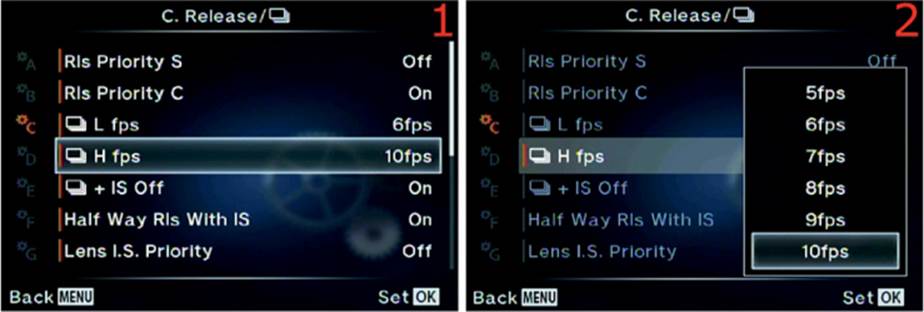
Figure 6.26: Setting a [Sequential] H fps rate
Use these steps to configure the frame rate for [Sequential] H fps:
1. Choose [Sequential] H fps from the C. Release/[FPS] menu and scroll to the right (figure 6.26, image 1).
2. A small window will open and offer you choices from 5 frames per second (5fps) to 10 frames per second (10fps). The factory default is 10fps. Choose how many fps you would like your camera to take in [Sequential] H fps mode (figure 6.26, image 2).
3. Press the OK button to Set the frame rate.
Settings Recommendation: I usually use [Sequential] L fps mode so I can take advantage of the fast frame rate and have autofocus too. When I am trying to impress my friends, though, I switch to [Sequential] H fps and fire off 20 or 30 frames.
On the other hand, if I really need extra speed, I switch to [Sequential] H fps and use the depth of field to cover the focus on subjects that are not moving toward or away from me.
Whether you use [Sequential] L or [Sequential] H fps depends on the type of subject you photograph. If you have a need for speed, 10 fps are at your command.
[Sequential] + IS Off
The 5-axis image stabilizer (IS) of the E-M1 cuts down on camera shake and leads to sharper pictures. But what about when you are shooting in bursts of images with [Sequential] L or [Sequential] H fps mode? Having the stabilization system active during sequential shooting adds a little time to acquiring each image and slows the frame rate because there is slightly more lag time between frames.
Whether to use IS during sequential shooting is a subjective decision based on your style of shooting. You can turn IS on or off during sequential shooting. Let’s see how.
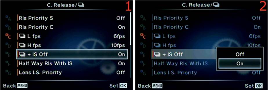
Figure 6.27: Enabling or disabling [Sequential] + IS Off
Use the following steps to enable or disable [Sequential] + IS Off:
1. Choose [Sequential] + IS Off from the C. Release/[FPS] menu and scroll to the right (figure 6.27, image 1).
2. A small window will open with the choices of On or Off (figure 6.27, image 2). If you choose On, the IS system will be disabled. That sounds backwards, but notice that the name of the function is IS Off. You are enabling IS Off, which disables the IS system. If you select Off from the menu, the IS system will work with every frame. The factory default setting is for the IS system to be disabled during sequential shooting.
3. Press the OK button to Set your choice.
Settings Recommendation: I leave this function set to Off because I am not a regular action shooter. If you shoot action frequently, you will have to decide if having stabilized images during sequential shooting is worth the small trade-off in image capture speed. This is a function you will want to test for your style of shooting.
Half Way Rls With IS
When you press the Shutter button halfway down with the Half Way Rls With IS function set to On, the 5-axis image stabilization (IS) system becomes active and stabilizes the image in the viewfinder or on the monitor.
Some people find the sudden cessation of small movements distracting, and others report that it makes them feel queasy. If you are bothered by seeing the IS system in action, you can disable it during subject viewing only. The camera still uses the IS system during the exposure, even if you turn it off for viewing the subject.
I tested this by shooting images with a 1 second shutter speed. When I disabled the IS system during subject viewing by turning off the Half Way Rls With IS function, I was still able to take fairly sharp handheld 1 second exposures. However, when I completely disabled the IS system inShooting Menu 2 > Image Stabilizer > Still Picture, I was not able to make a sharp 1 second exposure. This leads me to believe that the IS system still functions during the actual exposure (i.e., a full press of the Shutter button), even though the user’s manual does not confirm this.
Let’s examine how to turn IS on and off during subject viewing only (i.e., when you press the Shutter button halfway).
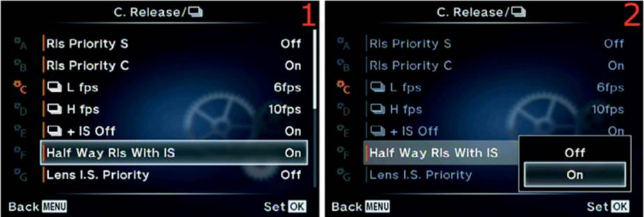
Figure 6.28: Enabling or disabling the IS system during subject viewing only
Use the following steps to enable or disable the IS system during subject viewing in the viewfinder or on the monitor:
1. Choose Half Way Rls With IS from the C. Release/[FPS] menu and scroll to the right (figure 6.28, image 1).
2. A small window will open with the choices of On or Off (figure 6.28, image 2). If you choose On, the camera will use the IS system to stabilize the subject in the viewfinder or on the monitor. If it is set to Off, the camera stabilizes the image only during the actual exposure. The factory default is On.
3. Press the OK button to Set your choice.
Settings Recommendation: I leave this function set to On. I enjoy seeing my subject stabilized in the viewfinder when I hold the Shutter button halfway down. However, you may not like the way it makes you feel, so turn it off. Evidently, the camera will still use the IS system during the exposure. However, I think it is better to have the image stabilized before the exposure so it doesn’t have to be done quickly at the moment of exposure. With fast shutter speeds it may not have time to stabilize. Test this for yourself and form your own opinion.
Lens I.S. Priority
Since the E-M1 is a Micro Four Thirds camera, within a sizable group of other Micro Four Thirds cameras, there are many non-Olympus lens choices. You may own or want to purchase another brand of Micro Four Thirds lens. If the lens has built-in image stabilization, it will work with the in-body stabilization of the E-M1.
Lens I.S. Priority allows you to assign priority to a non-Olympus lens that has stabilization built in. Or you can make the E-M1’s IS system take priority. Let’s see how it is done.
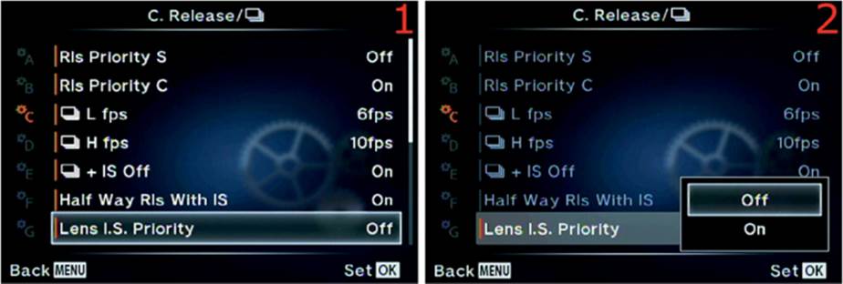
Figure 6.29: Setting the priority for IS to lens or body
Use the following steps to enable Lens I.S. Priority or assign priority to the E-M1’s 5-axis in-body sensor stabilization:
1. Choose Lens I.S. Priority from the C. Release/[FPS] menu and scroll to the right (figure 6.29, image 1).
2. A small window will open with the choices of On or Off (figure 6.29, image 2). If you choose On, the camera will use the I.S. system in the lens to stabilize the subject. If you choose Off, the camera’s 5-axis IS system stabilizes the image instead. The factory default is Off. If you decide to use the in-camera stabilization with a lens that has built-in stabilization, set this function to Off to disable the stabilization in the lens.
3. Press the OK button to Set your choice.
Settings Recommendation: I enjoy M.Zuiko and Zuiko lenses (with my MMF-3 adapter). Therefore, I don’t currently own other brands of Micro Four Thirds lenses, even though there are some mighty appealing lenses out there.
The 5-axis image stabilization in the E-M1 is so amazingly amazing that I am completely amazed! I doubt any other lens stabilization system could match it. Therefore, I prefer to use in-body stabilization.
Release Lag-Time
This function changes the way the camera holds the shutter open. You can use Normal or Short settings. What is the difference? The user’s manual does not say.
Evidently, when the Release Lag-Time is set to Normal, the camera uses a mechanical system to hold the shutter open so you can view the subject. When you switch the setting to Short, the camera appears to switch to an electromagnetic shutter hold. When you partially press the Shutter button immediately after switching, you will hear a distinct click as the camera switches to the alternate system.
When you turn the camera on with Release Lag-Time set to Short, you will hear a distinct click as it switches to the electromagnetic shutter hold system. You cannot hear the click when it is set to Normal.
There are advantages and disadvantages to using the Short setting:
Short setting advantages
• The shutter sound is reduced in the Short setting. If you are shooting a wedding, for instance, and need a quieter shutter, the Short setting may help.
• The Short setting has antishock properties because the shutter is released electromagnetically, instead of mechanically. If you are handholding the camera you may get sharper pictures with Release Lag-Time set to Short.
• There is a shorter lag time for firing the shutter. In Short mode with the Image Stabilizer turned off while you press the Shutter button halfway, the camera can release the shutter in 0.044 second. This allows you to shoot moving objects more quickly. If you are an action shooter, you may want to consider using the Short setting since it makes the camera more responsive.
Short setting disadvantages
• The electromagnetic system does not hold the shutter open as strongly as a mechanical system. If the camera is subjected to a strong shock, the shutter may close and disable viewing of the subject. If that happens, you will have to turn the camera off and back on to use the viewfinder or monitor to view the subject.
• The main disadvantage is reduced battery life. The E-M1’s battery is already not sufficient to provide a full day’s use, in most instances. Reducing the battery life by 20 percent makes that problem even worse. According to Camera & Imaging Products Association (CIPA) standards, Olympus claims the Short setting will reduce the battery life by up to 60 images. If you decide to use the Short setting, you may want to stock up on extra batteries and use an HLD-7 power battery holder, which lets you change the battery that’s in the battery holder while the camera is still powered by its internal battery. Having the camera always powered will prevent you from losing shots in a fast-moving environment.
Now let’s examine how to choose either Normal or Short Release Lag-Time.

Figure 6.30: Choosing a Release Lag-Time
Use the following steps to choose the Normal or Short Release Lag-Time:
1. Choose Release Lag-Time from the C. Release/[FPS] menu and scroll to the right (figure 6.30, image 1).
2. A small window will open with the choices of Normal or Short (figure 6.30, image 2). If you choose Short, the camera will use an electromagnetic shutter release system. The factory default is Normal.
3. Press the OK button to Set your choice.
Settings Recommendation: As a photographer who does not often take action shots, the reduced battery life of Short mode makes me uninterested in it. However, if I were hired to shoot a car race or airplane show, I would set the Release Lag-Time to Short and take extra batteries. The fact that I use an HLD-7 power battery holder on my E-M1 gives me some flexibility for longer battery life. An action shooter who uses Short mode should seriously consider purchasing the HLD-7.
Custom Menu D. Disp/[Sound]/PC
Custom Menu D. Disp/[Sound]/PC contains 20 functions that pertain to the camera displays, sound system, and connectivity with a personal computer (PC).
Let’s look at the location of the settings group on the Custom Menu, then we will consider each of the 20 functions individually.
The D. Disp/[Sound]/PC settings group is the fourth item down on the Custom Menu, as seen in figure 6.31. Use this screen as a reference for opening the group to access the 20 internal functions.
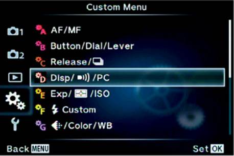
Figure 6.31: The opening menu selection for the D. Disp/[Sound]/PC functions
HDMI
High-definition multimedia interface (HDMI) lets your camera communicate with display devices for showing still pictures and videos. Like slideshows of the old film days, HDMI allows you to use a large screen to show off your work for family and friends (or clients).
The E-M1 has an HDMI type D cable connector under the lower rubber flap on the left side, just above the USB A/V Out port. HDMI is engraved in the rubber flap (figure 6.32A). You will need an HDMI type D to type A cable to plug your camera in to a high-definition television (HDTV) or other HDMI device. HDTVs use a type A connector, and the E-M1 uses a type D connector.
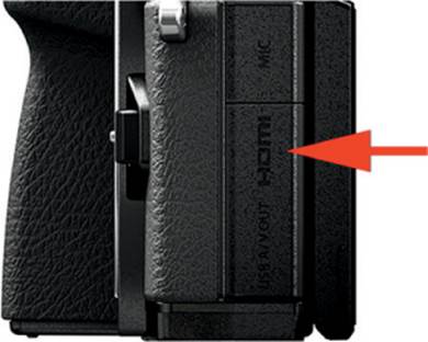
Figure 6.32A: HDMI connector
For your camera to interface with an HDTV or other display device, you will have to match the output frequency from your camera to the input frequency of the HDTV. The camera supports standard HDMI output frequencies, including 1080i, 720p, and 480p/576p. There are two ways to figure out which frequency to use when you plug your camera in to an HDTV:
• Look up the required frequency in your HDTV user’s manual and set the camera to match.
• Plug the camera in to the HDTV and see if it displays pictures. If not, change the HDMI output frequencies until something shows up on the HDTV screen.
Let’s examine how to change the HDMI frequency on the camera.
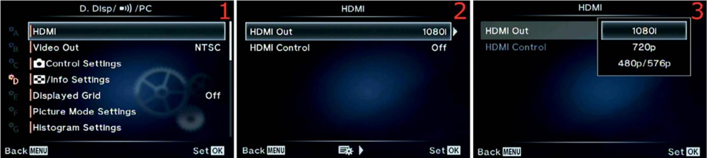
Figure 6.32B: Changing the HDMI output frequency
Use the following steps to change the HDMI output frequency to match an HDMI display:
1. Select HDMI from the D. Disp/[Sound]/PC menu and scroll to the right (figure 6.32B, image 1).
2. Choose HDMI Out from the HDMI menu and scroll to the right (figure 6.32B, image 2).
3. Select one of the listed HDMI output frequencies from the HDMI up/down menu (figure 6.32B, image 3). Most HDTVs support both 1080i and 720p.
4. Press the OK button to Set the output frequency.
The E-M1 supports HDMI-CEC (Consumer Electronics Council) with its HDMI Control function, which allows you to control the camera with the HDTV’s remote control. If your HDTV supports CEC, you can enable it in the camera menu and use the HDTV’s remote control to direct the camera output. Use the following steps to enable HDMI-CEC.
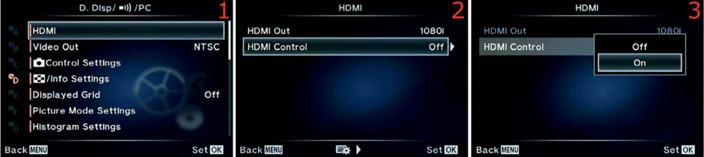
Figure 6.32C: Using HDMI-CEC for camera remote control
1. Select HDMI from the D. Disp/[Sound]/PC menu and scroll to the right (figure 6.32C, image 1).
2. Choose the HDMI Control setting from the HDMI menu and scroll to the right (figure 6.32C, image 2).
3. Select Off or On from the HDMI up/down menu (figure 6.32C, image 3). On enables HDMI-CEC, and Off disables it.
4. Press the OK button to Set your choice.
Settings Recommendation: When I plug my camera into my Vizio flat screen HDTV using the 1080i setting, it works fine. I can even use HDMI-CEC to control the display of images with my HDTV remote control. This is way more fun than the old days of breaking out a slide projector and jumping through hoops to get everything working for a slideshow. I can display videos and still images on my 50 inch (127 cm) HDTV.
Video Out
When you shoot and display video, you should use the standard for your country. There are two primary world standards: National Television System Committee (NTSC) and Phase Alternating Line (PAL). In the United States NTSC is the video standard; in many European countries PAL is the standard.
If you want to make sure which standard to use, download the document called NTSC versus PAL Countries from the Rocky Nook downloadable resources website at this URL: http://www.rockynook.com/OlympusEM1.
Let’s examine how to select one of the video output standards.
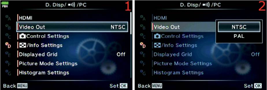
Figure 6.33: Selecting a Video Out standard
Use the following steps to select a Video Out standard for your camera:
1. Select Video Out from the D. Disp/[Sound]/PC menu and scroll to the right (figure 6.33, image 1).
2. Select NTSC or PAL from the Video Out up/down menu (figure 6.33, image 2). Refer to the downloadable NTSC versus PAL Countries document if you are not sure which to use.
3. Press the OK button to Set your choice.
Settings Recommendation: I live in the United States, so I use NTSC. If you are not in the United States and you are not sure which standard to use, check the NTSC versus PAL Countries document. People in the United Kingdom should use PAL.
[Shooting Mode] Control Settings
The E-M1 offers five control panel displays, as discussed further in the chapter Screen Displays for Camera Control. You can select which control panel screens are available when you use one of the modes on the Mode Dial (e.g., P, S, A, M, iAUTO, ART, SCN). The control panel displays are as follows (in alphabetical order):
|
|
ART menu: Use to select one of 12 ART modes or ART BKT (bracketing) |
|
|
Live Control: Use to control image stabilization, picture mode, white balance, shutter release mode, image aspect, record mode, movie quality, flash mode, flash compensation, metering mode, autofocus mode, ISO, face & eye priority, and video sound |
|
|
Live Guide: Use to change color saturation and warmth, brightness, background blur, motion effects, and shooting tips |
|
|
Super Control Panel (SCP): Use to control ISO, white balance, white balance fine-tuning, picture mode, image sharpness, image contrast, flash mode, AF area, AF mode, image saturation, image gradation, face priority, color space, flash intensity, sequential shooting/self-timer, metering mode, Fn1 button assignment, image stabilizer, record mode, and image aspect |
|
|
Scene menu: Use to select one of 25 scene (SCN) modes |
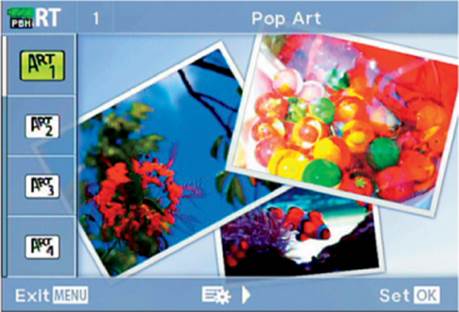
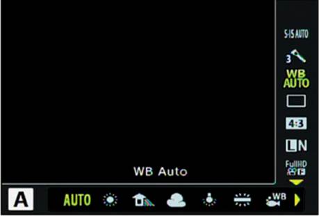
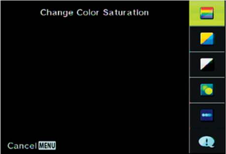
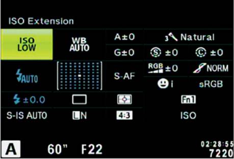
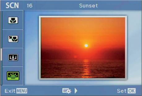
When you have a shooting mode selected on the Mode Dial and have pressed the OK button to open a control panel display, you can press the Info button to move among some of the displays. Table 6.9 shows which control panel displays can be used with which Mode Dial selections when you press the Info button.
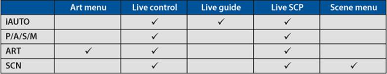
Table 6.9: Control panel displays that can be used with Mode Dial selections
Now let’s examine how to select which control panel displays cycle through with the Info button when you use each mode on the Mode Dial.
Use the following steps to choose control panel displays for Mode Dial selections:
1. Select [Shooting Mode] Control Settings from the D. Disp/[Sound]/PC menu and scroll to the right (figure 6.34, image 1).
2. Select one of the four shooting mode settings—iAUTO, P/A/S/M, ART, or SCN—from the [Shooting Mode] Control Settings up/down menu (figure 6.34, image 2). Figure 6.34, images 3–6, show the choices under each of the four shooting mode settings. Check each item you want to be available under that shooting mode by highlighting it and pressing the OK button to insert a check mark. Press the Info button to scroll through the selected screens for that shooting mode.
3. Press the OK button on each screen (figure 6.34, images 3–6) to Set your choice for that shooting mode.
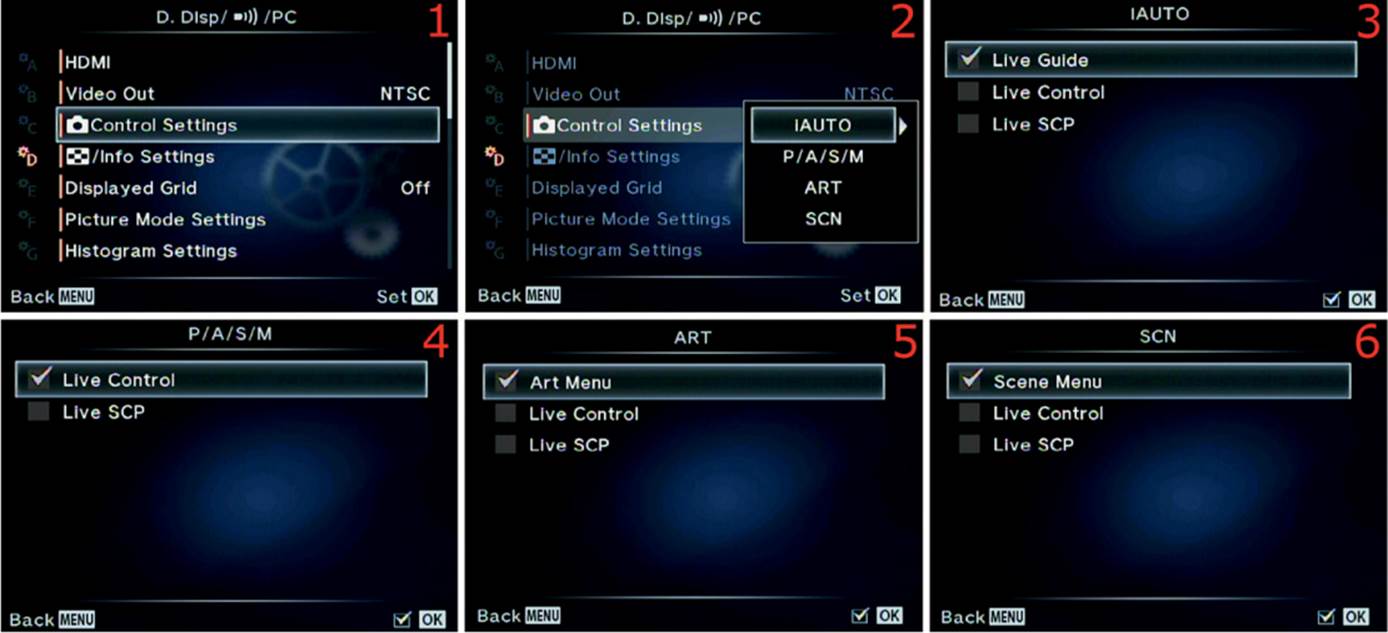
Figure 6.34: Choose control panel displays for Mode Dial selections
Settings Recommendation: I enjoy using Live control. It seems the most intuitive and easy to use, so I like it to be available on any shooting mode I use. Live SCP can also be useful in a similar way, although it is not as intuitive to me. However, I leave it as one of my choices in P/A/S/M and iAUTO modes.
I rarely use the ART or SCN modes. They seem to be useful only when I don’t want to worry about camera settings. Therefore, I ignore the Live Control and Live SCP selections under the ART and SCN screens and place checkmarks next to Art Menu and Scene Menu only.
[Image Review]/Info Settings
The E-M1 can display several different picture information screens. Some of them can be disabled, some cannot. The number of information screens varies with each of these camera modes. The camera also provides five different Image Review screen styles.
The first two entries in the following list describe various information (info) screens, and the final entry describes the style of playback screen you will use when reviewing images:
• ![]() Info: The camera enters this mode when you press the image Playback button (
Info: The camera enters this mode when you press the image Playback button (![]() ). To change the available information screens, press the Info button.
). To change the available information screens, press the Info button.
• LV-Info: This mode is available when you are viewing the subject on the monitor or in the viewfinder. To change the available information screens, press the Info button.
• [Image Review] Settings: After you press the ![]() Playback button, you can rotate the Rear Dial to select from the following choices: Single-frame playback; 4, 9, 25, and 100 frame playback; and Calendar display.
Playback button, you can rotate the Rear Dial to select from the following choices: Single-frame playback; 4, 9, 25, and 100 frame playback; and Calendar display.
Let’s take a look at the screens for each of these modes.
![]() Info (Playback)
Info (Playback)
You can access the five Playback info screens by pressing the ![]() Playback button on the back bottom right of the camera, viewing an image on the screen, then pressing the INFO button repeatedly.
Playback button on the back bottom right of the camera, viewing an image on the screen, then pressing the INFO button repeatedly.
The following list, called the Playback info list of screens, provides an overview of the six available screens you can use when you view images on the monitor.
Playback info list of screens
|
|
Standard Image Review: This basic screen displays the following: Date and time, image number, frame number, image aspect, and record mode. This screen cannot be disabled. |
|
|
Image Only: This is the most basic screen. It shows only a picture of the subject with no camera or shooting information. This is great for judging the quality of the image with no distractions. This optional screen must be selected (checked) under Info Settings > |
|
|
Overall: This more complex screen displays a number of informational items. The following descriptions have values in parenthesis to help you identify the item in the figure: • Exposure mode (A) • Shutter speed (30) • Aperture (f/2.8) • Metering mode (meter symbol) • ± compensation (+1.3) • Lens focal length (32mm) • White balance mode (Capture WB 1) • White balance adjustments (A±0, G±0) • ISO (LOW) • Color space (sRGB) • Picture Mode (Natural) • Image megapixel size (4608×3456) • JPEG compression ratio (1/4) • Image aspect (4:3) • Record mode (LF) • Image number (100–0134) • Frame number (116) • Date (2014.06.30) • Time (09:34) • Luminance histogram (white graph) • RGB channel histograms (red, green, and blue graphs) • Thumbnail image display with AF point shown The orange around the subject represents an area that is blown out to pure white; blue represents a totally underexposed area. We will discuss how to use this in the upcoming Highlight&Shadow item. This optional screen must be selected (checked) under Info Settings > |
|
|
Histogram: The luminance histogram displays a bell curve graph that shows the dynamic range (from light to shadow) in the image. The histogram is very important to understand and use. If the graph is cut off on the left side, some areas are completely black and have no detail. If the graph is cut off on the right side, as seen here, some areas have become pure white with no detail. This optional screen must be selected (checked) under Info Settings > |
|
|
Highlight&Shadow: This screen is useful when you are shooting in very bright light or when the dynamic range of the scene exceeds the ability of the sensor to capture the full shadow to highlight range. The screen shows any areas where there is no detail in the image by repeatedly blinking from orange to white for overexposed areas, or from blue to white for underexposed areas. Some people call this blink mode. A smaller version of this screen is shown as a thumbnail in the Overall screen (discussed previously). This optional screen must be selected (checked) under Info Settings > |
|
|
Light Box: This screen allows you to view a portion of two images at once for comparison purposes. To use the screen, select it with the INFO button while an image is being displayed. Ignore the image on the left side for now. Use the Arrow pad left and right keys to scroll through your pictures until you find one you want to compare. The frame number of the image will appear on the bottom-right corner of each partial image. Notice as you scroll that the image on the right is the only one that changes. When you find the first image you want to compare, press the OK button, and the selected picture will appear on the left. Again, scroll left or right with the Arrow pad keys until you find the second image you want to compare. After both images are displayed, you can zoom in from 1x to 14x and compare them by turning the Rear Dial. The amount of magnification will be displayed on the bottom left of the dual-image screen. This optional screen must be selected (checked) under Info Settings > |
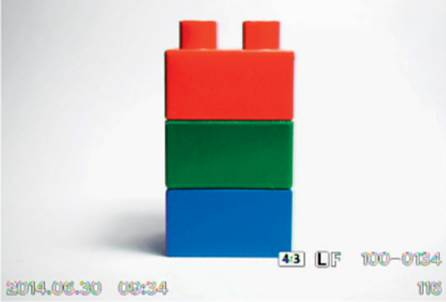
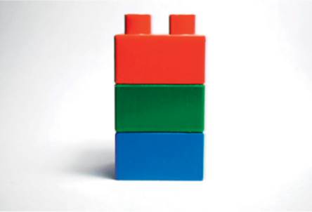
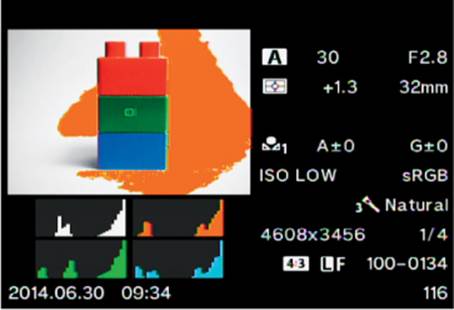
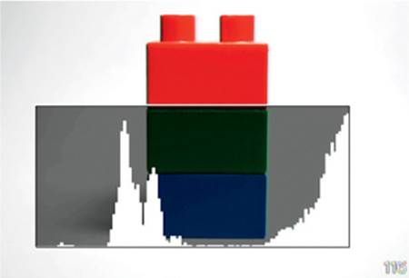

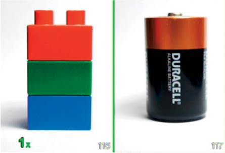
The factory default setting is for Image Only and Overall to be enabled and for Histogram, Highlight&Shadow, and Light Box to be disabled. The Standard Image Review screen is always available and cannot be disabled.
Let’s see how to select information screens for ![]() Info.
Info.
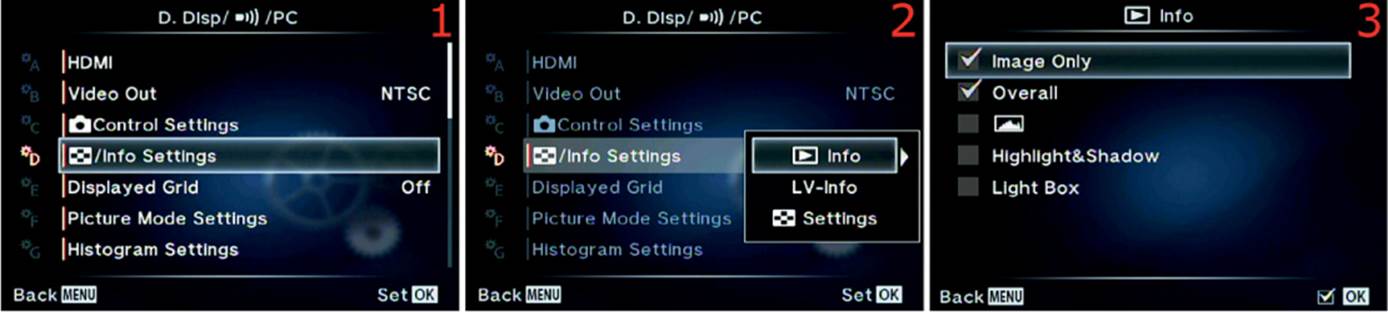
Figure 6.35G: ![]() Info screen choices
Info screen choices
Use the following steps to enable or disable information screens for ![]() Info:
Info:
1. Select [Image Review]/Info Settings from the D. Disp/[Sound]/PC menu and scroll to the right (figure 6.35G, image 1).
2. Select the ![]() Info setting from the [Image Review]/Info Settings menu and scroll to the right (figure 6.35G, image 2).
Info setting from the [Image Review]/Info Settings menu and scroll to the right (figure 6.35G, image 2).
3. You will see five information screen choices (figure 6.35G, image 3). On a new camera, only the first two will be checked. Refer to the Playback info list of screens and place a check mark to the left of the screen you want to use. To add or remove a check mark, simply highlight the choice and press the OK button.
4. When you insert a check mark, the camera automatically saves the choice. Press the Menu button to return to the previous screen.
Settings Recommendation: I set my camera to have all the ![]() Info screens available. They are all useful!
Info screens available. They are all useful!
Now let’s consider the Live View info screens.
Live View (LV) Info
The Live View info screens have similar functionality to the ![]() Info screens, except they are live, based on the subject that is displayed on the monitor instead of an existing picture.
Info screens, except they are live, based on the subject that is displayed on the monitor instead of an existing picture.
There are five Live View info screens, with four of them available as the factory default. One of the five screens is initially disabled. Here is an examination of the five screens and their functionalities.
Live View info list of screens
|
|
Standard Live View: This screen is always available and cannot be disabled. It provides basic shooting and exposure information, depending on which Mode Dial setting you are using. Some of the settings shown on the screen include the following: Face priority, sound setting, lens focal length, in-focus indicator, image stabilization mode, picture mode, white balance mode, ISO, point of focus (AF point), record mode, video mode, mode dial setting, shutter speed, aperture, ± compensation, exposure indicator scale, time, and frame number. |
|
|
Histogram: The luminance histogram is a small bell curve graph in the lower part of the screen that shows the dynamic range (from light to shadow) in the image. The screen also contains a subset of the information found on the Standard Live View screen (previously discussed), with a few omissions, and it has a luminance histogram. This optional screen must be selected (checked) under Info Settings > LV-Info. |
|
|
Highlight&Shadow: This screen is useful when you are shooting in very bright light or when the dynamic range of the scene exceeds the ability of the sensor to capture the full shadow to highlight range. The screen shows any blown-out highlight areas—where the image has become pure white with no detail—by continuously displaying orange where the highlight detail has disappeared. If the image is underexposed and some areas of the subject have gone to pure black (no dark detail), those areas will be blue. It doesnot blink as described for the |
|
|
Image Only: This is the most basic screen. It shows only what the lens currently sees, with no camera or shooting information. This is great for judging the potential quality of the image with no distractions. This optional screen must be selected (checked) underInfo Settings > LV-Info. |
|
|
Level Gauge: This screen allows you to level your camera both horizontally and vertically. As you move the camera off level, you will see white squares appear in the two level indicators, showing the degree and direction of level errors. My camera lens is pointed down slightly, and my camera body is rotated counterclockwise. The Level Gauge screen also contains basic exposure and camera settings. This optional screen must be selected (checked) under Info Settings > LV-Info. |
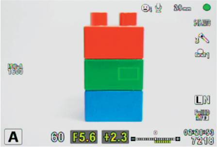
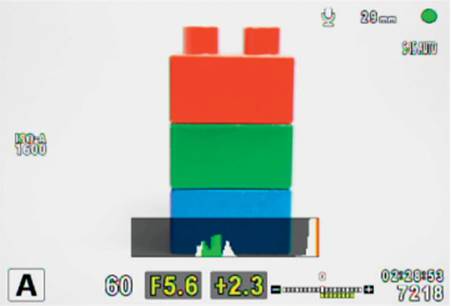
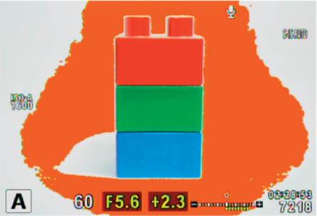

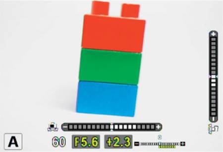
The factory default setting is for all of the LV-Info screens—except the Highlight&Shadow info screen—to be enabled.
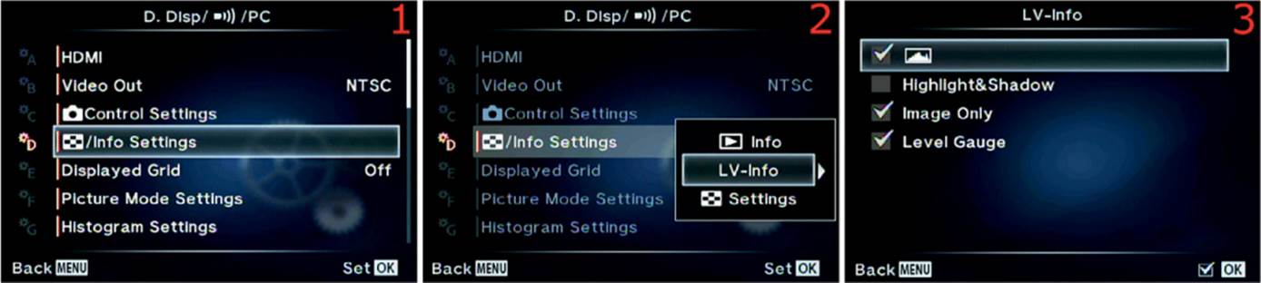
Figure 6.35M: LV-Info screen choices
Use the following steps to enable or disable information screens for LV-info:
1. Select [Image Review]/Info Settings from the D. Disp/[Sound]/PC menu and scroll to the right (figure 6.35M, image 1).
2. Select the LV-Info setting from the [Image Review]/Info Settings menu and scroll to the right (figure 6.35M, image 2).
3. You will see four information screen choices (figure 6.35M, image 3). On a new camera, everything except Highlight&Shadow will be checked. Refer to the Live View info list of screens and place a check mark to the left of the screen you want to use. To add or remove a check mark, simply highlight the choice and press the OK button.
4. When you insert a check mark, the camera automatically saves the choice. Press the Menu button to return to the previous screen.
Settings Recommendation: I set my camera to have all the LV-Info screens available. As with the ![]() Info screens, they are all quite useful to me. I especially like using the Highlight&Shadow screen when I am shooting in difficult lighting environments.
Info screens, they are all quite useful to me. I especially like using the Highlight&Shadow screen when I am shooting in difficult lighting environments.
Now let’s consider the [Image Review] Settings screens.
[Image Review] Settings
The Image Review screens provide different ways of viewing images on your memory card. You can view a single image or groups of images in configurations of 4, 9, 25, and 100 images per screen. There is also a Calendar format.
From the factory, only the 25 image and Calendar formats are available, but we will examine how to select the other formats.
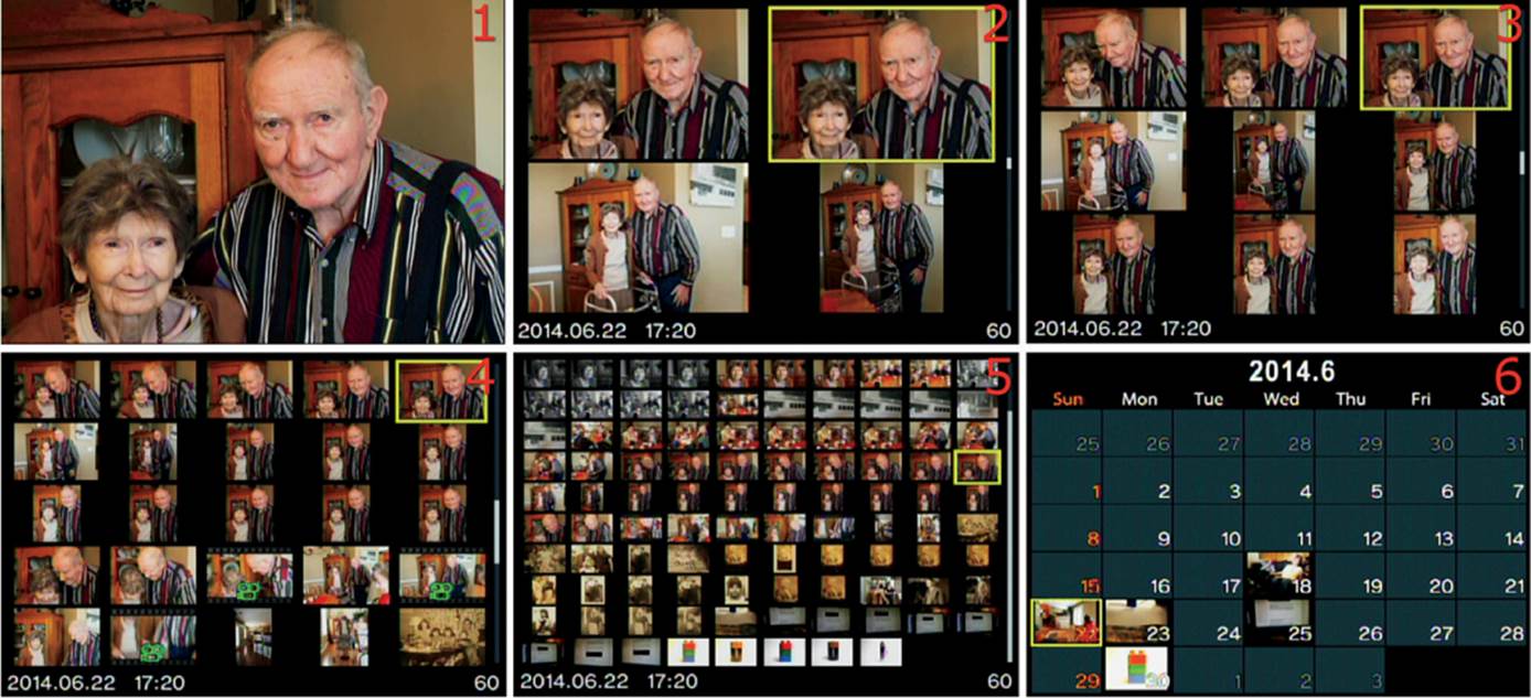
Figure 6.35N: [Image Review] Settings
You can rotate the Rear Dial clockwise to see six views of the images on the memory card (turning the Rear Dial counterclockwise zooms in on a single image with magnifications from 1x to 14x).
Figure 6.35N, images 1–5, shows the views for 1, 4, 9, 25, and 100 images. The Calendar view (figure 6.35N, image 6) allows you to scroll to a date and select images that were taken on that day. If there are no thumbnail images on a date, no pictures were taken that day.
Let’s examine how to enable and disable the image view screens.
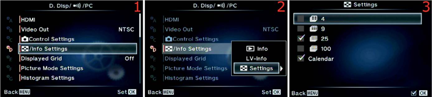
Figure 6.35O: [Image Review] Setting choices
Use the following steps to enable or disable image view screens for [Image Review] Settings:
1. Select [Image Review]/Info Settings from the D. Disp/[Sound]/PC menu and scroll to the right (figure 6.35O, image 1).
2. Select [Image Review] Settings from the [Image Review]/Info Settings menu and scroll to the right (figure 6.35O, image 2).
3. You will be see five information screen choices (figure 6.35O, image 3). On a new camera, 4, 9, and 100 will not be checked. Place a check mark to the left of the image review screen type you want to use. To add or remove a check mark, simply highlight the choice and press the OK button.
4. When you insert a check mark, the camera automatically saves the choice. Press the Menu button to return to the previous screen.
Settings Recommendation: I set my camera to use the 4, 9, 25, and Calendar image review screens. The 100 image view is a little small for my eyes, but if you look carefully you can make out enough detail to choose an image. Experiment with these settings and see which are most useful to you.
Displayed Grid
This function allows you to display five types of grids on your camera monitor or in the electronic viewfinder (EVF). Let’s examine each one.
Here is a description of the five grid types shown in figure 6.36A:
• Image 1 shows the Live View Image Only screen with no grid lines.
• Image 2 shows a full-screen grid that is useful for many types of camera leveling.
• Image 3 shows a grid that is more centered on the screen. It is almost, but not quite, in the rule of thirds format.
• Image 4 shows a cross-screen grid that is similar to a rifle scope.
• Image 5 shows an X-pattern grid that identifies the center of the screen and uses a receding lines effect.
• Image 6 shows grid lines in the top and bottom areas of the screen. This pattern closely resembles the 16:9 aspect ratio of high-definition movies and some still images.
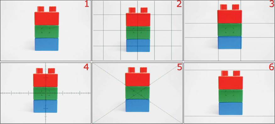
Figure 6.36A: The normal Live View Image Only screen and five types of grids
Now let’s see how to select a grid pattern for the monitor and EVF.

Figure 6.36B: Selecting a grid pattern for the monitor or EVF
Use the following steps to choose your favorite grid pattern for the EVF and monitor:
1. Select Displayed Grid from the D. Disp/[Sound]/PC menu and scroll to the right (figure 6.36B, image 1).
2. Select one of the five grid patterns, or Off, from the Displayed Grid menu (figure 6.36B, image 2).
3. Press the OK button to Set the grid pattern.
Settings Recommendation: I like to use the grid pattern shown in figure 6.36A, image 2, which is useful for leveling the horizon, keeping the lens level for architecture, and watching out for perspective distortion. I have never had a camera with so many patterns. Play with each of them and see which ones work best for you.
Picture Mode Settings
The camera has a choice of 20 Picture Modes, as discussed in the Shooting Menu 1 chapter. If you do not use some of the Picture Modes, you can use this function to hide them from the Shooting Menu 1 > Picture Mode menu and any camera screens that allow you to choose a Picture Mode.
Let’s say you are not interested in using the Art Picture Modes. You could simply un-check them from the Picture Mode Settings menu and they will disappear from any menu or screen that normally displays a choice of Picture Modes.
Let’s examine how to enable and disable Picture Modes.
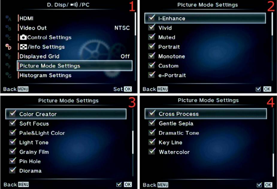
Figure 6.37: Enabling or disabling Picture Modes
Use the following steps to enable or disable Picture Modes from appearing on the camera menus and screens:
1. Select Picture Mode Settings from the D. Disp/[Sound]/PC menu and scroll to the right (figure 6.37, image 1).
2. Scroll up or down with the Arrow pad and highlight any Picture Modes you want to disable or enable. The default is to have all Picture Modes available (figure 6.37, images 2–4). Press the OK button to uncheck any modes that you do not want to use, or to check any modes you want to restore.
3. When you insert a check mark, the camera automatically saves the choice. Press the Menu button to return to the Picture Mode Settings screen.
Settings Recommendation: I leave all the Picture Modes checked and available. Although I don’t often use them, I play around with them sometimes. The E-M1 is a fun camera because it has many effects for JPEG pictures. If you are a RAW shooter, Picture Modes are not of much interest because you can apply effects after the fact.
Histogram Settings
The Histogram display on the camera provides a window that shows the cutoff points for losing all detail in an image, which helps you determine how well the image is exposed. The left side of the Histogram window represents shadows, and the right side represents highlights.
The range of light that the camera can capture is symbolized by a Histogram scale that goes from 0 to 255, where 0 represents total black with no detail, and 255 represents pure white with no detail. Figure 6.38A shows a histogram in the shape of a bell curve. You can see the range of 0–255 along the horizontal axis.
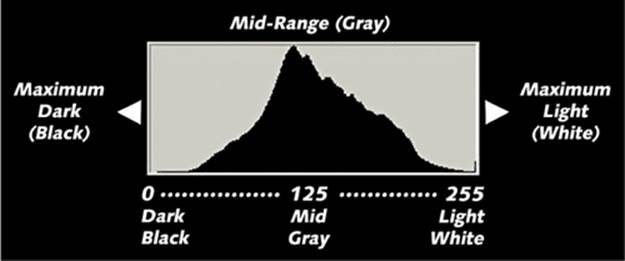
Figure 6.38A: The Histogram scale represents total black (0) to pure white (255)
Using the Histogram
You can use the Histogram to protect your images from over- and underexposure. Figure 6.38B shows how the Histogram reacts to conditions ranging from underexposed to well exposed to overexposed.
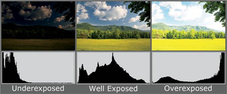
Figure 6.38B: The Histogram scale can help you expose images properly
Notice how the bell curve graph is crammed to the left (clipped) for the underexposed image. It is cut off midpeak. The clipping indicates that some of the image is pure black (0), with no detail, and the overall image may be too dark.
In the well-exposed image in the middle, you can see that the graph is centered between the left (shadow) and right (highlight) sides.
The graph of the overexposed image is clipped off on the right, at the middle of the peak, and some of the image has become pure white.
Whenever you see the Histogram graph clipped on the left, the image may be too dark; if it is clipped on the right, the image may be too light. If the Histogram is clipped on both the shadow and highlight sides, there is too much light range (contrast) for the camera to capture all detail in the dark and light areas within a single image.
In that case, you must use either high dynamic range (HDR) photography, where multiple images are taken with different exposures then combined, or expose for the highlights to prevent the histogram from clipping on the right side. Notice how the Histogram graph just touches the left and right sides of the Histogram window in the well-exposed image (figure 6.38B). If there is too much contrast in the image, you may have to accept having the Histogram just touch the right side (highlight) only and allow clipping to occur on the left side. That is called exposing for the highlights.
When the Histogram graph just touches the right side without clipping, but it is clipped on the left, there will be dark shadows in the image. That looks normal to our eyes. We expect shadows to be dark, but we do not expect to see a lack of highlight detail.
Use the normal exposure system—shutter speed, aperture, and ISO—to move the histogram to the left or right. You may need to use the ± Exposure Compensation system to fine-tune the position of the Histogram graph for the best exposure. Fortunately, the camera gives you a Live Histogram display, which appears when you repeatedly press the Info button with the subject on the monitor (figure 6.38C) or in the viewfinder.
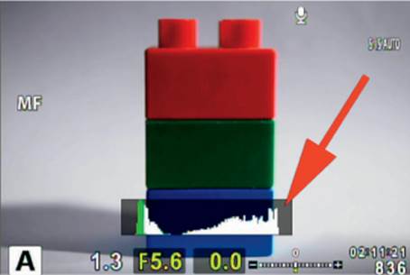
Figure 6.38C: The Live Histogram display for a well-exposed natural light exposure
The E-M1 also gives you control over how conservatively the histogram warns you of over- and underexposure. Normally you will leave the camera set so that pure black equals 0 and pure white equals 255. However, some photographers may want a little padding on either side of the histogram for extra protection. You can adjust the Histogram window size (range) so it no longer ranges from 0 to 255. Instead it can be moved by up to 10 increments on each side (a maximum of 10 to 245).
Let’s examine how to change this setting.
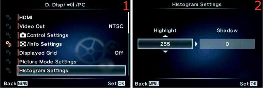
Figure 6.38D: Making the Histogram more or less conservative
Use these steps to change the range the Histogram uses to warn you of exposure problems:
1. Select Histogram Settings from the D. Disp/[Sound]/PC menu and scroll to the right (figure 6.38D, image 1).
2. Select a value for Highlight from 245 to 255 and a value for Shadow from 0 to 10 from the up/down menus (figure 6.38D, image 2).
3. Press the OK button to Set the new Histogram values.
Settings Recommendation: If you are ultraconservative in your exposures, you may want to adjust this setting. Otherwise, leave it at the industry standard of 0–255, which is what I use.
Mode Guide
The Mode Guide reminds you of the purpose of each setting on the Mode Dial on top of the camera. Each of the modes has a help reminder, as follows:
Modes on Mode Dial
• P: The camera sets the aperture and shutter speed automatically.
• A: You set the aperture manually.
• S: You set the shutter speed manually.
• M: You set the aperture and shutter speed manually.
• [Movie]: Start recording a movie, and take a picture (during the movie).
• [Image Templates]: The camera combines two or more template images into one image.
• SCN: The camera automatically applies settings to the Scene Mode you select.
• ART: Apply creative effects to your images.
• iAUTO: The camera selects the ideal mode, and the Live Guide menu is accessible.
Figure 6.39A shows the Mode Guide reminder for Aperture-priority (A) mode. Simply selecting a setting by turning the Mode Dial will immediately display the help reminder for that mode on the rear monitor only.
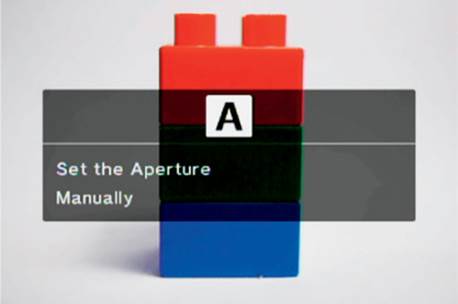
Figure 6.39A: Mode Guide reminder for Aperture-priority (A) mode
Let’s see how to enable or disable the Mode Guide help reminders.
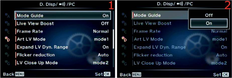
Figure 6.39B: Enabling or disabling the Mode Guide reminder system
Use the following steps to turn the Mode Guide help system on or off:
1. Select Mode Guide from the D. Disp/[Sound]/PC menu and scroll to the right (figure 6.39B, image 1).
2. Select Off or On from the up/down menu (figure 6.39B, image 2). The factory default is On.
3. Press the OK button to Set the Mode Guide value.
Settings Recommendation: I am torn about this setting. I do not need help with understanding what P, S, A, and M modes do. However, the functionality of some other modes, which I rarely use, might slip my mind. For now I have this set to On and tolerate the help screen when I turn the Mode Dial. However, it does aggravate me nearly every time I use the dial. If you are not familiar with what each mode accomplishes, you might want to leave the Mode Guide turned on.
Live View Boost
Live View Boost makes the subject look bright on the monitor, regardless of how little ambient light there may be. It is amazingly capable of artificially opening up the shadows on the monitor and in the viewfinder. If the most important thing is to be able to see the subject in low light, you may want to enable this function. If carefully controlled exposures are more important, do not enable it.
Live View Boost does not affect the exposure of the picture; it affects only how the image appears on the monitor and in the viewfinder. Unfortunately controls such as ± Exposure Compensation, although they still work normally to control exposure, will not display their effects on the screens when Live View Boost is enabled.
Live View Boost even prevents the Live Histogram display from updating correctly for Exposure Compensation changes. With Live View Boost enabled, the Live Histogram is limited to displaying the exposure the camera would provide without compensation. If you turn the dial for Exposure Compensation, the Histogram will not adjust and show the true exposure value, which could easily lead to under- or overexposure.
Let’s examine how to turn Live View Boost on and off.
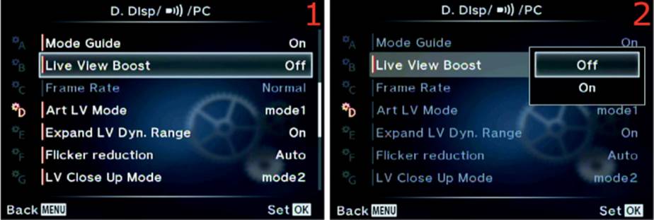
Figure 6.40: Enabling or disabling Live View Boost
Use these steps to turn Live View Boost on or off:
1. Select Live View Boost from the D. Disp/[Sound]/PC menu and scroll to the right (figure 6.40, image 1).
2. Select Off or On from the up/down menu (figure 6.40, image 2). The factory default is Off.
3. Press the OK button to Set the value.
Settings Recommendation: When you turn the dial for Exposure Compensation, you expect to see the image brighten or darken until it looks just right. You will not see the brightening or darkening effect with Exposure Compensation when Live View Boost is enabled because the screen is doing its best to brighten the subject to the max. Also, the Live Histogram will not update correctly for compensation.
If you are in a dark room trying to shoot a subject by candlelight, Live View Boost can help you see the subject. However, I leave Live View Boost set to Off.
Frame Rate
The E-M1 has a frame lag of merely 0.029 second between each frame you shoot. That makes the camera’s electronic viewfinders (EVF) one of the fastest on the market today, with much less blackout (flicker) between frames. However, you can speed up the Frame Rate (the lag between frames) even more while shooting, but the display quality on the monitor and in the viewfinder will be reduced. It does not affect the quality of the images you take.
Decreasing the frame lag setting to High apparently lowers the camera’s processing time to the point that the image display may have marginally less quality. However, for the trade-off in quality of the displayed image, you will experience less frame lag.
Note: The Frame Rate setting will be grayed out and unavailable if focus Peaking is set to On (Custom Menu > A. AF/MF > MF Assist > Peaking).
Let’s examine how to configure the Frame Rate setting.
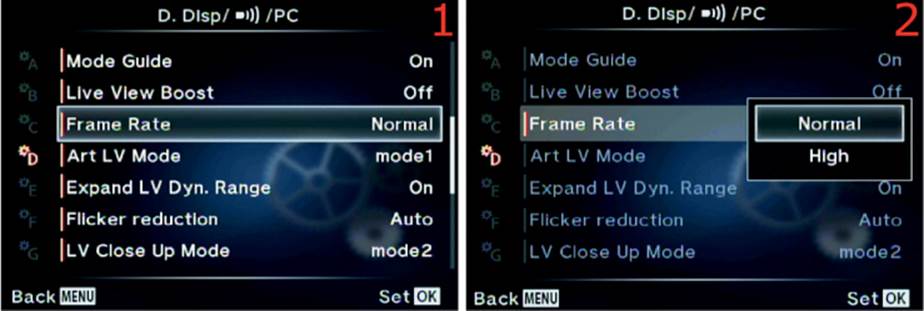
Figure 6.41: Setting the Frame Rate (lag time between frames)
Use the following steps to change the camera’s frame lag:
1. Select Frame Rate from the D. Disp/[Sound]/PC menu and scroll to the right (figure 6.41, image 1).
2. Select Normal or High from the up/down menu (figure 6.41, image 2). The factory default is Normal.
3. Press the OK button to Set the value.
Settings Recommendation: As a nature shooter, I find that the camera is plenty fast, and I like to keep the image quality high in the camera displays while I shoot. However, if you are an action shooter and are photographing an event at up to 10 fps, you may want the fastest EVF display possible and will not mind slightly less quality as the images zip by in burst mode.
Art LV Mode
Using an Art filter places high demands on the camera microprocessor. That can lead to jerkiness in the electronic viewfinder (EVF) because it slows down the frame rate when you shoot quickly.
To counteract that demand, you can set the camera so it does not fully display the effect of the Art filter when you have the Shutter button pressed halfway down (mode2). In mode1 the camera displays the full Art filter effect and ignores the reduced EVF frame rate. That doesn’t mean you won’t see the effect of the Art filter on the monitor and in the viewfinder in mode2—it simply means the effect may not be as pronounced because the camera shoots images so quickly. This function does not affect the look of the pictures you take, just how they are displayed on the camera screens while you shoot.
The point of this function is to allow you to have a faster frame rate, even when you shoot with microprocessor-intensive Art filters.
Note: The camera user’s manual has an error, or is out of date, on page 93 where this function is discussed. There it states that this function completely turns off the Art filter when you hold the Shutter button halfway down in mode2. You will still see the effect of the Art filter on the camera display screens, but they may not be quite as deep and the refresh rate will be faster when you are using mode2. The camera’s help text for mode2 reports the following in firmware version 1.4: “The Art Filter effect is lightened on the LCD and the viewing frame rate is faster.”
Let’s examine how to select one of the two modes.
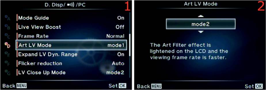
Figure 6.42: Selecting an Art LV Mode for the best frame refresh rate while using Art filters
Use the following steps to modify the Art LV Mode setting:
1. Select Art LV Mode from the D. Disp/[Sound]/PC menu and scroll to the right (figure 6.42, image 1).
2. Select mode1 or mode2 from the up/down menu (figure 6.42, image 2). The factory default is mode1.
3. Press the OK button to Set the value.
Settings Recommendation: Since this function does not affect the pictures you take, only the display screens, you will need to decide if you really need the effect of an Art mode to display with its full effect while you shoot multiple pictures. Most people would rather not have their camera slow down while they shoot quickly, so my recommendation is to use mode2. Of course, if you rarely or never use the Art filters while shooting bursts of images, this function may not be useful to you. I leave mine set to mode2 for the best refresh rate in case I decide to blast off a bunch of Art Grainy Film black-and-white images. If I am shooting with an Art mode at several frames per second, I don’t really need to examine each image as it flies by!
Expand LV Dyn. Range
When you set this function to On the camera displays a preview of how the final combined image will look when you use HDR1 or HDR2 mode (firmware version 1.4). It has no effect when you use the other HDR modes (e.g., 3F 2.0EV, 5F 3.0EV).
If you have Expand LV Dyn. Range set to On and switch HDR1 or HDR2 on or off with the Sequential shooting/Self-timer/HDR button, you will see the sample HDR image in the viewfinder or on the monitor.
With this function set to On, the camera expands the dynamic range of the monitor and viewfinder—it tones down the highlights and opens the shadows—so the display image more closely resembles the final combined HDR image. It may not be exactly the same as the final image when there is a wide range of light, but it is much closer than the boosted brightness display you normally see. If this function is set to On and you switch back and forth between the final combined HDR image and the subject displayed on either of the display screens, you will see that they are fairly close in dynamic range.
When this setting is Off, the camera displays the normal boosted brightness view on the monitor or in the viewfinder when you switch to HDR1 or HDR2.
Both the On and Off settings allow you to view each of the three images while the camera builds the HDR image.
Let’s examine how the images are shown on the display screens in both modes.
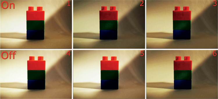
Figure 6.43A: Monitor view with Expand LV Dyn. Range set to On and Off
In figure 6.43A, images 1–3, Expand LV Dyn. Range is set to On, and in images 4–6 it is set to Off. In both rows, the final images (3 and 6) are the actual HDR combinations when I used HDR1 mode. Let’s examine both modes more closely:
• On: In the top row (figure 6.43A, images 1–3), image 1 is the bright image the monitor normally displays. In image 2, which appears as soon as the camera enters HDR1 or HDR2 mode, you can see that the HDR preview image has toned down the highlights and opened up the shadows—that is, there is a greater dynamic range. Image 3 is the actual HDR combination in HDR1 mode. Notice that images 2 and 3 closely resemble each other. That’s because Expand LV Dyn. Range was set to On, and the preview in image 2 closely resembles the final HDR image combination (image 3).
• Off: In the bottom row (figure 6.43A, images 4–6), image 4 is the bright image the monitor normally displays. In image 5 you can see that there is no HDR preview image when the camera is set to HDR1 or HDR2 mode. Instead, images 4 and 5 are basically identical. In image 6 the HDR combined image does not resemble image 5. This illustrates that the camera did not expand the dynamic range in image 5. It is not an HDR preview image, whereas image 2 clearly is.
Now let’s examine how to choose a setting for Expand LV Dyn. Range.
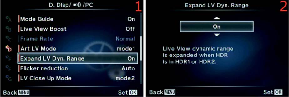
Figure 6.43B: Choosing a setting for Expand LV Dyn. Range
Use the following steps to modify the Expand LV Dyn. Range setting:
1. Select Expand LV Dyn. Range from the D. Disp/[Sound]/PC menu and scroll to the right (figure 6.43B, image 1).
2. Select On or Off from the up/down menu (figure 6.43B, image 2). The factory default is On.
3. Press the OK button to Set the value.
Settings Recommendation: It is a good idea to preview the approximate look of the final HDR image. Therefore, I set my camera to On for Expand LV Dyn. Range.
Flicker Reduction
When you take pictures under certain types of lighting, such as fluorescent lamps, the camera monitor and viewfinder may tend to display dark bands moving through them. This flickering is caused by the normal fluctuations in the electrical flow of alternating current (the frequency of the current is measured in hertz, or Hz) moving through the lamps.
The camera has three modes for reducing flicker: Auto, 50Hz, and 60Hz. It defaults to Auto. Some areas of the world use 50Hz, and others use 60Hz. In Auto the camera will try to determine which frequency is best for flicker reduction, or you can choose 50Hz or 60Hz and see which works best.
Let’s examine how to choose one of the Flicker Reduction modes.
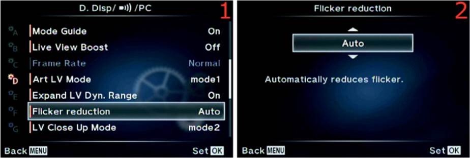
Figure 6.44: Choosing the best way to reduce flicker in the camera display screens
Use the following steps to modify the Flicker Reduction setting:
1. Select Flicker Reduction from the D. Disp/[Sound]/PC menu and scroll to the right (figure 6.44, image 1).
2. Select Auto, 50Hz, or 60Hz from the up/down menu (figure 6.44, image 2). The factory default is On.
3. Press the OK button to Set the value.
Settings Recommendation: A bane of digital photography with an electronic viewfinder or monitor is flickering under fluorescent lights. I have never been able to eliminate the bands that move through the screens, but you can try the three different adjustments and see if they help.
Don’t worry, though, because other than being a bit of an aggravation while shooting, the flickering is not captured in the image.
LV Close Up Mode
As discussed in the previous Button Functions section of this chapter and in the appendix (Button Tasks), you can assign the Magnify task to one of the Button functions (e.g., Fn1, Fn2). The Magnify task will let one of the camera buttons zoom in to, or magnify, the subject and show an extreme closeup. This is a great focus aid because you can see a small portion of the subject up close while using autofocus.
The camera defaults to mode2 of the LV Close Up Mode, which allows the autofocus system to work while the subject remains magnified on the enlarged Live View screen.
Mode1 causes the magnification to go away before autofocus will work. The image will zoom back out to normal when you press the Shutter button to initiate autofocus, and it will force you to autofocus with no magnification.
Manual focus can be used with full magnification in either mode1 or mode2. Let’s examine how to select one of the two LV Close Up Modes.
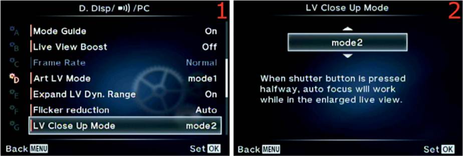
Figure 6.45: Choosing an LV Close Up Mode
Use the following steps to modify the LV Close Up Mode setting:
1. Select LV Close Up Mode from the D. Disp/[Sound]/PC menu and scroll to the right (figure 6.45, image 1).
2. Select mode1 or mode2 from the up/down menu (figure 6.45, image 2). The factory default is mode2, and AF works during magnification.
3. Press the OK button to Set the value.
Settings Recommendation: One of the primary reasons I want to zoom in or magnify the subject is to make sure autofocus is working well, so I leave this function set to mode2. However, if you want to zoom in on the subject for a different reason and would rather have autofocus work only when the camera is zoomed out to normal, use mode2.
[Aperture] Lock
[Aperture] Lock extends the power of the Preview button. Recall that if the Preview button is not assigned to some other task, it will stop down (close) the aperture while it is depressed so you can see the depth of field (zone of sharp focus) in your image. [Aperture] Lock lets you do the same thing, except you don’t have to keep the Preview button depressed to preview the stopped-down aperture. Instead, you can press the Preview button once to lock the aperture in its stopped-down position, allowing you to see the depth of field, then press it again to unlock the aperture and open it back up to maximum size for bright subject viewing.
Let’s examine how to configure [Aperture] Lock.
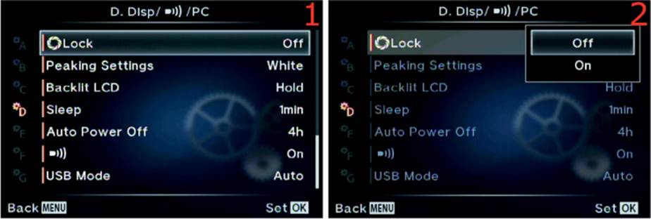
Figure 6.45A: Enabling or disabling the [Aperture] Lock function
Use the following steps to enable or disable the [Aperture] Lock function:
1. Select [Aperture] Lock from the D. Disp/[Sound]/PC menu and scroll to the right (figure 6.45A, image 1).
2. Select On or Off from the up/down menu (figure 6.45A, image 2). The factory default is Off.
3. Press the OK button to Set the value.
Settings Recommendation: Normally, the regular way a Preview button provides depth of field (DOF) preview is fine. Most of the time I leave this function set to Off. However, when I am working with macro shots and want to fine-tune where the depth of field falls within my image, I find it convenient to set this function to On and use [Aperture] Lock to stop down the aperture while I use manual focus to move the depth of field back and forth until it is exactly where I want it. I love the fact that the electronic viewfinder gets rid of most of the darkness that results from a smaller aperture so I can see how to manipulate the DOF until it is exactly where I want it to be. This is a very convenient function for people who like to use hyperfocal focusing and still want to visually confirm the DOF boundaries.
Peaking Settings
Peaking allows you to manually focus the subject by surrounding the in-focus areas in a white or black outline. The default is white, but you can change it to black if you want to.
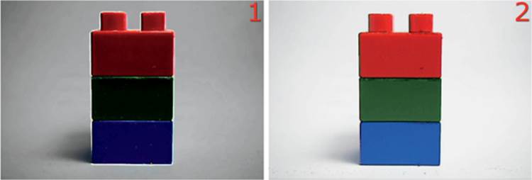
Figure 6.46A: White (image 1) and Black (image 2) Peaking
White Peaking slightly darkens the entire image and boosts the contrast so you can more easily see the white borders of the in-focus areas (figure 6.46A, image 1). Black Peaking lightens the image and raises the contrast so you can more easily see the black borders of the in-focus areas (figure 6.46A, image 2).
Note: You can enable or disable Peaking with the Custom Menu > A. AF/MF > MF Assist > Peaking function.
Let’s examine how to select White or Black for when manual-focus Peaking is active.
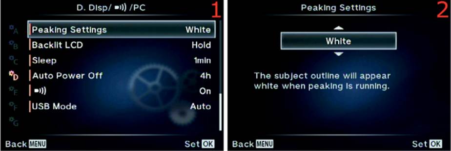
Figure 6.46B: Selecting White or Black Peaking
Use the following steps to modify the Peaking Settings function:
1. Select Peaking Settings from the D. Disp/[Sound]/PC menu and scroll to the right (figure 6.46B, image 1).
2. Select White or Black from the up/down menu (figure 6.46B, image 2). Both colors are useful for enhancing the in-focus edges of your subject. The factory default is White.
3. Press the OK button to Set the value.
Settings Recommendation: I use this function in different ways depending on the subject and background I am photographing. When I shoot a subject in a natural environment, I find that White is easier to see. When I shoot isolated images against a white background in my studio, I find that Black works best. You may want to change this setting if you photograph different types of subjects.
Backlit LCD
The LCD monitor on the rear of the camera uses a lot of battery power. In fact, powering this monitor drains more energy from the battery than any other part of the camera. The Backlit LCD function allows you to set a time limit for the LCD monitor to stay at full brightness. When the time-out expires the monitor will dim significantly and reduce the power drain. It does not go off completely—it just gets very dim. You can choose from 8 seconds (8sec), 30 seconds (30sec), 1 minute (1min), and Hold. The Hold setting effectively cancels the dimming process and retains the brightness all the time.
This function affects only the shooting mode when the subject is displayed on the monitor and the camera is ready to take a picture.
If you venture into the camera menus with the Menu button or start viewing images with the Playback button, the time-out period does not apply. Also, the time-out period does not affect the electronic viewfinder (EVF) display, only the rear LCD monitor.
The camera also has a function called Sleep, which we will consider in the next subsection. The Sleep function completely turns off the camera monitor after one minute. If you have the Backlit LCD time-out set to 1min and Sleep set to 1min, you will not see the backlit display dim. Instead, the Sleep function will override the Backlit LCD function and turn off the monitor.
While the monitor is dimmed, you can return it to full brightness by slightly pressing the Shutter button. In fact, using any camera control will do the same. Let’s see how to choose a time-out period for dimming the Backlit LCD monitor.
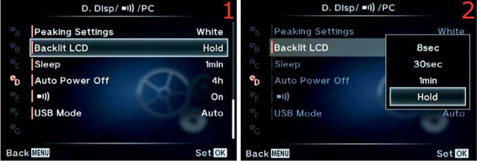
Figure 6.47: Choosing a Backlit LCD time-out period for dimming the monitor
Use the following steps to modify the Backlit LCD function:
1. Select Backlit LCD from the D. Disp/[Sound]/PC menu and scroll to the right (figure 6.47, image 1).
2. Select 8sec, 30sec, 1min, or Hold from the up/down menu (figure 6.47, image 2). The factory default is Hold, which never dims the screen.
3. Press the OK button to Set the value.
Settings Recommendation: I set my camera’s Backlit LCD time-out to 8sec so I can save battery life. It is hard to make it through a full day of shooting with the EVF and monitor drawing so much power, so I am glad to have a dim function. I can undim the LCD by merely pressing the Shutter button halfway. If 8 seconds (8sec) is not enough time for you to compose and shoot with the LCD monitor, try 30sec or 1min. If you choose 1min, be aware that the Sleep function (next subsection) will likely prevent the monitor from dimming.
Sleep
The Sleep function could just as easily be called energy-saving mode. It puts the camera to sleep after a time-out period. Backlit LCD, discussed in the previous subsection, causes the monitor to dim significantly after a set period. The Sleep function takes it a step further by turning the monitor and electronic viewfinder (EVF) off until you use a camera control.
You can choose to have the display screens go to sleep after 1, 3, or 5 minutes (1min, 3min, or 5min). After the camera has gone to sleep, it will not wake back up until you press a button or turn a dial. When you do press a button—while the camera is in energy-saving Sleep mode—the camera ignores the normal function of that button and simply wakes up.
If you accidentally forget to turn the camera off and leave it in Sleep mode, it will turn itself off after a set period of time, which you can control with the Auto Power Off function (discussed in the next subsection).
Let’s consider how to choose a Sleep mode time-out.
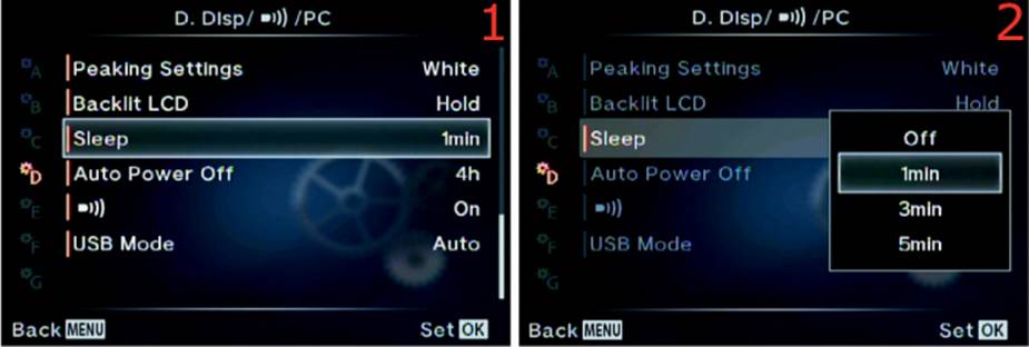
Figure 6.48: Choosing a Sleep time delay
Use the following steps to modify the Sleep function:
1. Select Sleep from the D. Disp/[Sound]/PC menu and scroll to the right (figure 6.48, image 1).
2. Select 1min, 3min, or 5min from the up/down menu (figure 6.48, image 2). You can also choose Off. The factory default is 1min.
3. Press the OK button to Set the value.
Settings Recommendation: I leave my camera set to 1min. The battery draw is so high for the bright screens that I want my camera to go to sleep quickly when I’m not using it.
I have found that the camera will go to sleep even when I am carrying it on a strap around my neck. At first I thought the sensor on the viewfinder eyepiece, which tells the camera to switch to the EVF, might sense my clothing and not let the camera go to sleep, but that’s not the case. If you do not use a physical camera control within the time-out period you chose in the Sleep function, the camera will shut down the display screens and go into energy-saving mode.
When the camera is in Sleep mode, it starts the countdown to Auto Power Off, which will shut down the camera completely. We will consider Auto Power Off next.
Auto Power Off
Auto Power Off shuts down your camera if you do not use it for a certain period of time. You can set the camera to automatically shut off after 5 minutes (5min), 30 minutes (30min), 1 hour (1h), or 4 hours (4h).
The camera shuts down after the time-out period you select, even though the On/Off switch is set to On. If the camera has shut down with the On/Off switch set to On, you can to turn the switch Off and back On again to power up the camera. It will not come back on when you use any other camera control, unlike the Backlit LCD and Sleep functions.
Let’s examine how to choose an Auto Power Off time-out period.
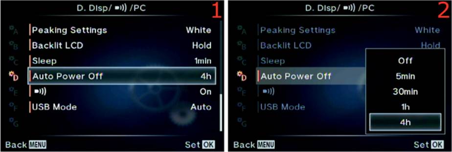
Figure 6.49: Choosing an Auto Power Off time delay
Use the following steps to modify the Auto Power Off function:
1. Select Auto Power Off from the D. Disp/[Sound]/PC menu and scroll to the right (figure 6.49, image 1).
2. Select Off, 5min, 30min, 1h, or 4h from the up/down menu (figure 6.49, image 2). The factory default is 4h.
3. Press the OK button to Set the value.
Settings Recommendation: The 1h setting seems about right to me. If I haven’t used my camera in an hour, I probably won’t use it for a while, and I can easily switch it off and back on when I need to take more pictures. The 4h setting will work too; however, that seems like a long time to have the camera partially active. Even though the display screens are asleep while the camera is in energy-saving mode—if the Sleep function is configured correctly—the other parts of the camera are still using more power than when the camera is off.
[Speaker]
The [Speaker] function controls the beep sound you hear when you are taking a picture and the camera successfully autofocuses. The beep can be useful at times—it is a reassurance that AF is working. However, in certain environments the beep simply calls attention to the fact that you are taking pictures.
If you are shooting a wedding, do you really want the camera to beep every time it autofocuses? Or if you are sneaking up on a grizzly bear, shouldn’t your camera cooperate by preventing you from becoming dinner?
The beep sound can be turned off (thankfully). Let’s see how.
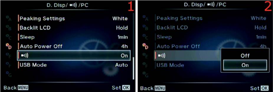
Figure 6.50: Enabling or disabling the beep sound
Use the following steps to modify the [Speaker] (beep sound) function:
1. Select [Speaker] from the D. Disp/[Sound]/PC menu and scroll to the right (figure 6.50, image 1).
2. Select Off or On from the up/down menu (figure 6.50, image 2). The factory default is On.
3. Press the OK button to Set the value.
Settings Recommendation: The first function I modify when I get a new camera is the one that disables beep sounds. I have learned over the years that some subjects don’t like the sound. If you are a new photographer you may want to hear the sound for a while as a reassurance that autofocus has completed. Just be careful around large animals!
USB Mode
The E-M1 offers several industry standard modes for connecting the camera to external devices through the factory-supplied USB cable. The camera has a USB connector under the bottom rubber flap to the left of the LCD monitor. You can use the cable to transfer image and video files to your computer and to print pictures on a PictBridge-compatible printer.
Let’s consider the three protocols the camera supports for connection to external devices, plus its Auto detect mode:
• Auto: This mode lets the camera decide which type of connection to use, depending on the type of device you plug your camera in to. If you get no results with the Auto setting, test the other modes to see what works with the external device.
• Storage: This mode refers to the mass storage class (MSC) specification, which is an industry standard for connecting a device containing storage memory to a computer. The MSC protocol is used by your camera, external hard drives, and card readers. You can use the Storage mode to transfer image and video files to your computer through Olympus Viewer software or other software. When you use Storage mode the camera will show up in your computer’s file browser as a local hard drive. You can then access the DCIM folder on the memory card directly, then manually copy images and videos to and from the camera. When you plug the camera in to a USB port on your computer using the factory-supplied USB cable, your computer should react by offering to load the Olympus Viewer software if you have installed it. Olympus Viewer (version 3 in late 2014) will help you transfer images to your computer and allow you to enhance them (e.g., convert RAW files to JPEG). This is also the mode you must use when you are updating the firmware on your camera with Olympus Digital Camera Updater software.
• MTP: This mode refers to media transfer protocol (MTP), which was created by Microsoft as an extended set of tools for synchronizing pictures, videos, sound files, and songs from devices to a computer with Windows installed. It offers content management tools for creating playlists, autosyncing, and transferring DRM-protected (licensed) media. This mode does not seem to work well with Olympus Viewer 3 software, although it may work with other software. Olympus Digital Camera Updater software (version 1.03) does not recognize the camera when you are using this mode. It generates the following error: Unable to use this function on this camera. Therefore, you may want to use Storage mode, instead of MTP mode, when you transfer files. You definitely should use it when you update the camera’s firmware. There are probably other types of control/transfer software that will work with MTP mode. It is good to know the camera has it if you need it.
• Print: This refers to PictBridge printing mode, which allows you to connect your camera directly to a PictBridge-compatible printer, without a computer, and print some or all of the images on the memory card. When you plug the camera into a PictBridge-compatible printer, you will see a Print Mode Select menu on the camera monitor, which allows you to use the following menu items:
Print Mode Select menu
• Print: Print individual images.
• All Print: Print all images on the memory card.
• Multi Print: Print multiple copies of one image in separate frames on one sheet of paper.
• All Index: Print an index of small thumbnails of all the pictures on the card.
• Print Order: Print a Print Order that was previously created and stored on the memory card (see page 262 for information about creating Print Orders, which can be used in any printer that will accept an SD card and can read a DPOF Print Order format).
Since this mode requires interfacing directly with various types of PictBridge printers, it is beyond the scope of this book. However, a downloadable document called PictBridge Printing with Your E-M1 will be available at the downloadable resources website (http://www.rockynook.com/OlympusEM1) in the first quarter of 2015. It fully describes the complex process of PictBridge printing while your camera is connected to an Epson inkjet printer.
In the meantime, there is a brief explanation of PictBridge printing on pages 112–115 of the E-M1 user’s manual.
Now let’s consider how to select one of the USB modes.
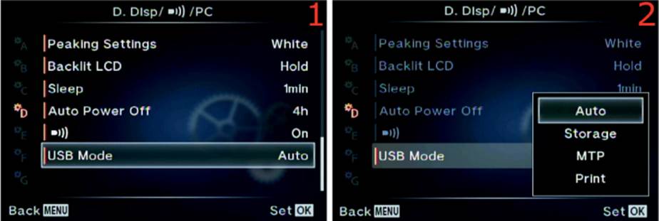
Figure 6.51: Selecting a USB mode for image or video transfer and still image direct printing
Use the following steps to select a USB Mode for image and video transfer and picture printing:
1. Select USB Mode from the D. Disp/[Sound]/PC menu and scroll to the right (figure 6.51, image 1).
2. Select Auto, Storage, MTP, or Print from the up/down menu (figure 6.51, image 2). Refer to the Print Mode Select menu list to decide which mode to use.
3. Press the OK button to Set the value.
Settings Recommendation: I leave my camera set to Storage so I can transfer images and videos through my USB cable. I also update my camera’s firmware whenever an update is available, which also requires the Storage mode. I rarely do any sort of PictBridge printing because I like to use a professional lab for my commercial work and a local lab for my snapshots.
Custom Menu E. Exp/[Meter]/ISO
The E. Exp/[Meter]/ISO menu is primarily composed of functions that directly affect how the image is exposed. We will start examining the functions by taking a look at the opening menu for the E. Exp/[Meter]/ISO functions in figure 6.52.
To enter the menu, you must select E. Exp/[Meter]/ISO from the Custom Menu and scroll to the right. There are 14 functions inside the E. Exp/[Meter]/ISO menu. Let’s consider each of them in detail.

Figure 6.52: The opening menu selection for the E. Exp/[Meter]/ISO functions
EV Step
Use this function to choose an exposure value (EV) increment when you select a shutter speed, aperture, exposure compensation, and bracketing exposure value. As photographers, we think of exposure in stops. A 1-stop increment doubles or halves the amount of light the camera can use for making a picture, depending on whether you are letting in more light (double) or less light (half). A single stop is equivalent to 1 EV step.
The camera allows you to use finer increments than 1 EV step when you make exposure adjustments. You can select from 1/3 EV step, 1/2 EV step, or 1 EV step. The following three EV step lists show a partial breakdown of EV steps that are available as you adjust an exposure:
1/3 EV step
• Shutter: 1/100, 1/125, 1/160, 1/200, 1/250, 1/320, etc.
• Aperture: f/5.6, f/6.3, f/7.1, f/8.0, f/9.0, f/10, etc.
• Compensation/bracketing: 0.0, 0.3, 0.7, 1.0, 1.3, 1.7, 2.0, 2.3, 2.7, 3.0, etc.
1/2 EV step
• Shutter: 1/90, 1/125, 1/180, 1/250, 1/350, 1/500, etc.
• Aperture: f/5.6, f/6.7, f/8.0, f/9.5, f/11, f/13, etc.
• Compensation/bracketing: 0.0, 0.5, 1.0, 1.5, 2.0, 2.5, 3.0, etc.
1 EV step (1 stop)
• Shutter: 1/60, 1/125, 1/250, 1/500, 1/1000, 1/2000, etc.
• Aperture: f/2.8, f/4.0, f/5.6, f/8.0, f/11, f/16, f/22, etc.
• Compensation/bracketing: 0.0, 1.0, 2.0, 3.0, 4.0, 5.0 (note that 5.0 is the maximum)
The fineness of your exposure control will vary depending on how you set this function; that is, which EV step increment you choose (1/3EV, 1/2EV, or 1EV step). Let’s examine how to select one of the three EV increment values.
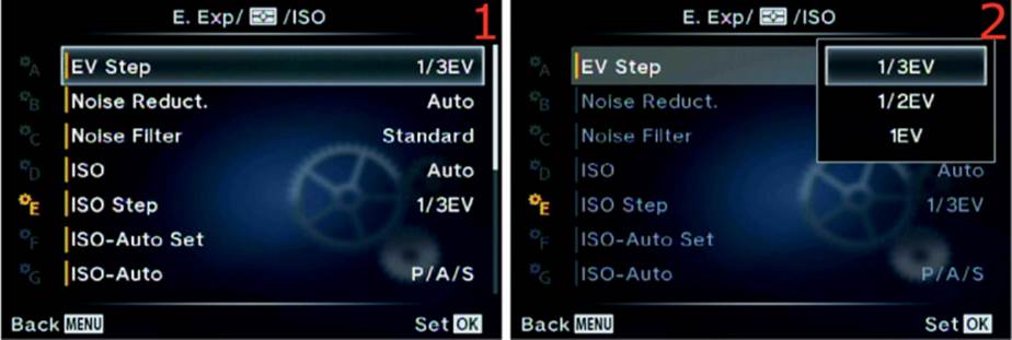
Figure 6.53: Choosing an EV step value for exposure control
Use the following steps to select an EV increment value for camera exposure settings:
1. Select EV Step from the E. Exp/[Meter]/ISO menu and scroll to the right (figure 6.53, image 1).
2. Select 1/3EV, 1/2EV, or 1EV from the menu that appears (figure 6.53, image 2). Refer to the three previous EV step lists to help you decide which EV step is most appropriate for the type of pictures you are creating.
3. Press the OK button to Set the value.
Settings Recommendation: I leave my camera set to 1/3 EV step (1/3EV). Most photographers do the same. While using camera-supplied tools, such as the Live Histogram, it is best to have fine control over the exposure value. With 1/3 EV step you can adjust the exposure in fine increments. If you do not need such fine control, experiment with the other two selections.
Noise Reduct.
During a long exposure the sensor may exhibit more noise than is acceptable. The sensor gets warm after several seconds of use. This warming effect produces amp noise, which causes warmer sections of the sensor to have more noise than cooler sections.
This noise resembles a fog-like brightening around the edges of the frame. Also, there can be bright spots with various colors at numerous places in the image. This special type of long-exposure noise degrades the image in a different way than the noise from high-ISO sensitivity, which presents as grainy ugliness in darker areas of the image.
Using Noise Reduct.
When you enable Noise Reduct. (long-exposure noise reduction) and an exposure is longer than about 2.5 seconds, the camera will take two pictures with approximately the same exposure time. The first picture is normal. The second picture is a black-frame subtraction exposure, which is exposed for about the same duration as the first picture with the shutter closed.
The camera examines the noise in the black-frame subtraction exposure and subtracts it from the first image. Since long-exposure noise (bright spots in random places and fog at the edges) is different from high-ISO noise (grainy degradation in darker areas), the high-ISO Noise Filter function (next subsection) would not work well with long-exposure noise. Therefore, for those of us who shoot long exposures regularly, the Noise Reduct. function is very important.
The main drawback to long-exposure noise reduction is that the total exposure time can be as much as doubled—a 5-second exposure becomes a 10-second exposure—because two exposures are made. The black-frame subtraction exposure is not written to the memory card; therefore, when the noise reduction process is done you will have only one image with much less noise.
While the black-frame subtraction exposure is being processed, the orange memory card access symbol will blink in the top-left corner of any active displays. While the symbol is flashing, you cannot use the camera. If you turn the camera off during a long-exposure noise reduction session, the image will be lost.
There are three selections available within the Noise Reduct. function:
• Auto: The camera chooses whether or not to use long-exposure noise reduction. It will usually kick in at a shutter speed of about 2.5 seconds or with a small aperture that makes the shutter stay open that long.
• On: Long-exposure noise reduction is active on all pictures taken at all shutter speeds, not just long exposures.
• Off: No long-exposure noise reduction is performed on any image.
Now let’s see how to configure your camera to use Noise Reduct.
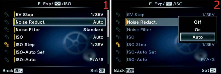
Figure 6.54: Selecting a Noise Reduct. setting for long exposures
Use the following steps to select a long-exposure Noise Reduct. setting:
1. Select Noise Reduct. from the E. Exp/[Meter]/ISO menu and scroll to the right (figure 6.54, image 1).
2. Select Off, On, or Auto from the menu that appears (figure 6.54, image 2).
3. Press the OK button to Set the value.
Note: Noise Reduct. may also kick in when ambient temperatures are high, such as on a hot summer day. The sensor can get quite warm when the camera is in the sun absorbing heat.
If you are shooting in [Sequential] H or [Sequential] L modes, firing off rapid bursts of images, the camera is smart enough to turn off Noise Reduct. for the image bursts. There is no need to slow the bursts down, even on a hot day.
Settings Recommendation: The factory default setting is Auto, and I’ve found that it works well for me. The camera consistently kicks in long-exposure noise reduction at a shutter speed of about 2.5 seconds and results in nicer-looking long exposures than without the setting enabled. When the picture is taken at a shutter speed faster than 2.5 seconds in Auto, the Noise Reduct. function is not used. Auto may be the best choice for most photographers because many exposures are shorter than 2.5 seconds, and Noise Reduct. will be used only when it is needed.
I don’t need Noise Reduct. all the time, so I don’t use the On setting, nor do I want to completely shut it Off. Make some long-exposure shots with and without Noise Reduct. enabled and see which works best for you.
Noise Filter
The Noise Filter function is designed to remove high-ISO noise from your images by blurring the image slightly. The blurring action tends to blend the grainy noise detail into the darker background, lessening the degrading effect of noise. The camera then resharpens the image to bring out more edge detail.
There are four settings: Off, Low, Standard, and High. The camera defaults to Standard. Each setting blurs the image more, making noise less apparent (and removing image detail), as you move from Low to High.
In figure 6.55A you can see the progression of the Noise Filter as it is increased in power from Off to High. The pictures were taken at ISO 3200. The four cutouts, as indicated by the red rectangle in the small center picture, are magnified by about 10x. The camera does an excellent job of noise control for its small sensor.
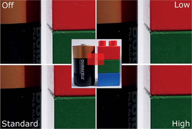
Figure 6.55A: Four settings for the high-ISO Noise Filter
Now let’s examine how to choose a Noise Filter setting.
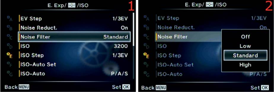
Figure 6.55B: Choosing a high-ISO Noise Filter setting
Use the following steps to select a high-ISO Noise Filter setting:
1. Select Noise Filter from the E. Exp/[Meter]/ISO menu and scroll to the right (figure 6.55B, image 1).
2. Select Off, Low, Standard, or High from the menu that appears (figure 6.55B, image 2). Refer to the four Noise Filter settings in figure 6.55A to help you choose the setting you want to use.
3. Press the OK button to Set the value.
Settings Recommendation: While I was shooting various indoor events (e.g., high school graduations, weddings, baptisms) with my E-M1, I had to shoot in rather low light. I used ISO 1600 and got excellent results as long as I kept my Live Histogram pegged on the bright side (exposed for the highlights). I found that the Standard high-ISO Noise Filter, which is the default, worked well for me. It seems to balance noise removal blurring and resharpening.
With a smaller sensor, such as the E-M1 Micro Four Thirds sensor, it is critical that exposures are correct in low light. Brightening a high-ISO image will often lead to objectionable noise.
Judicious use of the high-ISO Noise Filter will help protect you from excessive noise in images where the light is not ideal.
ISO
The E-M1 has an ISO range from Low (ISO 100) to ISO 25600. ISO 200 is the base ISO and is the factory default. You can choose an ISO sensitivity setting from this Custom Menu, along with several other ISO adjustments, in the next three Custom Menu items (see the upcoming subsections).
The ISO sensitivity choices you will see on the menu, shown in figure 6.56, image 2, are in 1/3 EV steps, but they can be changed to 1 EV steps in the ISO Step value function considered in the next subsection. Let’s see how to select an ISO value.

Figure 6.56: Selecting an ISO value from the Custom Menu
Use the following steps to choose an ISO sensitivity setting:
1. Select ISO from the E. Exp/[Meter]/ISO menu and scroll to the right (figure 6.56, image 1).
2. Select an ISO sensitivity value from the menu that appears (figure 6.56, image 2).
3. Press the OK button to Set the value.
Settings Recommendation: I use ISO 200 for standard, noncommercial handheld shooting. When I have my camera on a tripod for maximum sharpness in landscapes, I often use ISO 100. My personal maximum for the highest-quality images is around ISO 1600, and ISO 3200 is the highest ISO I use for standard-quality images.
Experiment with various ISO settings. Make sure the exposure of each image is correct so you won’t have to brighten it during post-processing and increase the noise. The smaller sensor in the E-M1 demands a good exposure for the best results. However, your tolerance for noise may be higher than mine.
ISO Step
The previous ISO function presented ISO values in 1/3 EV steps. It and all other camera menus that allow you to change the ISO use the ISO Step function as the basis for the ISO increments on the camera displays. You can choose from either 1/3 EV step or 1 EV step.
Here is a partial list of ISO increments for both ISO Step values: 1/3 EV step: Auto, Low (100), 200, 250, 320, 400, 500, 640, 800, etc. 1 EV step: Auto, Low (100), 200, 400, 800, 1600, 3200, 6400, etc.
If you want to use smaller increments, leave this setting at the factory default of 1/3 EV. If you want to select ISO values in 1 EV step (1 stop) increments, you can change it here. Let’s see how.
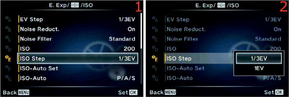
Figure 6.57: Choosing an ISO Step increment
Use the following steps to choose an ISO sensitivity setting:
1. Select ISO Step from the E. Exp/[Meter]/ISO menu and scroll to the right (figure 6.57, image 1).
2. Select 1/3EV or 1EV from the menu that appears (figure 6.57, image 2).
3. Press the OK button to Set the value.
Settings Recommendation: I use the 1/3EV ISO Step value because I want fine increments of ISO values to choose from. If you prefer coarser 1-stop ISO sensitivity increments, choose 1EV instead.
ISO-Auto Set
When you set the ISO sensitivity to Auto, the camera will choose the best ISO to use for the current subject, without concern for image noise from high ISO values.
ISO-Auto Set is used to control the upper and lower range of your camera’s ISO sensitivity. In effect, you are telling the camera it can use any ISO value within a certain range, but it cannot exceed that range with higher or lower ISO values. The total available ISO range is from ISO 200 to ISO 25600.
There are two settings in the ISO-Auto Set function:
• High Limit: The High Limit setting controls the maximum ISO value that you will allow the camera to use in difficult lighting conditions. The camera is free to use any ISO value up to the High Limit setting. If you choose ISO 1600 as the High Limit, the camera can use any ISO from the lower Default limit (next setting) up to 1600, but it cannot exceed 1600.
• Default: The Default setting serves two purposes. First, it is the default ISO value that the camera will use when there is sufficient light to drop the ISO to the lowest setting. Second, it is the lowest ISO value the camera is allowed to use when the light gets brighter. If you select ISO 400 as the Default value, the camera is free to use any ISO from 400 up to the High Limit (previous setting).
Look at the Default and High Limit as a floor and a ceiling. When you use Auto ISO the camera cannot drop the ISO below the Default floor or raise it above the High Limit ceiling. These values give you excellent control of the Auto ISO boundaries.
Let’s examine how to choose an ISO value for the two settings.
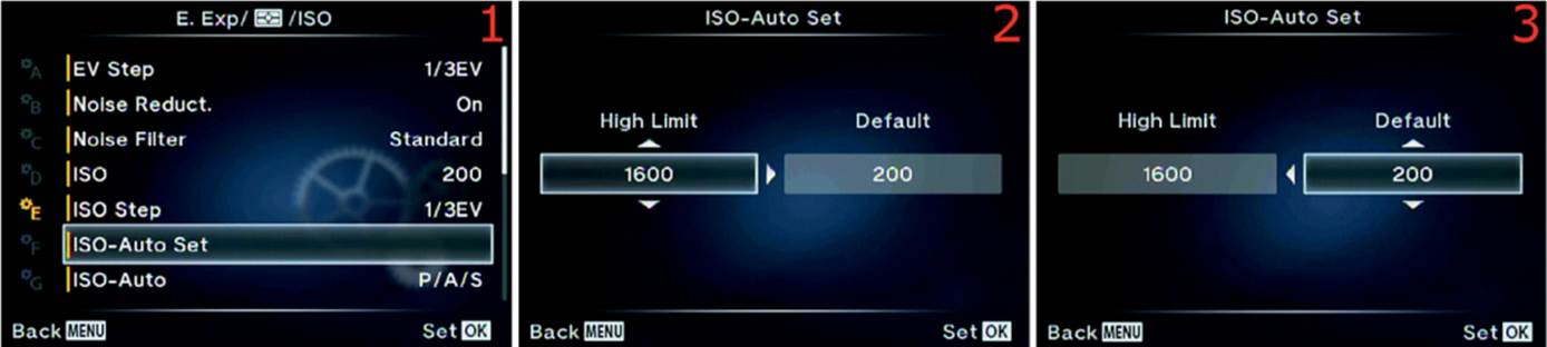
Figure 6.58: Choosing a High Limit and a Default value for Auto ISO
Use the following steps to choose an ISO-Auto Set value for the High Limit and Default settings:
1. Select ISO-Auto Set from the E. Exp/[Meter]/ISO menu and scroll to the right (figure 6.58, image 1).
2. Choose an ISO value from the High Limit up/down menu (figure 6.58, image 2). The available ISO values range from ISO 200 to ISO 25600. I chose a High Limit of ISO 1600.
3. Choose an ISO value from the Default up/down menu (figure 6.58, image 3). The available ISO values range from ISO 200 to ISO 25600. I chose a Default of ISO 200. You cannot select the Low (ISO 100) value.
4. Press the OK button to Set the two values.
Settings Recommendation: I use ISO 1600 as my High Limit. I don’t like the noise that results with higher ISO values, especially if I don’t nail the exposure. I use ISO 200 to ISO 400 as the lower Default value, depending on the ambient light and whether I am using flash. When I use flash indoors, I often use ISO 400 as Default and ISO 1600 as High Limit.
ISO-Auto
Use the ISO-Auto function to control which modes on the Mode Dial allow the use of automatic ISO (called Auto on the ISO selection menus; I will use Auto ISO in this book.) The factory default is for Auto ISO to be available only in Program (P), Aperture-priority (A), and Shutter-priority (S) modes. Normally Auto ISO is not available when you are using Manual (M) mode, so the selection is grayed out on the menu.
However, the camera allows you to use Auto ISO in Manual (M) mode. There are two settings in the ISO-Auto function:
• P/A/S: When this mode is selected the camera allows the Auto ISO function to be accessible on the menus only when you are using Program (P), Aperture-priority (A), and Shutter-priority (S) modes. Auto ISO will be grayed out and unavailable on all ISO selection menus when you are using Manual (M) mode.
• All: When you select this mode the camera will offer Auto ISO on all ISO selection menus when you use P, A, S, or M mode on the Mode Dial. Note that Manual (M) mode is included.
Let’s see how to select a setting.
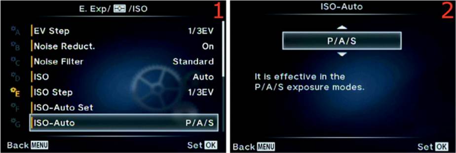
Figure 6.59: Choosing which Mode Dial setting allows Auto ISO
Use the following steps to choose an ISO-Auto setting:
1. Select ISO-Auto from the E. Exp/[Meter]/ISO menu and scroll to the right (figure 6.59, image 1).
2. Select either P/A/S or All from the up/down menu (figure 6.59, image 2).
3. Press the OK button to Set the value.
Settings Recommendation: The All setting makes sense for the types of photography I do (events and nature). I use Auto ISO only when I must get the shot at all costs or when I am shooting just for fun. However, if I wanted to shoot with Auto ISO in Manual (M) mode, I wouldn’t want a limitation imposed upon me.
If you do not think you will use Auto ISO in M mode, simply leave this function set to the factory default of P/A/S.
Metering
The E-M1 has five meter types, which gives you great flexibility in how you expose your images. Using the meter styles built in to the camera along with the Live Histogram will allow you to take some of the best-exposed images you’ve ever created.
Let’s look more closely at the five types of light meters built in to the camera and discuss their differences:
|
|
[Digital ESP Metering]: ESP stands for electrosensitive pattern. The camera meters the image in a grid of 324 metered areas. It examines each of the 324 areas and uses complex mathematical computations to arrive at an excellent exposure most of the time. This metering mode works best for portraits when Face Priority is enabled. |
|
|
[Center-Weighted Averaging Metering]: The camera averages the light between the subject and the background. It places more emphasis on the center area of the screen (large fuzzy red circle in the accompanying image) with less emphasis on parts of the scene that are farther away from the center. This mode is provided for those of us who learned to use a center-weighted meter and prefer to use that metering method. You will see a medium-sized circle in the middle of the monitor. The circle does not represent the actual size of the averaging meter’s most important metering area; it shows just the center. |
|
|
[Spot Metering]: The camera uses a small circle in the center of the frame for metering. This circle is equivalent to 2 percent of the frame and is roughly represented by the red dot in the accompanying figure. All metering takes place in this 2 percent area. Therefore, you must place this nonmoveable spot on the area of the subject that you want to correctly meter by moving the camera then using autoexposure lock (AEL/AFL button) to lock the exposure while you recompose the image (see the next subsection,AEL Metering). Or you can take multiple readings of different areas of the scene, determine the total light range, and set the exposure manually. |
|
|
[Spot Metering—Highlight (HI)]: This type of metering is similar to [Spot Metering] in that the camera uses a small circle in the center of the frame to meter. This circle is equivalent to 2 percent of the frame and is roughly represented by the red dot in the accompanying figure. This metering mode is different because the camera tries to make white areas (highlights) stay white by increasing the exposure beyond a [Spot Metering] reading to give a bright, high-key look to the image. |
|
|
[Spot Metering—Shadow (SH)]: This type of metering is similar to [Spot Metering] in that the camera uses a small circle in the center of the frame to meter. This circle is equivalent to 2 percent of the frame and is roughly represented by the red dot in the accompanying figure. This metering mode is different because the camera tries to make dark areas (shadows) stay dark by decreasing the exposure below a [Spot Metering] reading to give a low-key look to the image. |
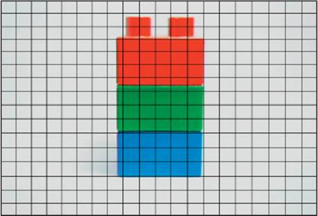
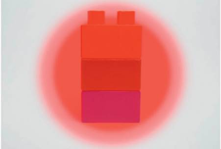
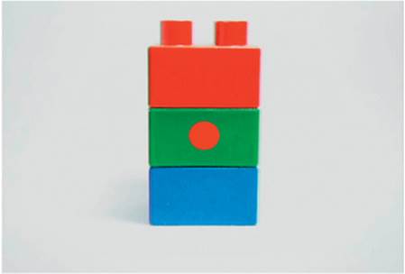

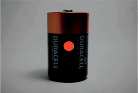
Now let’s examine how to select one of the metering types.
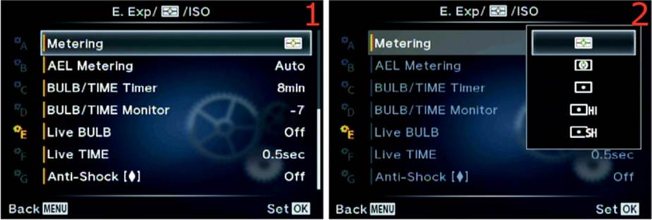
Figure 6.60F: Choosing a light meter type
Use the following steps to choose a Metering type:
1. Select Metering from the E. Exp/[Meter]/ISO menu and scroll to the right (figure 6.60F, image 1).
2. Select one of the five meter types shown in the menu (figure 6.60F, image 2).
3. Press the OK button to Set the value.
Settings Recommendation: I usually use [Digital ESP Metering]. I like the way it evaluates all areas of the screen and arrives at an excellent exposure. However, I have found that it is best to use Face Priority along with this meter type to have the best exposure for portraiture.
There is a meter type for each of us: the [Center-Weighted Averaging Meter] is good for old-timers who like this traditional meter style. The three types of [Spot Metering] allow extremely accurate metering of specific areas of a subject for those who understand how to use a spot meter. The highlight and shadow meters add icing to the cake.
I suggest experimenting with all these meter types until you are familiar with them.
AEL Metering
When you press the AEL/AFL button with the camera configured for autoexposure lock, the camera makes a meter reading then locks the exposure until you release the AEL/AFL button. Olympus has provided a means for you to choose which type of meter your camera will use to make the exposure reading that will be locked.
There are five AEL Metering modes:
• Auto: When you press the AEL/AFL button, the camera uses whichever metering mode you selected in the Metering subsection. This is the factory default setting, and it is apparently the only way to access [Digital ESP Metering] for autoexposure lock.
• [Center-Weighted Averaging Metering]: When you press the AEL/AFL button, the camera switches to [Center-Weighted Averaging Metering], as described in the Metering subsection.
• [Spot Metering]: When you press the AEL/AFL button, the camera switches to [Spot Metering], as described in the Metering subsection.
• [Spot Metering—Highlight (HI)]: When you press the AEL/AFL button, the camera switches to [Spot Metering—Highlight (HI)], as described in the Metering subsection.
• [Spot Metering—Shadow (SH)]: When you press the AEL/AFL button, the camera switches to [Spot Metering—Shadow (SH)], as described in the Metering subsection.
Let’s see how to select one of the five metering types for autoexposure lock.
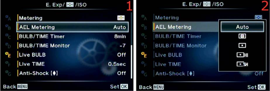
Figure 6.61: Choosing a metering mode for autoexposure lock
Use the following steps to choose a Metering type when you press the AEL/AFL button:
1. Select AEL Metering from the E. Exp/[Meter]/ISO menu and scroll to the right (figure 6.61, image 1).
2. Select one of the five meter types shown in the menu (figure 6.61, image 2).
3. Press the OK button to Set the value.
Settings Recommendation: The Auto mode seems to be the most reasonable setting for me. I normally have the best light meter type already selected before I use autoexposure lock.
However, maybe you are metering a beautiful sunset and decide to use autoexposure lock to meter a bright orange cloud. You might want to use [Spot Metering]. If you already had the AEL Metering function set to [Spot Metering], you would be ready to shoot. You could meter the bright cloud, recompose, take the shot, then continue shooting with [Digital ESP Metering] for more images of other subjects. In cases like this it may be wise to separate the Metering types when you use normal metering and after pressing the AEL/AFL button.
BULB/TIME Timer
When you set your camera to Manual (M) mode on the Mode Dial and turn the shutter speed to its lowest setting with the Rear Dial, you will find specific shutter speed settings called BULB (or LIVE BULB) and LIVE TIME. (Note: Do not confuse these camera shutter speed settings with the Live BULB and Live TIME function names in upcoming sections of this chapter). The BULB, LIVE BULB, and LIVE TIME shutter speed settings allow you to make long exposures from 1 to 30 minutes in length.
The BULB/TIME Timer function allows you to control the maximum time for the long exposures. You can select from a range of 1min (1 minute) to 30min (30 minutes). When you use the BULB or LIVE BULB shutter speed setting you have to manually hold the shutter open by pressing the Shutter button or using a locking electronic shutter-release cable. We will discuss the BULB and LIVE BULB shutter speeds in more detail in upcoming subsections. When you use the LIVE TIME shutter speed setting, the camera holds the shutter open for you.
Let’s examine how to select one of the BULB/TIME Timer settings.
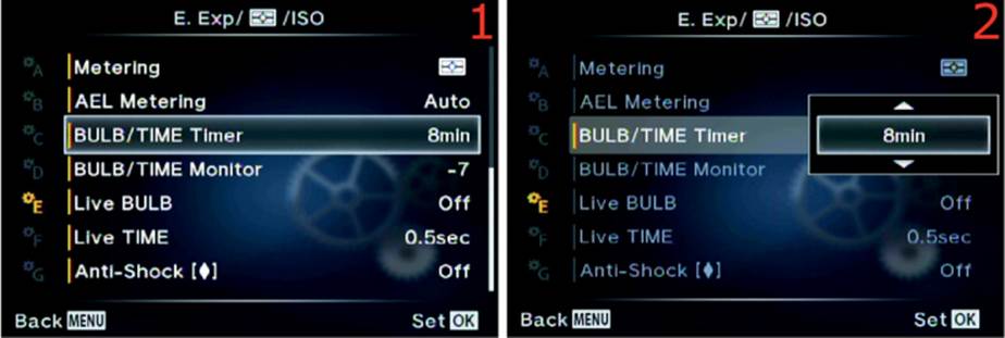
Figure 6.62: Choosing a time-out setting for the BULB/TIME Timer function
Use the following steps to choose a time-out or maximum time to have the shutter open when you use the BULB, LIVE BULB, or LIVE TIME shutter speed settings for long exposures:
1. Select BULB/TIME Timer from the E. Exp/[Meter]/ISO menu and scroll to the right (figure 6.62, image 1).
2. Select one of the eight time-out values from the up/down menu. Your choices range from 1min to 30min (figure 6.62, image 2).
3. Press the OK button to Set the value.
Note: If you are using the Noise Reduct. function (see the Noise Reduct. subsection), the camera will use long-exposure noise reduction for each of your BULB, LIVE BULB, or LIVE TIME exposures, effectively doubling the time of the exposure. Therefore, a 1-minute exposure will be doubled to 2 minutes, and an 8-minute exposure will be doubled to 16 minutes. This is due to the black-frame subtraction method the camera uses to reduce noise in long exposures. You can disable Noise Reduct. if you do not want the shutter to be open for double the exposure time, but your images may have fog and bright spots because of amp noise and hot pixels.
Settings Recommendation: You will have to decide how long your exposure needs to be for your purposes. For LIVE BULB and LIVE TIME shutter speed exposures, the camera will show you the light buildup of the actual exposure on the Live view display screen so you can see how the long exposure is progressing over time. The screen can update itself—showing you the progress of the exposure—up to 24 times during each exposure. The number of times the live exposure preview updates is governed by the sensitivity of the ISO setting. The amount of time between each screen update (from 0.5 to 60 seconds) is controlled by the upcoming Live BULB and Live TIME functions. For BULB shutter speed exposures, you will not see the light buildup on the Live view display screen. You will have to wait until you release the shutter and the Noise Reduct. function has finished removing long-exposure noise before the final image will appear on the screen.
BULB/TIME Monitor
You will normally use the BULB, LIVE BULB, and LIVE TIME shutter speeds to take long exposures in the dark. Therefore, you may want the monitor to be very dim to preserve your night vision.
On the other hand, you may be shooting a one- or two-minute daylight exposure with a neutral-density (ND) filter to hold back the brightness of the exposure and allow a long exposure in normal light. In that case you may want a normal or extra-bright monitor.
The camera allows you to change the brightness of the monitor by using the BULB/TIME Monitor function. You can select from –7 to +7, or 14 steps of brightness. The factory default is –7 for a very dim monitor. You will see the monitor dim immediately when you select the BULB, LIVE BULB, or LIVE TIME shutter speeds.
Let’s examine how to select the monitor brightness for long exposures.
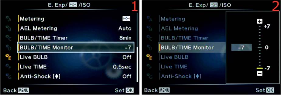
Figure 6.63: Choosing a monitor brightness level for BULB, LIVE BULB, and LIVE TIME
Use the following steps to choose a monitor brightness level when you use the BULB, LIVE BULB, or LIVE TIME shutter speeds for long exposures:
1. Select BULB/TIME Monitor from the E. Exp/[Meter]/ISO menu and scroll to the right (figure 6.63, image 1).
2. Use the Arrow pad up or down keys to choose one of the 14 brightness levels from –7 to +7 (figure 6.63, image 2). The factory default is –7 (very dim).
3. Press the OK button to Set the value.
Settings Recommendation: I do most of my long exposure shooting at night, so I leave this value set to –7. However, if you like to do daytime long exposures with a neutral-density filter, you will want your monitor to be bright. If you select the BULB, LIVE BULB, or LIVE TIME shutter speeds during the day, with this setting at –7, the monitor will be too dim to see in normal daylight. Therefore, set the value in advance.
Live BULB
When you rotate the Rear Dial while using Manual (M) mode on the Mode Dial, you will find BULB, LIVE BULB, or LIVE TIME shutter speeds as the slowest shutter speed settings.
When you set the Live BULB function to Off, the camera will use the BULB shutter speed to make exposures. If you select any other setting besides Off for the Live BULB function, the camera will use the LIVE BULB shutter speed instead of the BULB shutter speed.
Note: To avoid confusion, please notice that this function is called Live BULB. It controls a shutter speed setting named LIVE BULB. Notice the differences in uppercase and lowercase notations so you will not get Live BULB (the Custom Menu function) and LIVE BULB (the shutter speed setting) confused as we discuss them. LIVE BULB and BULB work similarly when starting and ending the image exposure—notice which term is displayed on the camera screens during the exposure so you can tell the difference. Using the Live BULB function with its LIVE BULB shutter speed allows you to see a buildup of the exposure on the camera’s Live view monitor. If you use the BULB shutter speed setting, which is available only when the Live BULB function is set to Off, you will not see a buildup of exposure on the monitor. Instead, you will see the results of the exposure when the camera has closed the shutter after the exposure is complete and any long-exposure noise reduction has been completed (see the Custom Menu > E. Exposure/[Meter]/ISO > Noise Reduct. function).
When you use the BULB or LIVE BULB shutter speed settings, the camera opens the shutter (starts the exposure) when you press and hold the Shutter button all the way down or when you manually hold the shutter open with a locking electronic cable release. The exposure ends when you release the Shutter button to close the shutter.
When Live BULB (the function discussed in this section) is set to Off and you rotate the Rear Dial to the slowest shutter speed positions, BULB will be displayed instead of LIVE BULB as one of the last few shutter speed choices.
Let’s consider each of the BULB-type shutter speed settings.
BULB Shutter Speed
When this setting is selected the word BULB will be displayed in the shutter speed position of the monitor or viewfinder (figure 6.64A, image 1).
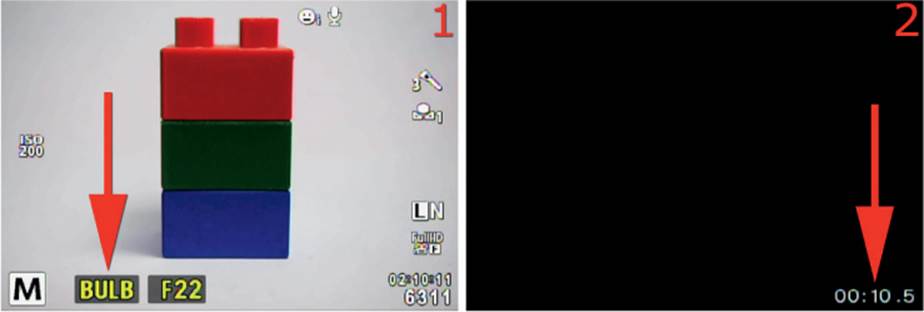
Figure 6.64A: Using the BULB shutter speed setting
When you press and hold the Shutter button and start exposing a picture using BULB, the monitor turns black. It displays a countdown timer in the lower-right corner of the screen during the long exposure (figure 6.64A, image 2). The countdown timer shows how long you have held the shutter open when using the BULB shutter speed.
As soon as you release the Shutter button, the exposure ends. If the exposure was longer than about 2.5 seconds and if long-exposure noise reduction is enabled (Custom Menu > E. Exp/[Meter]/ISO > Noise Reduct.), the camera will execute a long-exposure noise reduction cycle, doubling the exposure time while removing long-exposure noise. You will see the orange card access symbol flashing in the upper-left corner of the screen during the noise reduction cycle. When it is done, the camera will display the new image on the monitor.
LIVE BULB Shutter Speed
When you use the LIVE BULB shutter speed setting, your camera makes an exposure over time and displays the live results on your camera’s current display screen (viewfinder or monitor).
Press and hold the Shutter button to start the exposure, and the camera will start updating the live exposure on the current display screen. You can see the actual image being formed on the monitor during a LIVE BULB exposure in figure 6.64B, images 2–4.
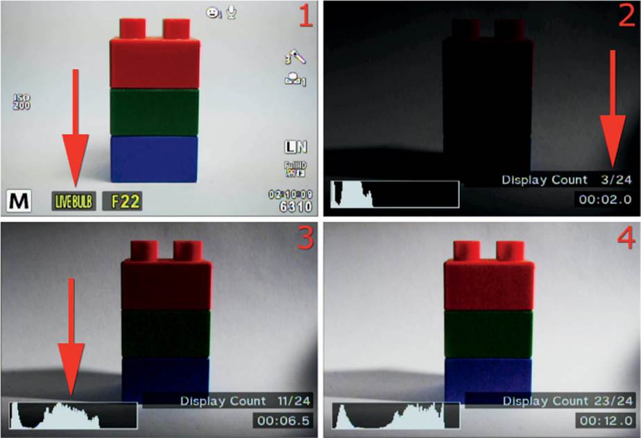
Figure 6.64B: Using the LIVE BULB shutter speed setting
When the Live BULB function is set to any value besides Off, the LIVE BULB shutter speed selection displays on the bottom left of the screen (figure 6.64B, image 1).
Figure 6.64B, image 2, shows the location of the Display Count so you can watch how many times the live exposure update has occurred (up to 24 times maximum). Image 3 shows the Live histogram that you can use to determine when the exposure is correct. If you want a good exposure, release the Shutter button when the histogram graph approaches or touches the right side of the histogram window.
The live exposure display will update in specific increments. You can select from 0.5sec (1/2 second) to 60sec (60 seconds) for the screen update increment. We will discuss how in a moment.
During an exposure using the LIVE BULB shutter speed, the camera will update the screen approximately 9 to 24 times (how many times is controlled by the ISO sensitivity). You can use the Live BULB function to choose how often the screen updates during the long exposure for each of the 9 to 24 times (Display Count).
In other words, if you select 4sec in Live BULB, the camera will update the live exposure display every four seconds up to 24 times during the actual live exposure process. You will see the image gradually appear on the screen.
The number of times (9 to 24) the live exposure display updates is controlled by the ISO sensitivity, as shown in the following Display Count list (figure 6.64C, image 2):
• ISO LOW: Approximately 24 times
• ISO 400: Approximately 19 times
• ISO 800: Approximately 14 times
• ISO 1600: Approximately 9 times
Now let’s see how to choose a time increment for the Live BULB function.
Setting a Time Increment for the Live BULB Function
Use the Live BULB function to choose how frequently the monitor displays an updated live exposure view when you use the LIVE BULB shutter speed, or whether the camera shows no live exposure updates when you use BULB (with the Live BULB function set to Off).
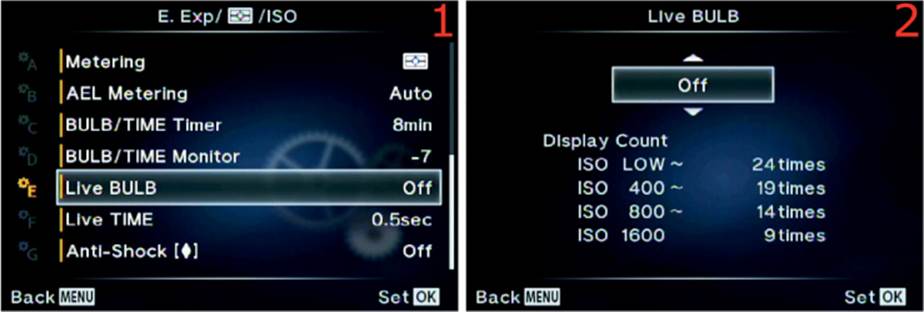
Figure 6.64C: Choose how often the live exposure view updates for LIVE BULB time exposures
Use the following steps to choose an update increment for LIVE BULB during long exposures:
1. Select Live BULB from the E. Exp/[Meter]/ISO menu and scroll to the right (figure 6.64C, image 1).
2. Choose one of the values from the up/down menu, ranging from 0.5sec to 60sec (figure 6.64C, image 2). The factory default setting is Off for BULB mode (no live exposure updates). If you want to watch the LIVE BULB mode update the screen with a live exposure, you must select how often you want it to update (e.g., 4sec) from the up/down menu. The approximate Display Count (9 times to 24 times) is shown below the up/down menu in image 2.
3. Press the OK button to Set the value.
Note: During the long exposure, if you have chosen to see the live exposure update—with Live BULB set to anything other than Off—you will see the exposure forming on the screen. If you decide the exposure is correct for your subject, either by viewing it directly or by watching the Live histogram display on the screen, you can release the Shutter button and stop the exposure at that moment.
If you have the Noise Reduct. function enabled, the camera will do a noise reduction cycle equal in time to the original exposure. It will generally double the exposure time while using black-frame subtraction to reduce noise.
Settings Recommendation: I want my camera to show a live exposure update, so I set Live BULB to something like 4sec, or maybe more for a very long exposure. The screen will be updated a maximum of 24 times, so you will need to do some math to calculate an update increment that matches the length of the planned exposure and the number of times the screen is updated.
I try to set the exposure frequency so the screen will update throughout the exposure. For instance, if I am doing a 1min exposure with the LIVE BULB shutter speed setting, at a lower ISO (24 steps) I set the Live BULB function to 2sec so the camera will update each of the 24 steps every 2 seconds. That means I will see updates on my monitor every 2 seconds until the 24 update steps have completed.
There is a nearly identical function called Live TIME (next subsection) that lets you control the updates of the screen when you use the LIVE TIME shutter speed.
Live TIME
When you rotate the Rear Dial while using Manual (M) mode on the Mode Dial, you will find that LIVE TIME is one of the slowest shutter speed settings.
Note: To avoid confusion, please notice that the function we will discuss in this section is called Live TIME. It controls the shutter speed setting named LIVE TIME. Notice the uppercase and lowercase differences so you will not get Live TIME (the Custom Menu function) and LIVE TIME (the shutter speed setting) confused as we discuss them.
When you use the LIVE TIME shutter speed setting, the camera opens the shutter (starts the exposure) when you press the Shutter button all the way down. You do not need to hold the Shutter button down when you use LIVE TIME, as you do when you use LIVE BULB (or BULB), because the camera makes the exposure for you based on the time limit that was set in the previously discussed BULB/TIME Timer function (Custom Menu > E. Exp/[Meter]/ISO > BULB/TIME Timer).
The exposure ends when the BULB/TIME Timer function’s exposure time has expired or when you press the Shutter Release button all the way down once more. You may manually stop the exposure when you think it looks right on the monitor (or on the Live histogram display) by pressing the Shutter button.
As the camera makes an exposure over time and displays the live results of that exposure on your camera’s current display screen (viewfinder or monitor), you can see the actual image being formed, as shown in figure 6.65A, images 2–4.
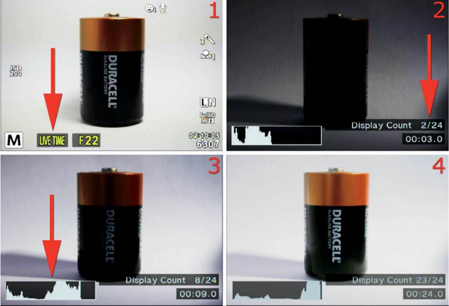
Figure 6.65A: Using the LIVE TIME shutter speed setting
The LIVE TIME shutter speed selection is displayed on the bottom left of the screen (figure 6.65A, image 1). Press the Shutter button to start the exposure, and the camera will start updating the live exposure on the current display screen.
Figure 6.65A, image 2, shows the location of the Display Count so you can watch how many times the live exposure update has occurred (up to 24 times). Image 3 shows the Live histogram that you can use to determine when the exposure is correct.
The live exposure display will update in specific increments. You can select from 0.5sec (1/2 second) to 60sec (60 seconds) for the screen update increment. We will discuss how in a moment. Figure 6.55A, image 4, shows the final exposure.
After you have selected a value besides Off for this Live TIME function, the camera will update the screen during a long exposure from approximately 9 to 24 times (how many times is controlled by the ISO sensitivity). You can use this Live TIME function to choose how often the screen updates during the long exposure for each of the 9 to 24 times.
In other words, if you select 4sec in Live TIME, the camera will update the live exposure display every 4 seconds up to 24 times maximum during the actual live exposure process. You will see the image gradually appear on the screen.
The number of times (9 to 24) the live exposure display updates is controlled by the ISO sensitivity, as shown in the following Display Count list (figure 6.65B, image 2):
• ISO LOW: Approximately 24 times
• ISO 400: Approximately 19 times
• ISO 800: Approximately 14 times
• ISO 1600: Approximately 9 times
Use the Live TIME function to choose how frequently the monitor displays an updated live exposure view when you use the LIVE TIME shutter speed setting, or whether the camera shows no live exposure updates when you use LIVE TIME (with the Live TIME function set to Off).
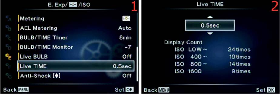
Figure 6.65B: Choose how often the live exposure view updates for LIVE TIME long exposures
Use the following steps to choose an update increment for LIVE TIME during long exposures:
1. Select Live TIME from the E. Exp/[Meter]/ISO menu and scroll to the right (figure 6.65B, image 1).
2. Choose one of the values from the up/down menu, ranging from 0.5sec to 60sec (figure 6.65B, image 2). The factory default setting is 0.5sec (1/2 second live exposure updates). If you want to see up to 24 updates per ISO setting, you must select how often you want an update to display from the up/down menu (not Off). The approximate Display Count (9 times to 24 times) is shown below the up/down menu in figure 6.65B, image 2. During the exposure, you will see the Display Count and a timer on the lower-right side of the screen while a Live histogram appears on the lower-left side of the screen.
3. Press the OK button to Set the value.
Note: During the long exposure, if you have chosen to see the live exposure update—with the Live TIME function set to anything other than Off—you will see the exposure forming on the screen. If you decide the exposure is correct for your subject, either by viewing it directly or by watching the Live histogram display on the screen, you can press the Shutter button again and stop the exposure at that moment.
If you have the Noise Reduct. function enabled, the camera will do a noise reduction cycle equal in time to the original exposure. It will generally double the exposure time while using black-frame subtraction to reduce noise.
Settings Recommendation: I want my camera to show a live exposure update, so I set Live TIME to a value, such as 2sec or 8sec, according to how long of an exposure is set in the BULB/TIME Timer function.
I try to set the exposure frequency so the screen will update all through the exposure. For instance, if I am doing an 8min exposure at a lower ISO (24 steps), I set the Live TIME function to 15sec so the camera will update one of the 24 steps every 15 seconds. That means I will see the updates on my monitor every 15 seconds until the 24 update steps have completed.
Anti-Shock [![]() ]
]
The Anti-Shock [![]() ] function is designed to cut down on sharpness-robbing vibrations that are caused by small camera movements at the time of exposure. The act of pressing the Shutter button causes camera vibrations that can produce image blurring at slow shutter speeds. If you have your camera on a tripod, you can set a delay value before the shutter fires, allowing time for vibrations to die down after you have pressed the Shutter button. You can choose delay values from the Anti-Shock [
] function is designed to cut down on sharpness-robbing vibrations that are caused by small camera movements at the time of exposure. The act of pressing the Shutter button causes camera vibrations that can produce image blurring at slow shutter speeds. If you have your camera on a tripod, you can set a delay value before the shutter fires, allowing time for vibrations to die down after you have pressed the Shutter button. You can choose delay values from the Anti-Shock [![]() ] menu from 1/8 second to 30 seconds.
] menu from 1/8 second to 30 seconds.
With firmware version 1.3 (released in March 2014), Olympus added a zero (0) selection ([![]() ]0sec) to the Anti-Shock [
]0sec) to the Anti-Shock [![]() ] menu, which enables an electronic first-curtain shutter release (instead of a mechanical release). An electronic shutter release may reduce harmonic vibrations that are caused by shutter impact at speeds less than 1/320 second. If you shoot lots of images at slow shutter speeds, the Anti-Shock [
] menu, which enables an electronic first-curtain shutter release (instead of a mechanical release). An electronic shutter release may reduce harmonic vibrations that are caused by shutter impact at speeds less than 1/320 second. If you shoot lots of images at slow shutter speeds, the Anti-Shock [![]() ] setting may produce sharper pictures.
] setting may produce sharper pictures.
Let’s examine how to choose a delay value or the [![]() ]0sec Anti-Shock [
]0sec Anti-Shock [![]() ] setting.
] setting.
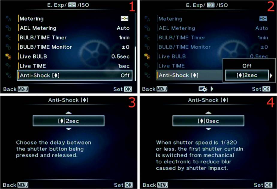
Figure 6.66: Choosing a shutter-release delay or anti-shock setting
Use the following steps to choose an Anti-Shock [![]() ] setting, which includes time delay and harmonic vibration reduction using an electronic first curtain shutter release, for slow shutter speeds:
] setting, which includes time delay and harmonic vibration reduction using an electronic first curtain shutter release, for slow shutter speeds:
1. Select Anti-Shock [![]() ] from the E. Exp/[Meter]/ISO menu and scroll to the right (figure 6.66, image 1).
] from the E. Exp/[Meter]/ISO menu and scroll to the right (figure 6.66, image 1).
2. Choose Off or [![]() ]2sec (2 seconds) from the small menu that appears (figure 6.66, image 2). At this point you can press the OK button to Set the value and skip the rest of these steps. If you need less or more than a 2 second ([
]2sec (2 seconds) from the small menu that appears (figure 6.66, image 2). At this point you can press the OK button to Set the value and skip the rest of these steps. If you need less or more than a 2 second ([![]() ]2sec) shutter delay, or if you want to choose the [
]2sec) shutter delay, or if you want to choose the [![]() ]0sec anti-harmonic vibration value, scroll to the right.
]0sec anti-harmonic vibration value, scroll to the right.
3. An up/down menu will appear with a full range of available settings (figure 6.66, image 3). Use the Arrow pad to scroll up or down, and select the Anti-Shock [![]() ] value you prefer to use. You can choose delay values ranging from [
] value you prefer to use. You can choose delay values ranging from [![]() ]1/8sec to [
]1/8sec to [![]() ]30sec, or you can choose the electronic first-curtain shutter release [
]30sec, or you can choose the electronic first-curtain shutter release [![]() ]0sec selection, to reduce harmonic vibrations at certain shutter speeds below 1/320 second (figure 6.66, image 4).
]0sec selection, to reduce harmonic vibrations at certain shutter speeds below 1/320 second (figure 6.66, image 4).
4. Press the OK button to Set your chosen value.
Settings Recommendation: If I am shooting macro shots or handheld shots with slow shutter speeds that are especially prone to being degraded by camera vibrations, I often use the electronic first-curtain shutter release [![]() ]0sec selection.
]0sec selection.
When I am shooting on a tripod I use an electronic cable release, such as the Olympus RM-UC1 Remote Cable Release, to prevent camera vibrations from damaging my shot. I also like to use the [![]() ]2sec setting to allow camera vibrations to die down before I release the shutter. Although a mirrorless camera is not as susceptible to vibrations as a DSLR, it is still wise to use a tripod and hands-off shutter release to make the sharpest possible pictures.
]2sec setting to allow camera vibrations to die down before I release the shutter. Although a mirrorless camera is not as susceptible to vibrations as a DSLR, it is still wise to use a tripod and hands-off shutter release to make the sharpest possible pictures.
Composite Settings (Live Composite)
The Live Composite function allows you to create composite images of subjects like a fireworks display (figure 6.66A). You can set up many multiple exposures on one frame, with each exposure acting independently.

Figure 6.66A: Sample composite fireworks image
The camera will automatically create a composite image as you watch the exposure timer count down. You can recompose the frame between exposures so you can capture multiple bright subjects with dark backgrounds. Figure 6.66A is 10 separate exposures that I composited.
There are two ways to configure the composite settings. You can use the Custom Menu first to configure the exposure time and then enter the Live Composite system, or you can enter the Live Composite system first then set the exposure time just before you shoot the frames you want to composite. Let’s consider both.
Setting the Composite Settings before Entering Live Composite
You can configure the exposure time for each frame before you enter the Live Composite system so your camera will be ready ahead of time. Here is how to preconfigure the composite exposure value (applies to each frame).
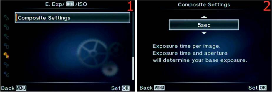
Figure 6.66B: Configuring an exposure value before entering Live Composite mode
Use the following steps to preconfigure an exposure value that will be applied to each frame of the composite image:
1. Select Composite Settings from the E. Exp/[Meter]/ISO menu and scroll to the right (figure 6.66B, image 1).
2. Choose an Exposure time per image from the Composite Settings up/down menu (figure 6.66B, image 2). Your choices in the up/down menu range from 1/2 second (1/2sec) to 60 seconds (60sec). Choose the time you want to use for each exposure in the composite series.
3. Press the OK button to Set your chosen value.
The camera is now ready to enter the Live Composite system and make your composite images.
Next, let’s consider how to set the Exposure time per image when you are already in the Live Composite system.
Setting the Composite Settings after Entering Live Composite
Open the Live Composite system by selecting the LIVECOMP shutter speed setting, which is at the slow end of the shutter speed selections, along with BULB and LIVE TIME.
Let’s see how to use the Live Composite system to create an image like the one shown in figure 6.66A.
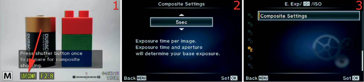
Figure 6.66C: Selecting an exposure time while in Live Composite mode
Use these steps to set the Composite Settings after you activate the Live Composite system:
1. Set the camera to Manual (M) mode on the Mode Dial.
2. Using the Rear Dial, select LIVECOMP from the shutter speed settings. The LIVECOMP choice is the slowest available shutter speed; it is the last setting past BULB and LIVE TIME (figure 6.66C, image 1, red arrow).
3. Press the Menu button to directly enter the Composite Settings screen (figure 6.66C, image 2). Choose an Exposure time per image to be applied equally to each frame in the composite image. Your choices in the up/down menu range from 1/2 second (1/2sec) to 60 seconds (60sec).
4. Press the OK button to select the exposure time, and the camera will switch to the screen in figure 6.66C, image 3. Nothing needs to be done on this screen, so press the Shutter button slightly to return to the first screen in the series (figure 6.66C, image 1). The time value is selected and ready to use. The next few steps will take the pictures to be composited.
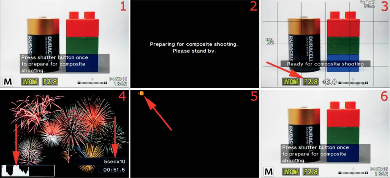
Figure 6.66D: Taking pictures with the Live Composite system
5. The Live Composite screen (figure 6.66D, image 1) will display this message: Press shutter button once to prepare for composite shooting.
6. Press the Shutter button all the way down once, and the camera will prepare to take the composite series. A dark screen will open for a few seconds that says, Preparing for composite shooting. Please stand by (figure 6.66D, image 2).
7. The next screen says, Ready for composite shooting. It will use the settings and exposure value you selected. Before proceeding, use the Front Dial to set the aperture (figure 6.66D, image 3, red arrow). Then focus the camera on the subject or on the area where the subject will appear. It may be a good idea to use manual focus for subjects that will appear later in the series, such as a fireworks show. After you have focused the camera, press the Shutter button completely down one time to start the exposures.
8. The camera will start taking a series of timed pictures until one of the following occurs: you stop Live Composite by pressing the Shutter button fully; three hours have passed; or the battery dies. Three hours is the maximum run time for the Live Composite system before it automatically shuts down. At the left red arrow in figure 6.66D, image 4, you can see that the camera is building a live histogram as it takes the exposures. You can watch this histogram to prevent overexposure as additional images are taken over time. At the right red arrow in image 4, you can see the camera counting down the exposures and time. The image shows 5secx10, which means each exposure is 5 seconds long (5sec), and 10 exposures have been made so far (x10). Just beneath the exposure count is a timer that displays the actual time of the Live Composite session. The time is counted in 1/2 second increments up to three hours. During the series of exposures you can move the camera to position a bright subject somewhere else in the frame, such as in figure 6.66A.
9. Stop the Live Composite session by completely pressing the Shutter button once. The camera monitor will go black except for the orange memory card access symbol in the upper-left corner, which will blink as the camera finishes combining the images (figure 6.66D, image 5). Finally, the camera will display the finished composite picture, according to the value you chose in Setup Menu > Rec View (default 1/2 second), then the camera will switch back to the main Live Composite screen so you can prepare for another session (figure 6.66D, image 6).
10. If you would like to shoot another Live Composite series, simply repeat steps 3 through 9. If you are done shooting in Live Composite, select a different shutter speed to exit the Live Composite system.
Note: The camera will automatically adjust the brightness of the monitor during a Live Composite session. It may be best to use an HLD-7 battery pack so you will have two batteries available for long exposures if you shoot in Live Composite for hours at a time. Finally, if you want to see the number of composited shots in the final image, you can find it later in your computer with the included Olympus Viewer 3 software.
Custom Menu F. [Flash] Custom
The F. [Flash] Custom menu is primarily composed of functions that directly affect how the flash system works. First we will take a look at the opening menu screen for the F. [Flash] Custom functions (figure 6.67).
To enter the menu, select F. [Flash] Custom from the Custom Menu and scroll to the right. There are three functions in the F. [Flash] Custom menu. Let’s consider each of them in detail.
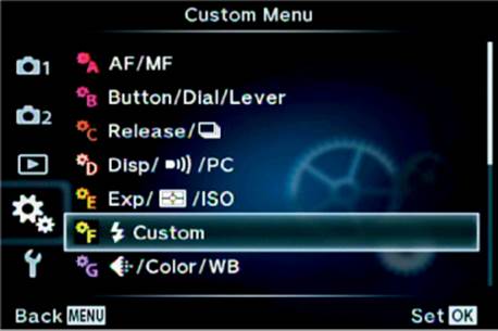
Figure 6.67: The opening menu selection for the F. [Flash] Custom functions
[Flash] X-Sync
The [Flash] X-Sync function (X-Sync) sets a maximum shutter speed for shooting with an electronic flash unit that is mounted in the Hot shoe and turned on.
The X-Sync speed is necessary because the shutter blades in front of the sensor have to be out of the way before the flash can fire. If a shutter blade partially blocks the sensor, a dark shadow or band will appear in the image.
The X-Sync name comes from the old days when lenses had an actual X on them. You had to select the setting with a lever when you used flash. The old mechanical clockwork shutters had an electrical contact that closed the circuit and fired the flash when the shutter blades were completely out of the way. On the EM-1, X-Sync is controlled by an electronic timing circuit instead of a mechanical contact.
The E-M1 allows a faster X-Sync shutter speed than many cameras. You can select an X-Sync speed from 1/60 second to 1/320 second. The 1/320 X-Sync value may be obtained only with the small FL-LM2 flash attachment that came with your E-M1. Other flash units, such as the Olympus FL-600R, cause the camera to drop back to 1/250 second as an X-Sync maximum. The user’s manual (page 110) says the X-Sync maximum is “1/320 sec when using the supplied external flash FL-LM2, and 1/125 sec when using a commercially available specialty flash.” Depending on which flash unit you are using, the maximum X-Sync value will vary between 1/125 second and 1/320 second.
The [Flash] X-Sync function controls the upper limit or maximum shutter speed you can use with flash (without banding). The next subsection will consider the [Flash] Slow Limit, which controls the slowest or minimum shutter speed you can use with flash in certain exposure modes. You can use the two functions—[Flash] X-Sync and [Flash] Slow Limit—to control the upper and lower limits of the shutter speed when you use flash to get a mixture of flash light and ambient light. We will discuss how to blend the two types of light in the next subsection, [Flash] Slow Limit.
The camera will use the maximum X-Sync value only when you are shooting in a very bright environment in direct flash (Fill In) mode to prevent the ambient light from overly influencing the exposure. Most of the time, in low ambient light, the camera will automatically select a somewhat slower shutter speed, such as 1/60 second, unless you have [Flash] Slow Limit (next subsection) set so it cannot use a speed that low.
Let’s examine how to select an X-Sync value that matches your needs.
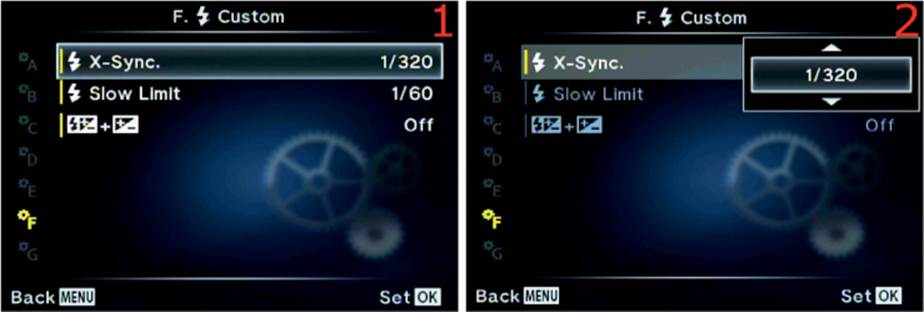
Figure 6.68: Selecting an X-Sync value
Use the following steps to choose a maximum shutter speed to use with flash:
1. Select [Flash] X-Sync from the F. [Flash] Custom menu and scroll to the right (figure 6.68, image 1).
2. Use the up or down key of the Arrow pad to choose one of the eight brightness levels, which range from 1/60 to 1/320 (figure 6.68, image 2). The factory default setting is 1/320 second.
3. Press the OK button to Set the value.
Settings Recommendation: I normally use 1/320 second for the X-Sync value when I am depending on the flash unit for lighting a subject. However, when I am trying to synchronize flash with evening light outdoors, I may use a combination of the [Flash] X-Sync speed and [Flash] Slow Limit to allow ambient light to influence the exposure for a more balanced look. The camera has a nice range of shutter speeds for slow flash use.
[Flash] Slow Limit
The [Flash] Slow Limit function allows you to control the lower shutter speed limit when you use flash photography (slow flash). You may need this function when you want ambient light combined with light from a flash unit to illuminate the exposure. You may want ambient light to be the primary source of exposure and have the flash provide a little fill light. Or you may want the flash to provide the main illumination, with ambient light opening up the shadows in the background. You may even be using more than one flash in a wireless group of units that work with ambient light.
[Flash] Slow Limit works in partnership with the [Flash] X-Sync function (previous subsection) by allowing you to set the lower limit of the shutter speed when you shoot with flash; the shutter speed can be as slow as 30 seconds. The [Flash] X-Sync function controls the upper shutter speed limit, which cannot exceed 1/320 second and can be set as slow as 1/60 second.
When you have the camera set to Program (P) or Aperture-priority (A) mode on the Mode Dial, the camera controls the shutter speed and you control the aperture. Therefore, the lower shutter speed limit provided by the [Flash] Slow Limit function is important when you are using flash in P and A modes.
If you are using Shutter-priority (S) or Manual (M) mode on the Mode Dial, the [Flash] Slow Limit function has no effect because you can set the lower shutter speed to be as long (slow) as you would like.
Therefore, if you want to balance the illumination from the flash and the ambient light, you can either do it manually in S or M mode, or you can use P or A mode and depend on the [Flash] Slow Limit function to provide the minimum flash shutter speed.
To effectively balance the ambient light with the flash requires experimentation and experience and is beyond the scope of this book. You know that the camera cannot exceed 1/320 second for a maximum shutter speed ([Flash] X-Sync), and now you also know that the camera will allow you to set a minimum shutter speed ([Flash] Slow Limit). Therefore, you can use mostly ambient light by lengthening the shutter speed with a slower setting under [Flash] Slow Limit to let in more ambient light while the flash provides a burst of light for filling in some shadows.
Or you can use a shutter speed in [Flash] Slow Limit that is somewhat closer to the shutter speed in [Flash] X-Sync so the flash will provide the main light source while ambient light provides some background fill.
You will need to experiment with these two settings to find the appropriate balance for what you are trying to accomplish. Be sure to use a tripod if you use shutter speeds in [Flash] Slow Limit that are slow enough to allow camera shake or subject movement, which will appear in the image. Otherwise ghosting will be apparent in the image where the flash-lit portion of the subject is sharp and the ambient-lit portion of the subject is blurred.
Let’s examine how to set the [Flash] Slow Limit function for various shutter speeds.
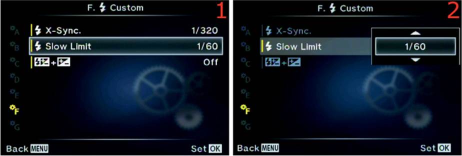
Figure 6.69: Setting a minimum shutter speed for flash photography
Use the following steps to choose a minimum shutter speed to use with flash:
1. Select [Flash] Slow Limit from the F. [Flash] Custom menu and scroll to the right (figure 6.69, image 1).
2. Use the up or down key of the Arrow pad to choose a minimum flash shutter speed, ranging from 30 seconds to 1/320 second (figure 6.69, image 2). The factory default setting is 1/60 second.
3. Press the OK button to Set the value.
Note: On page 110 of the user’s manual, under Flash timing-synchronous, the text seems to say that the camera obeys a photography rule called reciprocal of focal length. This rule states that you should not make an exposure with, let’s say, a 200mm lens at a shutter speed of less than 1/200 second because anything slower may cause camera shake. I have tested the EM-1 extensively to see how it obeys this rule when I have [Flash] Slow Limit set to a much slower minimum shutter speed for flash. I found that the camera attempts to obey this rule by trying to keep the shutter speed higher than the reciprocal of the focal length (100mm = 1/100 second shutter speed); however, if there is not enough light to obey this rule, the camera will abandon the rule and drop the shutter speed well below the reciprocal of the focal length. Therefore, be careful when you shoot with the [Flash] Slow Limit function set to a slow shutter speed, regardless of the focal length of the lens. You must use a tripod if the shutter speed is too slow.
Settings Recommendation: I raise the minimum flash shutter speed to 1/100 or 1/125 second when I am shooting with flash indoors. I find that often 1/60 second (the default) is too slow and may allow some ghosting to occur, especially at weddings where I am shooting people walking down the aisle when fairly bright ambient light influences the exposure. If the shutter is open for 1/60 second, the flash will make a nice sharp picture for a short segment of the exposure duration, and ambient light continues to illuminate the subject for the remainder of the exposure duration, resulting in a ghosted blur.
On the other hand, when I am shooting in bright ambient light outside, I may allow the shutter speed to remain slower and take advantage of some ambient light with flash fill. I use a smaller aperture to keep from overexposing the subject.
This type of thing is always an experiment and has to be balanced. You can take advantage of your camera’s powerful tools to get the results you want.
[Flash Compensation] + [Exposure Compensation]
This function allows you to combine exposure compensation and flash compensation, and you can control both at the same time with the Front Dial.
Normally, with this function set to Off, when you want to do exposure compensation for your image you simply turn the Front Dial (in P, A, and S modes) and dial in exposure compensation from –5.0 EV to +5.0 EV.
However, when you have a flash unit mounted on your camera, its output is not increased or decreased based on the exposure compensation. Instead, the camera simply opens or closes the aperture, or raises or lowers the shutter speed, to provide more or less exposure. The flash provides a constant output.
Sometimes increasing or decreasing the entire exposure is not sufficient. Maybe you would like to increase or decrease the power of the flash output to perform what Olympus calls “flash intensity control.” By setting this function to On, whenever you turn the Front Dial to increase or decrease the camera exposure compensation, the compensation request also affects the flash unit. For example, if you raise the exposure compensation by 1.0 EV, the flash will also raise its power output by 1.0 EV. If you use negative exposure compensation to underexpose the image by 0.3 EV, the flash will also lower its power output by 0.3 EV.
This gives you the ability to control the intensity of the flash output very quickly, without having to use the flash unit’s compensation controls. It allows you to raise or lower the brightness of the subject visually in case the flash is too strong or too weak.
Basically, Olympus gives you flash intensity control without having to use the camera menus or external flash unit menus. It is a quick way to control the intensity of the flash with the Front Dial when you need more or less light from the flash unit, and you’ll still have time to make other adjustments.
Let’s examine how to enable or disable [Flash Compensation] + [Exposure Compensation].
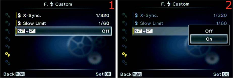
Figure 6.70: Combining flash compensation with exposure compensation
Use the following steps to connect or disconnect flash compensation with exposure compensation by using the Front Dial:
1. Select the dual symbols representing [Flash Compensation] + [Exposure Compensation] from the F. [Flash] Custom menu and scroll to the right (figure 6.70, image 1).
2. Choose On to combine flash and exposure compensation, or choose Off to disconnect the two (figure 6.70, image 2). The factory default setting is Off. This function takes effect only when a flash unit is mounted in the Hot shoe.
3. Press the OK button to Set the value.
Settings Recommendation: I leave this function set to On because I love the way it lets me control the intensity of the flash when I turn the Front Dial on my camera in P, A, and S modes on the Mode Dial. Since it has no effect when a flash unit is not mounted, it is safe to leave it on all the time.
If you are an accomplished strobist who wants to completely separate the two forms of compensation to vary the exposures for the background and the subject, you may want to leave flash and exposure compensation separated and use the camera’s and flash unit’s manual exposure compensation controls.
For most people the power of this function is very useful.
Custom Menu G. [Record Mode]/Color/WB
The G. [Record Mode]/Color/WB menu is primarily composed of functions that control JPEG image quality, image size, and color balance.
These functions do not affect a RAW file, other than providing initial settings when you view them on your computer, because each setting can be changed after the fact.
Think of these options as in-camera RAW to JPEG conversion functions (in-camera post-processing) that you would otherwise have to do on your computer after you shoot a RAW file and convert it to JPEG manually.
We will start examining the functions by taking a look at the opening menu screen for the G. [Record Mode]/Color/WB functions in figure 6.71.
To enter the menu, select G. [Record Mode]/Color/WB from the Custom Menu and scroll to the right. There are eight functions inside the G. [Record Mode]/Color/WB menu. Let’s consider each of them in detail.

Figure 6.71: The opening menu selection for the G. [Record Mode]/Color/WB functions
[Record Mode] Set
Your E-M1 can create three JPEG image sizes: Large (L), Middle (M), and Small (S). All three sizes can use four levels of compression (quality) to reduce the file sizes: Super Fine (SF), Fine (F), Normal (N), and Basic (B). Each of these quality types have different lossy compression ratios, with Super Fine having the least amount of compression and Basic having the most (table 6.10).
You can combine JPEG types in the [Record Mode] Set function and they will appear on the [Record Mode] menus of the camera, where you select an image format (i.e., JPEG, RAW, JPEG+RAW).
Table 6.10 shows the available JPEG sizes and qualities, compression ratios, and Pixel Counts. The Pixel Count for the Middle and Fine JPEG sizes is controlled by the Pixel Count function (next subsection):
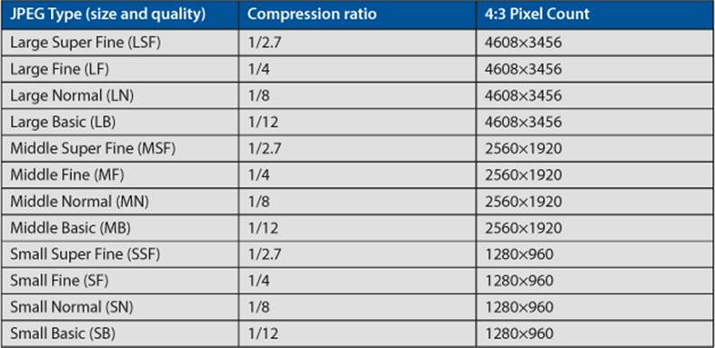
Table 6.10: JPEG size and quality, compression ratio, and 4:3 Pixel Count
The lower the compression ratio, the higher the image quality and the larger its physical storage size on your computer hard drive. You can add any of these JPEG size and quality settings to the 1, 2, 3, and 4 positions of the screen shown in figure 6.72, image 2. Let’s see how.
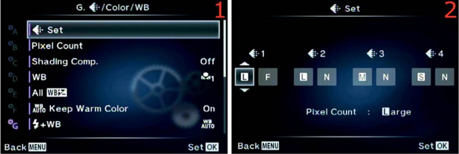
Figure 6.72: Using [Record Mode] Set to choose JPEG type choices for camera menus
Use the following steps to set various JPEG types in four available selection positions:
1. Select [Record Mode] Set from the G. [Record Mode]/Color/WB menu and scroll to the right (figure 6.72, image 1).
2. In figure 6.72, image 2, you will see four available JPEG type selection boxes, numbered 1, 2, 3, and 4. The factory default is LF, LN, MN, and SN. Using table 6.10 as a reference, choose any of the characters from the values in parentheses under the JPEG Type column and set them in these four positions. Whatever you put in the four positions will appear on any camera menus that allow you to select an image format type (JPEG, RAW, and JPEG+RAW).
3. Press the OK button to Set the value.
Settings Recommendation: I have no need for the smaller sizes, so I use LSF, LF, MF, and SF in my [Record Mode] Set function. I prefer to shoot in either RAW or JPEG Large Super Fine (LSF) most of the time.
However, if you need to put a lot of images on a small memory card, or if you are shooting images for use on a website, you could use any of the other size and quality settings. Anything you choose in [Record Mode] Set will appear on the Record Mode menus (image format selection screens).
Pixel Count
The normal Pixel Count for a Micro Four Thirds (4:3) image on the E-M1 is 4608×3456. This is considered the Large Pixel Count size. The Pixel Count directly affects the megapixel size of the image. Simply multiply the Pixel Count to find the total megapixels. For instance, the large 4:3 Pixel Count results in an approximate size of 16 MP (4,608×3,456 = 15,925,248, or 15.9 million pixels).
The image does not use the full Pixel Count of the camera sensor because some pixels around the edges are used for color control. However, camera companies usually advertise the camera’s megapixel rating based on the actual size of the sensor. That is the difference between the actualand effective Pixel Count; the effective count is what you actually get for a usable picture, and the actual count is the full sensor Pixel Count. Usually there is a megapixel or two difference between the actual pixel count (which is usually not provided by camera manufacturers) and the effective pixel count (the 4608×3456 image size).
Note: There are other Image Aspects (aspect ratios) and Large Pixel Counts available, such as 3:2, 1:1, and 16:9. When you select one of the alternate Image Aspect ratios, the Pixel Count for their Middle and Small sizes will vary a bit from those listed under figures 6.73A and 6.73B, which is for the 4:3 Image Aspect. The additional image sizes are controlled by the Image Aspect function in Shooting Menu 1 (Shooting Menu 1 > Image Aspect). Selecting one of the other aspect ratios will change the Pixel Count for Large, Middle, and Small JPEG images. None of the Large size Pixel Counts are variable, but the Middle and Small Pixel Counts are. The Medium and Small Pixel Count can change depending on your selections in this function.
Let’s examine how to choose a different Pixel Count for when you need to shoot a Middle or Small image, such as for a website. First we will examine how to select one of the four available Middle Pixel Counts.
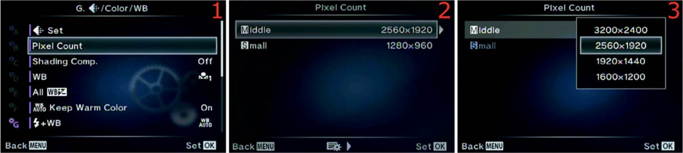
Figure 6.73A: Choosing a Middle Pixel Count size
Use the following steps to choose a Middle Pixel Count size:
1. Select Pixel Count from the G. [Record Mode]/Color/WB menu and scroll to the right (figure 6.73A, image 1).
2. Choose Middle from the Pixel Count menu and scroll to the right (figure 6.73A, image 2).
3. The factory default Middle Pixel Count is 2560×1920 (figure 6.73A, image 3). However, you can choose from three additional Pixel Counts: 3200×2400, 1920×1440, and 1600×1200.
4. Press the OK button to Set the new Middle Pixel Count value.
Next let’s examine how to select one of the three available Small Pixel Counts.
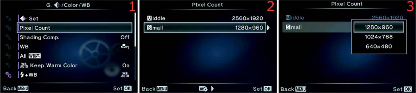
Figure 6.73B: Selecting the Small Pixel Count size
Use the following steps to choose a Small Pixel Count size:
1. Select Pixel Count from the G. [Record Mode]/Color/WB menu and scroll to the right (figure 6.73B, image 1).
2. Choose Small from the Pixel Count menu and scroll to the right (figure 6.73B, image 2).
3. The factory default Small Pixel Count is 1280×960 (figure 6.73B, image 3). However, you can choose from two additional Pixel Counts: 1024×768 and 640×480.
4. Press the OK button to Set the new Small Pixel Count value.
Settings Recommendation: Since I rarely stray from Large Pixel Count because I want to use every available pixel for maximum image size, I don’t often select Middle or Small Pixel Count sizes.
However, some sizes exactly fit, or are very close to, HDTV, computer monitor, tablet, and smartphone sizes. If you shoot specifically for these devices, other Pixel Count sizes may come in handy.
Shading Comp.
With many lenses there can be some light falloff at the edges of the frame. Certain wide-angle lenses have this issue. In fact, most lenses have a little light falloff in the peripheral areas—that’s just the laws of physics at work. Normally you can correct this problem during post-processing on a computer, especially for RAW files.
However, you may not have the time or inclination to post-process images, so the camera offers a solution. If you have lenses that are especially prone to light falloff, you can enable Shading Comp. and let the camera correct the peripheral dimness for you.
Let’s examine how to enable Shading Comp.
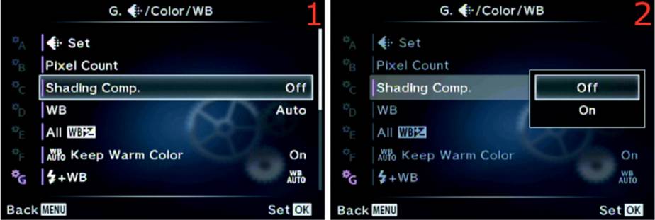
Figure 6.74: Changing the Shading Comp. setting
Use the following steps to enable or disable the Shading Comp. function:
1. Select Shading Comp. from the G. [Record Mode]/Color/WB menu and scroll to the right (figure 6.74, image 1).
2. Choose Off or On from the Shading Comp. menu and scroll to the right (figure 6.74, image 2). If you choose On, the camera will correct for light falloff automatically, according to the type of lens you are using.
3. Press the OK button to Set the value.
Note: Brightening the edges of the image can lead to a little additional noise in those areas. Shading Comp. does not work for teleconverters and extension tubes.
Settings Recommendation: I have found that many Micro Four Thirds lenses are already corrected for light falloff problems, and I usually make any needed corrections when I post-process my RAW images in Photoshop. Therefore, I don’t often use this function.
However, this is a useful function, especially for JPEG shooters. Try it for any lenses that may have light falloff issues and see if it helps.
WB
Normally white balance (WB) is used to adjust the camera so that whites are truly white and other colors are accurate under any given light source. You can also use the WB controls to deliberately introduce color casts into your image for interesting special effects.
Camera WB color temperatures are backwards from the Kelvin scale we learned in school for star temperatures. Remember that a red giant star is cool, and a blue-white star is hot. The WB color temperatures are backwards because the WB system adds color to make up for a deficit of color.
For instance, fluorescent light lacks blue, which makes the subject appear greenish yellow. When blue is added, the image is balanced to a more normal appearance.
Another example is when you shoot on a cloudy, overcast day. The cool ambient light could cause the image to look bluish. The Auto WB control in your camera sees the cool color temperature and adds some red to warm up the colors a bit. The normal WB on a cloudy, overcast day might be about 6000K.
Remember that we use the Kelvin temperature range in reverse and that red colors are warm and blue colors are cool. Even though this is backwards from what we were taught in school, it fits our situation better. To photographers, blue seems cool and red seems warm! Just don’t let your astronomer friends convince you otherwise.
White Balance Fundamentals
Understanding WB in a fundamental way is simply realizing that light has a range of colors that go from cool to warm. We can adjust our cameras to use the available light in an accurate and neutral, balanced way that compensates for the actual light source. Or we can allow a color cast to enter the image by unbalancing the settings. In this chapter we will discuss this from the standpoint of the E-M1 controls and how they deal with WB.
Using the WB Function
The E-M1 WB range varies from a very cool 2000K to a very warm 14,000K. What does that mean?
Figure 6.75A shows the same picture adjusted in Photoshop, with the use of photo filters, to three WB Kelvin (K) settings. Notice how the image in the center is about right, the image on the left is cooler (bluish cast), and the image on the right is warmer (reddish cast).

Figure 6.75A: One image with three WB Color Temperature settings
The same adjustments we made in the good old days with film and filters can now be achieved with the WB settings built in to the E-M1. To achieve the same effect as daylight film and a warming filter, simply select the Cloudy WB setting while shooting in normal daylight. This sets the E-M1 to balance at about 6000K, which makes nice warm-looking images. If you want to really warm up the image, choose the WB called Shade, which sets the camera to 7500K.
On the other hand, if you want to make the image appear cool or bluish, try using the Fluorescent (4000K) or Incandescent (3000K) settings in normal daylight.
Remember, the color temperature shifts from cool values to warm values. The E-M1 can record your images with any color temperature from 2000K (very cool or bluish) to 14,000K (very warm or reddish) and any major value in between. There is no need to carry different film emulsions or filters to deal with the range of color in light. The E-M1 has easy-to-use color temperature controls.
Normally you will set the WB from the Live Control screen by pressing the OK button while in Live View. However, you can also use this WB function to set the WB and even fine-tune it (add a color bias).
Here is a list of the 13 WB types you will find on the WB selection screen. Note that six of the WB symbols are followed by a number, such as 5300K. This is the color temperature value for that particular WB setting. We will also discuss how to do an ambient WB reading.
• Auto: Camera automatically chooses the best WB setting
• ![]() [Sunlight] 5300K: Direct sunlight pictures
[Sunlight] 5300K: Direct sunlight pictures
• ![]() [Shade] 7500K: Shooting in the shade
[Shade] 7500K: Shooting in the shade
• ![]() [Cloudy] 6000K: Taking pictures on an overcast day
[Cloudy] 6000K: Taking pictures on an overcast day
• ![]() [Incandescent] 3000K: Shooting under an old-fashioned light bulb
[Incandescent] 3000K: Shooting under an old-fashioned light bulb
• ![]() [Fluorescent] 4000K: Making pictures under fluorescent light
[Fluorescent] 4000K: Making pictures under fluorescent light
• [Underwater]: Taking pictures with your E-M1 while underwater (in a waterproof underwater housing)
• ![]() [Flash] 5500K: Making images with an electronic flash unit providing the main light source
[Flash] 5500K: Making images with an electronic flash unit providing the main light source
• [One-Touch Capture WB] 1: Set and store WB with ambient light reading of a white or gray card (must use the Live Control screen to do the reading)
• [One-Touch Capture WB] 2: Set and store WB with ambient light reading of a white or gray card (must use the Live Control screen to do the reading)
• [One-Touch Capture WB] 3: Set and store WB with ambient light reading of a white or gray card (must use the Live Control screen to do the reading)
• [One-Touch Capture WB] 4: Set and store WB with ambient light reading of a white or gray card (must use the Live Control screen to do the reading)
• CWB (Custom White Balance): Choose a WB color temperature manually, from a range of 2000K to 14,000K
First, let’s consider how to do a One-touch Capture WB reading.
One-Touch Capture WB Reading
For the most accurate WB, it is best to do an ambient light reading from a white or gray card under the same light source as your subject. This will adjust the camera to use the correct WB while you are under that light source. Be sure to set the WB back to Auto or do a new ambient light reading if the light source changes.
In the E-M1 user’s manual, Olympus calls an ambient light WB reading both One-touch WB and Capture WB. Therefore, I am combining the two and calling it a One-Touch Capture WB reading or simply a Capture WB reading. Your camera has four memory locations to store WB readings. If you shoot a lot under a certain light source, you can store a Capture WB reading in one location and use it again later.
Let’s examine how to do a Capture WB reading. Use a white or gray card if you have one; otherwise you can use a blank sheet of white printer paper.
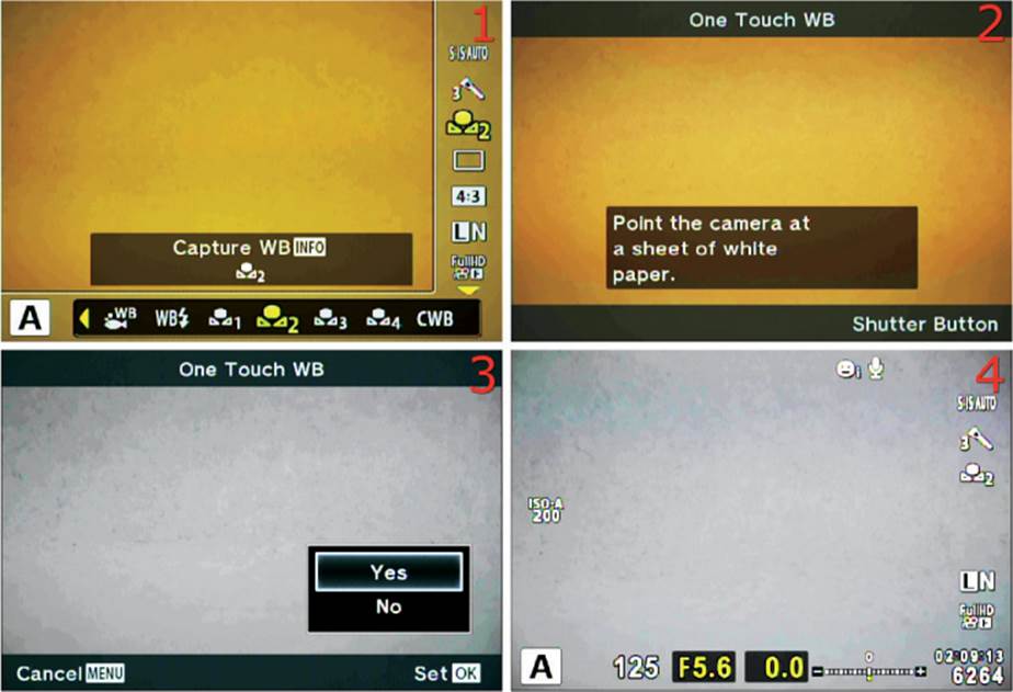
Figure 6.75B: Making a One-Touch Capture WB reading from a white card
Use the following steps to do a One-Touch Capture WB reading from a white or gray card:
1. Press the OK button while in Live View to open the Live Control screen. Find the WB function on the right side by scrolling up or down with the Arrow pad. After you have selected the WB function (figure 6.75B, image 1), scroll to the left or right with the Arrow pad until you highlight one of the Capture WB memory locations. In figure 6.75B, image 1, I selected memory location 2 (looks like a flower with number 2 to the right of it). You have chosen where you are going to store the WB reading and are now ready to take the ambient light reading from the card.
2. Press the Info button to open the One Touch WB screen. You can tell that I am about to take a reading from an incandescent light source because of the warm orange look in figure 6.75B, images 1 and 2. As instructed on the screen in image 2, place the card under the light source you want to measure, then press the Shutter button all the way down as if you are taking a picture of it. The camera will fire the shutter and measure the color temperature of the light source that reflects from the card.
3. A WB reading is ready to be stored in the current Capture WB memory location; however, you must approve it first by scrolling up and selecting Yes from the menu then pressing the OK button (figure 6.75B, image 3). If you do not like the reading, select No to cancel and repeat steps 1 and 2. If you approve of the WB reading it will be stored in the memory location for immediate use and later recall. You can select it on the Live Control screen or within the WB function (this function).
4. After you have approved the WB reading and pressed the OK button, the camera switches to the normal Live Control screen, with the new WB in place. You can tell by looking at the Live View screen in figure 6.75B, image 4, that the camera successfully adjusted the WB under the ambient, incandescent light source so that whites look white and other colors look the same as in real life.
Note: In addition to doing a One-Touch Capture WB reading, you can select any of the 13 available White Balance choices from the Live Control screen (figure 6.75B, image 1). Using the Live Control screen is much faster than scrolling down to the Custom Menu and selecting the WB function to choose a WB setting.
You must use the Live Control screen to do a One-Touch Capture WB reading, but you cannot adjust the amber–blue (A–B) and green–magenta (G–M) color balance of an individual WB setting. You must use the WB function to fine-tune the A–B and G–M color balance for an individual WB setting, but you cannot do a One-Touch Capture WB reading from the WB function.
Even though the 13 Live Control White Balance settings and the 13 Custom Menu White Balance settings are the same WB settings, you must use the Live Control WB to do a One-Touch Capture WB reading and the Custom Menu WB function for WB color adjustment. This is an unusual design, indeed. The only thing they have in common is the ability to select an individual WB setting for camera use and to choose a Custom WB (CWB).
Now let’s see how to choose and fine-tune an existing WB setting from the Custom Menu WB function.
Choosing and Fine-Tuning a WB Setting from the Custom Menu
In addition to the Live Control screen we previously considered, you can select any of the 13 White Balance settings from the WB function. You can also adjust the amber–blue (A–B) and green–magenta (G–M) ratios for individual WB settings. Let’s see how!
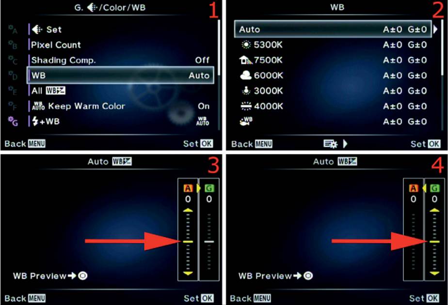
Figure 6.75C: Choose and adjust an individual WB setting
Use the following steps to choose a WB value and modify the color of individual WB settings:
1. Select the WB function from the G. [Record Mode]/Color/WB menu and scroll to the right (figure 6.75C, image 1).
2. Choose one of the individual WB settings, such as Auto, Sunshine (5300K), or Shade (7500K), as seen in figure 6.75C, image 2. I chose the Auto WB setting. Refer to the previous list of 13 WB settings to determine what each WB setting does. If you don’t need to adjust the color balance (A–B and G–M) of an individual WB Setting, simply press the OK button to select a WB setting, and skip the next three steps.
3. If you want to fine-tune a certain WB setting you can do so by highlighting it and scrolling to the right. I scrolled to the right on the Auto WB setting, which led me to the screen in figure 6.75C, image 3. I can now fine-tune the color balance of the Auto setting. You can see at the point of the arrow in image 3 that there is an adjustment available. You can slide the yellow bar up toward A (amber) to increase amber for this WB setting, or you can slide it down to reduce amber (add blue). You can see a WB Preview at any time by pressing the Movie button, which causes the camera to take a temporary picture of the subject, with the fine-tuned WB value applied, and display it on the monitor. If you need to fine-tune it some more, simply move the slider again and press the Movie button again to see the results. Do this as many times as you want to fine-tune the WB setting. When you are done, either press the OK button to Set the fine-tuned amber (A–B) ratio and skip the rest of these steps, or scroll to the right to move to the green (G–M) ratio adjustment.
4. After you have fine-tuned the amber (A–B) color balance, you can fine-tune the green (G–M) color balance by scrolling right and selecting the sliding adjustment shown in figure 6.75C, image 4. You can add green to the WB setting by sliding the yellow bar up toward G (green), or you can scroll down to decrease green (add magenta). Press the Movie button to take a temporary picture (WB Preview), examine the color balance, and make further adjustments if necessary. When you are satisfied with the G adjustment, press the OK button to set the value.
5. Whenever you Set one of the color values in previous steps by pressing the OK button, the camera will return to the WB function on the Custom Menu. You have modified this WB setting for all future pictures until you reset or modify it.
6. Repeat these steps for any other individual WB settings you want to fine-tune.
Choosing a Custom White Balance (CWB)
If you would like to experiment with entering direct Kelvin values into the camera, or if you have specific color temperature needs, you can use the CWB setting under the WB function to choose a custom WB from 2000K to 14,000K. Let’s examine how!
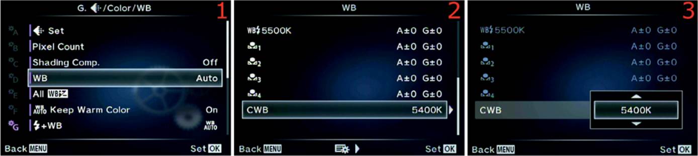
Figure 6.75D: Manually choose a Kelvin WB value from 2000K to 14,000K
Use the following steps to choose a specific custom WB value:
1. Select the WB function from the G. [Record Mode]/Color/WB menu and scroll to the right (figure 6.75D, image 1).
2. Choose the CWB setting (at the end of the list of 13 WB values) and scroll to the right (figure 6.75D, image 2).
3. The CWB setting allows you to experiment with specific values from cool (2000K) to warm (14000K), as shown in figure 6.75D, image 3. If you shoot in a studio and the light does not vary, you can manually find the best WB setting for your product images and portraits. The factory default is 5400K under CWB. Choose the best setting for your style of photography from the up/down menu.
4. Press the OK button to Set the custom WB value. In the future you can choose and use this CWB setting from the WB settings in the Live Control screen or here on the WB function menu.
Settings Recommendation: White balance is an art in itself, especially for JPEG shooters. For RAW shooters this setting does not matter because the WB of a RAW file can be changed after the fact.
You can let the camera choose the best WB by using Auto mode, which is what I often do because I shoot in RAW mode and can change the WB after the fact. As mentioned previously, for a RAW shooter the WB setting is not as critical as it is for a JPEG shooter. RAW files can be changed to a different WB setting after the picture is taken, but for a JPEG the WB value is a permanent part of the image.
You must use an accurate WB if you shoot JPEGs. Although you can vary the color balance somewhat in a JPEG image, it never is quite right after it has been changed.
You can choose a preset WB value (e.g., Cloudy, Incandescent, Fluorescent), do a One-Touch Capture WB reading from a white or gray card, or enter a custom WB value under CWB. The E-M1 has a full range of WB controls that allow you to use whatever is most convenient.
All WB +/–
In the previous section (WB) we discussed fine-tuning the colors of individual White Balance (WB) settings. You could change the amber–blue (A) ratio or the green–magenta (G) ratio for each WB setting individually; CWB cannot be modified.
The All WB +/– function is for people who dislike the color balance of all WB functions. All WB +/– allows you to adjust the amber and green ratios for all WB settings at the same time (12 of the 13 WB settings, not including CWB). When you use this function to set the amber–blue (A) ratio, and the green–magenta (G) ratio, it changes the color balance of every WB setting except CWB.
Let’s examine how to make a global WB compensation (fine-tuning) adjustment.

Figure 6.76A: Adjust the A and G color ratios for all WB settings at once (except CWB)
Use the following steps to modify the amber–blue ratio (A), and green–magenta ratio (G), for all WB settings at the same time (except CWB):
1. Select the All WB +/– function from the G. [Record Mode]/Color/WB menu and scroll to the right (figure 6.76A, image 1).
2. Choose All Set from the All WB +/– menu and scroll to the right (figure 6.76A, image 2).
3. You can see at the point of the arrow in figure 6.76A, image 3, that there is an adjustment available. You can slide the yellow bar up toward A (amber) to increase the amber color for all WB settings, or slide it down to reduce amber (add blue). You can see a WB Preview of the current WB setting that the camera is using by pressing the Movie button, which causes the camera to take a temporary picture of the subject, with the fine-tuned WB value applied, and display it on the monitor. If you need to fine-tune it some more, simply move the slider again and press theMovie button again to see the results. Do this as many times as you want to fine-tune the WB settings. When you are done, you can either press the OK button to Set the fine-tuned (A–B) ratio and skip the rest of these steps, or you can scroll to the right to move into the (G–M) ratio adjustment.
4. After you have fine-tuned the amber (A–B) color balance ratio, you can fine-tune the green (G–M) color balance ratio by scrolling right and selecting the sliding adjustment shown in figure 6.76A, image 4. You can add green to the WB setting by sliding the yellow bar up toward G(green), or you can slide it down to decrease green (add magenta). Press the Movie button to take a temporary picture (WB Preview), examine the color balance, and make further adjustments if necessary. When you are satisfied with the G adjustment, press the OK button to Set the value.
5. When you Set one of the color values in previous steps by pressing the OK button, the camera will return to the WB function on the Custom Menu. You have modified all WB settings, other than CWB, for all future pictures the camera will take using any WB setting, until you reset or modify them with this function.
If you make this comprehensive WB setting modification and later want to change all the WB settings back to their factory default values, you can use the upcoming steps to do so.
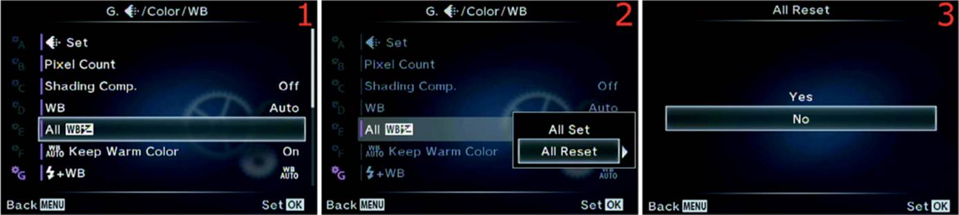
Figure 6.76B: Resetting all modified WB settings
Use the following steps to reset 12 of the 13 WB settings back to factory specs (except CWB):
1. Select the All WB +/– function from the G. [Record Mode]/Color/WB menu and scroll to the right (figure 6.76B, image 1).
2. Choose All Reset from the All WB +/– menu and scroll to the right (figure 6.76B, image 2).
3. Select Yes from the All Reset menu to reset all modified WB settings, or No to cancel (figure 6.76B, image 3).
4. Press the OK button to Set your choice.
Settings Recommendation: I may modify one or two of the WB settings, but never all of them at the same time. However, this function is good for people who modify multiple WB settings and need to return them all to factory specs at the same time. This may also be a good way to reset two or three WB settings you may have modified, instead of going into the menu settings for them one at a time.
WB Auto Keep Warm Color
When you take pictures under incandescent light sources or warm light sources (reddish lighting), the camera will either allow the image to be a little warmer than normal (keep warm color), or it will not.
Many people love the look of warm colors. The human eye seems to be attracted to reddish colors more than bluish colors. Therefore, many people leave this setting On, which keeps the warm colors when the light source is warm. Selecting Off will cause the camera to balance the light toward neutral. The effect is noticeable.
Let’s see how to choose one of the WB Auto Keep Warm Color settings.
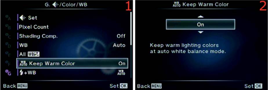
Figure 6.77: Choosing a color warmth setting
Use the following steps to choose color warmth over color neutrality when you shoot under warm light sources, such as incandescent:
• Select the WB Auto Keep Warm Color function from the G. [Record Mode]/Color/WB menu and scroll to the right (figure 6.77, image 1).
• Choose On from the WB Auto Keep Warm Color up/down menu to keep the warm colors, or choose Off to eliminate the warm colors (figure 6.77, image 2).
• Press the OK button to Set your choice.
Settings Recommendation: After testing this function under various light sources, I noticed that warm light sources have a marked effect when this function is set to On. I like warmer colors, but at times the effect seems a little strong to me, especially when I am shooting JPEGs and cannot adjust them later.
I suggest testing this function under various warm light sources to see if the image looks too warm. You may love the warmer images. More neutral images will be best for people who shoot JPEGs, where color accuracy is a must.
If you shoot in RAW mode, it makes no real difference because you can simply change the WB after the fact.
[Flash] + WB
This function allows you to choose various white balance (WB) types when you use electronic flash extensively. There are three settings for [Flash] + WB:
• Off: The camera will use the current WB setting (e.g., Sunshine, Cloudy, Incandescent) without regard for the color temperature of the flash unit.
• WB Auto: The camera will attempt to balance itself to whatever light source is illuminating the subject.
• WB [Flash]: The camera will use the Flash WB setting, which is about 5500K.
Let’s examine how to choose a [Flash] + WB value when you use flash to light the subject.
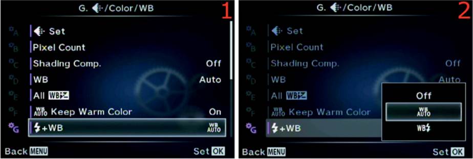
Figure 6.78: White balance choices for flash
Use the following steps to choose an appropriate WB setting for flash:
1. Select the [Flash] + WB function from the G. [Record Mode]/Color/WB menu and scroll to the right (figure 6.78, image 1).
2. Choose one of the settings from the [Flash] + WB menu (refer to the previous list of choices) (figure 6.78, image 2).
3. Press the OK button to Set your choice.
Settings Recommendation: If you are shooting in JPEG mode, the WB needs to be exactly right. Be careful to select the WB Flash setting from the Live Control screen (press OK in Live View) or the WB [Flash] setting on this function’s menu.
Alternatively, you can let the camera decide which WB is best by selecting WB Auto. It may not be the best idea to have a WB setting such as Cloudy or Fluorescent selected while shooting with flash because the color may be off.
For RAW shooters, this setting does not matter since the WB of a RAW file can be changed after the fact.
Color Space
Color space is an interesting and important part of digital photography. It helps your camera fit in to a much broader range of imaging devices. Software, printers, monitors, and other devices recognize which color space is attached to your image and use it, along with other color profiles, to help balance the image and produce the correct colors.
The two color spaces available on the E-M1 have different gamuts, or ranges of color. They are called sRGB and Adobe RGB. Let’s discuss color space briefly so you can make an educated choice.
Which Color Space Should I Choose?
Adobe RGB uses colors from a broad selection of the total color range that approximates human vision (called CIELAB in the graphics industry), so it has a wider gamut than sRGB (figure 6.79A). If you are taking images that might be printed commercially, Adobe RGB is often the best color space to use (see the sidebar called Which Color Space Is Best, Technically?).
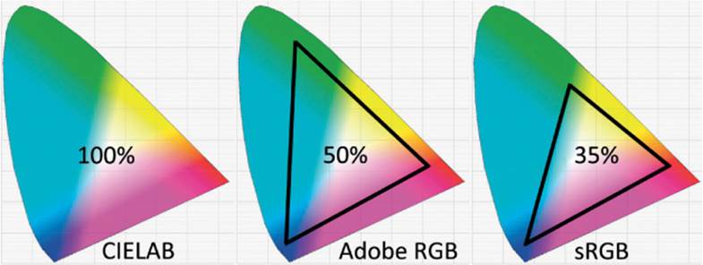
Figure 6.79A: CIELAB, Adobe RGB, and sRGB color spaces
After a JPEG file is created, either in a camera or on a computer, both the Adobe RGB and sRGB color gamuts are compressed into the same number of color levels. A JPEG has only 256 levels for each of its red, green, and blue (RGB) channels. However, since the Adobe RGB color space takes its colors from a wider spectrum, you will have a better representation of reality when there are lots of colors in your image.
If you shoot in RAW format a lot, you may want to consider using Adobe RGB to store the maximum number of colors in your image files for later use, even though, for reasons we’ll discuss in a moment, it really doesn’t matter in RAW mode. However, it is still a good idea to leave your camera set to Adobe RGB.
An E-M1 lossless compressed 12-bit RAW (ORF) image file can contain 4,096 levels of color per RGB channel, instead of the limited 256 levels in an 8-bit JPEG. Using Adobe RGB makes a lot of sense when you shoot in RAW mode because of its capacity to contain more colors as a base storage medium.
There are some drawbacks to using Adobe RGB, though. The sRGB color space is widely used in printing and display devices. Many local labs print with sRGB because so many point-and-shoot cameras use that format. If you try to print directly to some inkjet printers that are configured for sRGB using the Adobe RGB color space, the colors may not be as brilliant as with sRGB. If you aren’t going to modify your images in post-processing and plan to print them directly from your camera, you may want to use sRGB. If you shoot only JPEGs for computer display or Internet usage, it might be better to stay with sRGB for everyday shooting.
If you are a RAW shooter and regularly post-process your images, you should consider using Adobe RGB. You will have a wider gamut of colors to work with and can make your images the best they can be. Later you can convert your images to another color space (e.g., sRGB, CMYK, CIELAB) so you can get great prints from inkjet printers and other printing devices. Here is a rough way to look at it:
• Many people who regularly shoot in JPEG format use sRGB.
• Many people who regularly shoot in RAW format use Adobe RGB.
These are not hard-and-fast rules, but many people follow them. I shoot RAW a lot, so I often use Adobe RGB.
In reality, though, it makes no difference which color space you choose when you shoot in RAW because the color space can be changed after the fact in your computer. However, many people are not in the habit of changing the color space during a RAW to JPEG conversion. Therefore, if you need the extra color range, why not leave the camera set to Adobe RGB for later convenience? Why add an extra step to your digital darkroom workflow? If you are shooting for money—such as for stock image agencies—most companies expect you to use Adobe RGB. It has a larger color range, so it’s the quality standard for most commercial printing.
Now let’s examine how to choose the color space you want to use.
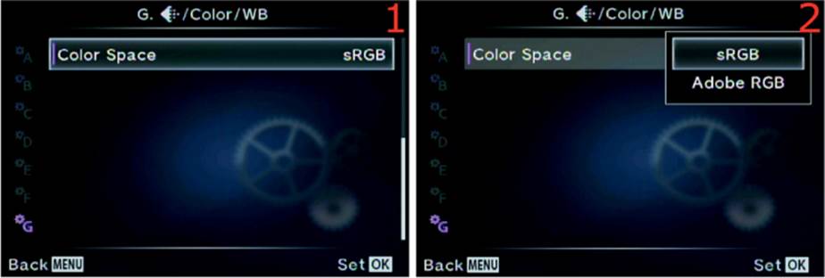
Figure 6.79B: Choosing a Color Space for your images
Use the following steps to choose an appropriate Color Space for your type of photography:
1. Select the Color Space function from the G. [Record Mode]/Color/WB menu and scroll to the right (figure 6.79B, image 1).
2. Choose one of the two Color Space settings (sRGB or Adobe RGB) from the Color Space menu after referring to the previous material in this chapter subsection (figure 6.79B, image 2).
3. Press the OK button to Set your choice.
Settings Recommendation: I use Adobe RGB most of the time because I shoot a lot of nature pictures with a wide range of color. I want the most accurate color my camera can give me. Adobe RGB has a wider range of colors, so it can be more accurate when my subject has a lot of colors.
However, if you are taking JPEG snapshots, there’s no need to worry about this. Leave the camera set to sRGB and have fun.
Which Color Space Is Best, Technically?
There is a large color space used by the graphics industry called CIELAB or CIE L*a*b* (figure 6.79A). The CIELAB color space is designed to approximate human vision. Adobe RGB covers about 50 percent of the CIELAB color space, and sRGB covers only about 35 percent. In other words, Adobe RGB has a wider gamut. That means Adobe RGB gives your images access to significantly more colors, especially cyans (bluish tones) and greens. Another important consideration if you’ll send your work to companies that use offset printing—such as book and magazine publishers—is that Adobe RGB maps very well to the four-color cyan, magenta, yellow, black (CMYK) printing process. If you are shooting commercial work, you may want to seriously consider Adobe RGB. Stock photo shooters are nearly always required to shoot in Adobe RGB.
Custom Menu H. Record/Erase
The H. Record/Erase menu is primarily composed of functions that work with image file naming, photographer identity, copyright, and image deletion.
We will start examining the functions by taking a look at the opening menu for the H. Record/Erase functions in figure 6.80.
To enter the menu, you must select H. Record/Erase from the Custom Menu and scroll to the right. There are seven functions inside the H. Record/Erase menu. Let’s consider each of them in detail.
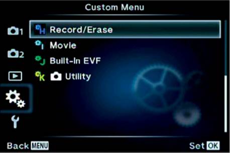
Figure 6.80: The opening menu for the H. Record/Erase functions
Quick Erase
The Quick Erase function gives you two ways to delete an unwanted image from the memory card: with explicit permission only, and immediately upon request. To erase an image you must display it on the camera monitor and press the Erase button on the back panel of the camera (looks like a red trash can).
At the time of deletion you can have the camera ask your permission first, or you can simply delete the image as soon as you press the Erase button. If you use the latter method (immediate erase), make sure you have selected the correct image to delete because the camera will truly delete it immediately.
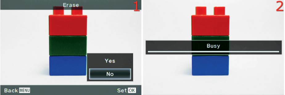
Figure 6.81A: Two types of image deletion: with permission (image 1) and immediate (image 2)
Figure 6.81A shows the screens you will see depending on how you configure this function. Image 1 shows the screen that asks permission before erasing the image. Image 2 shows what happens when no permission is required; the image will be immediately deleted when you press the Erase button.
Whichever method you choose affects erasing only one image at a time, and the image to be erased must be displayed on the camera monitor. Let’s consider how to choose an erase method for unwanted images.
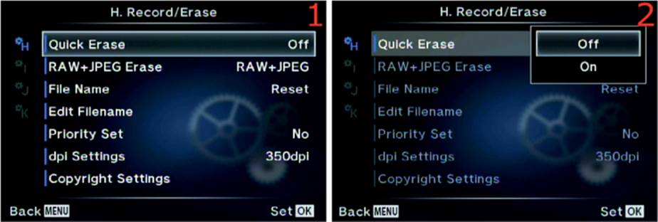
Figure 6.81B: Choosing erase with permission only, or immediate deletion upon request
Use the following steps to choose the single-image deletion method you prefer:
1. Select the Quick Erase function from the H. Record/Erase menu and scroll to the right (figure 6.81B, image 1).
2. From the Quick Erase menu (figure 6.81B, image 2) choose Off if you want the camera to ask for your explicit permission before it deletes an image when you press the Erase button. Choose On if you want the camera to instantly delete a displayed image as soon as you press the Erase button, without confirmation. The factory default is Off.
3. Press the OK button to Set your choice.
Settings Recommendation: At first I set my camera to erase an image immediately (Quick Erase set to On), then I accidentally deleted a precious image of my pregnant daughter. I had to go through the trouble of using an image recovery program to save the deleted image. This made me rethink immediate deletion. Now I use the permission required method (Quick Erase set to Off) because it displays the image with a Yes/No choice, giving me a moment longer to think before deleting an image.
If you delete a lot of images after you take them, the immediate deletion method (On) will save you considerable time. Just make sure you are deleting the correct image!
RAW+JPEG Erase
When you set the Record Mode for still pictures to JPEG+RAW, the camera creates one identical image in each format for every picture you take (Shooting Menu 1 > [Record Mode] > Still Picture).
That means two images are being stored for each picture, which uses up a lot of memory card capacity. Therefore, you will probably delete more images than normal to save space.
The RAW+JPEG Erase function lets you specify how to erase single image pairs. When you press the Erase button, do you want to erase both the RAW and JPEG file, just the RAW file, or just the JPEG file? You can choose. Let’s see how!
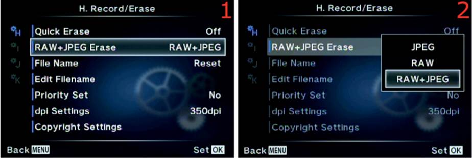
Figure 6.82: Choosing which image formats to erase with the Erase button
Use the following steps to choose how you want to erase RAW+JPEG image pairs:
1. Select RAW+JPEG Erase from the H. Record/Erase menu and scroll to the right (figure 6.82, image 1).
2. From the RAW+JPEG Erase menu, choose RAW+JPEG if you want to delete both images in the set when you press the Erase button (figure 6.82, image 2). Choose RAW to delete only the RAW (ORF) file and leave the JPEG file on the memory card. Or choose JPEG to delete just theJPEG image and keep the RAW file. The factory default for this setting is RAW+JPEG.
3. Press the OK button to Set your choice.
Note: This function is effective only when you are using single-frame playback, where one image at a time is displayed on the monitor or in the viewfinder. Also, if you use All Erase or Format from the Shooting Menu 1 > Card Setup function, all your images will be erased. The RAW+JPEG Erase function is for erasing a single image that is displayed on the camera monitor or in the viewfinder.
Settings Recommendation: Generally I leave this function set to the factory default of RAW+JPEG. If I want to delete an image, I normally don’t want to keep either of the formats.
However, if you are worried that the image may have some value later, or if you need to free up some memory card space while keeping at least one of the images, you can choose to delete just the RAW file or just the JPEG file when you press the Erase button.
File Name
The camera can create a running sequence of image file numbers so you can maintain a series of image numbers over time, even when a freshly formatted memory card is inserted. Alternatively, the camera can start over with a new sequence of image numbers when you insert a blank, formatted card.
Here are the two available settings and an explanation of how they work:
• Auto: The last four digits of the image file name run in a continuous series, even if you insert a blank, formatted memory card. File numbers are remembered from the previous card, and the file number on the next new image will be one higher than the previous number. In other words, if the final image on the memory card you last used had a file name ending in 0135 (e.g., P1010135.JPG), the next image you make will use 0136 (e.g., P1010136.JPG). This numbering sequence will continue until you have taken 9,999 images, then the file number sequence for the last four digits will roll back over to 0001. (See the next subsection, Edit Filename, for a clever way to manage images after you have exceeded 10,000 images with the camera.)
• Reset: Similar to the Auto mode, the camera will use the next available image number for any series of existing pictures it finds on a memory card. However, if you insert a blank, formatted memory card into the camera, it will forget the previous memory card sequence and start fresh with image numbers beginning at 0001. In other words, when the camera detects a blank memory card, it resets the numbering sequence back to 0001.
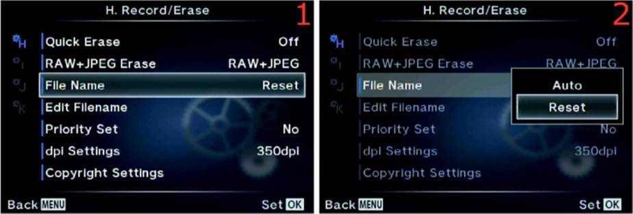
Figure 6.83: Choosing a file naming method (file number sequence)
Use the following steps to choose how you want the camera to handle file number sequences:
1. Select the File Name function from the H. Record/Erase menu and scroll to the right (figure 6.83, image 1).
2. A small up/down menu will appear with two choices: Auto and Reset (figure 6.83, image 2). Make your selection (refer to the previous list for an explanation of how each selection works).
3. Press the OK button to Set your choice.
Special Image Number Sequence Information
If you are interested in maintaining a continuous file number sequence for all future images with the camera using Auto, there are three important facts you should take note of. If you are using Reset instead of Auto, none of the following bulleted items matter because the camera will reset the file number sequence whenever it sees a blank memory card. If you use Auto, read these three bullets carefully:
• File folder management: The camera creates a file folder to hold your individual images when you first format or use a blank memory card. The image folder will be in the DCIM folder on the memory card and will have a name like 100OLYMP. If you exceed 9,999 images in the existing 100OLYMP folder, the camera will create a new folder with one higher number (e.g., 101OLYMP). Additionally, if you insert a memory card that has a folder containing an image with a file number ending in 9999, the camera will create a new folder in preparation for the next 9,999 images, even if there aren’t actually 9,999 images in the previous folder. Any time the camera sees the number 9999 on the end of an image, it will immediately create the next folder in the series and switch to the new folder.
• Accidentally disrupting an existing file number sequence: Since the camera remembers the last file number on the previous memory card that was inserted in the camera, if you insert a memory card with images that have a different sequence of file numbers, the camera will immediately remember the new sequence and disrupt your controlled sequence of file numbers. In other words, if the file number sequence you have been maintaining ends in 8995 and you insert a memory card with existing images that have a different number sequence (e.g., 3456), you will lose your controlled sequence. Therefore, if you want to keep a running sequence, never insert a memory card with foreign images on it. Always use an existing card in the image number series, or start with a blank, formatted card. If you accidentally insert a memory card that has a different sequence, you will need to reinsert a card that contains the old sequence and take a picture. If you cannot reinsert the old card, format a new card in the camera, copy the final image from the old sequence into the DCIM > 100OLYMP folder, then take a picture. That will reestablish the sequence.
• Using a file number sequence on a new camera: Be very careful to not insert any memory card with existing images from a different Olympus camera into a brand new E-M1. If you do, the camera will not start your number sequence at 0001 for the new camera. Instead, it may pick up the file number sequence from the other camera’s images. Always start your new camera’s file number sequence with a blank memory card, then follow the concepts in the previous bulleted item.
Settings Recommendation: I set my camera to Auto because I want to maintain a continuous file number sequence for my images. However, this means I have to be careful about using memory cards with foreign Olympus images on them. If you have no interest in maintaining a file number sequence, just set this File Name function to Reset and forget about it. The next subsection discusses how to start and maintain a file number sequence properly.
Edit Filename
File naming allows you to control the first four characters of the file name for each of your images shot with the sRGB color space, and three characters of the file name for images taken with the Adobe RGB color space. You can change the characters to any alphanumeric characters available on the camera.
The camera defaults to using the following file naming convention for your images:
• sRGB color space: P1011234
• Adobe RGB color space: _1011234
For the Adobe RGB color space, the camera adds an underscore to the beginning character position, instead of the default P, which allows you to use the next three characters for custom naming. For the sRGB color space, the camera does not add an underscore, so you can use all four character positions for custom naming.
I use this feature on my camera in a special way. Since the camera can count images in a file number sequence (see the previous File Name subsection) that continues from 0001 to 9999, I use the Edit Filename function to help me personalize my images. The camera cannot count images higher than 9,999. Instead, it rolls back to 0001 for the 10,000th image.
When I first got my camera, I changed the three default characters from P101 to DRY1 for the sRGB color space and DY1 for the Adobe RGB color space. The 1 tells me how many times my camera has passed 9,999 images, and DRY or DY are my initials, which helps me protect the copyright of my images in case they are ever stolen and misused.
Since the camera’s file number sequence counter rolls back to 0001 when you exceed 9,999 images, you need a way to keep from accidentally overwriting images from the first set of 9,999 images. I use the following method:
sRGB color space
|
• First 9,999 images: |
DRY10001 through DRY19999 |
|
• Second 9,999 images: |
DRY20001 through DRY29999 |
|
• Third 9,999 images: |
DRY30001 through DRY39999 |
|
• Fourth 9,999 images: |
DRY40001 through DRY49999 |
Adobe RGB color space
|
• First 9,999 images: |
_DY10001 through _DY19999 |
|
• Second 9,999 images: |
_DY20001 through _DY29999 |
|
• Third 9,999 images: |
_DY30001 through _DY39999 |
|
• Fourth 9,999 images: |
_DY40001 through _DY49999 |
My system only works up to 89,991 images (9,999×9). If you start your camera at 0 (DRY09999 or _DY09999), you can count up to 99,990 images.
If my method doesn’t work for your needs, you can use the three or four custom characters to classify your image names in all sorts of creative ways.
Let’s see how to assign custom characters.
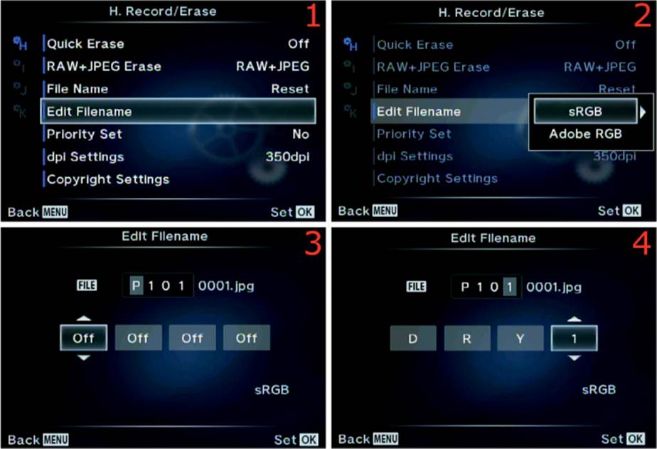
Figure 6.84A: Selecting four beginning file name characters for sRGB image files
Use the following steps to choose four new initial characters for image files created with the sRGB color space:
1. Select the Edit Filename function from the H. Record/Erase menu and scroll to the right (figure 6.84A, image 1).
2. Choose sRGB from the up/down menu and scroll to the right (figure 6.84A, image 2).
3. You will see the current file name for an sRGB file, which is shown as P101 0001.jpg in figure 6.84A, image 3. Choose a number or alphabetical character for each of the up/down menus that have Off displayed. Those four boxes represent the first four characters of the file name, which you can customize. Scroll up or down to select a custom character for each box. After you have chosen a value for one of the boxes, scroll right or left to select other boxes and change them too. In figure 6.84A, image 4, you can see that I have added my initials (DRY) to the first three custom positions and the number 1 to the fourth custom position. Now all my sRGB images will have a file name that begins with DRY1 (e.g., DRY10123.jpg).
4. Press the OK button to Set your choice.
Next, let’s consider how to change the custom characters for Adobe RGB files.
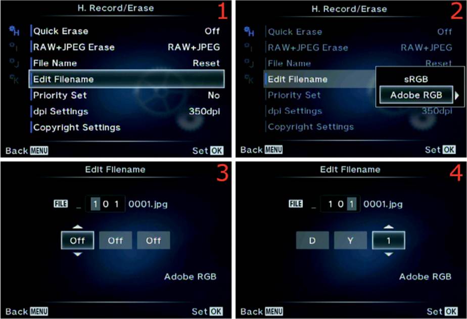
Figure 6.84B: Selecting three beginning file name characters for Adobe RGB image files
Use the following steps to choose three new initial characters for image files created with the Adobe RGB color space:
1. Select the Edit Filename function from the H. Record/Erase menu and scroll to the right (figure 6.84B, image 1).
2. Choose Adobe RGB from the up/down menu and scroll to the right (figure 6.84B, image 2).
3. You will see the current file name for an Adobe RGB file, which is shown as _101 0001. jpg in figure 6.84B, image 3. Choose a number or alphabetical character for each of the small up/down menus that have Off displayed. The first character is not available to customize for Adobe RGB files, unlike sRGB files. The first character will always be an underscore. The three boxes with Off displayed represent the next three characters of the file name, which you can customize. Scroll up or down to select a custom character for each box. After you have chosen a value for one of the boxes, scroll right or left to select other boxes and change them too. In figure 6.84B, image 4, you can see that the default underscore is in the first position, I added my initials (DY) to the second and third character positions, and I added the number 1 to the fourth custom position. Now all my Adobe RGB images will have file names beginning with _DY1 (e.g., _DY10123. jpg). The alignment of the three Off boxes seems to indicate that you can change the underscore, but you can’t. You can change only the second through fourth characters for the Adobe RGB color space.
4. Press the OK button to Set your choice.
Note: To change between the sRGB and Adobe RGB color spaces, see the function at Custom Menu > G. [JPEG Type]/Color/WB > Color Space. For detailed information on how to change the color space, see the previous subheading Color Space, under main section G, on page 407. Also, to prevent disrupting your carefully created file number sequence, review the subsection called Special Image Number Sequence Information at the end of the previous File Name function on page 413.
Settings Recommendation: At the beginning of this section we discussed how I use these three or four custom characters. You may want to use your initials or some other numbers or letters. Some people leave these characters at their default values. I recommend at least using your initials so you can easily identify images as yours. With my family of photographers it sure makes it easier for me! If you use my method, be sure to watch for the images to roll over to 9999 so you can rename the numeric custom character for the next sequence of 9,999 images.
Priority Set
When you decide to erase an image, as discussed in the previous Quick Erase function, you press the Erase button and are presented with a choice of Yes or No on a small menu.
The camera has many confirmation screens of this type, with Yes or No choices, and you can select which choice the camera defaults to when it asks for confirmation of various actions you want to perform.
Let’s see how to select a default value for Yes/No confirmation screens.
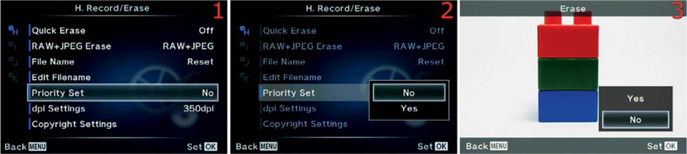
Figure 6.85: Default answer of Yes or No on confirmation screens
Use the following steps to choose a default value for when you request a change or deletion that requires a Yes or No answer:
1. Select the Priority Set function from the H. Record/Erase menu and scroll to the right (figure 6.85, image 1).
2. Choose Yes if you want the camera to always have Yes selected when a Yes/No confirmation screen appears, or choose No if you prefer No to be selected. The camera defaults to No (figure 6.85, image 2).
3. Press the OK button to Set your choice.
4. As an example, figure 6.85, image 3, shows the Erase confirmation screen, which you will see when you press the Erase button. Notice that the default is No when the screen first appears. Change the value to Yes in step 2 if you prefer that to be the default.
Note: The choice of Yes or No in step 2 affects many confirmation screens throughout the camera’s entire menu system. All screens with a Yes or No selection will obey the choice you make in step 2.
Settings Recommendation: I set my camera to Yes because I don’t want to make an additional choice when a Yes/No confirmation screen appears. I would rather it just default to Yes, and I can select No if I change my mind.
dpi Settings
With the dpi Settings function, you can select a default dpi (dots per inch) for your images. The dpi information is then embedded in the metadata of your images. This information is primarily for printers to control the dots per inch they use to make a print.
This value can be changed after the fact in computer software, such as Photoshop. You can therefore ignore this setting unless you want to print your images with a specific dpi setting. This is a useful setting for those who want to print directly from their camera or use DPOF (digital print order format) from a memory card.
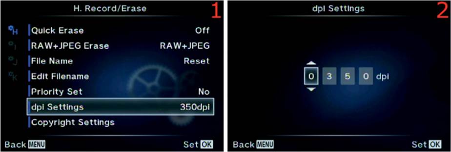
Figure 6.86: Choosing a dots per inch (dpi) setting for printing
Use the following steps to choose a default dpi value for your images:
1. Select the dpi Settings function from the H. Record/Erase menu and scroll to the right (figure 6.86, image 1).
2. Select a dpi value from the up/down menus in figure 6.86, image 2. You can choose from a range of 0001 (1 dpi) to 9999 dpi. The dpi setting will affect the printing resolution of the image on an inkjet printer or other types of printers. Many printing devices have a much more limited range than 0001 to 9999 dpi. The most common dpi for commercial printing in books and magazines is 300 dpi. Since the tiny dots a printer creates to make up an image varies among printer types, you may have to experiment with different dpi settings to see which looks best on your printer.
3. Press the OK button to Set your choice.
Settings Recommendation: I set my camera to 300 dpi because most of my work is printed at that dpi setting. If you rarely print your work, or if you prefer changing the dpi later in the computer, you can ignore this function. The quality (resolution) of the image will not be affected, regardless of how this setting is configured.
In my opinion, it is better to set this value in the computer just before the image is printed; therefore, I look at this function as a convenience setting.
Copyright Settings
The Copyright Settings function allows you to embed Artist Name and Copyright Name into the metadata of each image. With image theft so rampant on the Internet today, it is a good practice to put your personal or business name inside each image so it can be read on a computer. The government has recently been considering legislation for how to handle images that are orphaned. It isn’t a good idea to let your images be orphaned!
By adding your initials to the image file name with the Edit Filename function (previous subsection) and adding artist and copyright names with this Copyright Settings function, you are invisibly marking your images internally so that, at the very least, you can prove that you own the copyright to the image. An unscrupulous person could strip out the image EXIF information; however, because your image contains the information in the first place, stripping the image is illegal and can indicate that the image was stolen. This gives you greater ammunition for proving copyright infringement. In addition to using these safeguards, you can register the copyright for your images at http://www.copyright.gov/.
Now let’s examine how to add your personal information to your images.
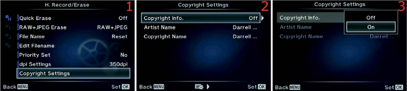
Figure 6.87A: Enabling Copyright Settings
Use the following steps to enable or disable the Copyright Settings function:
1. Select the Copyright Settings function from the H. Record/Erase menu and scroll to the right (figure 6.87A, image 1).
2. Choose Copyright Info and scroll to the right (figure 6.87A, image 2).
3. A small up/down menu will appear and offer you these choices: Off to disable the inclusion of your Artist Name and Copyright Name inside your images, or On to include that very important information (figure 6.87A, image 3).
4. Press the OK button to Set your choice.
Next let’s create the Artist Name and Copyright Name so it will be in the image metadata.
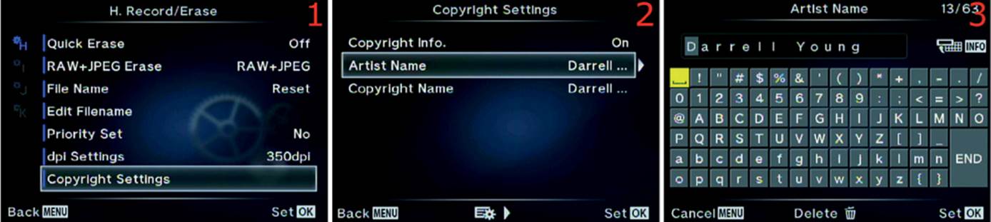
Figure 6.87B: Including your Artist Name in the EXIF information of an image
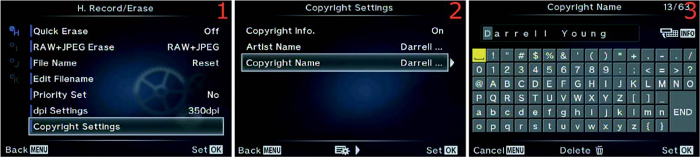
Figure 6.87C: Including your Copyright Name in the EXIF information of an image
Use the following steps to add your Artist Name and Copyright Name to future images. Both names are inserted the same way, so the following steps will work for both:
1. Select the Copyright Settings function from the H. Record/Erase menu and scroll to the right (figure 6.87B or 6.87C, image 1).
2. Choose Artist Name or Copyright Name from the menu and scroll to the right (figure 6.87B or 6.87C, image 2).
3. You will now see a screen with a grid of characters you can use for the Artist Name or Copyright Name (figure 6.87B or 6.87C, image 3). There is a maximum of 63 characters available for each name. Now follow these steps to create the name:
• Inserting a character: Use the Arrow pad to move the yellow highlight square around the gray grid of characters. When the character you want to use is under the yellow highlight, press the OK button to add the character to the line at the top of the screen, where you can see my name,Darrell Young, in the figures. Note that there is a space character at the top-left corner of the character grid (yellow highlighted).
• Fixing a mistake: If you make a mistake, simply press the Info button and the cursor will jump to the top where the already inserted characters are. Then you can scroll to the mistake and fix it. Position the cursor over the incorrect character and press the Delete button (red trash can). The incorrect character will disappear. Immediately press the Info button again and the cursor will jump back to the grid of characters so you can insert the correct character. When you select the correct character, the camera will insert it automatically and move the other characters to the right.
• Saving the name: When you are done creating the Artist Name or Copyright Name, move the yellow highlight cursor down to the bottom right of the character grid to the END selection. Highlight END and press the OK button to save the name.
Settings Recommendation: One of the first settings I change on my camera is this one. I want my name and initials all over the internal metadata of my images. This is a form of protection. At the very least, the fact that you own the original image with correct metadata proves that you took the image and own the copyright. Above all else, if you are concerned about your images, especially for commercial reasons, gather up a few hundred of them, put them on a CD, and register them at www.copyright.gov.
Custom Menu I. Movie
The I. Movie menu is composed of functions that set the Exposure modes for recording a movie, allow or disallow movie special effects, and determine how the sound recording system works while recording a movie.
We will start examining the functions by taking a look at the opening menu for the I. Movie functions in figure 6.88.
To enter the menu, select I. Movie from the Custom Menu and scroll to the right. There are six functions inside the I. Movie menu. Let’s consider each of them in detail.
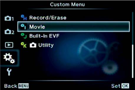
Figure 6.88: The opening menu selection for the I. Movie functions
[Mode Dial Movie] Mode
The Mode Dial on top of the camera has a Movie setting (figure 6.89A) that allows you to do more with video recording than when you simply press the Movie button.
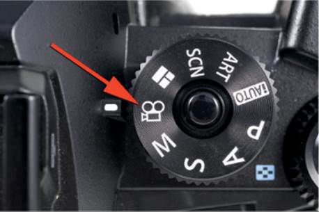
Figure 6.89A: The Movie setting on the Mode Dial
The Record Movie setting allows you to select one of the four primary exposure modes for video recording: Programmed auto (P), Shutter priority (S), Aperture priority (A), and Manual (M). Here is a description of the four modes:
• P: Programmed auto (P) mode allows the camera to select the optimal aperture according to how bright the subject is.
• A: Aperture priority (A) mode is used to control the depth of field in your video. This value must be set before you start the video recording. You cannot adjust the aperture while the camera is making a movie. Use the Rear Dial to adjust the aperture before the recording begins. During a video recording the camera will use the aperture you selected and will automatically select whatever shutter speed and ISO sensitivity are required to get a usable video.
• S: Shutter priority (S) mode is used to control motion blur and generally should be set to twice the frame rate of the movie; therefore, if you are using 1080p at 30 fps, the best shutter speed will be 1/60 second. However, you can adjust the shutter speed from as low as 1/30 second to 1/4000 second for special effects. You cannot change the shutter speed during video recording, so be sure to choose the setting you want before you start making your movie. Use the Rear Dial to adjust the shutter speed before the recording begins. During a video recording the camera will use the shutter speed you selected and will automatically select whatever aperture and ISO sensitivity are required to get a usable video.
• M: Manual (M) mode allows you to control both the shutter speed and the aperture for motion blur and depth of field control. You cannot adjust the aperture or shutter speed during the creation of a video. You must set the aperture and shutter speed you want to use before starting the recording. You will control the aperture with the Front Dial and the shutter speed with the Rear Dial. During a video recording the camera will use the aperture and shutter speed you selected, and you can also select an ISO range between 200 and 3200 before you start the video. Auto ISO is not used during video recordings in M mode; you have to adjust the camera for the correct lighting conditions before you start the video, and you must be careful not to move into areas where the light varies drastically to prevent over- or underexposure.
Note: Manual exposure compensation is not available in any video recording mode. In P, S, and A modes, the camera will automatically compensate for light variation. In M mode there is no way to compensate for light variance unless you are using a lens with an integrated manual aperture ring, which will allow you to open and close the aperture to allow for light changes.
Now let’s examine how to prepare the camera to record a video.
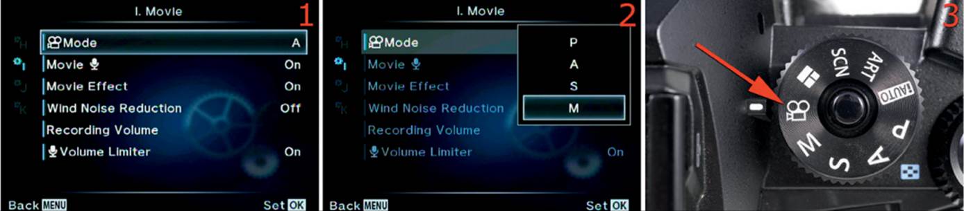
Figure 6.89B: Using various exposure modes when recording video
Use these steps to select an exposure mode before you record a video:
1. Select the [Mode Dial Movie] Mode function from the I. Movie menu and scroll to the right (figure 6.89B, image 1).
2. A small exposure mode menu will appear with four exposure modes: P, S, A, and M (figure 6.89B, image 2). Refer to the previous list, then choose one of the exposure modes and press the OK button to lock it in.
3. Set the Mode Dial to the movie camera icon (figure 6.89B, image 3). When you record the video, the E-M1 will use the exposure mode you selected in step 2. Before you start the video recording, configure the shutter speed, aperture, or ISO, depending on which exposure mode you selected (see list). The camera will record your video when you press the Movie button.
Settings Recommendation: If you are using a lens with an aperture ring, which will allow you to control the depth of field and the amount of light entering the camera, I suggest using the Manual (M) exposure mode. If you don’t have such a lens, and therefore no way to control the camera when the light level changes drastically, it may be best to use P, S, or A mode when you record a video. That way the camera can use Auto ISO sensitivity to control the exposure when the light varies greatly.
Movie [Mic]
This simple function allows you to enable or disable the camera’s built-in microphone (mic) or an external mic plugged into the mic port under the top rubber flap on the side of the camera.
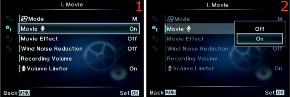
Figure 6.90: Enabling or disabling the camera’s mic input for recording movies
Use these steps to enable or disable the camera’s microphone for recording sound during video capture:
1. Select the Movie [Mic] function from the I. Movie menu and scroll to the right (figure 6.90, image 1).
2. A small menu will appear with Off and On selections for the mic input (figure 6.90, image 2). If you select Off the camera will not record any sound when you record a video. If it is left On (default), the built-in mic or an external mic plugged in to the mic port will record sound.
3. Press the OK button to Set the microphone to On or Off.
Settings Recommendation: I leave my mic set to On because I often record family videos with the camera’s built-in mic. Sometimes I even use an external mic mounted in the Hot shoe and plugged in to the external mic port. If you use the camera for commercial video and use an external digital recorder to capture high-quality sound, you may want to set this function to Off.
Movie Effect
The E-M1 offers five effects during movie recording. These effects are easily accessed with small buttons at the bottom of the Live View touch screen (figure 6.91A).
These five buttons enable the following effects, from left to right: Picture Mode, Old Movie, Multi-ghosting, Single-ghosting, and Digital zoom (figure 6.91A, bottom of screen). You can experiment with the effects before shooting video by placing the camera in Movie mode with the movie camera icon on the Mode Dial. The buttons will appear and you can review their effects before you record the movie. After you start to record a video, the buttons will still be active, and you can lightly touch them to enable or disable the effects.
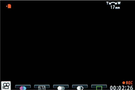
Figure 6.91A: Five Movie Effect buttons on the Live View touch screen
These Movie Effects are discussed in detail in the chapter Screen Displays for Camera Control, on page 121, for movie recording while using touch controls on the Live View screen.
The Movie Effect function allows you to enable or disable the touch buttons for using the Movie Effects. Let’s see how.
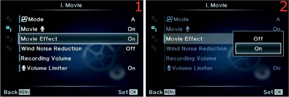
Figure 6.91B: Enabling or disabling the five Movie Effect touch buttons
Use the following steps to enable or disable Movie Effects:
1. Select the Movie Effect function from the I. Movie menu and scroll to the right (figure 6.91B, image 1).
2. A small menu will appear with Off and On options (figure 6.91B, image 2). Select On to enable the Movie Effects buttons or select Off to disable them. The camera defaults to On.
3. Press the OK button to Set your choice.
Settings Recommendation: I leave these Movie Effects enabled all the time. The first one, Picture Mode, allows me to shoot movies using the cool effects found in several of the Picture Modes and all of the Art Filters in the camera. This opens a wide selection of video special effects shooting. We consider each of these modes in the chapter called Screen Displays for Camera Control. Do not discount these Movie Effects because they are a great deal of fun and will make your videos look unique.
Wind Noise Reduction
When you are recording a video with the built-in mic or an external mic, sometimes the wind blowing on the mic will make a low-frequency rumbling noise that is quite objectionable.
It is usually not possible to completely eliminate strong wind noise, especially with an unprotected mic, but the objectionable sound can be reduced with a low-cut filter. The camera has one built in to the mic circuitry, and it can be set to various levels, including off.
Let’s examine how to configure the low-cut Wind Noise Reduction filter in your E-M1.
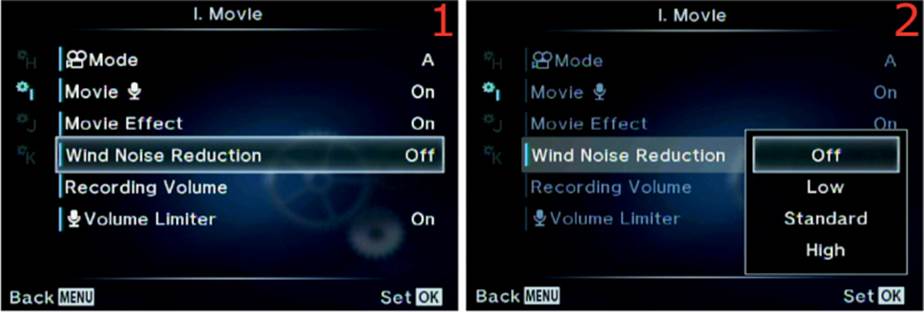
Figure 6.92: Enable or disable the camera’s Wind Noise Reduction filter
Use the following steps to set the Wind Noise Reduction level for video recording or turn it off:
1. Select the Wind Noise Reduction function from the I. Movie menu and scroll to the right (figure 6.92, image 1).
2. A small menu will appear with Off, Low, Standard, and High options (figure 6.92, image 2). Select Off to disable the Wind Noise Reduction filter, or choose Low, Standard, or High to select various levels of Wind Noise Reduction. The camera defaults to Off.
3. Press the OK button to Set your choice.
Settings Recommendation: This is an especially useful function if you mostly use the camera’s built-in mic. However, most people who are serious about video use a better external mic with special foam shielding around the sensitive mic head to prevent wind noise. I do not generally leave this setting enabled because a low-cut filter of this type tends to reduce some normal low-frequency sounds. However, if you are recording in a windy environment with the built-in mic, or if you are using an unprotected external mic, by all means use this filter. Even a small amount of wind blowing across the face of the camera can make a rumbling noise on the video soundtrack. You will need to experiment with the three levels of Wind Noise Reduction to see which level you prefer.
Recording Volume
With the Recording Volume function you can adjust the microphone sensitivity. There are separate controls for the built-in stereo mic, an external stereo mic plugged in to the mic port, and an external stereo device that produces sound (e.g., music from an iPhone) through the line-in feature of the mic port.
You can record sound to your video from any of these devices (one at a time), and the camera allows you to control the sound input types individually. Let’s see how.
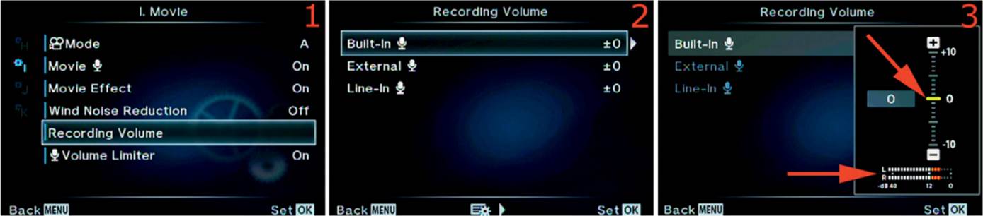
Figure 6.93: Set the Recording Volume level for the sound recording system
Use the following steps to set the Recording Volume or turn it off:
1. Select Recording Volume from the I. Movie menu and scroll to the right (figure 6.93, image 1).
2. Choose Built-in, External, or Line-in and scroll to the right (figure 6.93, image 2). All of these input types work exactly the same way, with the same controls; therefore, I will discuss only the first one, Built-in. Use the following steps for any of the input types to get similar results.
3. Figure 6.93, image 3, shows the control you will use to adjust the sensitivity of the two microphone types (or Line-in). There is a sliding indicator scale with a yellow bar (top red arrow) that you move up or down by rotating the Rear Dial or pressing the up and down keys on the Arrow pad. You can adjust the mic sensitivity over a 20-level range from +10 to –10, and the adjustment value will appear in the gray box that contains a 0 in image 3. The best way to do the adjustment is to watch the sound level on the L (left) and R (right) scale at the lower red arrow, which indicates the stereo sound input. You can see in image 3 that both the left and right channels of my Built-in mic are in the red, which means the sound is overpowering the mic and there is some sound distortion instead of clear sound. As I watch the average sound level, I may decide to dial back the sound input by moving the yellow bar down toward –10 until the L and R sound bars are no longer in the red. If the sound barely registers on the L and R scales, I might increase the mic sensitivity (turn up the gain) by moving the yellow bar up toward the +10 value. Again, this works the same way for all three types of input: Built-in, External, and Line-in.
4. After adjusting the sensitivity for the input type you are using, press the OK button to Set the sensitivity level.
Settings Recommendation: This is a powerful function that allows you to set different sensitivities for the built-in mic, an external mic, or an external sound device, such as an iPhone, iPod, or iPad that is playing music. The camera does a pretty good job of managing the sound level for both mic types, so I rarely use this function. However, when I feed music from my iPhone into the camera, I find that I have to turn the volume down very low on the iPhone and carefully watch the L and R sound level scales to make sure I don’t overpower the Line-in port. With a little experimentation and adjustment, you can play your favorite music directly into your camera for videos that need no other type of sound. I bet none of your friends’ cameras can do that. Make them jealous!
[Mic] Volume Limiter
When you capture sound of any type while you record a video, the sound may suddenly become overpoweringly loud.
Maybe you are recording a basketball game and the player SCORES! The crowd erupts with fist-shaking screams of delight and generates a sudden explosion of noise that sets off car alarms outside the auditorium. Do you want the energetic yelling and foot stomping to be recorded as distorted crackling in the sound of your video? No? Simply leave the [Mic] Volume Limiter function set to its default of On. The camera will sense the sudden blast of loud sound and limit the input to the camera, and hopefully save your video from requiring extensive sound editing later. Let’s see how to enable or disable the [Mic] Volume Limiter.
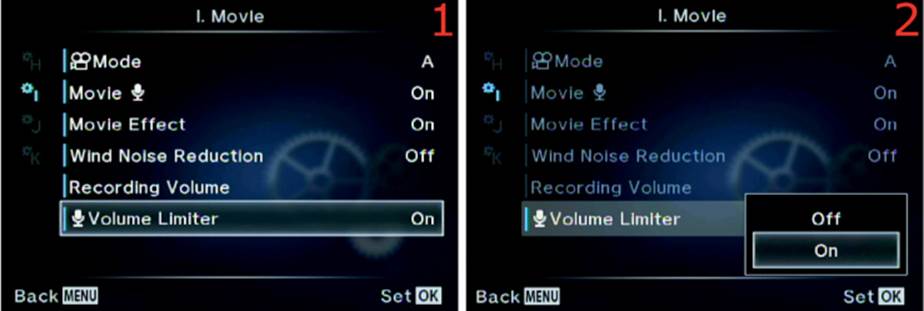
Figure 6.94: Limit the maximum recording volume for loud sounds
Use the following steps to enable or disable the [Mic] Volume Limiter for video recording:
1. Select the [Mic] Volume Limiter function from the I. Movie menu and scroll to the right (figure 6.94, image 1).
2. A small menu will appear with Off and On choices (figure 6.94, image 2). Select Off to disable the [Mic] Volume Limiter or On (default) to enable it.
3. Press the OK button to Set your choice.
Settings Recommendation: It is a good idea to leave this function enabled at all times. Although you can control sound most of the time, sometimes sudden noises can happen too fast to manually compensate for them. To preserve the sound quality in your video, it may be a good idea to let the camera automatically react to overpowering sound.
Custom Menu J. Built-In EVF
The J. Built-In EVF menu is primarily composed of functions that manage the electronic viewfinder (EVF) behind the eyepiece of the camera. It provides settings for things like the style of the EVF, overlays that are displayed on the EVF, how the eye sensor works, and the brightness and color balance of the EVF.
We will start examining the functions by taking a look at the opening menu for the J. Built-In EVF functions in figure 6.95.
To enter the menu, select J. Built-In EVF from the Custom Menu and scroll to the right. There are six functions inside the J. Built-In EVF menu. Let’s consider each of them in detail.
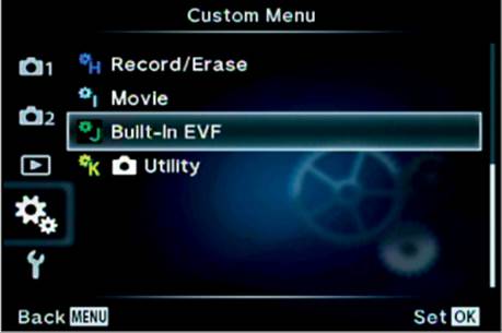
Figure 6.95: The opening menu for the J. Built-In EVF functions
Built-in EVF Style
The camera offers three Built-in EVF Styles, as shown in figure 6.96A. Style 1 and Style 2 have a retro film camera look. Style 3 is the factory default, which looks more modern. Style 3 imitates the layout of the rear monitor, so many people prefer this Style.
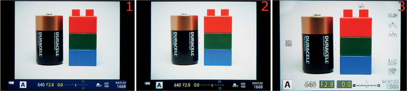
Figure 6.96A: EVF Styles 1, 2, and 3
Styles 1 and 2 provide shooting information in a band at the bottom of the EVF. Style 1 has a blue band with yellow and white characters. Style 2 has a dark gray (almost black) band with yellow and white characters. Style 3 is the default. It has bright white characters with exposure information in yellow. Notice in the figure that Style 3 provides a little more magnification of the subject, making it somewhat easier to see.
Let’s examine how to select one of the Styles.
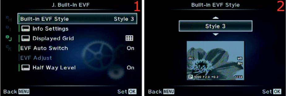
Figure 6.96B: Choosing an EVF Style
Use these steps to select one of the EVF Styles:
1. Select Built-in EVF Style from the J. Built-In EVF menu and scroll to the right (figure 6.96B, image 1).
2. Use the up/down menu to select one of the three Styles. Refer to figure 6.96A to choose your favorite (figure 6.96B, image 2).
3. Press the OK button to Set your choice.
Settings Recommendation: I generally leave my camera set to the factory default of Style 3. I like the larger view of the subject in the viewfinder and having the monitor and viewfinder look the same. However, before you make a final decision about which EVF Style you will use, examine the rest of the functions in the J. Built-In EVF menu. Some of the upcoming functions work differently when you use Styles 1 and 2.
Info Settings
Depending on which Style you chose for the Built-in EVF Style, you can have the EVF display things that are normally seen only on the rear monitor. The EVF can display a Live Histogram, show a Highlight&Shadow screen, present a Level Gauge, or allow a sparse Basic Information screen.
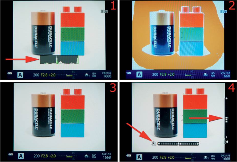
Figure 6.97A: The four Info Settings types: Live Histogram (image 1), Highlight&Shadow (image 2), Basic Information (image 3), and Level Gauge (image 4)
While choosing Info Settings, remember that the Info overlays apply to the EVF, not the Live View monitor. To see all the selected Info Settings, you must look into the viewfinder while pressing the Info button repeatedly.
Let’s examine what each of the three EVF Styles display, using the screen overlays in figure 6.97A, images 1–4, as examples:
• Style 1: This Style offers a blue band at the bottom with exposure information displayed similarly to a retro film camera. You can select several overlays by pressing the Info button repeatedly. The camera offers Live Histogram (image 1), Highlight&Shadow (overexposed areas turn orange, image 2), Basic Information (image 3), and Level Gauge (image 4).
• Style 2: This Style is virtually identical to Style 1, except it uses a black band at the bottom of the EVF instead of a blue band. See Style 1 in the previous bullet for details about the displays.
• Style 3: This Style makes the EVF perform like a smaller version of the monitor on the back of the camera. The EVF and monitor will generally look identical. Style 3 offers all the features of Styles 1 and 2 with the exception of the Highlight&Shadow (orange overexposure) mode infigure 6.97A, image 2.
Now let’s examine how to select which Info Settings you want to use in the EVF.
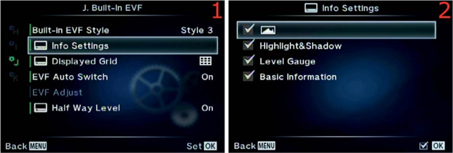
Figure 6.97B: Choosing an Info Settings type
Use these steps to select the Info Settings you want to use on the EVF:
1. Select Info Settings from the J. Built-In EVF menu and scroll to the right (figure 6.97B, image 1).
2. You can make four choices on the Info Settings screen (figure 6.97B, image 2). [Live Histogram], Level Gauge, and Basic Information are checked by default. Highlight& Shadow is not checked and is of no use if you are using Style 3. However, if you are using either Style 1 or 2, you may want to check the Highlight&Shadow setting so it will show blown-out (overexposed) areas in the EVF. To check or uncheck an item, highlight it and press the OK button. When an item is checked, each Info Setting will appear on the EVF when you press the Info button repeatedly.
3. Press the Menu button to return to the main menu when you are done.
Settings Recommendation: I check all the available Info Settings in case I decide to use an EVF Style that works with that setting. I don’t see a problem with checking all of them, so why not?
Displayed Grid
The camera can display a series of five grid types as overlays in the EVF, as seen in figure 6.98A. Image 1 is Off, and the other five grid types are shown in images 2–5.
The five grid types will help you align your image correctly for various types of photography. The grid overlays are available only when you use EVF Styles 1 or 2 (not Style 3).
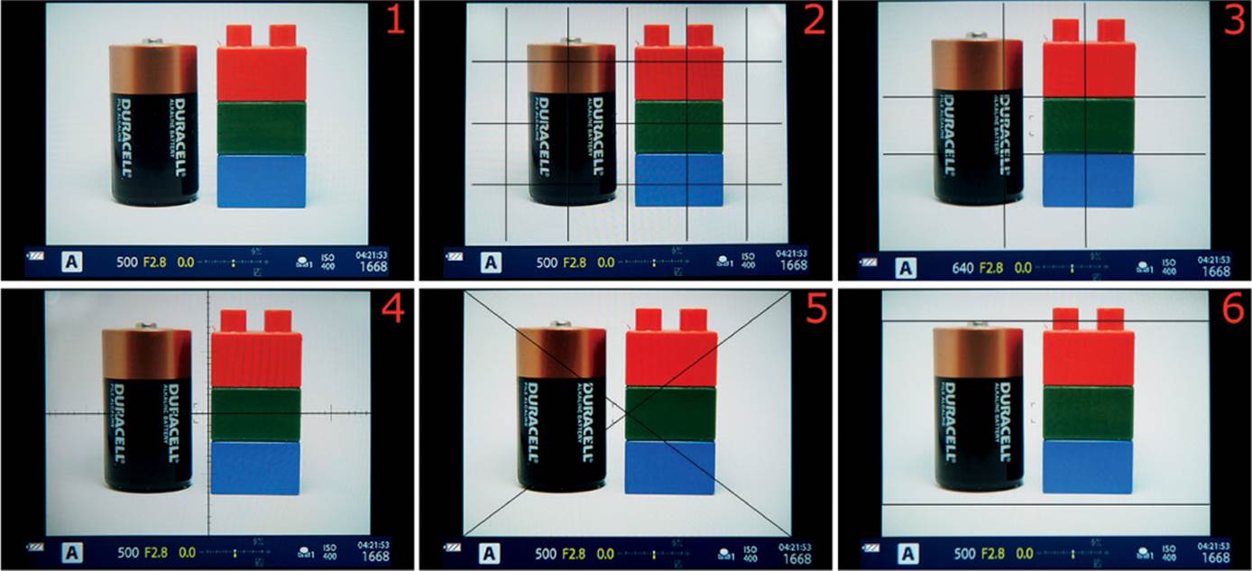
Figure 6.98A: The default EVF screen and five Displayed Grid types
Note: The Displayed Grid function provides no grid displays for EVF Style 3, but all is not lost. You can still use all five grid types with Style 3 by choosing one of the grid types from Custom Menu > D. Disp/[Sound]/PC > Displayed Grid instead of using this function.
When you choose a grid type, remember that the grids apply to the EVF, not the Live View monitor. To see the grid, you must be looking into the viewfinder.
Let’s examine how to select a Displayed Grid type for EVF Styles 1 and 2.
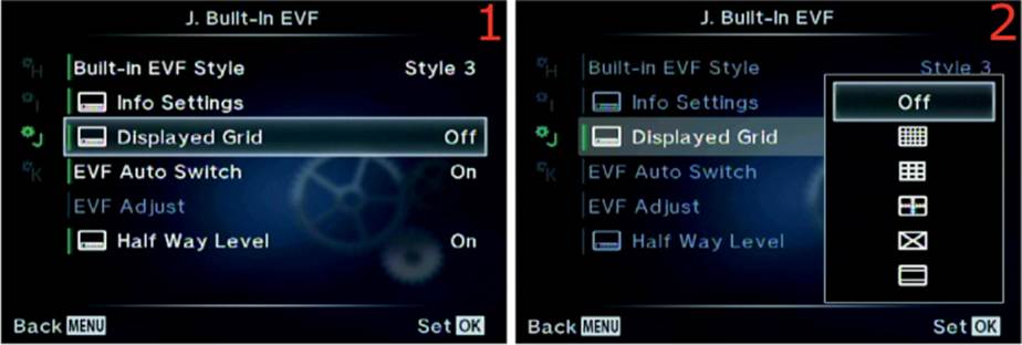
Figure 6.98B: Choosing a Displayed Grid type for EVF Styles 1 and 2 (only)
Use these steps to select a Displayed Grid type when you are using EVF Styles 1 and 2:
1. Select Displayed Grid from the J. Built-In EVF menu and scroll to the right (figure 6.98B, image 1).
2. Use the menu to select one of the five grid types or Off (figure 6.98B, image 2). Refer to figure 6.98A to choose your favorite.
3. Press the OK button to Set your choice.
Settings Recommendation: In figure 6.98A, image 2, you can see that I selected the first Displayed Grid type (directly under Off). I like this grid because it helps me align the horizon when I am shooting landscapes, and it also makes it easier to shoot buildings when I’m walking around town photographing architecture. There is a grid type to suit most photo needs, so experiment with each of them to see which you prefer, if any.
Remember that the grid types from this function apply only to EVF Styles 1 and 2. You can use the same grid types for Style 3 by choosing a grid type from Custom Menu > D. Disp/[Sound]/PC > Displayed Grid.
EVF Auto Switch
The camera has a small eye detector built in to the right side of the viewfinder, which is why the rubber viewfinder attachment has such an odd shape. If you look closely you will see two tiny lenses at the bottom right of the viewfinder. These lenses detect when anything gets close to the viewfinder, then it closes the EVF Auto Switch and enables the internal EVF, which turns the rear monitor off.
If you prefer to use the rear monitor for all your pictures, you can disable the EVF Auto Switch. Then the camera will ignore your eye or anything else that gets close to the view-finder and leave the rear monitor active for shooting pictures.
Let’s see how to enable or disable the EVF Auto Switch (eye sensor).
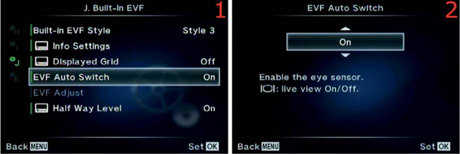
Figure 6.99: Enabling or disabling the EVF eye sensor
Use these steps to enable or disable the viewfinder eye detector:
1. Select EVF Auto Switch from the J. Built-In EVF menu and scroll to the right (figure 6.99, image 1).
2. Use the up/down menu to select either On or Off for the eye sensor (figure 6.99, image 2). The On setting enables the Live View Monitor until the camera senses something close to the Viewfinder eyepiece, then it enables the EVF and disables the Monitor. The Off setting uses the Live View Monitor only and turns off the eye sensor. If this function is set to Off, you can manually switch to the EVF by pressing the LV button at the left of the Viewfinder, which will toggle the camera between the EVF and the rear Monitor.
3. Press the OK button to Set your choice.
Note: If you hold down the LV button to the left of the viewfinder eyepiece for about two seconds, the camera will open the EVF Auto Switch menu directly, then you can select On or Off to enable or disable the eye sensor very quickly.
Settings Recommendation: I prefer to use the EVF for most of my photography. However, I do find the Live View monitor to be quite handy for casual photography and for macro shooting. Therefore, I usually leave the EVF Auto Switch set to On so the camera will sense my eye approaching the viewfinder and automatically turn on the EVF and turn off the monitor. However, I shoot macros with the Live View monitor, and I sometimes get my hand too close to the viewfinder and the monitor goes off, causing me to lose sight of my subject. When that happens, I may temporarily disable the EVF Auto Switch (set it to Off) so I can keep the Live View monitor active at all times.
EVF Adjust
The E-M1 automatically controls the brightness and color balance (hue) of the EVF, depending on the ambient light conditions. If you want to control the brightness and color balance of the EVF yourself, you can use this function to do so. Let’s see how.

Figure 6.100A: Enabling or disabling EVF Auto Luminance
Use these steps to enable or disable EVF Auto Luminance:
1. Select EVF Adjust from the J. Built-In EVF menu and scroll to the right (figure 6.100A, image 1).
2. Choose EVF Auto Luminance from the EVF Adjust screen and scroll to the right (figure 6.100A, image 2).
3. Use the up/down menu to select either On or Off (figure 6.100A, image 3). If you select On (default), the camera will adjust the EVF brightness and hue automatically. If you choose Off, you can use the EVF Adjust setting (second menu item in image 2) to control the EVF brightness and hue manually. Examine the steps for figure 6.100B to use the EVF Adjust setting for manual EVF brightness and hue control.
4. Press the OK button to Set your choice.
Next let’s see how to adjust the EVF brightness and hue manually instead of letting the camera control it automatically.
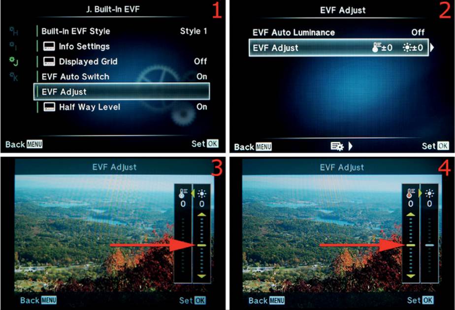
Figure 6.100B: Setting the EVF brightness and color balance
Use these steps to manually control the brightness and hue of the EVF screen. While you make these adjustments, remember that they apply to the EVF, not the Live View monitor. To make the adjustments shown in figure 6.100B, images 3 and 4, you must be looking into the viewfinder to see the screens:
1. Select EVF Adjust from the J. Built-In EVF menu and scroll to the right (figure 6.100B, image 1).
2. Choose EVF Adjust from the EVF Adjust screen and scroll to the right (figure 6.100B, image 2).
3. You will now see a screen in the EVF that displays the last picture you took or the last picture you viewed from the memory card. The picture is overlaid with two adjustment sliders on the right: one for brightness and one for hue or color temperature (figure 6.100B, image 3). The adjustment for brightness is on the far right side of the EVF screen (image 3, red arrow). You can use the keys of the Arrow pad to scroll up or down to adjust the brightness of the EVF over a range of 14 levels. You can move the yellow bar at the point of the red arrow up seven levels (+7) or down seven levels (–7), which brightens or darkens the backlight of the EVF screen.
4. When you are done, scroll to the left with the left key of the Arrow pad to adjust the hue (color temperature) of the EVF (figure 6.100B, image 4). Notice at the point of the arrow that the hue setting is 0. You can adjust the hue up seven levels (+7) or down seven levels (–7). An upward adjustment makes the hue shift toward blue (cooler), and a downward adjustment makes the hue shift toward red (warmer). Adjust the EVF color temperature until it seems right to you.
5. Press the OK button to Set your EVF brightness and hue choices.
Note: The EVF brightness and hue settings are for comfort only and do not affect the brightness or hue of the images you create. The brightness and color temperature of your pictures are controlled by the exposure and white balance settings.
Settings Recommendation: I normally leave my camera set with EVF Auto Luminance set to On. This lets the camera control the brightness and hue of the monitor, similar to how my iPhone adjusts when the ambient light changes. I have found the camera’s choices to be satisfactory, and the automatic control is quite convenient.
However, if you are shooting in a controlled studio environment with careful color matching, you may want to adjust the EVF until it looks best for your light source.
Half Way Level
If you are using Built-in EVF Styles 1 and 2, the camera displays a small Half Way Level at the bottom of the EVF. The Half Way Level is not available with Built-in EVF Style 3.
The level is called a Half Way Level because it activates when you press the Shutter button half-way down. When the level appears, it replaces the –/+ exposure indicator at the bottom of the EVF screen. Figure 6.101A shows the Half Way Level (red arrow) with the camera tilted off axis from the subject.
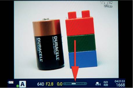
Figure 6.101A: Using the Half Way Level
When the camera is off level horizontally, a series of white bars will extend to the left or right of the center of the scale in the opposite direction of the camera body rotation. If you rotate the camera more than a few degrees horizontally, the scale will run out of white bars, and an orange arrow will appear above the scale to indicate the camera cannot register any more degrees of rotation.
When the camera is exactly level horizontally, the center bar and the two up/down arrows above the center bar will turn green.
Let’s examine how to enable or disable the Half Way Level.

Figure 6.101B: Enabling or disabling the Half Way Level
Use these steps to enable or disable the Half Way Level:
1. Select Half Way Level from the J. Built-In EVF menu and scroll to the right (figure 6.101B, image 1).
2. Use the menu to select On or Off to enable or disable the Half Way Level (figure 6.101B, image 2).
3. Press the OK button to Set your choice.
Settings Recommendation: I leave this level enabled in case I decide to use a different EVF Style than my normal Style 3. However, if I want to use a real level, I simply use the camera’s main Virtual level. It is available when you press the Info button until the level appears on the monitor or in the EVF. The Virtual level shows left and right rotation along with forward and backward rotation.
Custom Menu K. Utility
The K. Utility menu is composed of nine functions that don’t readily fit into one of the other Custom Menus. We will start examining the functions by taking a look at the opening menu for the K. Utility menu in figure 6.102. This is the last menu system in the group of Custom Menus.
To enter the menu, select K. Utility from the Custom Menu and scroll to the right. There are nine functions inside the K. Utility menu. Let’s consider each of them in detail.
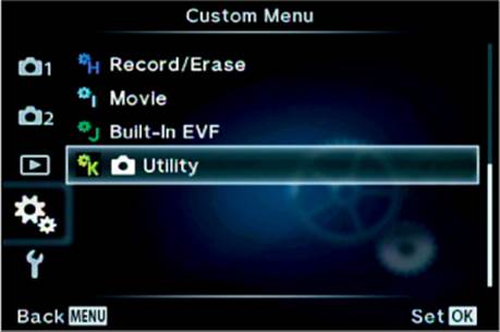
Figure 6.102: The opening menu for the K. Utility functions
Pixel Mapping
The E-M1 allows you to run a self-check on the camera sensor and image processing functions. When your camera was first manufactured, one of the final steps before the camera was released was the Pixel Mapping process. Why?
All digital cameras suffer from two maladies, both initially and over time:
• Dead pixels: A dead pixel is a photosite on the sensor that has become unresponsive. It will appear as a tiny black spot in the same place on every image unless it is mapped out.
• Stuck pixels: A stuck pixel is a photosite that reports full exposure regardless of the actual exposure. This means the pixel will always appear as one color, usually red or white, at the same place in every image. It should be mapped out.
Because the E-M1 is an advanced camera, you can run a similar Pixel Mapping function as the one used by Olympus technicians. You don’t want black, white, or colored spots in all your images, so you should run the Pixel Mapping function as needed to remap the dead and stuck pixels on your camera sensor.
Olympus recommends that you run the Pixel Mapping function at least once a year. However, if you detect dead or stuck pixels in your images when they are viewed at 100 percent on your computer monitor, you can run the Pixel Mapping function and map the bad photosites out of future images. The camera will interpolate data from surrounding pixels to fill in what should be captured at the mapped-out pixel, preventing image degradation that would otherwise be caused by using the Pixel Mapping function.
Mapping the bad pixels takes about 20 seconds, and you will hear the camera make some odd clicking noises as it tests and maps the entire sensor and image processing system.
Let’s see how to run the Pixel Mapping function.
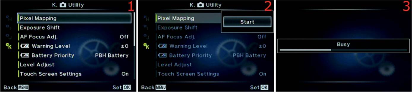
Figure 6.103: Remapping the sensor pixels
Use these steps to run the Pixel Mapping function to tune up your sensor and image processing system:
1. Select Pixel Mapping from the K. Utility menu and scroll to the right (figure 6.103, image 1).
2. Choose Start from the menu and press the OK button to begin mapping the pixels (figure 6.103, image 2).
3. During the Pixel Mapping process, you will hear various clicks from the camera over a period of about 20 seconds. While the camera is working you will see a Busy indicator on the screen (figure 6.103, image 3). When Pixel Mapping is complete, the camera will return to the main menu.
Note: In addition to dead and stuck pixels, you may have heard of hot pixels. A hot pixel is not a dead or stuck pixel, and the Pixel Mapping function is not designed to deal with them specifically. Hot pixels are photosites on the sensor that have become overheated due to long exposures. They will appear in images as various incorrect colors. As the camera cools, the hot pixels will cool off and return to normal. Use the Custom Menu > E. Exp/[Meter]/ISO > Noise Reduct. function to deal with hot pixels. The camera should not map out hot pixels because they move around on the sensor.
It is not a good idea to run the Pixel Mapping function after you take a lot of exposures or a long exposure, especially when you are shooting in a warm environment. You don’t want the camera to map out pixels that are useful in normal exposures. Therefore, it is best to run Pixel Mapping before you start shooting images for the day. At the very minimum, allow the camera to cool down for at least one minute after you take pictures, and significantly longer if the camera is warm to the touch.
Settings Recommendation: This is a powerful and useful function for photographers who cannot afford to have spots on their pictures. I do not indiscriminately run this function. I run it at least once per year or more often if I see dead or stuck pixels. All digital cameras will lose a few pixels over time, although not enough to affect the image, even after many years of use. However, aren’t you glad that Olympus gave you a Pixel Mapping function so you can take care of the problem yourself instead of having to send your camera in for service?
Exposure Shift
If you think one of your camera light meters (Digital ESP, Center weighted, Spot) needs a little fine-tuning, you can use this function to set up a semipermanent exposure compensation for individual light meter types.
For instance, if you usually shoot with the Digital ESP meter and you want the meter to add a half stop of exposure beyond the default, you can set it up with this function.
The camera allows you to fine-tune each light meter type in 1/6 stop (1/6 EV step) increments, up to one full stop over- or underexposed. In figure 6.104, image 4, you can see that I added 1/2 stop (+3/6). Let’s see how to accomplish Exposure Shift fine-tuning.
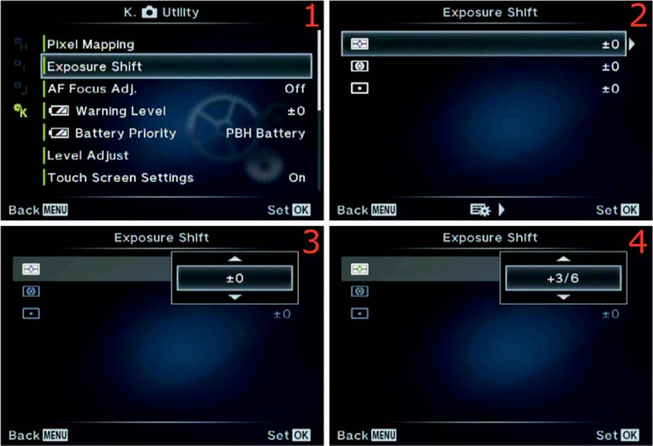
Figure 6.104: Fine-tuning the camera’s exposure meters
Use these steps to set up a semipermanent Exposure Shift on any or all of the three light meter types:
1. Select Exposure Shift from the K. Utility menu and scroll to the right (figure 6.104, image 1).
2. The top meter selection is the Digital ESP meter. The second meter type is the Center weighted meter, and the third meter type is the Spot meter (figure 6.104, image 2). Let’s use the Digital ESP meter as an example of how to set up an Exposure Shift of 1/2 stop (+3/6). The process is the same for all meter types, so you can use these steps for whichever meter you want to fine-tune. Choose the meter you want to modify and scroll to the right.
3. In figure 6.104, image 3, the Digital ESP meter is selected, the Exposure Shift menu is open, and the camera is currently set to no Exposure Shift (±0). Use the keys of the Arrow pad to select from +1/6 to +1 stop of Exposure Shift in 1/6 stop increments.
4. In figure 6.104, image 4, you can see that +3/6 EV steps (1/2 stop) is selected. The camera will add 1/2 stop of exposure compensation and mildly overexpose the image.
5. After you have selected how much you want to shift the exposure, press the OK button to lock in the Exposure Shift setting. Repeat these steps for any other meter type that you want to adjust.
Note: The Exposure Shift function is a form of exposure compensation. It is applied semipermanently; that is, it stays in place until you go back to the Exposure Shift function and remove the shift value. When you shift the exposure for any of the light meters, you may find that you do not have the normal range of exposure compensation after you adjust the meter.
Also, you will not see the effects of the Exposure Shift in the EVF or on the rear monitor, although you will be able to detect it in the image histogram.
Settings Recommendation: I have found that the exposure meters in the E-M1 are very accurate, and I am quite satisfied with their performance. However, you may be shooting a style of photography that easily fools your light meter. In that case, experiment with this function to see if it will help overcome the exposure problem. Don’t forget that Exposure Shift is in place or you may find that your images are regularly over- or underexposed.
AF Focus Adj.
Some lenses have a tendency to not focus exactly where they should. The lens may focus a little in front of or behind the point where you want the focus to be. A lens may focus well on one camera body and not so well on another. It is almost as if some lenses have a personality.
If you have a lens that acts like that, you may need to have it repaired. However, if the problem is minor, you can use the AF Focus Adj. function to fine-tune the focus of an individual lens, or even all lenses that you mount on your camera.
Let’s examine how to work with the focus adjustment system.
Setting an AF Focus Adjustment for All Lenses
If you think your camera has a tendency to focus incorrectly with all lenses you mount on it, you may need to have your camera repaired. In the meantime, though, you may have to shoot some important pictures and want to fine-tune the camera so all lenses focus more accurately.
Experiment first and determine whether you need to push the focus away from the camera or pull it back in to increase sharpness. That is the purpose of the Default Data subfunction. Let’s see how to use it.
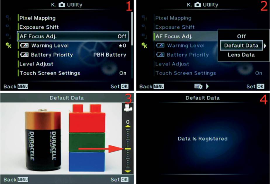
Figure 6.105A: Adjusting the focus for all lenses you mount on your camera
Use these steps to adjust the focus for all lenses you mount on your camera:
1. Select AF Focus Adj. from the K. Utility menu and scroll to the right (figure 6.105A, image 1).
2. Highlight Default Data on the menu and scroll to the right (figure 6.105A, image 2).
3. In figure 6.105A, image 3 (red arrow), you can see the adjustment indicator. You can move this yellow bar up and down with the keys on the Arrow pad over a range of 40 increments (+20 to –20). Moving this bar up moves the focus forward by up to 20 increments; moving it down moves the focus backward by up to 20 increments. The number at the top of the indicator is 0 in the figure, but it will change as you move the yellow bar to a plus or minus value. Choose the amount of focus adjustment you need to use.
4. Press the OK button to Set your choice, then a screen will appear that says Data Is Registered (figure 6.105A, image 4). Test the focus and readjust as necessary by repeating steps 1–3.
Now let’s examine how to adjust the focus for just one lens. All other lenses will focus normally.
Setting an AF Focus Adjustment for an Individual Lens
If you have a lens that is not focusing correctly and do not want to send it in for repair, you may be able to use the Lens Data subfunction to adjust the focus for only that lens and make it more accurate. You can maintain a custom focus adjustment for up to 20 separate lenses. Let’s see how to adjust the focus for a single lens.
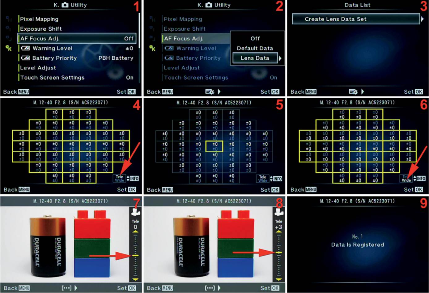
Figure 6.105B: Adjusting the focus for a single lens
Use these steps to adjust the focus for a single lens that is mounted on the camera:
1. Select AF Focus Adj. from the K. Utility menu and scroll to the right (figure 6.105B, image 1).
2. Highlight Lens Data on the menu and scroll to the right (figure 6.105B, image 2).
3. Notice in figure 6.105B, image 3, that there is a single selection, Create Lens Data Set. Later, after you have adjusted at least one lens, the lens name will appear in a list on this screen. In our example there are no adjusted lenses to show, so scroll to the right.
4. As soon as you scroll to the right, you will see the screen in figure 6.105B, image 4. This screen shows the 37 adjustable focus points in a highlighted grid. You can adjust all of the points at the same time for this lens, or you can adjust a single AF point. If you scroll to the left or right with the keys on the Arrow pad, you will see that only one focus point will be highlighted (figure 6.105B, image 5); the other 36 points have been deselected. In figure 6.105B, images 4 and 6 (red arrows), the words Tele and Wide are displayed. Press the Info button to move between Tele andWide so you can adjust the lens for the corresponding ends of the zoom range. When you toggle between Tele and Wide you can see that the ±0 settings in each square of the grid change from the top to the bottom. This indicates that you can have separate adjustments for the Tele andWide settings. To make the actual adjustment, you must choose one of the setting types, as shown in images 4–6. When the type of adjustment you want to make is displayed on the screen, press the OK button.
5. Now you will see the screen shown in figure 6.105B, image 7. This screen allows you to adjust the focus forward or backward for the AF points you selected in images 4–6. You can adjust the focus forward up to 20 increments (0 to +20) by scrolling up with the Arrow pad key. The yellow bar at the point of the red arrow in image 7 will move up or down as you scroll. Move the yellow bar down with the Arrow pad key to pull the focus backward by up to 20 increments (0 to –20). Image 8 shows that I have moved the bar (and focus) by +3 increments in a forward position, which means the lens now has a small amount of front focus dialed in. Also notice that the word Tele is displayed just above the indicator, signifying that I am adjusting focus only for the telephoto end of the zoom lens. Adjust the indicator up or down to move the focus forward or backward. When you have moved the bar to where you want it for both the Tele and Wide positions, you are ready to test the adjustment. Press the OK button to lock in the new adjustment, and take a few pictures to test your settings. Use the information in the upcoming subsection if you want to change an existing adjustment for greater accuracy.
6. When you have saved the adjustment by pressing the OK button, a screen will appear that says Data Is Registered, along with a lens number assignment (No. 1) (figure 6.105B, image 9). You can edit the lens number, as discussed in the next subsection.
Note: You will need to adjust each lens individually with this subfunction. If you want to fine-tune the focus on more than one lens, the camera will remember each lens separately. It will create a numbered list of up to 20 lenses that have been adjusted, and you can edit the adjustment for each lens.
You may have noticed that the AF point grid presented to you in this function does not contain the full 81 AF points you normally see when you use a Micro Four Thirds lens. Instead, the grid resembles the 37-point grid you see when you use an older Four Thirds lens. I’ve consulted with upper-level technical support at Olympus USA, and it appears that only 37 of the 81 AF points can be adjusted with this function. Any AF points outside the 37-point grid are not affected by this adjustment. However, the 37 adjustable AF points will work with either a Micro Four Thirds or Four Thirds lens.
Let’s now consider how to edit the previous adjustment of a single lens.
Editing an Existing AF Focus Adjustment for a Single Lens
After you have created a lens adjustment for one or more lenses, the camera will allow you to edit the settings. You can change the amount of front or back focus adjustment then resave the Lens Data Set.
Let’s examine how to edit one of your lens adjustments.
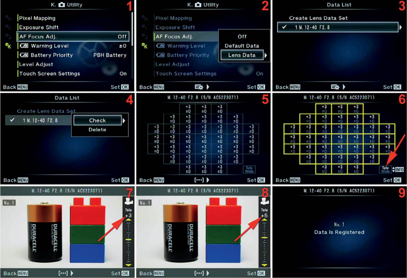
Figure 6.105C: Editing an existing focus adjustment
Use these steps to edit an existing focus adjustment:
1. Select AF Focus Adj. from the K. Utility menu and scroll to the right (figure 6.105C, image 1).
2. Highlight Lens Data on the menu and scroll to the right (figure 6.105C, image 2).
3. Notice on the screen shown in figure 6.105C, image 3, that there is an existing adjustment for a lens. It is displayed as 1 M. 12–40 F2.8 (1 indicates the lens number). Had I adjusted any other lenses, they would also appear in this list (up to 20 lens adjustments). Let’s edit the current adjustment for my M.Zuiko ED 12–40mm f/2.8 PRO lens. The lens is already selected, so we will scroll to the right.
4. The next screen lets me either Check or Delete a current lens adjustment. Choose Check and scroll to the right (figure 6.105C, image 4).
5. As you can see in the boxes of figure 6.105C, image 5, the lens is adjusted to +3 on the Tele end of the zoom range. The Tele end of the lens is indicated by the top number of each square (which represents AF points), and the Wide lens position is indicated by the bottom number in each square. After you have examined the current settings, scroll to the right.
6. Figure 6.105C, image 6, is the screen that allows you to choose which part of the focus adjustment you want to change. At the point of the red arrow you can see that I was adjusting the Tele position, and the AF rectangles indicate that the current setting is +3 forward focus. If you scroll left or right, you can deselect all 37 of the AF points and choose a single AF point to work with. If you press the Info button, you will toggle between Tele and Wide. When you have selected the AF points you want to change, press the OK button to move into the final adjustment screen.
7. At the point of the red arrow in figure 6.105C, image 7, you can see that the Tele position is set to +3 forward focus. Let’s move that to +5 to add a little more forward focus. You can see the new adjustment in image 8. I am now ready to save this new focus adjustment and retest my lens.
8. Press the OK button to save the new focus adjustment. A screen that says Data Is Registered, along with the lens number, will appear briefly (figure 6.105C, image 9). The camera will switch back to the Data List menu and display your list of lenses in case you want to edit the adjustment for another lens.
Next let’s consider how to get rid of a lens focus adjustment you no longer need.
Deleting an Existing AF Focus Adjustment for a Single Lens
If your lens has been repaired or if it miraculously starts focusing correctly, you will no longer need a focus adjustment. Let’s see how to delete it.
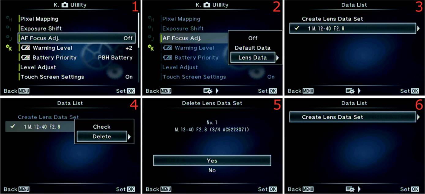
Figure 6.105D: Deleting an unneeded lens focus adjustment
Use these steps to delete an existing lens focus adjustment:
1. Select AF Focus Adj. from the K. Utility menu and scroll to the right (figure 6.105D, image 1).
2. Highlight Lens Data on the menu and scroll to the right (figure 6.105D, image 2).
3. Choose the Lens Data Set you want to Delete and scroll to the right (figure 6.105D, image 3).
4. Choose Delete from the menu and scroll to the right (figure 6.105D, image 4).
5. A Yes/No menu will appear, along with information on the Lens Data Set you are about to Delete. Select Yes and press the OK button to delete the lens adjustment (figure 6.105D, image 5). When you are done, the camera will switch back to the Data List screen, with the lens removed from the list (figure 6.105D, image 6).
Settings Recommendation: This complex function allows you to control how all or a few of your lenses focus on your camera. Even if you don’t want to use it now, why not experiment with AF Focus Adj. in case one of your lenses starts having focus problems in the future?
[Battery] Warning Level
When the battery gets low, the camera will display a battery icon with missing bars on all screens. The [Battery] Warning Level function changes the timing of when you see the low battery warning.
Let’s see how to adjust the warning level so you can see a low-battery warning sooner instead of later, if you prefer.
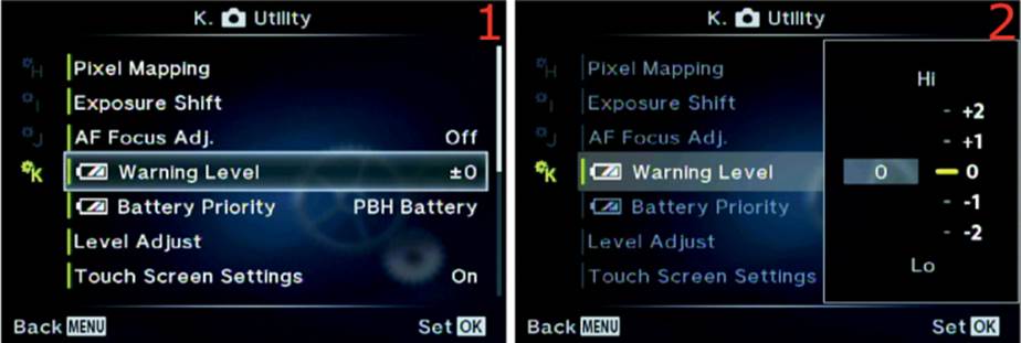
Figure 6.106: Adjusting when you will see a low-battery warning
Use these steps to choose when you will see a low-battery warning:
1. Select [Battery] Warning Level from the K. Utility menu and scroll to the right (figure 6.106, image 1).
2. You will see an adjustment range from Lo to Hi (–2 to +2), which affects how soon the camera warns you that battery is low (figure 6.106, image 2). This is not an extremely precise system. If you select a value toward the Hi side, such as +1 or +2, the camera will warn you sooner when the battery gets low. If you select a value toward the Lo side, such as –1 or –2, the camera will wait longer to warn you when the battery gets low. Select the value you want to use by moving the yellow indicator bar next to the 0 position toward the Hi or Lo position. Move the indicator bar with the up and down keys on the Arrow pad.
3. Press the OK button to Set your choice.
Settings Recommendation: I keep the [Battery] Warning Level set to Hi (+2). I want as much warning as possible so I can be prepared to change the battery. If you set it all the way down to Lo (–2), the camera may warn you when you have only enough battery life for a few more shots. In a production environment, a late low-battery warning can mean missed critical shots. Why not set your low-battery warning to Hi and see if it needs to be adjusted later?
Battery Priority
When you are using an Olympus HLD-7 Power Battery Holder (PBH) on your E-M1, the camera has two batteries at its disposal: the PBH battery and the Body Battery. This Battery Priority function gives you a choice of which battery to use first. After the camera exhausts one battery, it will automatically switch to the other one.
Most people choose to have the camera use the battery inside the PBH first so the camera can continue to operate on the Body Battery if the PBH is removed. If the Body Battery is used before the battery in the PBH and you remove the PBH, the camera will not operate due to the lack of power.
Let’s see how to select which battery the camera uses first.
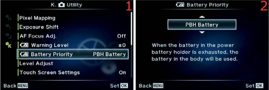
Figure 6.107: Specify which battery is used first when an HLD-7 PBH is mounted
Use these steps to choose the order of battery use when an HLD-7 PBH is mounted:
1. Select Battery Priority from the K. Utility menu and scroll to the right (figure 6.107, image 1).
2. Use the up/down menu to select PBH Battery if you want the camera to use the battery in the PBH first (factory default), or select Body Battery to use the battery in the camera first (figure 6.107, image 2).
3. Press the OK button to Set your choice of battery order.
Settings Recommendation: I always use the battery in the PBH first. I am sure there are reasons to use the battery in the camera first, but I would rather have the camera switch to the internal Body Battery when the PBH is removed instead of shutting down due to a lack of power. A single battery for the E-M1 will generally not last through a day of intense shooting, so the PBH is a welcome addition to provide shooting longevity. The weaker batteries in the camera will eventually make this choice relevant for you, so go ahead and set it according to your preferences.
Level Adjust
Normally, the camera’s leveling system tells you when your E-M1 is level for roll and pitch. However, if you need the camera to indicate that it is level at an unusual angle, you can adjust the level indicator.
Maybe you are shooting an unusual, off-level still life and you want the camera to line up with the still life’s angles instead of really being level. You can set the camera’s leveling system to match your special camera-angle requirements.
Let’s see how to make the camera report that it is level when it really isn’t—and yet it matches your special angle needs.
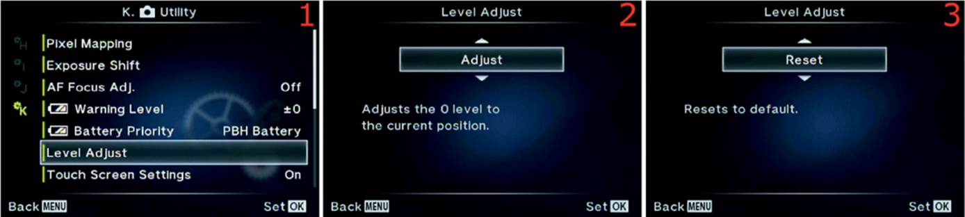
Figure 6.108: Adjusting the leveling system to give a false-level reading for special uses
Use these steps to adjust the angle the camera uses to indicate that it is level:
1. Select Level Adjust from the K. Utility menu and scroll to the right (figure 6.108, image 1).
2. Position the camera so it is at the exact angle you want it to consider level, then select Adjust from the up/down menu and press the OK button (figure 6.108, image 2). The camera will consider the new angle to be level. The level indicators will zero out and turn green when you place the camera at the new false-level angle.
3. When you are done shooting at the false-level setting, reset the camera so it will use the true level again. Select Reset from the up/down menu and press the OK button (figure 6.108, image 3).
Settings Recommendation: This is certainly an unusual setting. I have found no use for it yet since I shoot a lot of nature images. However, I can imagine that some photographers will use this feature for specialized angle shooting, especially in the studio and maybe for some types of architectural photography. If you have a need for this setting, I’m sure you will immediately recognize it.
Touch Screen Settings
The E-M1 has a nice touch screen built in to the Live View monitor on the back of the camera. You can activate various functions by simply touching an icon or button on the screen.
However, you may not like using the touch screen and would rather just use the menu system to control the camera features. Or maybe you accidentally keep touching the screen and things happen that you did not intend. In that case you can disable the touch screen. Let’s see how.
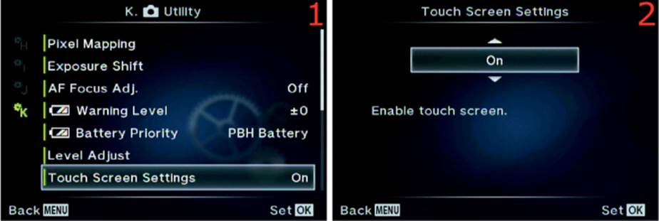
Figure 6.109: Enabling or disabling the touch screen capability
Use these steps to enable or disable the touch screen capability:
1. Select Touch Screen Settings from the K. Utility menu and scroll to the right (figure 6.109, image 1).
2. Use the up/down menu to select On to enable the Touch Screen, or select Off to disable it (figure 6.109, image 2).
3. Press the OK button to Set your choice.
Settings Recommendation: I leave the touch screen enabled on my camera. The E-M1 is the first camera I’ve ever used that has a touch screen. At first I was not all that interested in using it, then I started discovering various functions that are easier to manipulate by simply touching the screen instead of scrolling through menus. I suggest leaving the touch screen active on your camera unless you are having trouble with touching it at the wrong time.
Eye-Fi
Although the E-M1 has a built-in, full-featured Wi-Fi system that allows you to control the camera remotely and lets you transfer pictures, you can also use an Eye-Fi card (figure 6.110A) to transfer images directly to your computer over a local wireless network, to a remote computer through the Internet, or directly to a smart device (tablet or smartphone).
Figure 6.110A: Pro X2 and mobi Eye-Fi cards
Eye-Fi cards come in two basic versions: Pro X2 and mobi. Pro X2 cards can create a direct ad hoc connection to your Wi-Fi enabled computer for automatic, in-the-field image transfer from as far as 90 feet away. The mobi version is designed specifically for use with smart devices, such as tablets or smartphones.
You will find an Eye-Fi app at all the major app stores. For more information on Eye-Fi products, go to http://www.eyefi.com/.
I’ve been using Eye-Fi cards for many years, and although the E-M1 has built-in Wi-Fi, the Eye-Fi cards have some unique properties that make them worth looking into. Let’s see how to enable or disable the Eye-Fi capability.
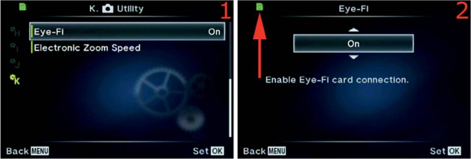
Figure 6.110B: Enabling or disabling an Eye-Fi card
Use these steps to enable or disable the camera’s Eye-Fi capability:
1. Select Eye-Fi from the K. Utility menu and scroll to the right (figure 6.110B, image 1).
2. Use the up/down menu and select On to enable Eye-Fi capability, or select Off to disable it (figure 6.110B, image 2). You will see the green Eye-Fi symbol (red arrow) at the top-left corner of the menu when an Eye-Fi card is set to On. The symbol will also appear in the top-left corner of the Live View screen, just to the left of the Wi-Fi symbol. When the card is first enabled, the Eye-Fi card symbol will blink for a few seconds while the camera sets up initial communication with the card, and it will stop blinking when the card is ready to use.
3. Press the OK button to Set your choice.
Note: The Eye-Fi selection on the Custom Menu will be grayed out and not selectable unless an Eye-Fi card is inserted into the camera.
Settings Recommendation: The Eye-Fi card can do some things the camera’s Wi-Fi system cannot do, such as send images across the Internet to a remote computer and use a local area network (Wi-Fi) to transfer images. Otherwise, the Eye-Fi functions are similar to the camera’s built-in Wi-Fi system, with less functionality for remote camera control.
Electronic Zoom Speed
Olympus makes a few power zoom lenses that allow you to zoom in and out by turning a ring or pressing camera buttons. My favorite power zoom lens is the M.Zuiko ED 14–42mm f/3.5–5.6 EZ lens. When I am out with my family, having a good time like a tourist, I often use that sharp little pancake lens to cut down on weight and bulk.
The E-M1 allows you to select three speeds for how fast the camera zooms in and out. When I am shooting still pictures, I don’t want to wait for the lens to zoom. I want it to zoom as quickly as possible so I won’t miss my shot.
However, when I am shooting video, I want the lens to zoom in and out as slowly as possible because that is less jarring and looks better in a video. The slow zoom speed allows me to smoothly pull focus for those cool focus point changes that used to be available only on video cameras that cost thousands of dollars.
Let’s see how to adjust the zoom speed of your power zoom lenses for shooting both still images and videos.
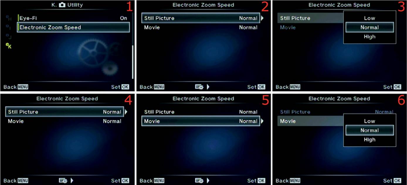
Figure 6.111: Changing the Electronic Zoom Speed for pictures and videos
Use these steps to change the power zoom speed for making pictures and videos:
1. Select Electronic Zoom Speed from the K. Utility menu and scroll to the right (figure 6.111, image 1).
2. Select Still Picture from the menu and scroll to the right (figure 6.111, image 2).
3. Select Low, Normal, or High from the menu and press the OK button to lock the Still Picture power-zooming speed (figure 6.111, image 3).
4. The camera will switch back to the menu shown in figure 6.111, image 4. Scroll down once and select Movie, as shown in figure 6.111, image 5, then scroll to the right.
5. Figure 6.111, image 6, is for adjusting the power zooming speed while you record a movie. Select Low, Normal, or High from the menu and press the OK button to lock in the Movie power-zooming speed.
6. Press the OK button to Set your choice.
Settings Recommendation: As I mentioned earlier, I like a fast power zoom when I am shooting pictures, so I set my Still Picture speed to High. I don’t like making viewers dizzy when they watch high-speed zooming in a video, so I set the Movie speed to Low. Experiment with these settings and see if this method works for you. The default Normal power-zooming speed works fine for general use, so that may be sufficient for many photographers.
Author’s Conclusions
Have you ever seen so many functions in one camera? I have never seen a camera with so many configuration possibilities. The advantage is that all these functions let you make your camera do almost any type of photography you can think of. And all this power is packed into such a diminutive camera. Do you like your E-M1 as much as I like mine?
The next chapter, Setup Menu, will cover the final functions in the camera—the initial setup functions you will probably configure only a few times while you own the camera.
All materials on the site are licensed Creative Commons Attribution-Sharealike 3.0 Unported CC BY-SA 3.0 & GNU Free Documentation License (GFDL)
If you are the copyright holder of any material contained on our site and intend to remove it, please contact our site administrator for approval.
© 2016-2026 All site design rights belong to S.Y.A.