3D Printing with SketchUp (2014)
Chapter 8. Modeling Architecture for 3D Printing
Architectural rendering is SketchUp's forte. With the many styles available in SketchUp, there is no easier program to create beautiful visualizations. With extensions and external programs that work with SketchUp files, you can create photorealistic renders and augmented reality models. As nice as these outputs are, they are still constrained to the two-dimensional confines of paper and digital screen.
Scale architectural models are incredibly useful in a way that 2D representations simply can't match. Historically, scale models were painstakingly made by hand from foam core board, wood, and the patience of an angel. More recently, laser cutters have made the tedious job of cutting easier, but designing the digital files and assembling the parts is still time consuming and rarely can the SketchUp files be used without major rework.
3D printing alleviates many of these problems. By starting with an existing architectural model, you can quickly make a 3D printable model with minimal effort. What's more, building on the techniques we discussed in Chapter 7, Importing Terrain and Printing in Color, you can even print scale architectural models in full color!
In this chapter, we will cover some advanced techniques that may be difficult if you haven't used SketchUp much. If you have trouble following along, please refer to Appendix, Resources for Your 3D Printing Success, for SketchUp training resources.
Using SketchUp for 3D printing versus rendering
Many of the requirements of a 3D printable model do not apply when modeling SketchUp models intended for visualizations. Models can be (and often are) designed as quickly as possible, with no wall thickness, with intersecting geometry, and without separate groups or components. A quick look at random models downloaded from the 3D warehouse can confirm this. While these models work just fine for their intended purpose, printing them in 3D proves tricky.
Another problem occurs when scaling the model down. Using the Tape Measure or Scale tool, you can easily shrink a model to fit in a 3D printer, but even well-built architectural models not designed with 3D printing in mind will need some rework. Small features in a rendering model such as door knobs, window trim, and window grills (muntin bars), will be much too small for the printer.
For example, a half-inch wide window grill scaled at 1:48 to fit on a small printer will only be 0.2 mm wide—much too small for most printers and certainly not strong enough to withstand handling. A good rule of thumb for most printers is not to include freestanding features smaller than 1-2 mm.
Case study – 3D printing a model designed for rendering
The small house movement (http://en.wikipedia.org/wiki/Small_house_movement) is becoming popular with people who want to live simply and have less impact on the environment. Also called micro homes, tiny cabins, and a variety of other creative names, these dwellings are often built on a trailer for portability.
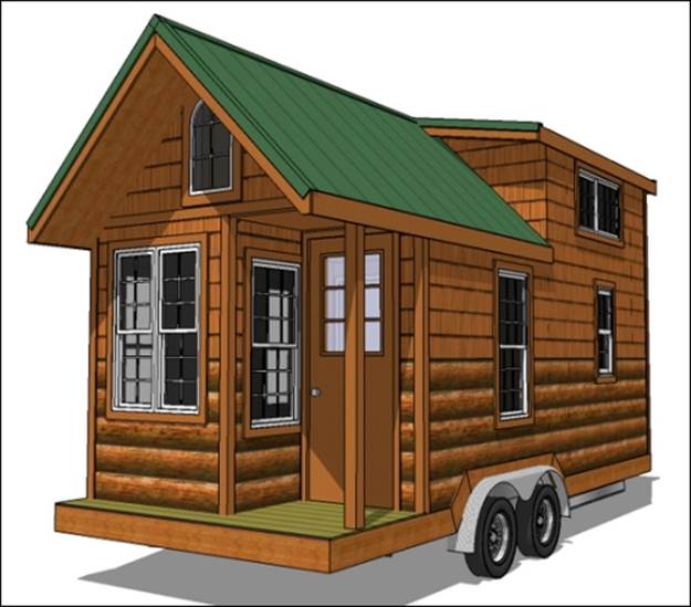
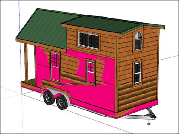
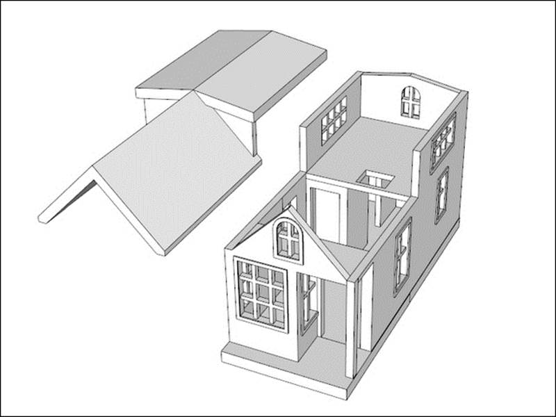
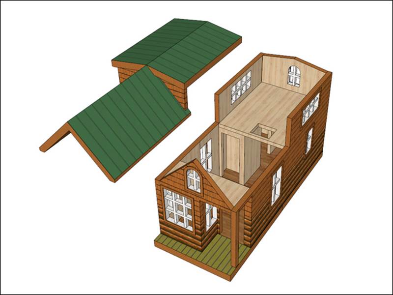
One of the clients from my architectural rendering business is a tiny cabin designer and builder. Jim Wilkins, owner of Tiny Green Cabins, will send me a hand-sketched design with measurements, which I'll model in SketchUp and render to create photorealistic images that he uses to sell the finished cabins. For folks who want to build the cabin themselves, Jim sells a set of construction plans created in Layout, which is a part of the SketchUp Pro package. In this chapter, we'll learn the steps necessary to convert the actual model I used for rendering a tiny cabin into a 3D-printable model as shown in the following image. You may follow along with an architectural model of your own, or one from the 3D Warehouse. This process will be similar for many architectural models:
Examining the original model
The following screenshot shows the original model that was made for rendering:
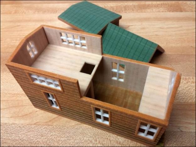
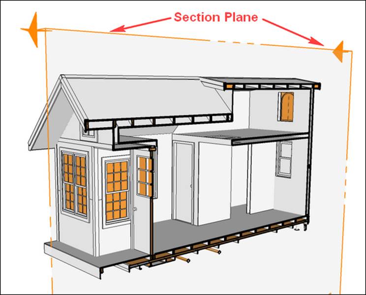
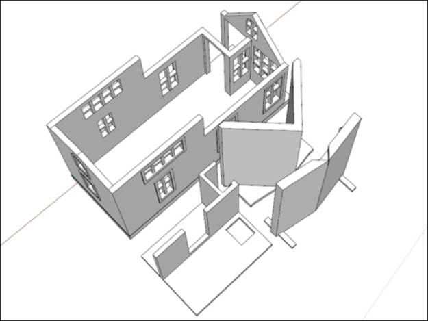
In the following screenshot, we turn the textures off (View | Face Style | Monochrome), so the back faces will show in orange. We can use the Section Plane tool to look inside the model. The Section Plane tool creates a nondestructive cut in the model, allowing you to look or work inside an enclosed space. By right-clicking on the section plane, it can be turned on or off, hidden, and reversed.
At first glance, we can see numerous issues with 3D printing the model. Because we're using the style we created in Chapter 2, Setting Up SketchUp for 3D Printing, we can see numerous back faces showing in orange that will need to be fixed. The panes of glass have no thickness, the cabin is a mass of separate nested groups and components of which many are not solid, and some features are too small to print. For this model, I will not be printing the trailer wheels and hitch, which will simplify the process and make the final print more durable.
For the first print, let's design for FFF printing. I'm going to be using my Solidoodle desktop 3D printer that has a maximum build area of 6" x 6" x 6" (150 mm x 150 mm x 150 mm). The overall length of the cabin is 24" (7.3 m), so with a little simple math (or trial and error) I know that at 1:48 scale, the model will just fit on my printer.
Note
Here's a trick to quickly resize a model to any scale; for example, 1:48—draw a line in empty space 48 mm long. Using the Tape Measure tool, first click on one end then the other end of the line, type 1 mm and hit Enter. SketchUp will ask if it's OK to resize the model, just click on Yes and voila, the model is scaled precisely. This works with any unit of measurement because you're changing the 48-unit-long line to 1 unit long and the rest of the model is scaled to match. If you have trouble with some of the imported components not scaling to match, simply enclose the entire model in a new group before scaling.
Taking into account the requirements of FFF printing, we know that the eaves will not print without support. To minimize support, we'll print the roof separately and since the roof has two separate pitches, we'll print it in two pieces. For the windows, we'll remove the glass and print just the grills for a window-like effect.
Planning the model
Trying to fix this model by making all the components solid, beefing up the thin features, and repairing the windows is doable, but would be a tedious and mentally painful process. There are extensions that attempt to automate the process, but I haven't found any that really work well. One approach that seems to work best is to use the original as a guide while constructing a new, printable model around it.
In this process, we'll create solid shapes that are of the correct thickness for printing, and assemble them like LEGO pieces into the exact shape needed. For features too small to print, we'll exaggerate their size to make them large enough for printing, or simply eliminate them. Using the Outer Shell command, at the end we'll combine all the pieces into a solid, printable model.
Thinking about the minimum features for this printer, let's plan ahead to print this model in full color. To save time then, we'll make sure this model works for both an FFF printer and a full color printer as much as possible. In the end, we'll have one model for each type of printing, each tweaked with the necessary requirements.
After checking the requirements for full color material (http://i.materialise.com/materials/multicolor/design-guide), we can see that the minimum wall thickness is 1.5-2.0 mm, and minimum detail is 0.8-1.0 mm. FFF printers can also work within these guidelines, so we'll keep them in mind while modeling.
The full color printer is powder-based, so we'll want to make the model hollow to save on material costs.
Using groups and layers to organize the model
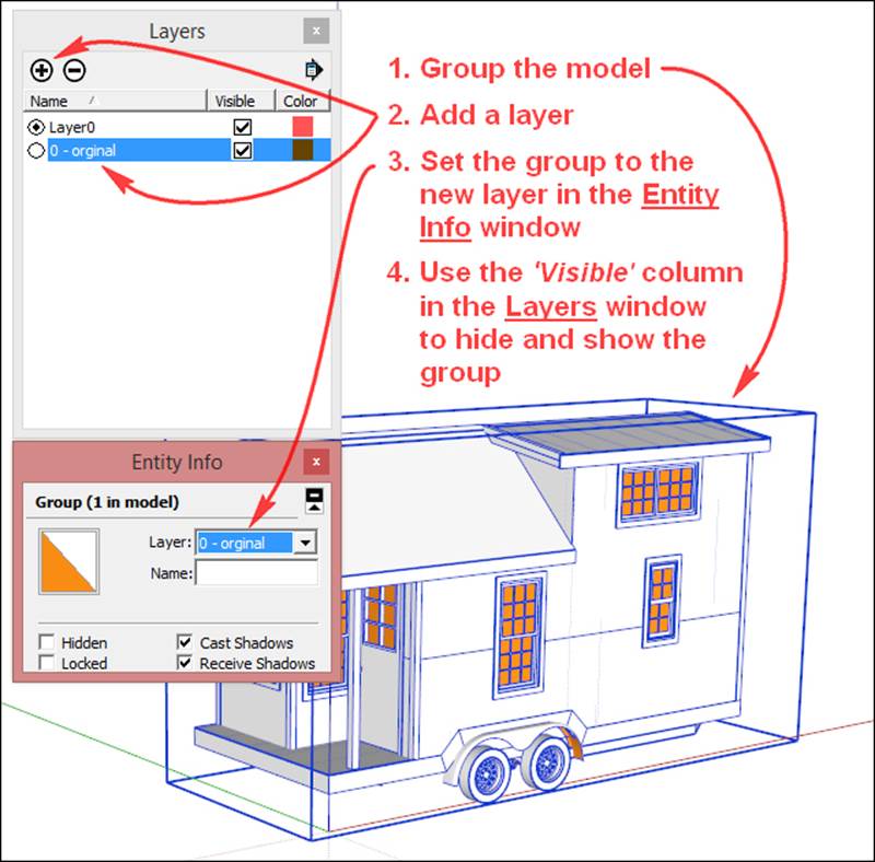
The first thing to do is group the entire cabin and place it on its own layer so that we can quickly hide and show it as needed. To do this, press Ctrl + A to select all of the geometry in the model, then navigate to Edit | Make Group. Open the Layers dialog box by navigating to Window | Layers, and clicking on the plus icon to add a layer. Name it 0 – original (if there other layers in the model, the 0 makes the new layer stay at the top of the layer list, so you can find it easily). Select the group, and in the Entity Info window, set the layer to 0 – original. Now, we can toggle visibility of the original model using the Layers window.
The following screenshot shows this process:
The Hide and Unhide commands can also be used to toggle visibility of groups in the model. Setting these commands to keyboard shortcuts can dramatically speed up your workflow.
Creating a standard wall thickness
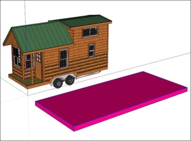
Let's begin modeling! We'll use the trailer bed as a base to provide most of the structural support, so let's make it 5 mm thick. Off to the side, draw a rectangle larger than the trailer, extrude it by 5 mm, and make it a group. Paint it with a bright color to distinguish it from the rest of the model in the next steps, as shown in the following screenshot:
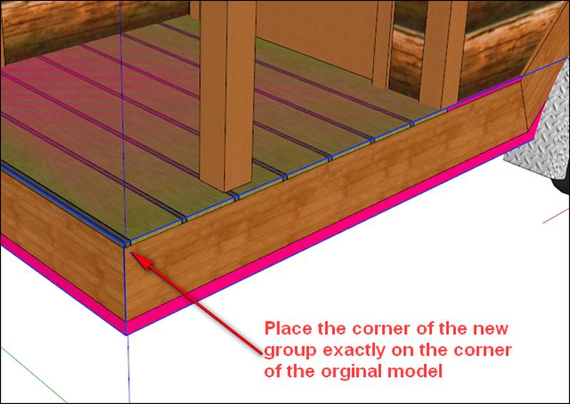
Using the Move tool, grab the top-front corner of the new trailer bed, and place it on the top-front corner of the original trailer. Zoom in closely during this operation to place the geometry precisely as shown in the following screenshot. Notice how the top is aligned, but the new geometry hangs lower to increase the thickness of the trailer bed for strength in the printed product. We can tell the top faces are aligned because of the visible "Z-fighting", which happens when two faces share the same plane and both colors fight for visibility as the model is orbited.
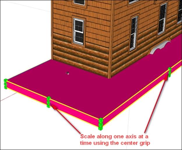
Orbit to the other side of the model where the new geometry is much too large. This is easily fixed using the Scale tool. Select the new group, click on the Scale tool and using only the center-most scale grip on one side, squash the group until it's of the correct size. Using the center-most grip will scale the group along one axis at a time, as shown in the following screenshot. The Push/Pull tool will work for this operation as well, but using the Scale tool saves the extra steps of opening and closing the group:
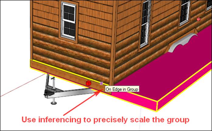
Use inferencing with the Scale tool to align the new group with the original model as shown in the following screenshot, and then repeat for the last side of the new trailer bed:
Let's make the exterior walls 3 mm thick. Create a rectangular box 3 mm wide, off to one side, as shown in the following screenshot. Make the box into a group. By copying this group and using it to create new walls in place of the existing model, we'll ensure an even 3 mm wall thickness throughout the model:
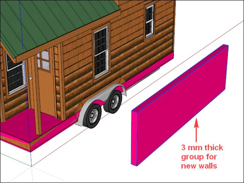
Turn off the original model layer so that it doesn't interfere, and position the new wall on the new trailer bed. Turning the original model layer on and off as needed and using the Scale tool just as we did with the trailer bed, align the new wall with the original as shown in the following screenshot. Scale only one direction (length or height) at a time and never along the thickness. This way the walls will all be of a uniform 3 mm thickness:
Copy the new wall to the opposite side of the cabin and repeat the process for each of the remaining walls. Notice that we copy the first wall to create the second, rather than drawing another from scratch. Copy and rotate the first wall by 90 degrees for the end walls.
Note
The most important thing at this point is to be precise in making sure all the walls meet at their respective corners. The walls can overlap, but if there is a gap and the walls do not touch, the Outer Shell operation and/or the final print will fail.
Editing wall panels to add details
To make the peaked gables on the end walls, scale the end wall up to the top of the peak, open that group for editing, and draw lines for the peaks, as shown in the following screenshot. Push-pull the excess material away to finish up.
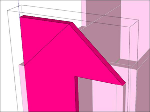
When this step is complete, the walls should look like the following screenshot. Windows and doors will be cut in the next step.
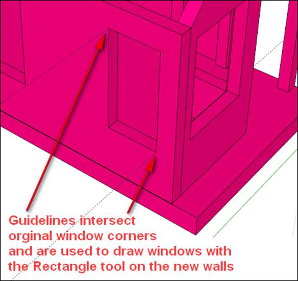
To cut the windows, turn the original model layer on and create a guideline perpendicular to the wall. Use the Move tool along with CTRL to copy and place two guidelines on each window at opposite corners. This creates two points piercing the new wall that we can use to draw a rectangle directly on the new wall and push-pull it by creating a window as shown in the following screenshot:
Adding the window grills
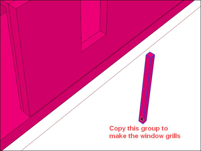
The next step is to place the window grills. This is one feature that needs to be exaggerated in order to print correctly. At a 1:48 scale, the thickness of the grills in the original model is only 0.2 mm thick—much too thin for printing on the machines we chose. Since the grills are just spanning a short distance, the minimum recommended wall thickness of 1.5 mm should work fine. Draw a square 1.5 mm x 1.5 mm, extrude it up about the height of a window, and make it a group as shown in the following screenshot:
Move it into position, inferencing the midpoint of the grill group to the midpoint on the window. Scale only along the long, vertical axis as needed to fit in the window. Make a copy and rotate it 90 degrees to create the horizontal portion, and then copy these two groups to the other windows, centering them as you go. You'll want to be careful to always make sure the window grill groups are abutting or intersecting with the wall groups, leaving no gaps that will cause problems with printing.
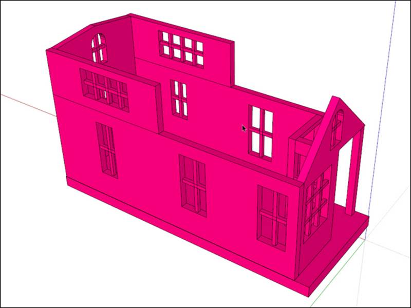
The following screenshot shows what the walls look like with all the windows and doors cut out, and the window grills in place:
Adding interior walls
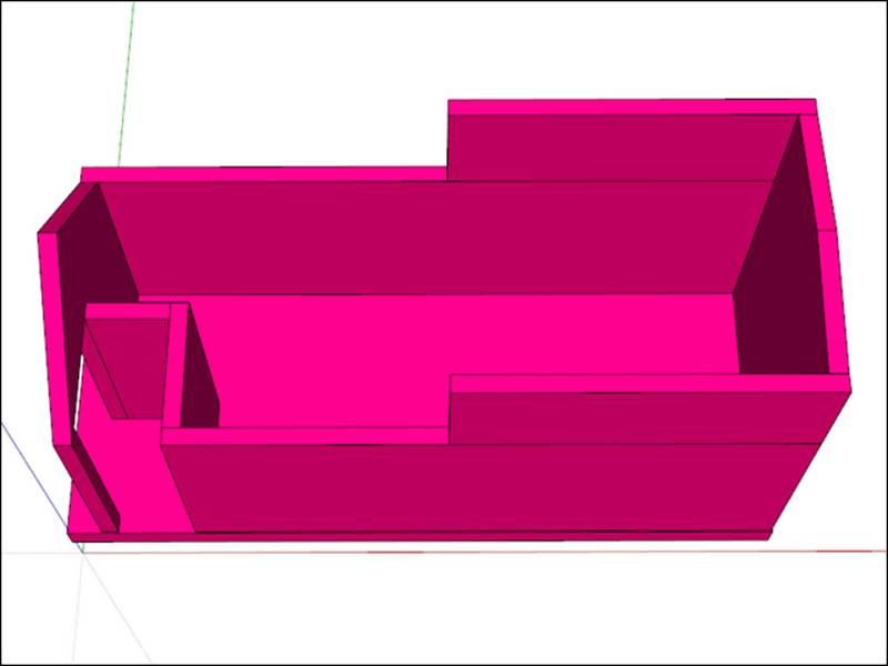
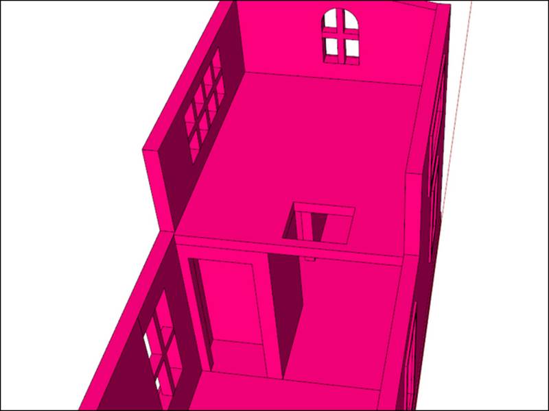
The interior walls and loft of the cabin are added using the same method we used for the exterior. Since these walls will not be handled as much, they don't need to be as strong, so we can make them thinner—2 mm will be enough. The interior is shown in the following screenshot:
Modeling the roof
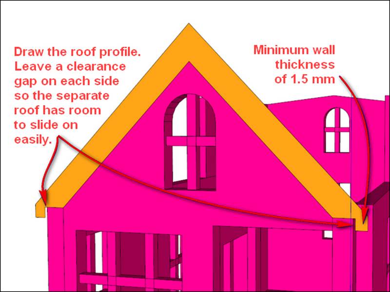
The next step is modeling the roof. First, draw the roof profile, ensuring a minimum wall thickness of 1.5 mm in all places. In the following screenshot, the overall thickness is 4 mm so that near the eaves the thickness is sufficient. In the following screenshot, notice the 0.2 mm clearance between the eaves and walls, so the separate roof isn't too tight to place on the top:
Push-pull the roof to match the length of the original model. Perform the same steps for the upper roof, and make the vertical walls to connect the space between the upper and lower roof, drawing each portion in a separate group, but combining the vertical walls and the steep roof with the Outer Shell tool.
In the following screenshot, you can see the completed roof assembly, with the rest of the model hidden:
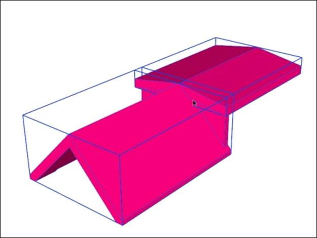
The two roof pitches are kept separate for printing on the FFF printer. Since the two roofs overlap in the center of the cabin, I used the Subtract tool in SketchUp Pro to cut away the portion that was overlapping. You can perform the same action using the Intersect with Model command in SketchUp Make. For more information on the Intersect with Model command, please refer to Chapter 6, Designing a Phone Cradle.
Orienting the parts for printing
The model is now nearly complete. In the following screenshot, notice how the roofs are positioned for easy printing with no support. The vertical walls connecting the upper and lower roofs are able to be placed flat on the print bed, while the rest of the roof geometry is self-supporting:
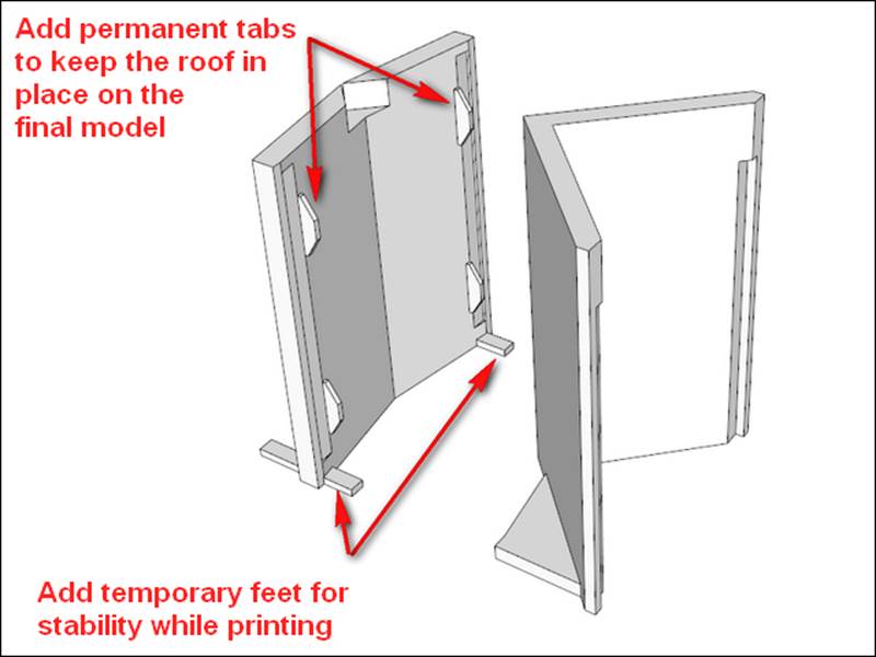
While the roofs are in the printing position, we can add more features. The shallow roof on the left has little surface area but a relatively great height. Tall, thin features like these can easily be knocked over by the print head during printing. By adding temporary feet, we can ensure that the roof will be stable for printing. These feet can be cut off with a knife after printing.
Another feature we can add now is stabilizing tabs to the shallow roof. The steep roof has ridges that can grip the top of the walls after printing, but the shallow roof does not have much to keep it from sliding off the walls. By adding tabs as shown in the previous screenshot, the roof is stabilized and the tabs are hidden on the finished model. Adding them while in the printing position allows us to be sure the tabs meet the 45-degree rule for printing overhangs without support.
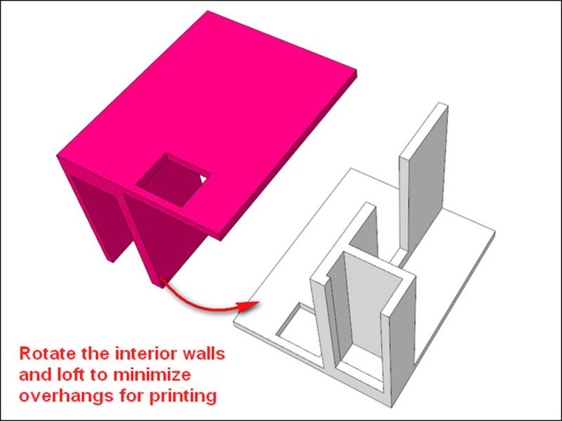
Moving on toward the interior, we can see the loft creates a large overhang that will require a lot of support if printed in place. Select the interior walls and loft, and connect them into one solid with the Outer Shell tool.
By keeping the interior walls and loft separate from the rest of the model, we can print them upside down so that no support is needed, as shown in the following screenshot:
The four sections of the model can be printed all at once on the printer with no extra support, and assembled immediately afterward with little to no hand work. The only thing remaining is to combine the walls, base, and window grill groups into one solid for printing. As usual, make a copy of everything for your historical timeline before performing the operation. This way, if you need to go back and edit a particular part of the model, the separate groups make the job much easier.
In the following screenshot, the model is completed and ready to export for printing on a desktop printer:
Printing the model and bonus commentary
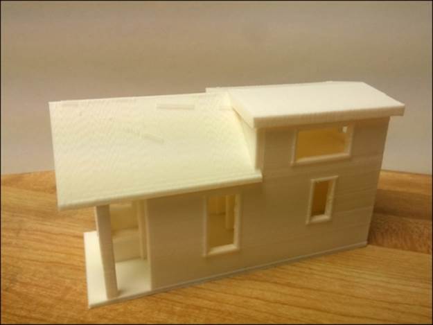
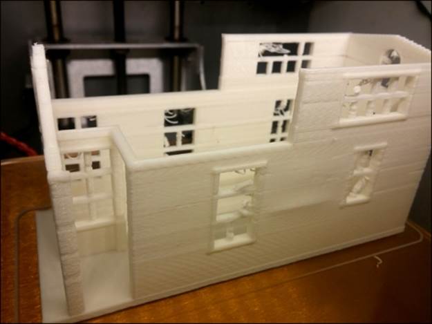
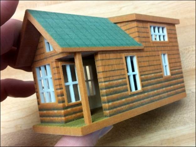
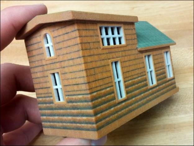
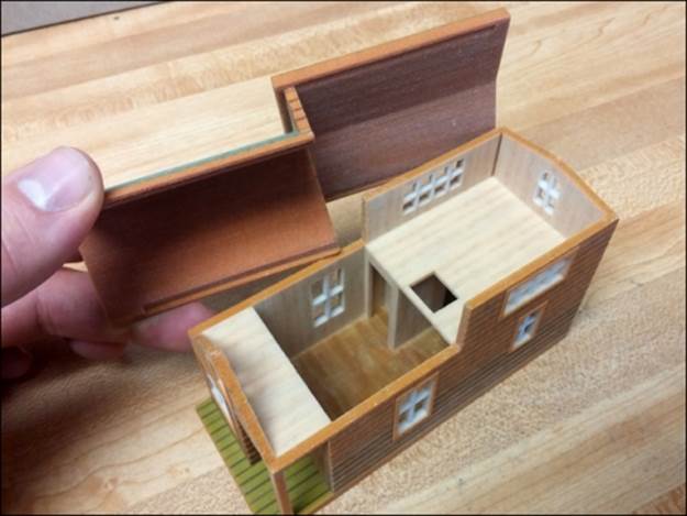
In the following three images, you can see the final printed model. All of the parts feel strong, and they fit together well. As a communication tool, this model will definitely work well:
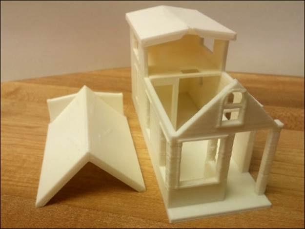
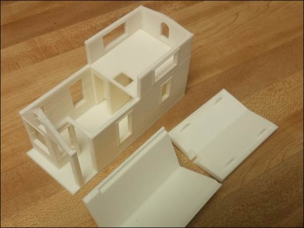
The interior walls and loft group are snapped tightly into place. As an afterthought, I could have printed the interior and the walls with the rest of the model, and printed just the loft floor separately.
You probably noticed that the windows' grills are missing—well, after printing the model twice without good results, I cut them out with a knife.
Remember how you learned tall, thin prints don't work well? A good example of that occurrence is shown in the following image, right after the printer finished making a second print of the cabin:
Notice how some of the windows look fine, but most of the vertical parts of the grills are missing. The tall thin posts easily get knocked over when the print head passes over them. On this second print, I added another horizontal bar across the tall windows to shorten the vertical bars. I also increased their thickness from 1.5 mm to 2 mm, but that still didn't work well. Any larger, and the grill would fill up too much of the window, so I felt cutting them out was the best option.
The tall, thin post on the corner of the porch proved troublesome for the same reason on the first print. Thickening it up to 4.5 mm worked well on the second print.
To save material, I reduced the base thickness to 2.5 mm in the second print from 5 mm in the original model. It still has plenty of strength, but saved significant printing time and material.
Printing this model challenged my skills on the 3D printer. Operating the printer is an art in itself, and having owned my own printer for only a few short months at the time of this writing, I have not learned all the printer settings to tweak for different situations. It is possible by changing some settings that even the windows would have printed well on this model.
Statistics are fun, right? The following are the vitals for this model:
· Printed in ABS plastic with a heated bed and enclosure
· 8 hours of printing time for a complete set of parts
· $2.25 of material, not including the re-print
This troubleshooting and reprinting experience is typical in home 3D printers, and is the reason why sending a model off to a print service can be a much better use of a designer's time. In the next section, this is exactly what we'll do!
Preparing the model for full color printing
To get the full benefit of the original textured model, we can print this model in color using the same textures applied to render the model. Refer to Chapter 7, Importing Terrain and Printing in Color, for requirements of printing in color.
Because the color printers are powder-based, the prints are self-supporting and we can combine the parts into two solids. We want the roof to be removable so that the interior layout is visible, as shown in the following screenshot. By combining the two roof parts together, and the interior and exterior walls together, we can minimize the post-printing assembly work.
Looking at the requirements for this material from the print service i.materialise http://i.materialise.com/materials/multicolor/design-guide, we can see that multiple parts are allowed in one print file, so this approach will work fine.
The i.materialise service is a good choice for beginners printing color SketchUp models because they accept the .SKP format directly. Other print services may require you to convert color models to .DAE or .WRL, and to combine all the textures in the file into a single texture map containing all of the textures in a model.
The next step will be to apply textures to the new model. Since image textures in SketchUp have a real-world scale, for texturing, it's best to scale the model back up to life size. Turning on the original model to use as a reference, apply textures and colors to the model. In this step, SketchUp's (projected textures) may not work for 3D printing.
Tip
Use the eyedropper Sample tool to quickly select a material from the original model. To use the eyedropper, select the Paint Bucket tool, then hold down the Alt key [Windows] or Command key [Mac] and select the material you want. Release the modifier key to paint the new model with that material.
To break a large face such as the floor into multiple textures, simply draw a line across the face where you want to change the texture. The line must be connected to edges on both ends to break the face. Now you can apply a different material on each side of the line.
When you complete texturing, every front face should have a texture applied, and no back face should be textured. To easily check this, change the style to show a bright color on the front face, as we discussed for back faces in Chapter 2, Setting Up SketchUp for 3D Printing. If you see an untextured face, this is the time to fix it. Use Section Plane to check the interior walls.
To check the back faces, simply reverse all of the faces; triple-click on the faces to select all faces, right-click on the model, and click on Reverse Faces. While all the faces are still selected, apply the default material to them to quickly ensure that there are no unwanted textures. Applying the default texture to the back faces will not interfere with the colored textures on the front faces. Now, you can right-click on the faces and click on Reverse Faces a second time to return the textured faces facing out.
Repeat this process for both the roof and walls' groups, making the model look like the following screenshot:
Check the model one last time to be sure both groups are solid, and fix them if necessary. Now scale the model back down to printing size. Save the model as a new file, and delete everything but the two groups that will be printed. Since i.materialise accepts SketchUp files directly, this is the model we'll upload for printing.
Orienting the parts for printing
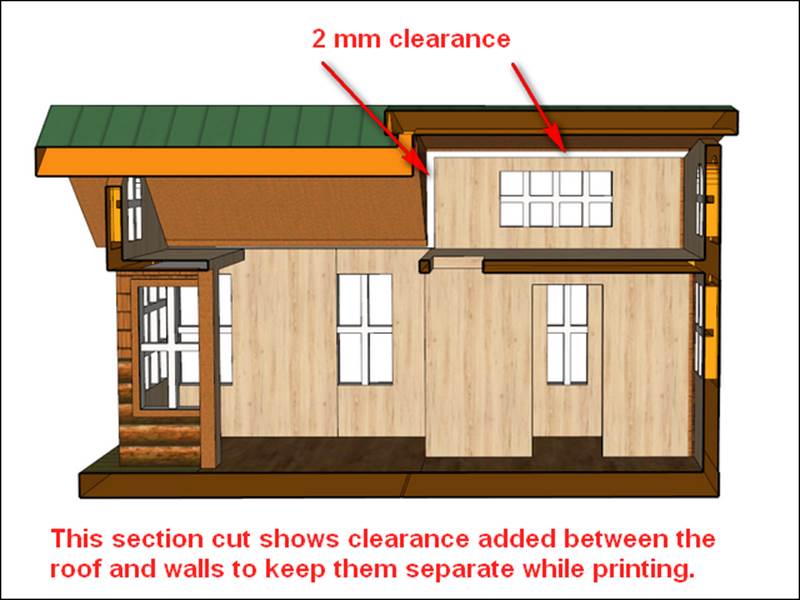
The final step is to make the model compact by positioning the two groups as near to each other as possible, minimizing their combined bounding box. (A bounding box is the smallest imaginary box the model will fit into.) This will save space in the printing tray, and the print service will give us a better price. We don't want the parts to touch or intersect though, or else the printer will fuse the two parts together.
Placing the roof in position over the walls will make the smallest bounding box for this model. The design guidelines specify a minimum of 0.4 mm clearance between two parts to keep them separate. To be safe, let's move the roof 2 mm up and 2 mm forward toward the entrance door to keep it separate from the walls, as shown in the following screenshot:
Printing from i.materialise
You can upload the model to the i.materialise website (http://i.materialise.com/), or use their extension (http://extensions.sketchup.com/en/content/3d-print-service) to upload the model directly from inside SketchUp. If you have any trouble during the upload and ordering process, you can e-mail customer service for help.
The model is ready to print via i.materialise!
Printing from Shapeways
To print this model via Shapeways, we'll have to export the model as .DAE or .WRL. Refer to Chapter 7, Importing Terrain and Printing in Color, for a step-by-step process.
More details about Shapeways requirements for color printing can be found at https://www.shapeways.com/tutorials/exporting_to_vrml_and_x3d_for_color_printing.
The full-color printed cabin
To print this model, I chose Shapeways for faster service and a slightly better price. The model arrived in about two weeks, and I could not be happier with how it turned out. The finish is somewhat rough, like a sugar cube. The colors are bright and vibrant, but I'm especially pleased with how the window grills look in the following two images:
In the following image, you can see the crisp detail of the ridge seating the base of the roof to the walls. The fit is excellent, and makes the cabin look like one piece when in place:
It's nice to place an order and get back a perfect model, printed by professionals. This approach allows you as a designer to focus on making models rather than troubleshooting failed prints. Of course, if you like the challenge of operating a 3D printer, there is nothing wrong with that!
Summary
In this chapter, you learned how to use an existing architectural SketchUp model as a template for creating a 3D-printable model. You also learned about how to split a model into parts to minimize support structures on a desktop FFF printer, and some of the adventures of trying to print the model.
We also discussed printing the models in full color from two different print services, and how your approach differs for each. Sending out a model to be printed by professionals allows you as a designer to focus on modeling and not worry about 3D printer failures.
In the Appendix, Resources for Your 3D Printing Success, you'll find a troubleshooting guide that lists solutions to problems that prevent your models from becoming solid. There is also a resource list of programs that will help you with 3D printing your SketchUp models.
All materials on the site are licensed Creative Commons Attribution-Sharealike 3.0 Unported CC BY-SA 3.0 & GNU Free Documentation License (GFDL)
If you are the copyright holder of any material contained on our site and intend to remove it, please contact our site administrator for approval.
© 2016-2026 All site design rights belong to S.Y.A.