Game Programming Algorithms and Techniques: A Platform-Agnostic Approach (2014)
Chapter 3. Linear Algebra for Games
Linear algebra is a broad category of mathematics with more than enough material for a separate book. But for 3D computer games, only a very specific subset of linear algebra is typically utilized. Rather than covering the overall theories and proofs behind linear algebra, this chapter will present the practical aspects that are most relevant to game programmers.
It cannot be overstated how important vectors and matrices are in the game programmer’s toolbox; most programmers in the industry use them every single day.
Vectors
A vector represents both a magnitude and a direction in an n-dimensional space and has one real number component per dimension. In video games, vectors are usually either 2D or 3D, depending on the number of dimensions the game supports. However, as we will discuss in Chapter 4, “3D Graphics,” there are instances where 4D vectors may be used, even though the game itself is only 3D.
A vector can be written out on paper in several different ways, but the approach used in this book is to draw an arrow above a letter to denote that it’s a vector. The components of the vector are then referenced by subscript for each dimension. The 3D vector ![]() could be represented as follows:
could be represented as follows:
![]()
So the vector ![]() 1, 2, 3
1, 2, 3![]() would have an x-component of 1, a y-component of 2, and a z-component of 3.
would have an x-component of 1, a y-component of 2, and a z-component of 3.
In code, vectors are usually represented as a class with one float per dimension:
class Vector3
float x
float y
float z
end
A vector has no concept of position. This means that two vectors are identical as long as they have the same magnitude (or length) and point in the same direction. Figure 3.1 illustrates a vector field that contains several vectors. All of the vectors in this field have the same magnitude and direction, and therefore they are equivalent.
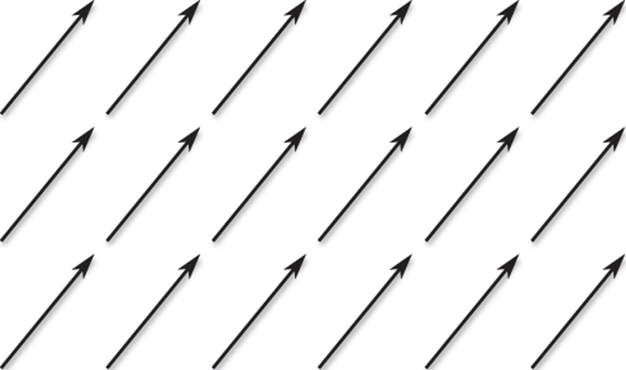
Figure 3.1 Vector field where all the vectors are equivalent.
This equality regardless of where the vectors are drawn is extremely valuable. When solving vector problems, you’ll find that it often helps if a vector is drawn at a different location. Because changing where a vector is drawn does not change the vector itself, this is a useful trick to keep in mind.
Even though where we draw a vector doesn’t change its value, it simplifies things if a vector is drawn such that the start, or tail, of the vector is at the origin (0, 0). The arrow part of the vector (the head) can then be thought as “pointing at” a specific position in space, which actually corresponds to the value of the vector. So if the 2D vector ![]() 1, 2
1, 2![]() is drawn with its tail at the origin, the head will point at the position (1, 2). This is shown in Figure 3.2.
is drawn with its tail at the origin, the head will point at the position (1, 2). This is shown in Figure 3.2.
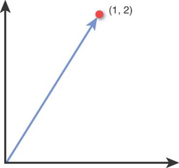
Figure 3.2 The 2D vector ![]() 1, 2
1, 2![]() drawn with its tail at the origin and its head “pointing at” (1, 2).
drawn with its tail at the origin and its head “pointing at” (1, 2).
Several basic operations can be performed on a vector. It is valuable to know the arithmetic of how to calculate these operations, but it is far more useful to understand the geometric implications of them. That’s because this geometric understanding is what will enable vectors to solve problems when you’re programming a game.
In the subsequent sections, we cover the most common vector operations. Note that although the diagrams are mostly in 2D, unless otherwise noted all operations work on both 2D and 3D vectors.
Addition
To add two vectors together, each component is individually added to the corresponding component of the other vector:
![]()
For the geometric representation of addition, draw the vectors such that the head of one vector touches the tail of the other vector. The result of the addition is the vector drawn from the tail of the first vector to the head of the second vector, as shown in Figure 3.3.
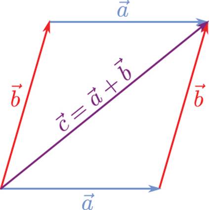
Figure 3.3 Vector addition and the parallelogram rule.
Notice how there are two permutations: one where ![]() is the first vector and one where
is the first vector and one where ![]() is the first vector. But regardless of the configuration, the result is the same. This is known as the parallelogram rule, and it holds because vector addition is commutative, just like addition between two real numbers:
is the first vector. But regardless of the configuration, the result is the same. This is known as the parallelogram rule, and it holds because vector addition is commutative, just like addition between two real numbers:
![]()
Subtraction
In vector subtraction, the components of two vectors are subtracted from each other.
![]()
To geometrically subtract two vectors, draw them such that both vectors’ tails are at the same position, as in Figure 3.4(a). Then construct a vector from the head of one vector to the head of the other. Because subtraction isn’t commutative, the order is significant. The best way to remember this is that if you want the resultant vector to go from ![]() to
to ![]() , the calculation is
, the calculation is ![]() .
.
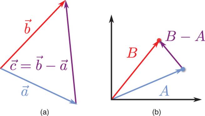
Figure 3.4 Vector subtraction (a), and representing points as vectors from the origin (b).
Subtraction is extremely important, because it enables you to construct a vector between two points. But if we always draw our vectors such that the tail is at the origin and the head aims at only one point, how can we make a vector between two points?
Well, suppose we have point A at the position (5, 2) and point B at (3, 5). What if we instead represented these points as vectors with their tails at the origin and their heads at the respective points? As we covered earlier, the values of x and y will be identical either way. But if we think of them as vectors, subtraction will allow us to construct a vector between the two, as demonstrated in Figure 3.4(b). The same principle applies as before: from A to B is B – A.
This aspect of vector subtraction is frequently used in games. For instance, imagine you are designing a UI arrow system for a game. The player is periodically given objectives he must travel to, and the game needs to display an arrow that points the player in the proper direction. In this case, the direction in which the arrow needs to face is the vector from the player to the objective, which we would calculate with:
arrowVector = objective.position – player.position
Length, Unit Vectors, and Normalization
As mentioned, vectors represent both a magnitude and a direction. The magnitude (length) of a vector is typically denoted by two lines on either side of the vector’s symbol, such as ![]() . The formula to calculate the length is as follows:
. The formula to calculate the length is as follows:
![]()
This may seem very similar to the distance formula ![]() , and that’s because we are using it! We are calculating the distance from the origin to the position at which the vector is pointing.
, and that’s because we are using it! We are calculating the distance from the origin to the position at which the vector is pointing.
Although it is not as much of an issue as in the past, taking a square root is still a relatively expensive operation. If you absolutely need the actual length of a vector for a numerical calculation, there is no way to get around the square root. However, suppose you only want to know whether object A or object B is closer to the player. In this case, you could make a vector from the player to object A as well as a vector from the player to object B. It would be possible to then take the lengths of the vectors and see which one is shorter. But because the length cannot be negative, it is also true that the comparison between the square of the length is logically equivalent:
![]()
Therefore, the expense of a square root can be avoided in instances where only a comparison is necessary. If we square both sides of the length equation, we’re left with the length squared:
![]()
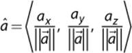
Hand in hand with length is the idea of a unit vector, or a vector whose length is one. A unit vector is typically represented with a “hat” above the vector’s symbol, as in ![]() . Converting a non-unit vector into a unit vector is known as normalization. To normalize a vector, each component must be divided by the length of the vector:
. Converting a non-unit vector into a unit vector is known as normalization. To normalize a vector, each component must be divided by the length of the vector:
Certain vector operations discussed in subsequent sections require the vectors to be normalized. However, when a vector is normalized, it will lose any magnitude information. So you have to be careful not to normalize the wrong vectors. A good rule of thumb to follow is if you only care about the direction of the vector (as in the previous UI arrow example), you should normalize the vector. If you care about both the direction and magnitude, the vector should be stored in its un-normalized form.
The Legendary “John Carmack Inverse Square Root”
In the 1990s, personal computers did not have processors that could efficiently perform mathematical operations on floating point numbers. On the other hand, operations on integers were far more efficient.
This was a problem in 3D games, because almost all calculations are done with floats instead of integers. This forced developers to come up with clever ways to perform common operations. One such problem area was the square root, and specifically the inverse square root. Why the inverse? When normalizing a vector, you can either divide each component by a square root or multiply each component by one over the square root. Multiplication was typically more efficient than division, so that’s why the inverse was chosen.
When the Quake III Arena source code was released, programmers noticed it contained a rather impressive implementation of the inverse square root. Here is the C code, presented with the actual comments (certain colorful language has been censored):
float Q_rsqrt(float number)
{
int i;
float x2, y;
const float threehalfs = 1.5F;
x2 = number * 0.5F;
y = number;
i = * ( int * ) &y; // evil floating point bit level hacking
i = 0x5f3759df - ( i >> 1 ); // what the f***?
y = * ( float * ) &i;
y = y * ( threehalfs - ( x2 * y * y ) ); // 1st iteration
return y;
}
On first glance, this code may not make much sense. But the way it works is by performing a form of Newtonian approximation. The line with the hexadecimal value is the initial guess, and then the first iteration results in an answer that is reasonably accurate.
What’s also interesting is that even though this square root is often attributed to John Carmack, the founder and technical director of id Software, he actually didn’t write it. Rys Sommefeldt tried to track down the actual author in this interesting article on Beyond3D:http://www.beyond3d.com/content/articles/8/.
Scalar Multiplication
Vectors can be multiplied by a scalar, or a single real number. To multiply a vector by a scalar, you simply multiply each component by the scalar:
![]()
If you multiply a vector by a positive scalar, it will only change the magnitude of the vector. If you multiply the vector by a negative scalar, it will also invert the direction of the vector. Figure 3.5 demonstrates a few different results of scalar multiplication.
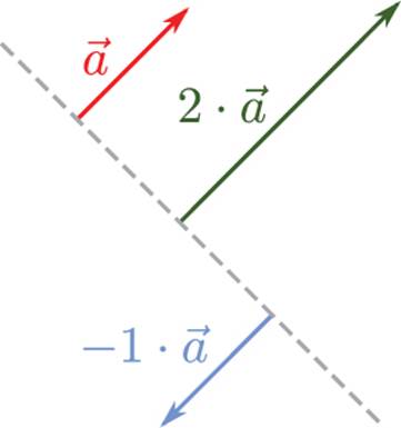
Figure 3.5 Scalar multiplication.
Dot Product
Vectors do not have a single traditional multiplication operator. Instead, they have two different products: the dot product and the cross product. The dot product results in a scalar, whereas the cross product results in a vector. One of the most common uses of the dot product in games is to find the angle between two vectors.
The dot product calculation is as follows:
![]()
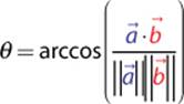
But notice how that equation does not have an angle term anywhere in it. In order to find the angle between two vectors, you must use the trigonometric formulation of the dot product:
![]()
This formulation is based on the Law of Cosines, and a full derivation of it can be found in the Lengyel book in this chapter’s references. Once we have this formulation, we can then solve for θ:
If the vectors ![]() and
and ![]() are unit vectors, the division can be omitted because the lengths of both vectors will just be one. This is demonstrated in Figure 3.6(a). The simplification of this equation is one of the reasons why you should normalize vectors in advance if you only care about their direction.
are unit vectors, the division can be omitted because the lengths of both vectors will just be one. This is demonstrated in Figure 3.6(a). The simplification of this equation is one of the reasons why you should normalize vectors in advance if you only care about their direction.
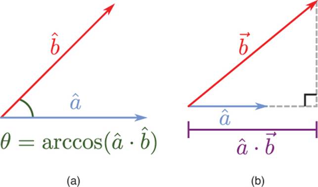
Figure 3.6 Angle between unit vectors (a), and scalar projection (b).
Because the dot product can be used to calculate an angle between two vectors, a couple of special cases are important to remember. If the dot product between two unit vectors results in 0, it means they are perpendicular to each other because cos(90°) = 0. If the dot product results in 1, it means the vectors are parallel and facing in the same direction, and –1 means they are parallel and face in the opposite direction.
Another important aspect of the dot product is what’s known as the scalar projection, which is illustrated in Figure 3.6(b). In this application, you have both a unit vector and a non-unit vector. The unit vector is extended such that a right triangle is formed with the other vector. In this case, the dot product will return the length of the extended unit vector.
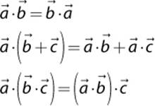
As with multiplication between two real numbers, the dot product is commutative, distributive over addition, and associative:
Another useful tip is to also think of the length squared calculation as being equivalent to the dot product of the vector with itself—or in other words:
![]()
Sample Problem: Vector Reflection
Now that we’ve covered several different types of vector operations, let’s apply them to an actual video game problem. Suppose you have a ball that is travelling toward a wall. When the ball hits the wall, you want it to reflect off of the wall. Now, if the wall is parallel to one of the coordinate axes, this is simple to solve. For example, if the ball bounces off a wall that parallels the x-axis, you can simply negate the velocity in the y-direction.
But negating the x or y velocity does not work if the wall is not parallel to an axis. The only solution to this generalized reflection problem is to use vector math. If we can compute the reflection with vectors, it will work for any arbitrary orientation of the wall.
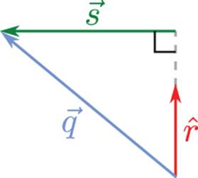
Vector problems can be difficult to solve without visualizing them on a sheet of paper. Figure 3.7(a) shows the initial state of this problem. There are two known values: the vector ![]() , which is the velocity of the ball prior to reflection, and the normal
, which is the velocity of the ball prior to reflection, and the normal ![]() , which is a unit vector that is perpendicular to the surface of reflection. We need to solve for the vector
, which is a unit vector that is perpendicular to the surface of reflection. We need to solve for the vector ![]() , which represents the velocity after reflection.
, which represents the velocity after reflection.
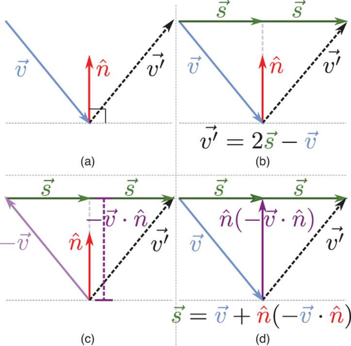
Figure 3.7 Steps to solve vector reflection.
If we had a vector from the tail of ![]() to the head of
to the head of ![]() , it would be possible to calculate
, it would be possible to calculate ![]() by using vector subtraction. Figure 3.7(b) draws this hypothetical vector as 2
by using vector subtraction. Figure 3.7(b) draws this hypothetical vector as 2![]() . This means that if we can figure out the value of
. This means that if we can figure out the value of ![]() , it will be possible to solve the entire problem.
, it will be possible to solve the entire problem.
If there were some way to extend ![]() so that its head were drawn at the same location as the head of
so that its head were drawn at the same location as the head of ![]() , it would be possible to calculate
, it would be possible to calculate ![]() by vector addition. Figure 3.7(c) shows that if the direction of
by vector addition. Figure 3.7(c) shows that if the direction of ![]() is reversed, we can use scalar projection to determine the distance of the extended
is reversed, we can use scalar projection to determine the distance of the extended ![]() . Because
. Because ![]() is a unit vector, if we scalar multiply it by this computed distance, we will get our extended
is a unit vector, if we scalar multiply it by this computed distance, we will get our extended ![]() . Figure 3.7(d) shows this extended vector, which can then be used to calculate the value of
. Figure 3.7(d) shows this extended vector, which can then be used to calculate the value of ![]() .
.
Now that we have the value of ![]() , we can substitute back into the equation from Figure 3.6(b) and perform some simple algebra to get the final solution for
, we can substitute back into the equation from Figure 3.6(b) and perform some simple algebra to get the final solution for ![]() :
:
When you’re solving vector problems, it is useful to make sure you ultimately are performing valid vector operations. For example, if a solution to a vector problem suggested that a vector should be added to a scalar, it would have to mean the solution is wrong. This is much like checking to make sure the units line up in physics.
So let’s look at our solution to the vector reflection problem. In order to do vector subtraction with ![]() , the result of
, the result of ![]() must be a vector. If we look at this expression more closely, we first scalar multiply
must be a vector. If we look at this expression more closely, we first scalar multiply ![]() by 2, which results in a vector. We then scalar multiply this vector by the scalar result of a dot product. So, ultimately, we are subtracting two vectors, which certainly is valid.
by 2, which results in a vector. We then scalar multiply this vector by the scalar result of a dot product. So, ultimately, we are subtracting two vectors, which certainly is valid.
This vector reflection problem is a great example of how to use the vector operations we’ve covered thus far. And it also turns out that it’s an extraordinarily common interview question posed to potential game programmers.
Cross Product
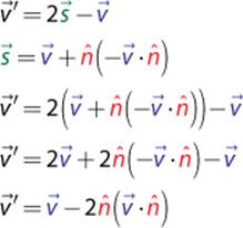
The cross product between two vectors results in a third vector. Given two vectors, there is only a single plane that contains both vectors. The cross product finds a vector that is perpendicular to this plane, as in Figure 3.8(a), which is known as a normal to the plane.
Because it returns a normal to a plane, the cross product only works with 3D vectors. This means that in order to take a cross product between two 2D vectors, they first must be converted to 3D vectors via the addition of a z-component with a value of 0.
The cross product is written as follows:
![]()
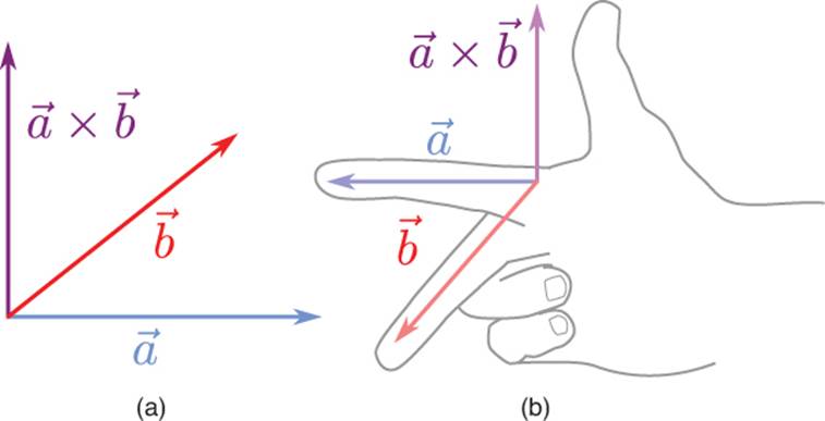
Figure 3.8 Cross product (a), and right-hand rule (b).
An important thing to note is that there is technically a second vector that is perpendicular to the plane: the vector that points in the opposite direction of ![]() . So how do you know which direction the cross product result should face? The answer is tied into what is known as the handedness of the coordinate system. In a right-handed system, you take your right hand and create a 90° angle between your thumb and index finger. You likewise make a 90° angle between your index finger and your middle finger. You then line up your index finger with
. So how do you know which direction the cross product result should face? The answer is tied into what is known as the handedness of the coordinate system. In a right-handed system, you take your right hand and create a 90° angle between your thumb and index finger. You likewise make a 90° angle between your index finger and your middle finger. You then line up your index finger with ![]() and your middle finger with
and your middle finger with ![]() . The direction your thumb points in is the direction the cross product will face. Figure 3.8(b) shows an application of the right-hand rule.
. The direction your thumb points in is the direction the cross product will face. Figure 3.8(b) shows an application of the right-hand rule.
You may have noticed that if you switch it so your index finger lines up with ![]() and your middle finger with
and your middle finger with ![]() , your thumb points in the opposite direction. This is because the cross product is not commutative, but in fact anti-commutative:
, your thumb points in the opposite direction. This is because the cross product is not commutative, but in fact anti-commutative:
![]()
It is important to remember that not all games use a right-handed coordinate system. We will describe coordinate systems in greater detail later, but for now let’s assume a right-handed coordinate system.
Now that the cross product has been covered conceptually, let’s look at how it is calculated:
![]()
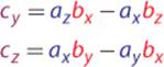
Remembering how to calculate the cross product just from the preceding formula is difficult. Luckily, there is a mnemonic to help us remember: “xyzzy.” The way the mnemonic works is it tells us the order of the subscripts for the first component of the cross product:
![]()
If you can remember the base equation is c = a·b–a·b, “xyzzy” tells you which subscript to use for each term. Once you have the first line, you can figure out cy and cz by rotating the subscripts in the following manner: x → y → z → x. This will then give you the next two lines of the cross product:
As with the dot product, there is a special case to watch out for. If the cross product returns a vector where all three components are 0, this means that the two input vectors are collinear, or they lie on the same line. Two collinear vectors cannot form a plane, and because of that there is no normal for the cross product to return.
Because a triangle is guaranteed to always be on a single plane, we can use the cross product to determine the vector that’s perpendicular to the triangle. This perpendicular vector is known as the normal of the triangle. Figure 3.9 shows triangle ABC. In order to calculate the normal, we first must construct vectors from A to B and from A to C. Then if we take the cross product between these two vectors, in a right-handed coordinate system we would get a vector going into the page, which corresponds to the direction of the normal.
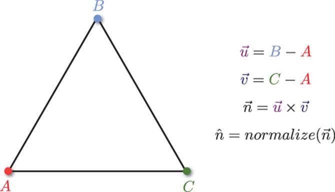
Figure 3.9 The normal going into the page for triangle ABC (in a right-handed coordinate system).
Because we only care about the direction of the normal, and not the magnitude, we should make sure to always normalize this vector. This concept of a normal does not apply only to triangles; any polygon has a single normal as long as it lies on a single plane.
Note that we could also take the cross product in the opposite order, in which case we would still get a vector perpendicular to the triangle’s plane, although it will be facing in the opposite direction. Chapter 4 discusses the concept of winding order, which determines the order in which we should perform the cross product.
Sample Problem: Rotating a 2D Character
Let’s take a look at another sample problem. Suppose we have a top-down action game where a player character moves through the world. We are scripting an in-game cutscene where an explosion occurs at a specific location, and we want the player to turn and face this explosion. However, the cutscene can trigger in a variety of scenarios, so the initial direction the player is facing is variable. We also do not want the player to suddenly snap to face the explosion; rather, it should be a smooth transition over a brief period of time.
We need to determine two different things in order to perform a smooth transition. First, we need the angle between the current facing vector and the new facing vector of the player. Once we have that, we then need to figure out whether the character should rotate clockwise or counterclockwise. Figure 3.10 presents a visualization of this problem.
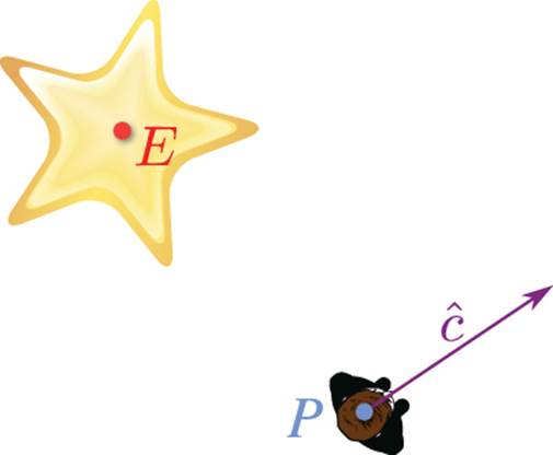
Figure 3.10 The player needs to rotate to face the explosion.
The vector cy represents the current direction the player is facing. P is the position of the player in the world, and E is the position of the explosion. The first step to solve this problem is to construct a vector that points in the direction of the explosion. We want the vector from P to E, so the calculation should be E – P. Because we only care about the direction in this problem, and not the distance, we should go ahead and normalize this vector. Therefore, we can define ![]() as the unit vector that points in the direction of the explosion.
as the unit vector that points in the direction of the explosion.
Now that we have the current and new directions, how do we find the angle between the two vectors? The answer is the dot product. Because both ![]() and
and ![]() are unit vectors, the angle θ can be calculated with
are unit vectors, the angle θ can be calculated with ![]() .
.
But the dot product can’t tell us whether it’s θ in the clockwise or counterclockwise direction. To determine this, we must use the cross product. Because the cross product only works on 3D vectors, ![]() and
and ![]() must be converted to 3D vectors by adding a z-component of 0:
must be converted to 3D vectors by adding a z-component of 0:
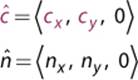
Once the vectors are 3D, we can calculate ![]() . If the z-component of the resultant vector is positive, it means that the rotation is counterclockwise. On the other hand, a negative z-component means the rotation is clockwise. The way to visualize this is by using the right-hand rule. If you go back to Figure 3.10 and position your index finger along ĉ and your middle finger along ĉ, your thumb should point out of the page. In a right-handed coordinate system, this is a positive z value, which is a counterclockwise rotation.
. If the z-component of the resultant vector is positive, it means that the rotation is counterclockwise. On the other hand, a negative z-component means the rotation is clockwise. The way to visualize this is by using the right-hand rule. If you go back to Figure 3.10 and position your index finger along ĉ and your middle finger along ĉ, your thumb should point out of the page. In a right-handed coordinate system, this is a positive z value, which is a counterclockwise rotation.
Linear Interpolation
Linear interpolation, or lerp, calculates a value somewhere linearly between two other values. For example, if a = 0 and b = 10, a linear interpolation of 20% from a to b is 2. Lerp is not limited to only real numbers; it can be applied to values in any number of dimensions. It is possible with points, vectors, matrices, quaternions, and many other types of values. Regardless of the number of dimensions, lerp can be applied with the same generic formula:
Lerp(a,b,f) = (1–f)·a + f·b
Here, a and b are the values being interpolated between and f is a fractional value in the range of [0,1] from a to b.
In games, a common application of lerp is to find a point between two other points. Suppose there is a character at point a and it needs to be smoothly moved to b over time. Lerp will allow you to slowly increase f until it hits 1, at which point the character will be at point b (see Figure 3.11).
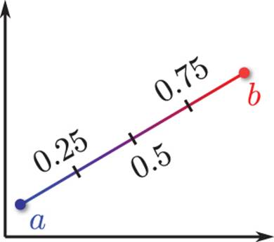
Figure 3.11 Lerp from a to b with different f values.
Coordinate Systems
Not all games use the same 3D coordinate system. Some coordinate systems may have the y-axis as up, whereas others may use the z-axis. Some might be right-handed coordinate systems while others might be left-handed. Selection of a coordinate system is arbitrary and often comes down to personal preference. Most games seem to prefer systems where the y-axis is up and the z-axis goes into or out of the screen, but there is no mathematical basis for this preference.
Because there is no one set way to express a 3D system, whenever you’re working with a new framework it is important to check which coordinate system it uses. It ultimately doesn’t matter which coordinate system a game uses, as long as it’s consistent across the codebase (see the sidebar “A Coordinate System Mix-Up” for a humorous instance where this wasn’t the case).
Sometimes it may be a requirement to convert from one coordinate system to another. A common occurrence of this is when a 3D modeling program uses a different coordinate system than the game itself. Converting from one coordinate system to another may require negating a component or swapping components. It just depends on what the two coordinate systems are. For example, Figure 3.12 shows two y-up coordinate systems: a right-handed one and a left-handed one. In this particular case, the conversion is relatively simple: To switch from one to the other, just negate the z-component.
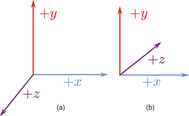
Figure 3.12 Sample right-handed (a) and left-handed (b) coordinate systems.
A Coordinate System Mix-Up
On Lord of the Rings: Conquest, one of my primary responsibilities was to provide programming support for the sound team. Early on in the project, the lead sound designer came to me with a peculiar issue. He noticed that when an explosion occurred on the left side of the screen, it came out of the right speaker, and vice versa. He had checked his speaker wires several times, and was sure that he had the correct speakers connected to the correct inputs on the receiver.
A bit of digging around uncovered the issue: Most of our game’s code used a left-handed coordinate system, whereas our third-party sound library used a right-handed coordinate system. This resulted in the wrong coordinates being passed into the sound system. The solution was to convert the coordinates to right-handed when passing them into the sound library. Once this was changed, the sounds started coming out of the correct speakers for the first time on the project.
By default, DirectX uses a left-handed y-up coordinate system, and OpenGL uses a right-handed y-up coordinate system. However, this does not mean that all games using these libraries must use the default coordinate systems because it’s relatively straightforward to configure both to use a different coordinate system.
Sometimes the x-, y-, and z-axes are instead referred to as the ![]() ,
, ![]() , and
, and ![]() basis vectors. The basis vectors are what formally define the coordinate system. As we will discuss in Chapter 4, the generic way to change from any arbitrary coordinate system to another is by using a change of basis matrix. But before we can construct one of these, we first must cover matrices.
basis vectors. The basis vectors are what formally define the coordinate system. As we will discuss in Chapter 4, the generic way to change from any arbitrary coordinate system to another is by using a change of basis matrix. But before we can construct one of these, we first must cover matrices.
Matrices
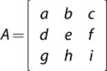
A matrix is a grid of real numbers, with m rows and n columns, and is typically expressed by a capital letter. For games, 3×3 and 4×4 matrices are the most common. A 3×3 matrix could be written as such, where the letters a through i simply represent numbers within the matrix:
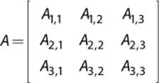
Another method for matrix declaration is to use subscript coordinates to refer to the specific elements. The preceding matrix could be rewritten as follows:
In 3D games, matrices are used to transform, or change, vectors and positions. We will cover these types of transformations in Chapter 4. For now, let’s cover the basic matrix operations.
Addition/Subtraction
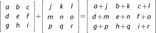
Two matrices can be added or subtracted if they both have the same dimensions. To add them, simply add the corresponding components to each other.
Subtraction is the same, except the components are subtracted. Both of these operations rarely see use in games.
Scalar Multiplication
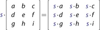
As can be done with vectors, it is possible to multiply a matrix by a scalar.
Multiplication
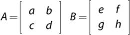
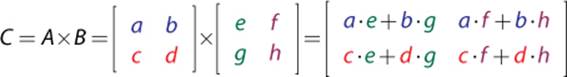
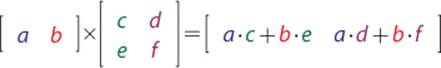
Matrix multiplication is an operation that sees widespread use in games. The easiest way to visualize matrix multiplication between two matrices with the same dimensions is to think in terms of vectors and dot products. Suppose you have matrices A and B, as shown here:
To calculate C = A×B, take the first row of A and dot product it with the first column of B. The result of this dot product is the top-left value in C. Then dot product the first row of A with the second column of B, which gives the top-right value in C. Repeat this process for the second row of Ato complete the multiplication.
Matrix multiplication does not require matrices to have identical dimensions, but it does require that the number of columns in A be equal to the number of rows in B. For instance, the following multiplication is also valid:
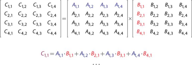
Multiplying two 4×4 matrices follows the same principle as smaller ones; there are just more elements to calculate:
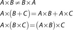
It is important to note that matrix multiplication is not commutative, though it is associative and distributive over addition:
Another important property of matrix multiplication is the identity matrix. If you multiply a scalar value by 1, it does not change. Similarly, multiplying a matrix by the identity matrix I does not change the matrix’s value.
A = A×I
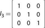
The identity matrix has a number of rows and columns equal to the number of columns in A, and values within the identity matrix are all zeroes except for a diagonal of ones. Therefore, a 3×3 identity matrix looks like this:
Inverse
If a matrix is multiplied by its inverse, denoted by –1, the result is the identity matrix:
I = A×A–1
Calculation of the inverse of an arbitrary matrix is a somewhat advanced topic, so it is not covered in this book. However, it is important to know that not all matrices have an inverse, but in games a matrix with no inverse typically means a calculation has gone awry. Thankfully, the transformation matrices covered in Chapter 4 have inverses that are relatively straightforward to compute.
Transpose
A transpose of a matrix, denoted by T, takes each row of a matrix and converts it to a corresponding column. So the first row becomes the first column, the second row becomes the second column, and so on. Here is the transpose of a 3×3 matrix:
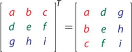
For certain types of matrices known as orthonormal matrices, the inverse of the matrix is its transpose. Rotation matrices are one example of this type of matrix.
Transforming 3D Vectors by Matrices
In order to apply a matrix transformation to a vector, the two must be multiplied together. But before multiplication can occur, the vector must first be represented as a matrix. It turns out there are two potential ways to represent a vector as a matrix: It could be a matrix with a single row or a matrix with a single column. These representations are referred to as row-major and column-major, respectively.
Given the vector ![]() =
= ![]() 1, 2, 3,
1, 2, 3,![]() , the row-major matrix representation would be this:
, the row-major matrix representation would be this:
![]()
Whereas the column-major representation would be this:

If you have a matrix that is intended to be multiplied with row-major vectors, but instead want to multiply it by a column-major one, the matrix must be transposed. Take a look at how a 3D vector is multiplied by a 3×3 matrix first in row-major form and then in column-major form:
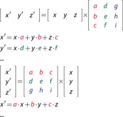
Notice how the value of x′ is identical in both representations. But this is only the case because the 3×3 matrix was transposed. As with handedness, it doesn’t matter whether row-major or column-major is selected, as long as it’s consistent. Because most 3D game libraries utilize a row-major representation (with OpenGL being a major exception), that’s what is used in this book.
Summary
Although the topic of linear algebra may not be the most exciting to prospective game programmers, the value of it is indisputable. A strong grasp of linear algebra is often the difference between someone who wants to program 3D video games and someone who does program 3D video games. We will be using both vectors and matrices at many other points throughout this book, so it is extraordinarily important that these concepts are fully digested before moving on.
Review Questions
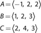
1. Given the vectors ![]() and
and ![]() and the scalar value s = 2, calculate the following:
and the scalar value s = 2, calculate the following:
a. ![]()
b. ![]()
c. ![]()
2. What is a good rule of thumb for whether or not a particular vector should be normalized?
3. Given the position of the player, P, how do you efficiently determine whether it is closer to point A or point B?
4. Given the vectors ![]() and
and ![]() in the following diagram, solve for
in the following diagram, solve for ![]() using vector operations.
using vector operations.
5. Given the following triangle, calculate θ using vectors:
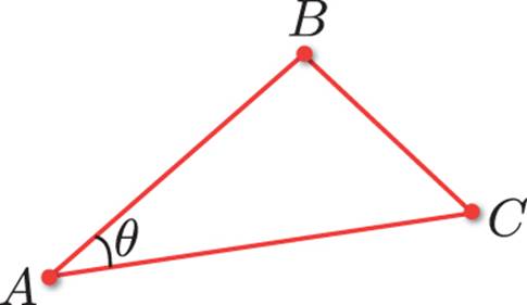
6. Using the previous triangle, calculate the surface normal coming out of the page in a right-handed coordinate system.
7. If the order of the cross product is reversed, what happens to the result?
8. You are tasked with implementing simple stereo sound in a top-down action game. When a sound plays in the world, you must determine whether to play the sound out of the left or right speaker based on the orientation of the sound relative to the player. How could this be solved using vector math?
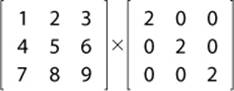
9. Calculate the result of the following matrix multiplication:
10. When is the transpose of a matrix equal to its inverse?
Additional References
Lengyel, Eric. Mathematics for 3D Game Programming and Computer Graphics (Third Edition). Boston: Course Technology, 2012. This book contains detailed explanations of the concepts covered in this chapter, complete with derivations and proofs. It also covers more complex math, which is beyond the scope of this book, but still gets some use by game programmers (especially those who focus on graphics).
All materials on the site are licensed Creative Commons Attribution-Sharealike 3.0 Unported CC BY-SA 3.0 & GNU Free Documentation License (GFDL)
If you are the copyright holder of any material contained on our site and intend to remove it, please contact our site administrator for approval.
© 2016-2026 All site design rights belong to S.Y.A.