Make: Basic Arduino Projects - 26 Experiments with Microcontrollers and Electronics (2014)
Chapter 3. Tilt Sensing Servo Motor Controller
Sensors allow people to operate consumer and industrial products using physical stimuli such as touch, sound, and motion. In Chapter 2, you controlled two LEDs with the wave of your hand; the light-activated switch used a photocell to detect the presence of your hand over the sensor.
In this chapter, we’ll build a gadget to easily detect object orientation using a tilt control switch to control a servo motor. This is an awesome device to build and show your Maker smarts to family and friends. By rotating the tilt control switch in an upright position, you’ll be able to operate a servo motor. Figure 3-1 shows the Tilt Sensing Servo Motor Controller.
Parts List
§ Arduino microcontroller
§ SW1: tilt control switch
§ JI: servo motor
§ R1: 1K ohm resistor (brown, black, red stripes)
§ Pair of alligator test leads or equivalent
§ Full-size clear breadboard
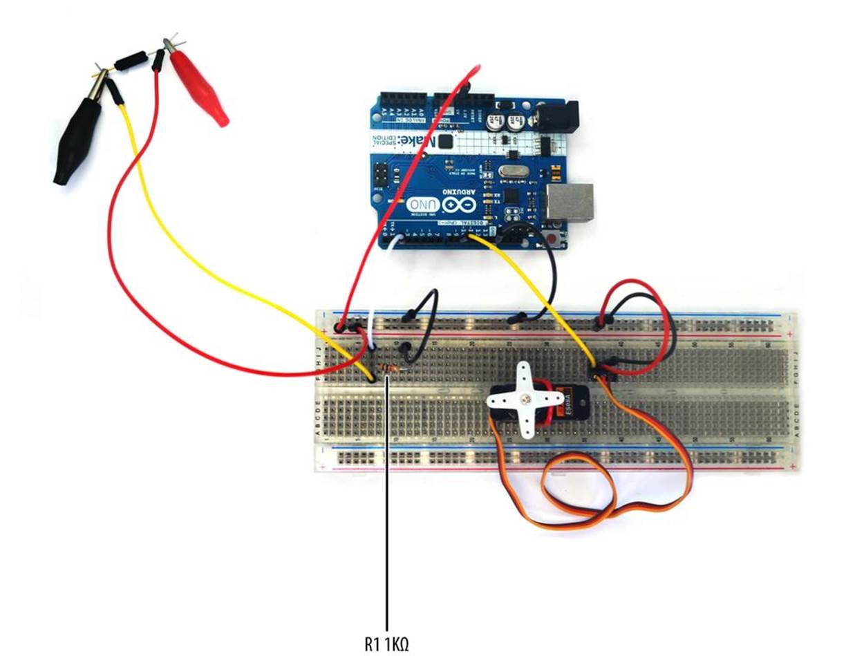
Figure 3-1. Tilt Sensing Servo Motor Controller built on a full-size clear breadboard
Let’s Build a Tilt Sensing Servo Motor Controller
You can control a servo motor’s rotation direction through orientation detection using a tilt control switch. In this project, you will build a Tilt Sensing Servo Motor Controller. Refer to the Parts List for all the electronic components required for this project. Here are the steps used to build the electronic device:
1. From the Ultimate Microcontroller Pack, place the required parts on your workbench or lab tabletop.
2. Assemble the servo motor with the appropriate mechanical assembly attachment, as shown in Figure 3-2 (left).
3. Strip insulation from three ¼-inch solid wires and insert them into the servo motor’s mini connector, as shown in Figure 3-2 (right).
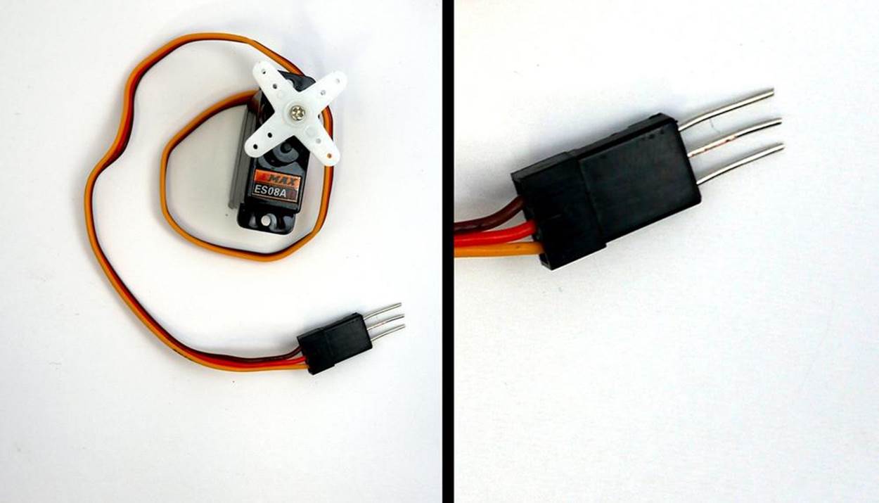
Figure 3-2. Servo motor with mechanical assembly attachment and modified servo motor wire connector (left); close-up of modified servo motor wire connector (right)
4. Place and secure the servo motor on the full-size clear breadboard with hookup wire, as shown in Figure 3-3.
5. Insert the modified servo motor wire connector into the full-size clear breadboard, as shown in Figure 3-4.
6. Wire the electronic parts using the Fritzing diagram of Figure 3-5, or the actual project shown in Figure 3-1.
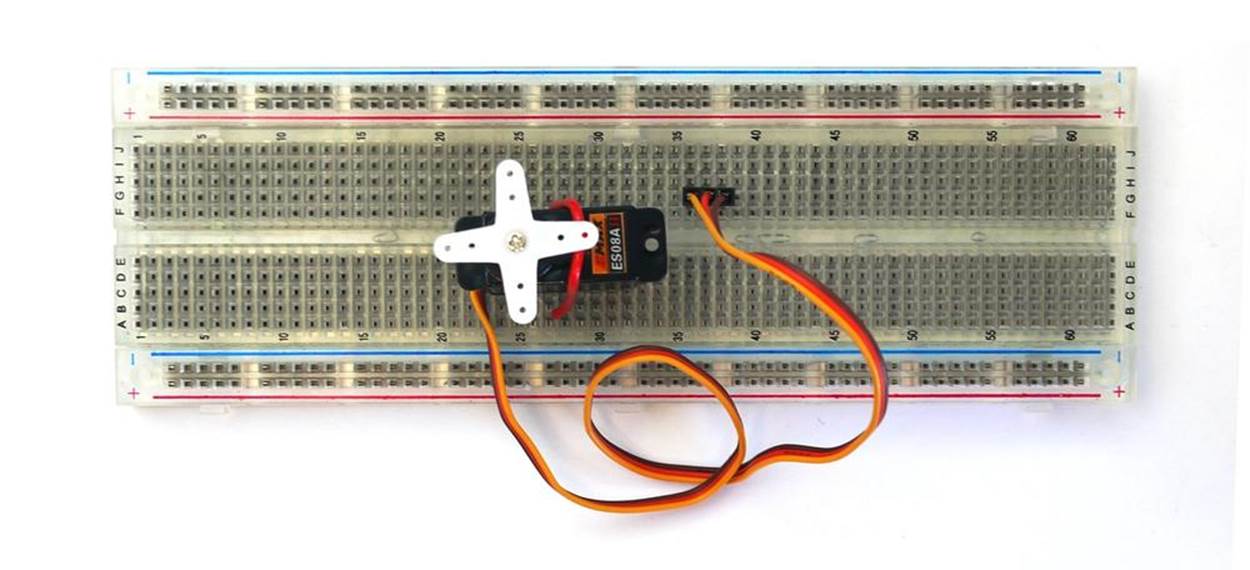
Figure 3-3. Placing and securing the servo motor on the full-size clear breadboard
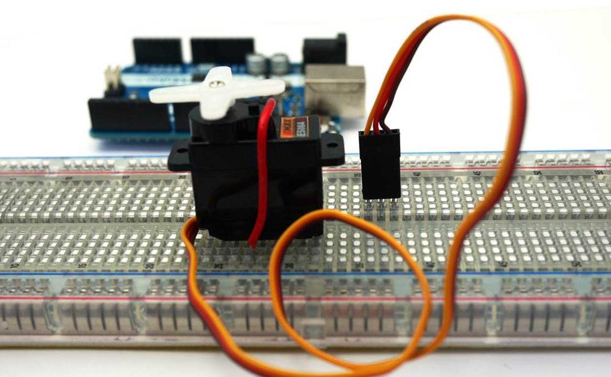
Figure 3-4. Modified servo motor wire connector inserted into the full-size clear breadboard
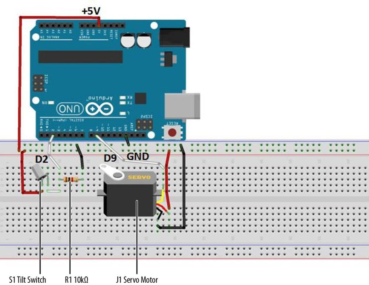
Figure 3-5. Tilt Sensing Servo Motor Controller Fritzing diagram
Upload the Tilt Sensor Sketch
With the Tilt Sensing Servo Motor Controller circuit built on the full-size clear breadboard, it’s time to upload the sketch:
1. Attach the Arduino to your computer using a USB cable.
2. Open the Arduino software and type Example 3-1 into the software’s text editor.
3. Upload the sketch to the Arduino.
4. Rotate the tilt control switch back and forth. The servo motor will spin in the same direction as the tilt control switch orientation.
TROUBLESHOOTING TIP
Rotate the tilt control switch slowly and smoothly to get the best response from the servo motor.
Example 3-1. Tilt Control Switch sketch
/* This sketch controls a servo motor using a tilt control switch!
*
* 12 December 2012
* by Don Wilcher
*
*/
#include<Servo.h> // include Servo library
int inPin = 2; // the tilt control switch is wired to Arduino D2 pin
int reading; // the current reading from the input pin
Servo myservo; // create servo motor object
void setup()
{
myservo.attach(9); // attach servo motor to pin 9 of Arduino
pinMode(inPin, INPUT); // make pin 2 an input
}
void loop()
{
reading = digitalRead(inPin); // store digital data in variable
if(reading == HIGH) { // check digital data with target value
myservo.write(180); // if digital data equals target value,
// servo motor rotates 180 degrees
delay(15); // wait 15ms for rotation
}
else { // if reading is not equal to target value,
myservo.write(0); // rotate servo motor to 0 degrees
delay(15); // wait 15ms for rotation
}
}
A Simple Animatronic Controller Using the Serial Monitor
Tilt control switching can be used in a variety of human machine control and physical computing applications. In the theater, electromechanical puppets are often controlled using electronic sensors and servo motors. The tilt control switch project you built can be used as a simple animatronic controller. Example 3-2 shows an improved Arduino sketch that limits the servo motor rotation to 90° and adds Serial Monitor output for displaying information about the tilt control switch. Figure 3-6 shows the tilt control switch digital data.
TECH NOTE
Physical computing allows people to interact with objects using electronics, software, and sensors.

Figure 3-6. Digital data from tilt control switch: open tilt control switch (left), closed tilt control switch (right)
Example 3-2. Tilt Control Switch with Serial Monitor
/* This sketch controls a servo motor using a tilt control switch!
* Serial Monitor displays digital data from Tilt Control Switch.
*
* 15 December 2012
* by Don Wilcher
*
*/
#include<Servo.h> // include Servo library
int inPin = 2; // the Arduino input pin tilt control switch is wired to D2
int reading; // the current reading from the input pin
Servo myservo; // create servo motor object
void setup()
{
myservo.attach(9); // attach servo motor to pin 9 of Arduino
pinMode(inPin, INPUT); // make pin 2 an input
Serial.begin(9600); // open communication port
}
void loop()
{
reading = digitalRead(inPin); // store digital data in variable
if(reading == HIGH) { // check it against target value (HIGH)
myservo.write(90); // if digital data equals target value,
// servo motor rotates 90 degrees
Serial.println(reading); // print tilt control switch digital data
delay(15); // wait 15ms for rotation
}
else { // if it's not equal to target value...
myservo.write(0); // rotate servo motor to 0 degrees
Serial.println(reading); // print tilt control switch digital data
delay(15); // wait 15ms for rotation
}
}
Experiment with the different rotation angle values and observe the servo motor’s behavior. Happy puppetry!
The block diagram in Figure 3-7 shows the electronic component blocks and the electrical signal flow for the Tilt Sensing Servo Motor Controller. A Fritzing electronic circuit schematic diagram of the controller is shown in Figure 3-8. Electronic circuit schematic diagrams are used by electrical/electronic engineers to design and build cool electronic products for society.
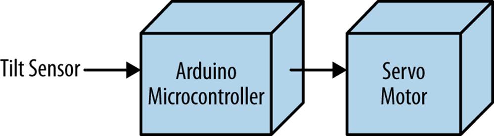
Figure 3-7. Tilt Sensing Servo Motor Controller block diagram
TECH NOTE
Always document your experiments and design changes in a lab notebook in case you develop that million dollar idea!
OBSERVING THE SWITCH’S BEHAVIOR
If you have or know someone who has a DMM (digital multimeter), attach your tilt control switch to it. Set the DMM to read resistance. By changing the orientation of the tilt control switch, you will see the internal pins open and close based on the changing resistance value. A closed tilt control switch has a DMM resistance reading of zero ohms. An open tilt control switch has an infinite resistance value displayed on the DMM. The pins’ switching conditions are used to rotate a servo motor. In the Tilt Sensing Servo Motor Controller project, directional movement will occur by orientation of the sensor circuit.
Note that an infinite resistance reading may be displayed as O or 1 on a DMM.
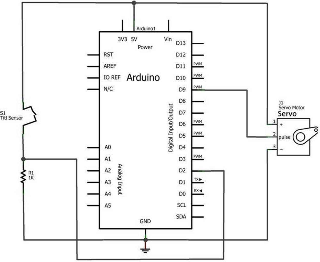
Figure 3-8. Tilt Sensing Servo Motor Controller circuit schematic diagram: orange wire (D9), red wire (+5V), and brown wire (GND)
Circuit Theory
A tilt control switch is an electrical device used to detect orientation. Like using a mini pushbutton and a light detector, a tilt control switch is another way to interact with and control the Arduino.
The tilt control switch is a pair of small metal balls that make contact with pins and close the circuit when the electrical device is held in an upright position. Figure 3-9 shows a typical tilt control switch. The tilt control switch can be wired to a resistor to make an orientation detection sensor circuit.
Figure 3-10 shows an orientation detection sensor circuit and its electrical operating conditions. The Arduino’s D2 pin is wired to the 1KΩ resistor in order to receive either a zero or five volt control signal, based on the tilt control switch orientation. With the tilt control switch pins open, the voltage across the 1KΩ resistor is zero volts. When the switch pins are closed, the 1KΩ resistor has a five volt signal across it.
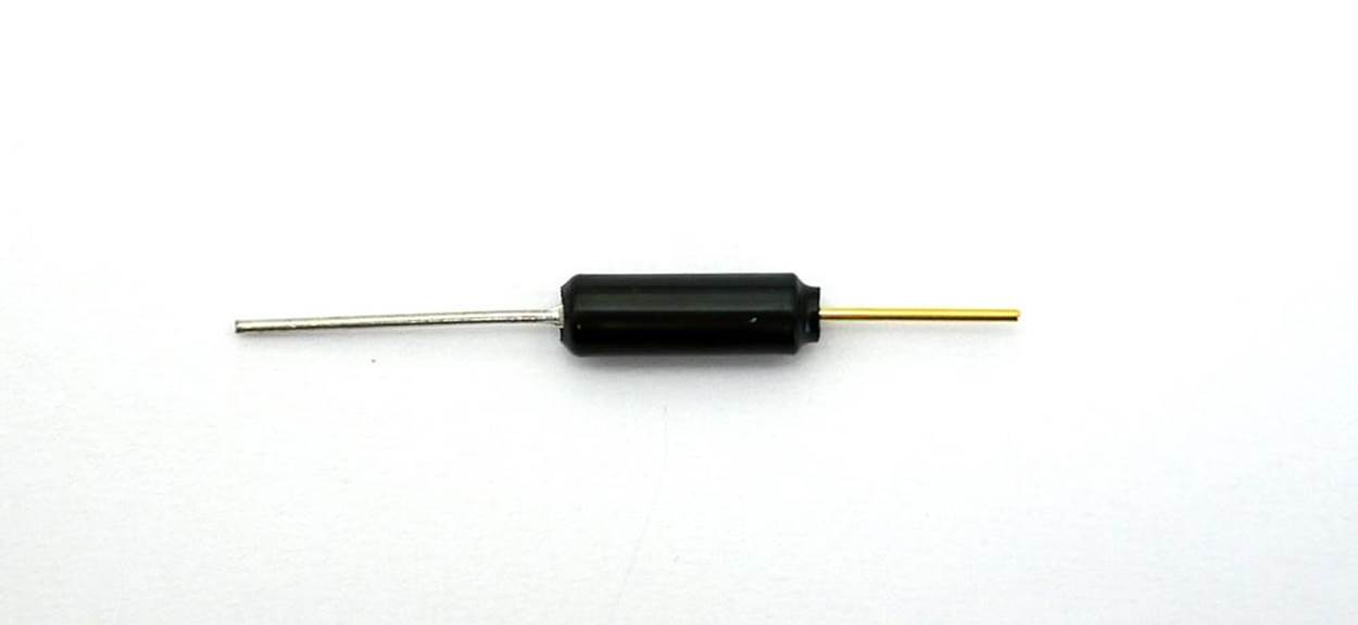
Figure 3-9. Typical tilt control switch
TECH NOTE
As you rotate the tilt control switch, you can actually hear the small metal balls move around.
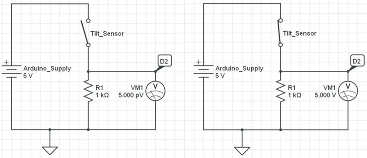
Figure 3-10. Orientation detection sensor operation: open tilt control switch (left), closed tilt control switch (right)
TECH NOTE
Tilt sensor is another name used for tilt control switch.
Something to Think About
How could the words “up” and “down” for the tilt sensor orientation be displayed on the Serial Monitor?
All materials on the site are licensed Creative Commons Attribution-Sharealike 3.0 Unported CC BY-SA 3.0 & GNU Free Documentation License (GFDL)
If you are the copyright holder of any material contained on our site and intend to remove it, please contact our site administrator for approval.
© 2016-2026 All site design rights belong to S.Y.A.