Make: Basic Arduino Projects - 26 Experiments with Microcontrollers and Electronics (2014)
Chapter 4. Twin LEDs
LEDs in Parallel
LEDs can be used to light objects or to alert the user about the operating conditions of a device. Light-emitting diodes are easy to use and they come in a variety of shapes, sizes, and colors, as shown in Figure 4-1. The Arduino has a dedicated tiny LED wired to pin D13. By uploading the Blink sketch to the Arduino, you can check its electrical operation. Unlike the ordinary light bulb, LEDs must be wired properly for them to work. In this chapter, you will learn how to wire two LEDs to the Arduino, as shown in the block diagram in Figure 4-2. The LED projects in this chapter will also use the Ultimate Microcontroller Pack’s MakerShield. To add a little creativity to the LED projects, you will learn how to build an interactive toy using an ordinary piece of cardboard.
Parts List
§ Arduino microcontroller
§ MakerShield kit
§ R1: 330 ohm resistor (orange, orange, brown stripes)
§ R2: 330 ohm resistor (orange, orange, brown stripes)
§ R3: 10K ohm potentiometer
§ R4: photocell
§ R5: 1K ohm resistor (brown, black, red stripes)
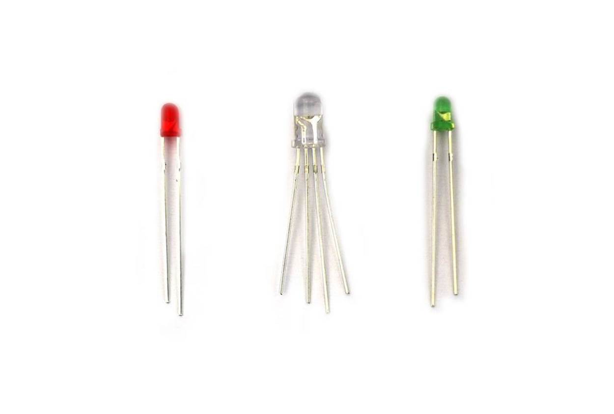
Figure 4-1. Variety of LEDs
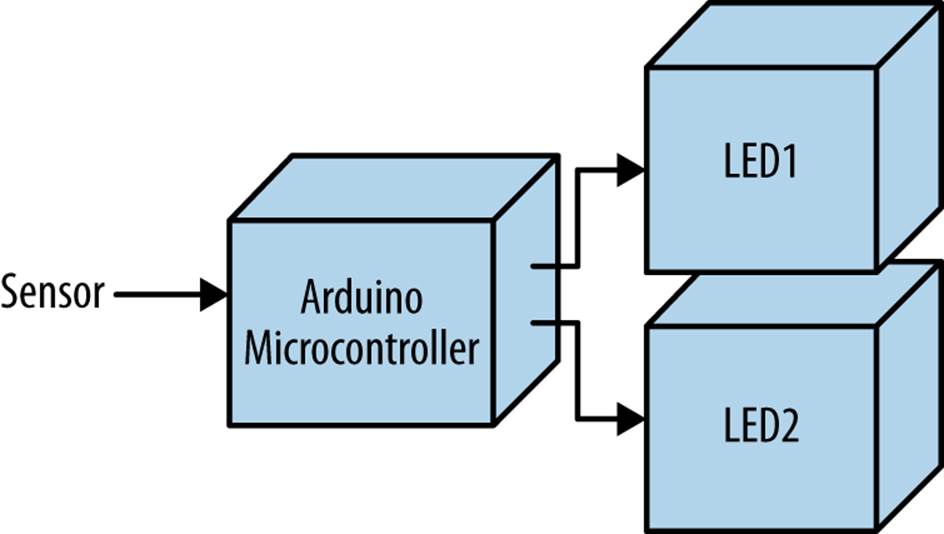
Figure 4-2. Twin LEDs block diagram
Circuit Theory
An LED is an electronic part that emits light when properly wired in an electric circuit. The LED has positive and negative leads protruding through a plastic body, as shown in Figure 4-1. You can use the Arduino in electronic projects to operate multiple LEDs. Figure 4-3 shows two LEDs wired to the Arduino D13 pin. The Arduino output pins are capable of providing 40 mA (milliamperes) of electrical current, sufficient to turn on two LED circuits wired in parallel.
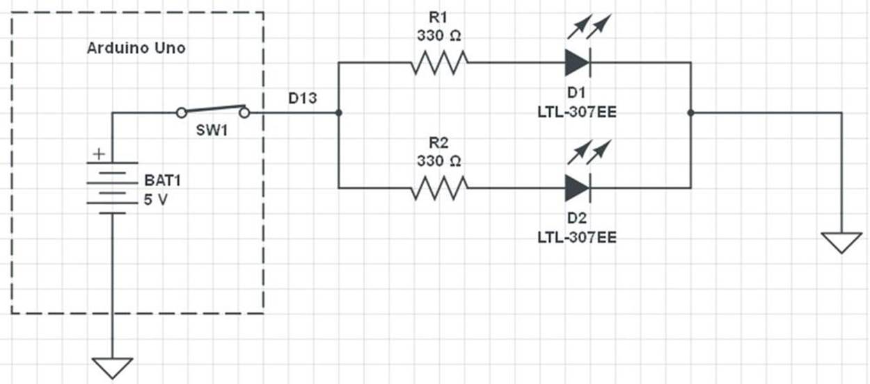
Figure 4-3. Two LED circuits wired in parallel to the Arduino D13 pin; the arrows indicate the LEDs are on
Twin LED Flasher
The circuit theory diagram shown in Figure 4-3 can easily be converted into a cool electronic gadget. You can build a Twin LED Flasher using an Arduino, two 330 ohm resistors, and LEDs, as shown in Figure 4-4. The Twin LED Flasher circuit schematic diagram is shown in Figure 4-5. To make the flasher device compact, you can build it on the MakerShield, as shown in Figure 4-6. Uploading the Blink sketch to the Arduino allows you to test the MakerShield and the Twin LED Flasher. The Blink sketch for the electronic flasher is shown in Example 4-1.
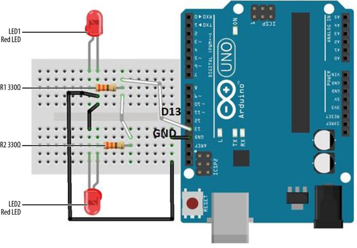
Figure 4-4. Twin LED Flasher Fritzing diagram
TECH NOTE
The omega symbol (Ω) and the word ohm are used interchangeably. For example, 10KΩ, 10K, and 10K ohm indicate the same value.
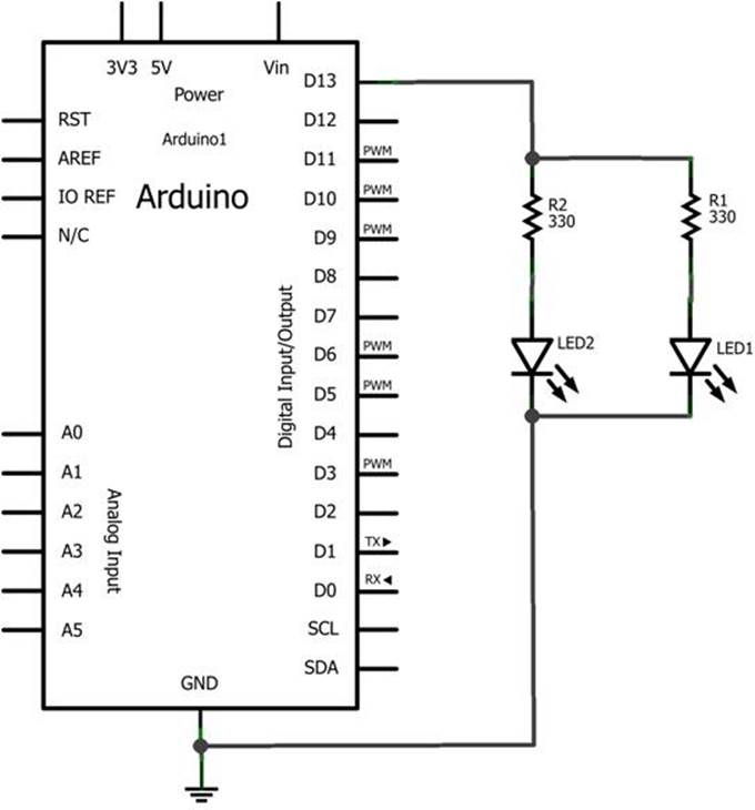
Figure 4-5. Twin LED Flasher: LED1 and LED2 with 330 ohm resistors are wired in parallel to the Arduino D13 pin
TECH NOTE
The Build a MakerShield guide, part of Make: Projects, includes step-by-step directions for building your own prototyping shield.
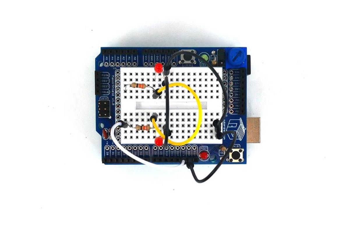
Figure 4-6. MakerShield Twin LED Flasher
Example 4-1. Blink sketch
/*
Blink
Turns on an LED on for one second, then off for one second, repeatedly.
This example code is in the public domain.
*/
// Pin 13 has an LED connected on most Arduino boards.
// give it a name:
int led = 13;
// the setup routine runs once when you press reset:
void setup() {
// initialize the digital pin as an output:
pinMode(led, OUTPUT);
}
// the loop routine runs over and over again forever:
void loop() {
digitalWrite(led, HIGH); // turn the LED on (HIGH is the voltage level)
delay(1000); // wait for a second
digitalWrite(led, LOW); // turn the LED off by making the voltage LOW
delay(1000); // wait for a second
}
Build the Adjustable Twin LED Flasher
To make the Adjustable Twin LED Flasher, simply add a 10K ohm potentiometer to the device. The flash rate can be adjusted to make the on/off toggling slower or faster. The Fritzing diagram in Figure 4-7 along with the circuit schematic diagram shown in Figure 4-8 will allow you to build the Adjustable Twin LED Flasher. The MakerShield Adjustable Twin LED Flasher is shown in Figure 4-9 and the Adjustable Twin LED Flasher sketch is shown in Example 4-2.
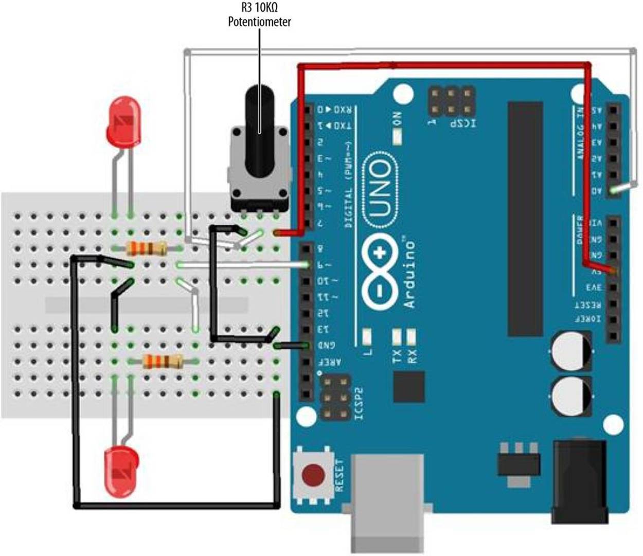
Figure 4-7. Adjustable Twin LED Flasher Fritzing diagram
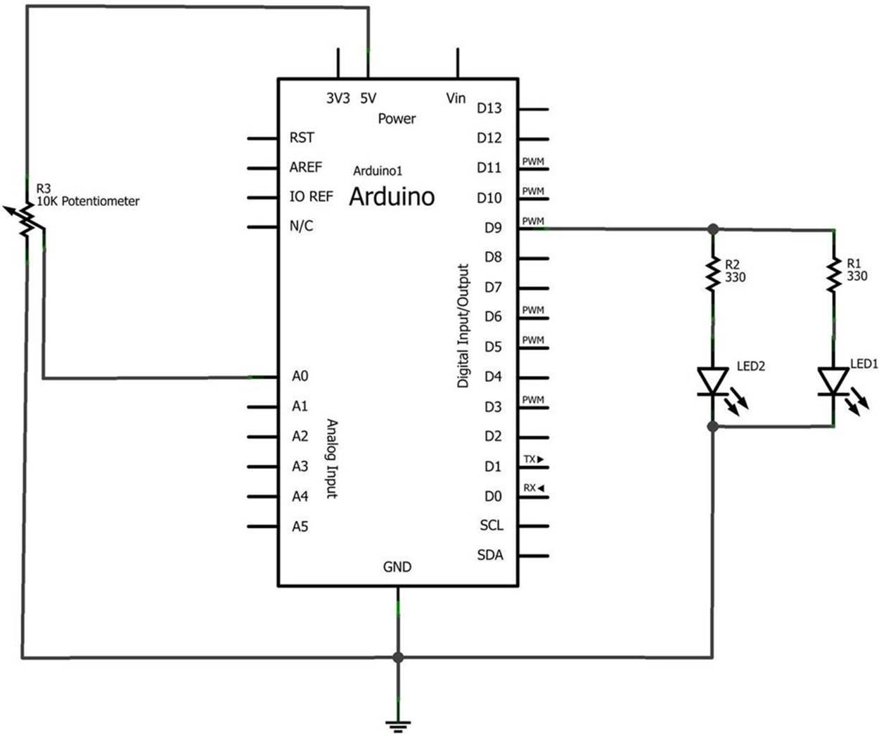
Figure 4-8. Adjustable Twin LED Flasher circuit schematic diagram
Example 4-2. Adjustable Twin LED Flasher sketch
/*
Adjustable Twin LED Flasher
Two LEDs will flash at a specified rate
based on the 10K potentiometer setting.
01 Jan 2013
by Don Wilcher
*/
// Two LEDs with 330 ohm series resistors wired
// in parallel connected to pin 9.
int led = 9; // pin D9 assigned to led variable.
// A 10K potentiometer center pin wired to pin A0.
// One pin is wired to +5V with the other connected to GND.
int PotIn = A0; // pin A0 assigned to PotIn variable.
int Flash; // Flash variable to be used with "delay" instruction.
// the setup routine runs once when you press reset:
void setup() {
// initialize the digital pin as an output:
pinMode(led, OUTPUT);
// initialize the analog pin as an input:
pinMode(PotIn, INPUT);
}
// the loop routine runs over and over again forever:
void loop() {
Flash =analogRead(PotIn); // read 10K pot, store value in Flash variable
digitalWrite(led, HIGH); // turn the LED on (HIGH voltage level = on)
delay(Flash); // wait for a Flash time delay in seconds
digitalWrite(led, LOW); // turn the LED off by making the voltage LOW
delay(Flash); // wait for a Flash time delay in seconds
}
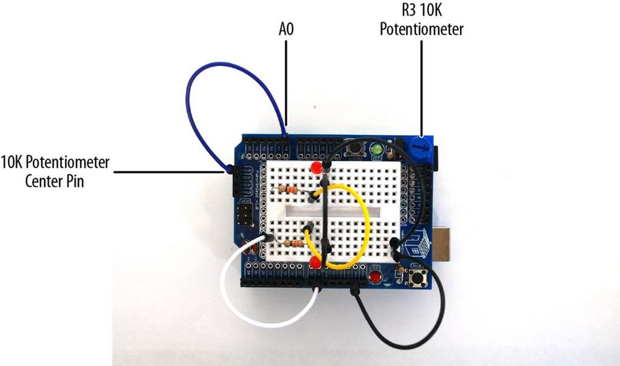
Figure 4-9. MakerShield Adjustable Twin LED Flasher
It’s Alive! Build a FrankenBot Toy
You can build an interactive toy that responds to changing light levels by removing the 10KΩ potentiometer and adding a photocell wired to a 1KΩ resistor of the Adjustable Twin LED Flasher. Wiring a photocell to a 1KΩ resistor allows the Arduino to read light levels applied to pin A0.Figure 4-10 and Figure 4-11 show the Fritzing and circuit schematic diagrams for the Interactive Twin LED Flasher. The MakerShield Interactive Twin LED is shown in Figure 4-12.The photocell leads are bent down to allow FrankenBot’s cardboard head to mount nicely on top of the MakerShield, as shown in Figure 4-13.
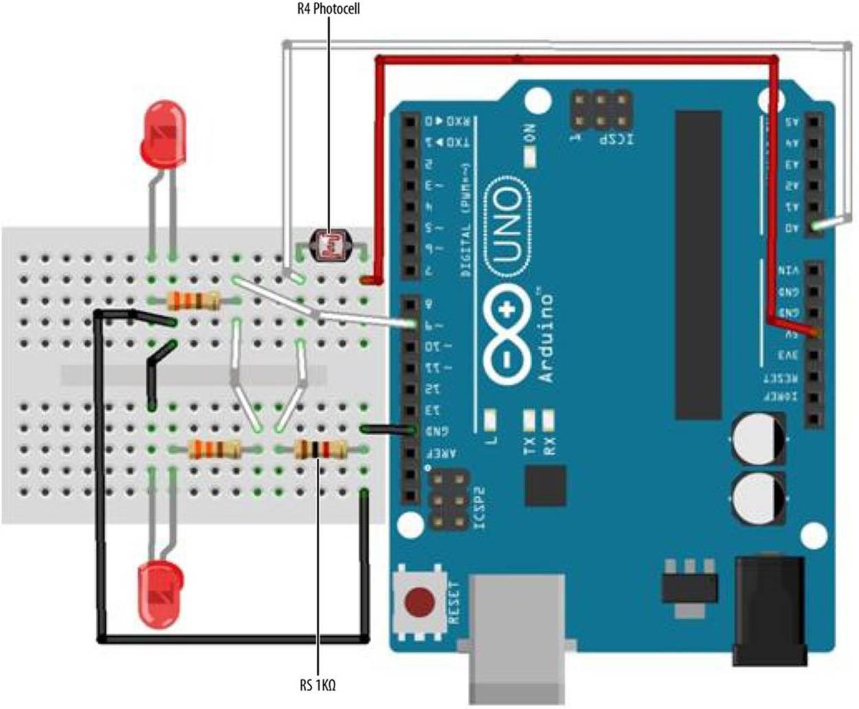
Figure 4-10. Interactive Twin LED Flasher Fritzing diagram
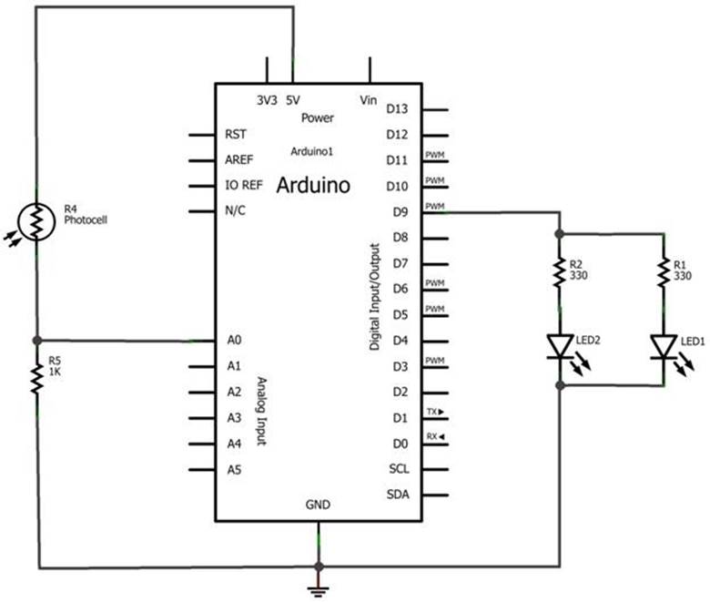
Figure 4-11. Interactive Twin LED Flasher circuit schematic diagram
The Adjustable Twin LED Flasher sketch shown in Example 4-2 is used to read the different light levels and change the Arduino’s output flash rate.
TECH NOTE
Check out my YouTube clip to see the FrankenBot in action.
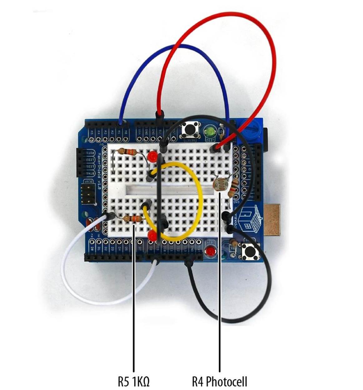
Figure 4-12. Makershield Interactive Twin LED Flasher
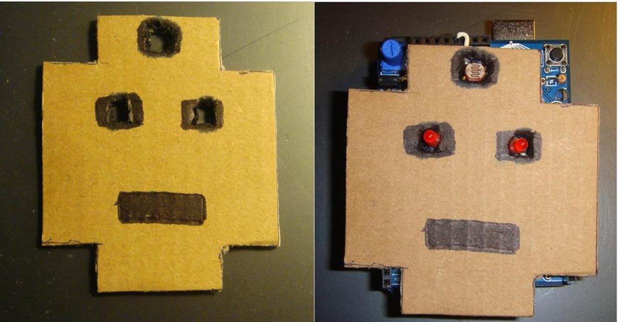
Figure 4-13. FrankenBot: cut out opening for the photocell and LEDs to pass through cardboard FrankenBot head (left); mount cardboard Frankenbot head on top of MakerShield Interactive Twin LED Flasher (right)
TECH NOTE
The FrankenBot head template can be found on my Arduino Downloads page.
With the Example 4-2 sketch uploaded to the Arduino, FrankenBot’s LEDs will be flashing at a rate based on the surrounding lighting conditions. Place your hand over the photocell and watch the LEDs flash faster. Try different light sources and notice the effect on FrankenBot’s LEDs. As always, record your tests and experiments in a lab notebook!
TROUBLESHOOTING TIP
Check your wiring, the placement of the electronic parts on the breadboard, and the photocell bent leads if the Twin LED Flasher is not working.
Something to Think About
Why are FrankenBot’s LEDs affected by the changes in lighting conditions or sources?