Arduino Sketches: Tools and Techniques for Programming Wizardry (2015)
Part II. Standard Libraries
Chapter 10. WiFi
This chapter discusses the following functions of the WiFi library:
· begin()
· macAddress()
· BSSID()
· RSSI()
· scanNetworks()
· SSID()
· encryptionType()
· disconnect()
· config()
· setDNS()
· WiFiClient()
· WiFiServer()
The hardware needed to use these functions includes:
· Arduino Uno
· SainSmart WiFi shield
· DHT11 humidity and temperature sensor
· Breadboard
· Wires
· 10 kilohm resistor
You can find the code download for this chapter at http://www.wiley.com/go/arduinosketches on the Download Code tab. The code is in the Chapter 10 folder and the filename is chapter10.ino.
NOTE
The Wireless technology name is Wi-Fi with a hyphen, but in the Arduino library, where it is unable to use hyphens, it is called WiFi. For this chapter, Wi-Fi refers to the technology, and WiFi to the Arduino library capable of using WiFi cards.
Introduction
All aspects of computers have evolved at an incredible rate. A high-end computer from 10 years ago is, by today's standard, easily surpassed by a mobile telephone. Processors, memory, and storage have all increased, and component size has drastically decreased. Mobile computers used to be rare; today, laptop computers are seen just about everywhere, as are tablets, smartphones, and even smart watches. The need for mobility has been driving the industry for years, but the need for data even more so.
Early networks were slow, complicated, cabled systems. Today, Ethernet technology can be found in almost every house. On the back of most Internet modems is a small Ethernet switch, providing four or more “ports”; connecting a computer is as simple as plugging an Ethernet cable in the ports. To add another computer, just plug in another cable in the next open port. This is perfect for households, and the same technology also powers huge companies with thousands of computers, including the Internet. Networks have become fast and reliable, but until recently, the need for physical wiring conflicted with mobility.
Mobile users had data on the go. Commercial teams could have documents on their computer with them, and engineers could have development tools and diagnostics with them. However, to get access to the Internet, or even to transfer documents, they had to plug in their laptop to the company's network. Most meeting rooms had an Ethernet switch with a few cables, just in case anyone needed quick access. Mobile devices would never be truly mobile until they got rid of the cables tethering them to the desk, and so Wi-Fi was born.
The WiFi Protocol
Wi-Fi standard devices use a wireless local area network (LAN). The technology is managed by the Wi-Fi Alliance, a group of some of the leading companies in wireless and networking products that did not actually create the technology itself.
In 1985, the U.S. Federal Communication Commission opened up part of the wireless spectrum for unlicensed use. The original wireless protocol was called WaveLAN, developed by NCR for cashier systems. The radio portion was hidden from operating systems, and to the drivers, WaveLAN cards were talking together via wired systems, making installation and use extremely easy.
Its successor, 802.11, was created in 1997. It had a data-rate of either 1 or 2 megabits per second and a communications distance of 60 feet. Interoperability problems were detected, notably because the Institute of Electrical and Electronics Engineers (IEEE for short) creates standards but does not test them for certification. The original 802.11 was not widely embraced, but a new version was: 802.11b. With the birth of 802.11b came the Wireless Ethernet Compatibility Alliance (WECA), which proposed rigorous certification programs. All devices sold with a Wi-Fi logo were compatible, and consumers loved the technology. WECA later changed its name to the Wi-Fi Alliance.
802.11b gave much faster data rates: 1, 2, 5.5, and 11 megabits per second. Although these speeds were good for browsing the web, they were not fast enough for video streaming or heavy data transfer. 802.11g proposed data rates of up to 55 Mbit/s, while retaining 802.11b compatibility. (When talking to an 802.11b device, the speed would be at a maximum of 11 Mbit/s). Newer versions provide even faster data rates; 802.11n can go as fast as 150 Mbit/s; 802.11ac can go up to 866.7 Mbit/s; and 802.11ad can transfer data at a staggering 6.75 Gbit/s.
Topology
Wi-Fi works with several network topologies, but there are two main types that are used: ad-hoc and infrastructure.
Ad-hoc mode is an unmanaged, decentralized mode. Wireless peers are free to connect to other peers, and the network is managed by all the peers. Wireless devices maintain network connectivity by forwarding packets to other devices when needed. All network peers have an equal status, and the network is only as reliable as the parameters of the hosts (transmit power, interference, and link-length). Ad-hoc networks are often closed networks; peers cannot always communicate outside the network.
Infrastructure mode is a managed mode. This topology requires one or several devices to “manage” the network, allowing peers to connect to it (or refuse connection depending on the security settings). Peers do not communicate between themselves; instead they send their packets to the network management devices: typically access points. Infrastructure access points often serve as access points to other networks: typically a wired network or a connection to the Internet. Multiple access points can be on a wired network, allowing for several zones, or “hot spots” where peers can connect wirelessly.
Network Parameters
For a network to function, several parameters are required. Imagine an apartment block—several neighbors are within close range. Each family has an Internet connection, and each family also wants access to wireless for their laptops, tablets, and mobile phones. Each family also wants their devices to be private. Instead of creating one large wireless network, each family wants its own small wireless network. It also wants it to work securely and efficiently, while allowing neighbors access to their wireless networks.
Channels
Wi-Fi works with two base frequencies: 2.4 GHz and 5 GHz. However, in practice, there are several frequencies; the 2.4-GHz band operates from 2.412 GHz all the way to 2.484 GHz. This spectrum is separated into different frequencies, or channels. If all wireless devices used exactly the same frequency, that frequency would soon become saturated as small networks started competing with other networks. Also, Wi-Fi is not the only wireless technology to use the 2.4 GHz band. For example, Bluetooth also uses these frequencies. To help, Wi-Fi uses channels.
A channel is a specific frequency used by one particular wireless network. Channels work in the same way as your television; information is received wirelessly and picked up through the TV antenna. By selecting a particular channel, you decide to listen to one particular frequency in the range, therefore excluding all other channels. When you finish watching a program, you can switch to another channel, receiving the information on one channel at a time. Wi-Fi channels work almost the same way except that channels can overlap each other. Each wireless controller (an Internet modem or access point) is configured to use a particular channel. Some analyze the network before initializing and automatically choose a free channel.
Encryption
Although most people don't think much about it, Wi-Fi presents a problem. You might be at home, shopping on your favorite Internet site. After you choose the articles you want, you go to pay, entering in your debit card details. Wireless information can, theoretically, be seen by anyone. Just like a regular conversation, if the person is close enough to hear, then he can get access to that information. To avoid this, infrastructure wireless communications are normally encrypted. Anyone can listen in to your conversation with your favorite Internet site but will not be able to understand because that conversation is encrypted with a special key that others do not know.
There are two forms of encryption: WEP and WPA2. WEP (short for Wireless Equivalent Privacy) is an early form of wireless encryption. Today, the standard is outdated, and Wi-Fi networks are encouraged to use the newer WPA2 encryption.
WPA2 (short for Wi-Fi Protected Access 2) is a solution to the weaknesses found in WEP and is a stronger version of the previous WPA encryption. It enables strong 256-bit AES encryption, using either 64 hexadecimal characters or 8 to 63 printable ASCII characters as a passkey. Again, several versions exist, but two main versions are used: WPA2 Personal and WPA2 Enterprise. WPA2 Personal requires a passkey and is perfect for home or small office environments. WPA2 Enterprise requires a specialized server and protects against more advanced attacks.
Not only does the encryption secure communications, it also secures the network. A wireless device that does not have the password cannot connect.
SSID
The network SSID, short for Service Set ID, is essentially the “network name,” as it is known. This is the name that displays when you refresh your wireless network list, and is the name that devices attempt to connect to. SSIDs are sometimes hidden but are always present. A hidden SSID works in exactly the same way, only the name is not broadcast to devices; devices can still attempt to connect to a hidden SSID.
RSSI
RSSI is short for Received Signal Strength Indication and is an indication of signal strength. The units are arbitrary; some devices report signal strength as a percentage, others as a unit called dBm, or decibels per milliwatt of power. Reading this value gives an indication of signal strength and not distance because signal strength can be altered by physical obstructions (like walls) or electromagnetic interference.
Arduino WiFi
The Arduino WiFi library is designed to work with a large amount of network controllers through a simple system. The WiFi library “talks” to the Wi-Fi shield through the SPI bus, and communication is normally handled with a small microcontroller, “translating” messages on the SPI bus to the network controller.
Several vendors manufacture Wi-Fi shields, and there is also an official Arduino shield. Each board has its strong points: external antenna connectors, ultra-low power, and bridging possibilities. It all depends on your project. This chapter talks about standard connections without any external components or antennae.
The WiFi library can connect to a variety of Wi-Fi standards: typically B, G, and N networks. It can handle both WEP and WPA-2 Personal encryption but cannot connect to a WPA-2 Enterprise network. Also, it cannot connect to hidden SSIDs.
The WiFi library uses the SPI bus and requires the SPI pins to be free. It uses pins 11, 12, and 13 on the Arduino Uno, and 50, 51, and 52 for the Arduino Mega. Pin 10 is used as a Slave Select pin, and pin 7 is used as a digital handshake; these pins should not be used by the rest of the sketch.
The WiFi library methods are similar to those in the Ethernet library, and many of the functions are identical—only changed slightly to handle wireless networks and the subtle differences they face.
CROSS-REFERENCE
Ethernet is presented in Chapter 9.
Importing the Library
To use the WiFi library, it must first be imported, which you can do in the Arduino IDE (menu Sketch ![]() Add Library
Add Library ![]() WiFi) or by adding the library manually:
WiFi) or by adding the library manually:
#include <WiFi.h>
You need to import other libraries, depending on your project:
#include <WiFiServer.h>
#include <WiFiClient.h>
#include <WiFiUdp.h>
The WiFiServer.h header file is used if the Arduino is to be a server. If a client connection is going to be made, the WiFiClient.h header file should be used. The WiFiUdp.h library should be imported if UDP communications are to be used.
Initialization
To initialize the WiFi subsystem, you must use begin(). It can take several parameters, depending on your configuration. To start the WiFi subsystem without any parameters (network SSID, password), just call begin():
WiFi.begin();
To connect to an open SSID (one that does not require a password), use only the ssid parameter:
WiFi.begin(ssid);
To connect to a WPA-2 Personal protected network, specify the SSID and the password:
WiFi.begin(ssid, password);
To connect to a WEP protected network, another parameter is required. WEP protected networks can have up to four keys, and you must specify which one to use:
WiFi.begin(ssid, keyIndex, key);
Both keys and SSIDs can be written as an array of chars:
char ssid[] = "yourNetworkSSID";
char password[] = "MySuperSecretPassword";
Status
Of course, initialization presumes that a WiFi shield is present and correctly connected, which might not always be the case. To test for a WiFi shield, use the status() function:
result = WiFi.status();
This function takes no parameters and returns one of several constants, as shown in Table 10.1.
Table 10.1 Status Update Return Codes
|
Constant |
Meaning |
|
WL_IDLE_STATUS |
The WiFi shield is idle, without any instructions. |
|
WL_NO_SSID_AVAIL |
There are no networks to connect to. |
|
WL_SCAN_COMPLETED |
An initial SSID scan has been completed, and the WiFi shield knows about available SSIDs. |
|
WL_CONNECTED |
The WiFi shield has successfully connected to an SSID. |
|
WL_CONNECT_FAILED |
The WiFi shield was unable to connect; either the encryption key is wrong, or the connection was refused by the access point. |
|
WL_CONNECTION_LOST |
The WiFi shield was previously connected, but that connection has been lost (either out of range, or interference). |
|
WL_DISCONNECTED |
The WiFi shield has successfully disconnected from a network. |
|
WL_NO_SHIELD |
The Arduino cannot find a WiFi shield connected to the board. |
Unlike Ethernet shields, WiFi shields have a fixed MAC address. To know the MAC address of the WiFi shield, use macAddress(). This function does not return any data but requires a parameter: a 6-byte array in which the MAC address will be placed.
byte mac[6];
WiFi.macAddress(mac); //Retrieve the MAC address, place it in mac
To retrieve the MAC address for the access point you are connected to, use BSSID():
WiFi.BSSID(bssid);
Just like the macAddress() function, this function does not return any data but requires a data container as a parameter: a 6-byte array in which the MAC address will be placed.
To retrieve the RSSI, the signal quality indicator, use the RSSI() function:
long result = WiFi.RSSI();
RSSI, short for Received Signal Strength Indication, is a measurement of power in received radio signals. It is an indicator that generally goes from −100 to 0; the closer to 0, the stronger the reception. It cannot be used to estimate the range of a wireless device since interference can come not only from range, but also from electronic equipment or walls.
Scanning Networks
Due to the mobile nature of wireless, it can be helpful to scan the wireless networks around you to know which to connect to. An Arduino in a car might automatically connect to a home network when it's in range to send diagnostic information on your car but might also be configured to connect to another network, for example, a friend's house. In this case, the Arduino needs to periodically scan the available wireless networks until it finds one it recognizes. Wireless scanning on computers is frequent; open your wireless configuration panel to see a list of available networks.
To initiate a scan, use scanNetworks():
result = WiFi.scanNetworks();
This function takes no parameters and returns an int—the number of wireless networks detected. A scan can take a few seconds to complete, but when done, the results are stored on the wireless chip, ready for interrogation. The chip stores several pieces of information: the SSID name, the signal strength, and the encryption type.
To retrieve the SSID of a network, use SSID():
result = WiFi.SSID(num);
It takes one parameter: the number of a network scanned with the scanNetworks() function. It returns a String: the name of the SSID.
To know the RSSI of a station broadcasting, use RSSI() specifying the network number:
result = WiFi.RSSI(num);
Exactly like RSSI() used to learn the RSSI of the current network, this function returns a long, the value in dBm, short for Decibel-milliwatts. Typical values range from −80 to 0; the higher the number, the better the reception.
Wireless networks also broadcast their security, specifically the encryption method required to connect (if any). To know the encryption of a network, use encryptionType(), specifying the network number:
result = WiFi.encryptionType(num);
This function returns a constant: the type of encryption detected. Table 10.2 lists the values.
Table 10.2 Possible Encryption Types
|
Value |
Meaning |
|
ENC_TYPE_WEP |
WEP encryption |
|
ENC_TYPE_TKIP |
WPA encryption |
|
ENC_TYPE_CCMP |
WPA2 encryption |
|
ENC_TYPE_NONE |
No encryption, open network |
|
ENC_TYPE_AUTO |
Multiple encryption methods possible |
Connecting and Configuring
To connect to a wireless network, use begin(), explained previously in the “Initialization” section. To disconnect from a network, use disconnect():
WiFi.disconnect();
This function does not take any parameters and does not return any information. It immediately disconnects from the current network.
By default, the WiFi shield uses DHCP to obtain an IP address and network settings. When begin() is called, DHCP negotiations begin after connecting to the network. While some wireless networks provide DHCP, others do not and require manual configuration. To perform manual configuration, use config(). This function can be called in four ways:
WiFi.config(ip);
WiFi.config(ip, dns);
WiFi.config(ip, dns, gateway);
WiFi.config(ip, dns, gateway, subnet);
In its most basic form, config() requires one parameter: the IP address to use, expressed as an array of 4 bytes, or optionally, using an IPAddress object. This object takes 4 bytes; the 4 bytes of an IP Address:
IPAddress ip(192.168.0.10);
To translate human-readable text into IP addresses, a Domain Name Server must be specified as the dns parameter, again, as an array of 4 bytes, or IPAddress. For packets to leave the current network to another network, a gateway IP must be specified with gateway. Finally, to change subnet, you must specify the subnet IP (by default: 255.255.255.0).
Calling config() before begin() forces the WiFi shield to use the settings specified. Calling config() after begin() again forces the WiFi shield to use the settings that were specified, but the begin() function will attempt to contact a DHCP server beforehand, resulting in a possible IP change.
The downside to this is that to use a specific DNS, you must specify the IP address. Some computers prefer to use an external DNS. (For example, Google allows users to use their DNS instead of their Internet provider's DNS.) To remedy this, the setDNS() function can be used.
WiFi.setDNS(dns_server1);
WiFi.setDNS(dns_server1, dns_server2);
This function requires either one or two DNS server addresses. It returns no data and immediately sets the DNS server values without changing the IP address.
Wireless Client
Just like with the Ethernet library, the WiFi library has its own client class. Remember, a client is a device that connects to a server on a specified port. A server is always on listening for client connections.
Before connecting to a server, the client must first create a client object; for the WiFi library, this is called WiFiClient.
// Initialize the client library
WiFiClient client;
This library is almost identical to the Ethernet library, though certain technical aspects are different to handle wireless connectivity. To create a socket to a server, you must use connect(), just like with the Ethernet library:
result = client.connect(server, port);
The function takes two parameters: port is an int and indicates the port to which you want to connect. The server parameter is either an IPAddress (or an array of 4 bytes), or a String containing the server name. It returns a boolean:true if the connection was accepted, and false if the connection failed.
Wireless Server
Wireless devices can also be servers, waiting for clients to connect before answering to requests. Again, the WiFi library has its own specialized object: WiFiServer:
WiFiServer server(port);
The port parameter is the port that you want to open, expressed as an int. When the port is opened, the server waits for incoming connections with begin():
server.begin(); // Wait for clients to connect
Example Application
I'm terrible with plants. Taking care of most kinds isn't that complicated; I just need to keep the dirt moist, keep them out of direct sunlight (but still enough sunlight) and change the dirt from time to time. Just keeping the dirt moist seems to be too much for me, and this is where technology can help.
The DHT11 is a popular temperature and humidity sensor; it is inexpensive, reliable, and fairly easy to use. It comes with a plastic cover offering protection from most environments, and as long as you don't put water directly onto it, it can live happily with your houseplants. It is illustrated in Figure 10.1.
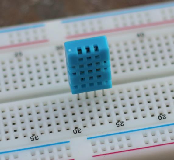
Figure 10.1 The DHT11
The DHT11 does have something unique. Previous chapters talked about serial communications, some of them requiring more wires than others, but some (I2C especially) requiring only two wires to function. This component is different; it requires only one. There is one wire used to send and to receive data, in addition to a power and ground. Although it might sound complicated to use a single wire for both data reception and emission, it is actually fairly straightforward. The downside to this component is that you can make only one reading every 2 seconds, but that is more than enough for a houseplant, even mine.
This application uses an Arduino Uno and a SainSmart wireless shield. A DHT11 sensor will be connected to the board, allowing the user to get an accurate reading. Because I'm terrible with plants, I probably won't check the reading frequently, so this device must communicate with the outside world to send alerts. It will monitor the humidity of the dirt and send e-mails when the humidity level drops below a certain level. For this, it must be connected to the Internet. Because I don't have a wired access point nearby, I'll be using a wireless network.
This project requires a certain number of services to be put in place. First, it requires a DHCP server on the current network. Most Internet modems have their own DHCP server, so it should be compatible with most wireless access points. Secondly, it requires access to an SMTP server, a server used to send e-mail. Most Internet providers give you access to an e-mail server, but they may refuse e-mail that does not come from their network. Your Internet provider or e-mail service provider can give you information on how to access its mail servers.
The DHT11 is an interesting component in that it uses only one wire for communication. The Arduino is able to switch between input and output, so that isn't a problem.
The DHT11 communication protocol is slightly complicated. The data pin is normally at a logical high. To read from the DHT11, the Arduino must pull this data line down to zero for more than 18 milliseconds (ms) before returning it to a logical high for 40 µs. As a response, the DHT11 pulls the data line low for 54 µs and then pulls it high for 80 µs. This is an acknowledgment; it tells the Arduino that the request has been received and that data will follow. The DHT11 then sends 5 bytes for a total of 40 bits.
The timing of the data is the complicated part. The difference between a 1 and a zero is the amount of time that the data line remains high; 24 µs means a zero, and 70 µs means a 1, as shown in Figure 10.2.
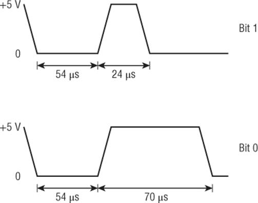
Figure 10.2 DHT11 sending a logical zero and a logical 1
At the end of the communication, the DHT11 pulls the data line back to a logical high.
Hardware
The hardware configuration is fairly straightforward. For this, you need an Arduino Uno. The WiFi shield is socketed on top of the Arduino. The DHT11 will be connected to +5 V and ground, and the data pin will be connected to digital pin 10. There is also a 10-kilohm pull-up resistor on the data line. Digital output 13 will also be used to turn on and off the internal LED for status indication. If the LED is on, then there is a problem with the board. The setup is shown in Figure 10.3.
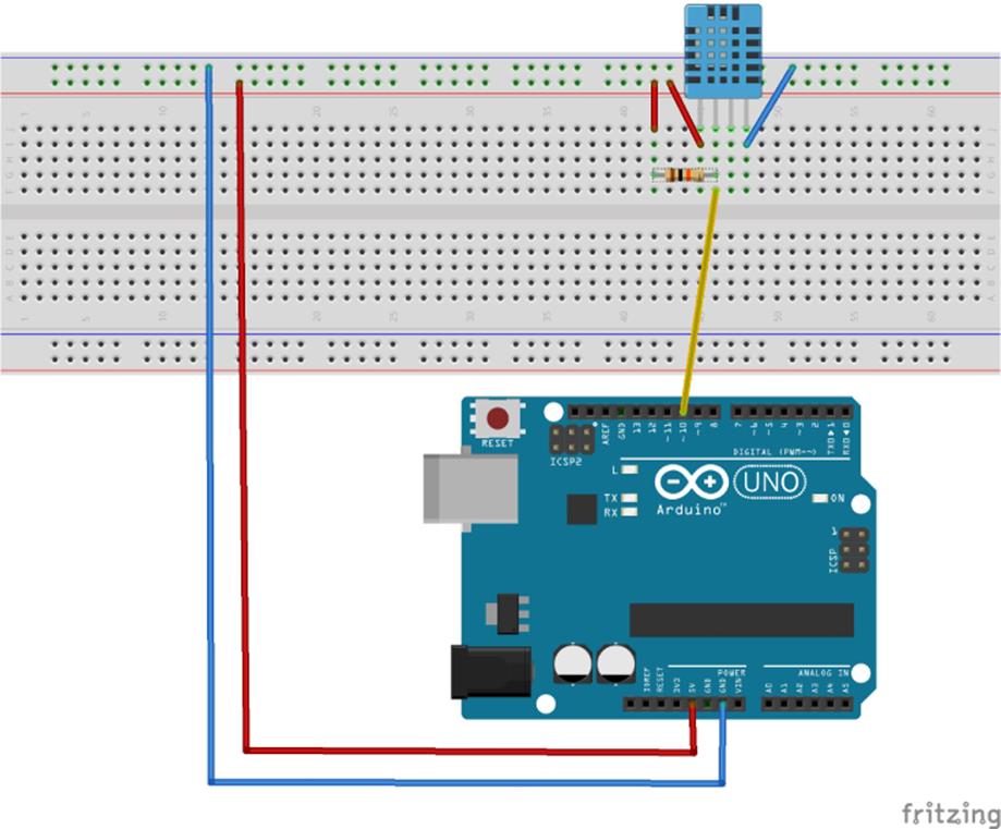
Figure 10.3 Hardware schematic (Image created with Fritzing)
Sketch
Time to get to work! Now that the hardware is complete, it is time to write the sketch. The sketch will look like that shown in Listing 10.1.
Listing 10.1: Wireless Sensor Sketch (filename: Chapter10.ino)
1 #include <WiFi.h>
2 #include <WiFiClient.h>
3
4 const int DHTPin=10;
5 const int LEDPin=13;
6
7 const int MINHumidity=25;
8
9 char ssid[] = "yourNetwork"; // Your network SSID (name)
10 char pass[] = "secretPassword"; // Your network WPA2 password
11 char server[] = "smtp.yourdomain.com"; // Your SMTP server
12
13 boolean firstEmail = true;
14
15 int status = WL_IDLE_STATUS;
16
17 WiFiClient client; // Set up the wireless client
18
19 void setup()
20 {
21 Serial.begin(9600);
22
23
22 Serial.println("Plant monitor");
23
24 // Configure the LED pin, set as output, high
25 pinMode(LEDPin, OUTPUT);
26 digitalWrite(LEDPin, HIGH);
27
28 // Is there a WiFi shield installed?
29 if (WiFi.status() == WL_NO_SHIELD) {
30 Serial.println("ERR: WiFi shield not found");
31 // No point continuing with the sketch
32 while(true);
33 }
34
35 // Attempt to connect to the WiFi network
36 while ( status != WL_CONNECTED) {
37 Serial.print("Attempting to connect to WPA SSID: ");
38 Serial.println(ssid);
39 // Connect to WPA/WPA2 network:
40 status = WiFi.begin(ssid, pass);
41
42 // Wait 10 seconds for connection:
43 delay(10000);
44 }
45
46 // If we got here, then the connection is good. Set LED pin low
47 and display information on serial
48 digitalWrite(LEDPin, LOW);
49 Serial.println("Connected!");
50 }
51
52 void loop()
53 {
54 // Get a humidity reading
55 int val = getDht11Humidity();
56
57 // Print it out to the serial port
58 Serial.print("Current humidity: ");
59 Serial.print(val);
60 Serial.println("");
61 if (val < MinHumidity)
62 {
63 // Below minimum humidity. Warn!
64 Serial.println("Plant is thirsty!");
65 sendEmail();
66 firstEmail = false;
67 }
68 else
69 {
70 // All OK
71 Serial.println("Humidity OK");
72 firstEmail = true;
73 }
74
75 // Wait for half an hour
76 delay(1800000);
77 }
78
79
80 int getDht11Humidity()
81 {
82 byte data[6] = {0};
83
84 // Set up variables
85 byte mask = 128;
86 byte idx = 0;
87
88 // Request a sample from the DHT11
89 pinMode(DHTPin, OUTPUT);
90 digitalWrite(DHTPin, LOW);
91 delay(20);
92 digitalWrite(DHTPin, HIGH);
93 delayMicroseconds(40);
94 pinMode(DHTPin, INPUT);
95
96 // Will we get an ACK?
97 unsigned int loopCnt = 255;
98 while(digitalRead(DHTPin) == LOW)
99 {
100 if (--loopCnt == 0) return NAN;
101 }
102
103 loopCnt = 255;
104 while(digitalRead(DHTPin) == HIGH)
105 {
106 if (--loopCnt == 0) return NAN;
107 }
108
109 // Acknowledged, read in 40 bits
110 for (unsigned int i = 0; i < 40; i++)
111 {
112 // Pin will go low. Wait until it goes high
113 loopCnt = 255;
114 while(digitalRead(DHTPin) == LOW)
115 {
116 if (--loopCnt == 0) return NAN;
117 }
118
119 // What is the current time?
120 unsigned long t = micros();
121
122 // Pin will go high. Calculate how long it is high.
123 loopCnt = 255;
124 while(digitalRead(DHTPin) == HIGH)
125 {
126 if (--loopCnt == 0) return NAN;
127 }
128
129 // Is this a logical one, or a logical zero?
130 if ((micros() - t) > 40) data[idx] |= mask;
131 mask >>= 1;
132 if (mask == 0) // next byte?
133 {
134 mask = 128;
135 idx++;
136 }
137 }
138
139
140 // Get the data, and return it
141 float f = data[0];
142 return (int)f;
143 }
144
145
146 boolean sendEmail()
147 {
148 // Attempt to connect
149 if(!client.connect(server,25))
150 return false;
151
152 // Change this to your IP
153 client.write("helo 1.2.3.4\r\n");
154
155 // change to your email address (sender)
156 client.write("MAIL From: <plant@yourdomain.com>\r\n");
157
158 // change to recipient address
159 client.write("RCPT To: <you@yourdomain.com>\r\n");
160
161 client.write("DATA\r\n");
162
163 // change to recipient address
164 client.write("To: You <you@yourdomain.com>\r\n");
165
166 // change to your address
167 client.write("From: Plant <plant@yourdomain.com>\r\n");
168
169 client.write("Subject: I need water!\r\n");
170
171 if (firstEmail == true) // First email
172 {
173 client.write("I'm thirsty!\r\n");
174 }
175 else
176 {
177 int i = random(4);
178 if (i == 0)
179 client.write("You don't love me any more, do you?\r\n");
180 if (i == 1)
181 client.write("All I know is pain…\r\n");
182 if (i == 2)
183 client.write("I would have watered you by now…\r\n");
184 if (i == 3)
185 client.write("My suffering will soon be over…\r\n");
186 }
187
188 client.write(".\r\n");
189
190 client.write("QUIT\r\n");
191 client.stop();
192
193 return true;
194 }
This sketch has four functions: the setup() and loop() that are present in every sketch and two others, getDht11Humidity() and sendEmail().
At the start, the sketch includes two libraries: WiFi.h and WiFiClient.h. On lines 4 and 5, two pins are defined: the pin connected to the DHT11 data pin and the pin connected to an LED. On line 7, another pin is defined: MINHUMIDITY. This is the value that will be used as a warning level for the sensor; if the humidity falls below this level (expressed as relative humidity), the user will be warned.
On lines 9, 10, and 11, three variables are defined as char arrays. These need to be changed depending on your network setup; they are the SSID the Arduino will connect to, the password to use, and the SMTP server that will be used to send e-mails.
On line 13 is a variable: thirsty. This is a boolean: true if the plant needs water, and false if the dirt has enough humidity. Finally, you have an int named status. This is the status of the wireless connection and will be used later.
setup() is declared on line 19. setup() needs to do several things: configure the serial port for debug messages (line 21), set the LED pin correctly and turn the LED on (line 26), test to see if a WiFi shield is connected (line 30) and attempt to connect to a wireless network (line 37). It loops until the sketch connects to the designated network. When it does, the LED is turned off, and a message is sent to the serial port.
loop() is declared on line 53 and does one simple task. It gets a humidity reading from the DHT11 (on line 56), prints out the data to the serial port (line 59), and then calculates if the sensor reading is less than the minimum humidity level. If it has, then the plant is thirsty, and the user is warned. It sends out a message to the serial connection on line 58 and then calls a function: sendEmail(). Finally, the variable thirsty is set to true. If the minimum humidity level has not been reached, the plant is probably happy as it is, and the thirsty variable is set to false, telling the sketch that all is well. Finally, a delay() tells the Arduino to wait for one-half an hour before taking another reading.
setup() and loop(), required by all Arduino sketches, have been written, but two more are required; one of them reads in data from the DHT11 and reports the humidity level, and the second one sends an e-mail. The first function is getDht11Humidity(). This function is responsible for initiating communications with the DHT11, requesting data, receiving that data, and parsing part of it. It's a complicated function, but don't worry; it isn't that hard.
First off, there needs to be some variables to manipulate and hold data from the sensor, an array named data, and two bytes named mask and idx. To request a sample from the DHT11, the data line must be pulled low for at least 18 milliseconds and then set high. This is done on line 89 by setting the pin as an OUTPUT. It is pulled LOW; then a delay() function waits for 20 ms before setting the pin HIGH again. The sketch waits for 40 microseconds and then switches the DHT pin to INPUT. The DHT11 can now transmit data.
First, the DHT confirms that it has received an order by replying with an ACK. According to the datasheet, when the DHT11 is ordered to send data, it first responds by first driving the data pin low for 80 μS, and then high for 80 μS. It then again pulls the data pin low, ready to send data. This is its way of acknowledging the order, and informing the microcontroller that it will soon send data. The sketch waits until the line is set HIGH, and then it waits again until the line is pulled LOW. This is done on lines 98 and 104. Both portions of the sketch have a time-out; if 255 cycles have passed, the sketch reports a time out. The 255 cycles correspond to more than 80 µs, so if the time out occurs, there was indeed a problem; the ACK wasn't sent.
On line 110, a for loop is created. When the DHT11 has finished acknowledging reception, it will send 40 bits of data. This loop repeats 40 times once for each of the 40 bits the DHT11 should send. First, the pin is set LOW. Remember, the DHT11 sends and receives on a single wire. Previously, the Arduino had control of the wire, but when the signal was sent, it also signaled the DHT11 that it will be responsible for setting the state of the digital pin. To allow it to do this, the pin must be set LOW, and now becomes an input.
The state of the input is read on line 114; as long as the pin is low, this portion of the code repeats (unless a time-out occurs). When the line is set HIGH by the DHT11, this is where the work starts. First, the current system clock time is stored in a variable. This is the amount of microseconds the system has been powered on. A while() loop is created on line 125 and repeats as long as the pin is at a logical one, or HIGH. When the DHT sets the pin LOW, another time reading is made, and the difference between the two is calculated. If the data line was high for 24 µs, it was a logical zero. If the line was high for 70 µs, it was a logical one. The Arduino can't tell exactly when the pulse started and when it stopped, but it can guess closely. The easiest thing to do is to split the values: say, 40 µs. If the pulse were calculated as lasting more than 40 µs, the DHT11 sent a logical one; otherwise, it sent a logical zero. This is done on line 131. Afterward, the value is masked into the data buffer. Each bit is masked on each byte, incrementing the bit until the byte is complete and then moving on to the next byte.
So what is this NAN that is returned if something goes wrong? NAN is short for Not A Number, and is a good way of returning an error message for functions that expect numerical returns. If the function returns something that is not a number, that means there was an error reading one of the return bits.
The DHT11 sends the relative humidity value as a byte, an int is created from the first byte sent to be returned to the main program This int will contain the relative humidity, directly in percent.
Now, all that is left to do is to create a function to write e-mails. The function is declared on line 144. On line 149, the WiFi client attempts to connect to an e-mail server, on port 25. It uses an if statement, but checks for the result of a function, and not a variable. The exclamation mark in front of the function means NOT; it will execute the contents of the if statement if the result of the function is NOT TRUE. If the connection is refused, the function returns false.
Despite what might be thought of the complexity of e-mails, the SMTP protocol is extremely simple. The user must first authenticate, tell the server who he is, who he wants to contact, and then send the data. That's it! Almost… Some servers will require authentication, this will be explained below.
This function has all the lines necessary for communication with an SMTP server. You must specify your own “from e-mail”, the “to e-mail”, and a few other parameters. Remember the firstEmail variable? This is where it is used. If firstEmail is true, the sketch is sending its first email, so a nice e-mail should be sent. This is done on line 173. If the firstEmail variable is false, this isn't the first time an e-mail has been sent to the user, and he probably needs a gentle reminder. On line 177, a random number is generated, and then one of four messages are used. The user was warned, wasn't he? Well, in that case, the plant has the right to insist a little more by sending some different messages.
Finally, the client sends a message informing the SMTP server that it has sent all the data required and then quits. The client.stop() function makes sure that the Arduino disconnects from the SMTP server. The function then returns true, informing the sketch that everything went well.
Exercises
The sendEmail() function sends all the required information to an SMTP server, but SMTP servers also send information, including information that could be useful in case of a disconnection (wrong e-mail, server full, and so on). Have a look at the SMTP documentation, or a few examples of how SMTP servers work, and add some functions to verify the data sent by the server. Many examples are on the Internet, including some examples using Telnet with SMTP, which might be a good place to start. An example of SMTP exchanges is available at http://packetfury.net/index.php/en/Arduino/tutorials/251-smtp.
When placing a WiFi shield on the Uno, the internal LED is probably hidden. Try adding an external LED to the device to show that an error has occurred, and a second external LED to indicate the plant needs water.
While some SMTP servers will not require authentication, there are more and more servers that do. This adds one additional step. A login requires three elements: the user login, the password (of course), but also a step to tell the server what type of authentication you are requesting. The most common authentication is LOGIN. The server will request a simple login and password. To request a LOGIN authentication, you must send a new line:
auth login
The server will respond with a strange line, something like this:
334 VXNlcm5hbWU6
So what is this? This is an encoded word, written in Base64. This is a way of including special characters like accents and non-Latin letters in ASCII. You must first convert your login and password to Base64, using one of the numerous web pages available. You can find a Base64 encoder at http://packetfury.net/index.php/en/Arduino/250-base64.php.
The exchange with the server will look like this:
Client: auth login
Server: 334 VXNlcm5hbWU6
Client: <login>
Server: 334 UGFzc3dvcmQ6
Client: <password>
In your sketch, add some form of authentication, maybe like this:
client.write("auth login");
client.write("<Base64 login>");
client.write("<Base64 password>");
Summary
In this chapter, you have seen how to install and use Arduino's WiFi board, how to scan for wireless networks, and how to connect to a wireless network. I have shown how to read from a sensor using a single wire, and how to connect to an SMTP server to send an e-mail. In the next chapter, you will see more about SD cards: what they are, how they can be used, and how to read and write data to and from these devices using an Arduino.
All materials on the site are licensed Creative Commons Attribution-Sharealike 3.0 Unported CC BY-SA 3.0 & GNU Free Documentation License (GFDL)
If you are the copyright holder of any material contained on our site and intend to remove it, please contact our site administrator for approval.
© 2016-2026 All site design rights belong to S.Y.A.