Arduino Sketches: Tools and Techniques for Programming Wizardry (2015)
Part II. Standard Libraries
Chapter 11. LiquidCrystal
This chapter discusses the following functions of the LiquidCrystal library:
· LiquidCrystal()
· begin()
· print()
· write()
· clear()
· home()
· setCursor()
· cursor()
· noCursor()
· blink()
· noBlink()
· rightToLeft()
· leftToRight()
· scrollDisplayLeft()
· scrollDisplayRight()
· autoscroll()
· noAutoscroll()
· createChar()
The hardware needed to use the examples in this chapter includes:
· Arduino Mega 2560
· SainSmart LCD Shield
· HC-SR04 ultrasonic distance sensor
You can find the code download for this chapter at http://www.wiley.com/go/arduinosketches on the Download Code tab. The code is in the Chapter 11 download folder and is named Chapter 11.ino.
Introduction
For computers to be effective, they require two things: a way to input data and a way to output data. Data output can be in several forms; sometimes, it is invisible, communicating with other devices, such as safety systems in transportation. They are busy keeping you safe, but you will never see them. Other forms are slightly more visible: devices designed to turn on other devices, such as a timer designed to turn on a coffee machine at a particular time. They have the capacity to interact with the outside world but can be difficult to see.
Of all the human senses, sight is probably the most powerful. The best way for a computer to communicate data to the user is visually. Lights are often used for small quantities of data; a small light on your television set can tell you if it is receiving information from a remote control, and the amount of devices that tell you if they are powered with a simple red light is staggering. When more data needs to be displayed, other methods need to be used.
One of the most frequently used methods of displaying data is the liquid crystal display. Liquid crystal displays (or LCDs for short) can be found in digital watches, calculators, agendas, and vending machines, and the same technology is used for computer screens. They get their name from the thin film of liquid crystal contained inside the screen, wedged between two conductive plates. When in their natural state, the crystals inside the liquid are twisted, and light can pass through. When the crystals are subjected to an electrical current, they untwist, blocking the light. This makes the portion of the screen black.
LCD technology is fast and reliable, and uses little energy. Solar powered calculators allowed the user to make calculations with a minimal amount of light, and the solar panel was more than sufficient to power the processor and the LCD screen.
The earliest LCD screens were used to display numbers, typically for pocket calculators or wristwatches. To simplify the design, a format was created, one that allows the display of all numbers from 0 to 9. When decimal points were added, it became the perfect screen for calculators. An example is shown in Figure 11.1.
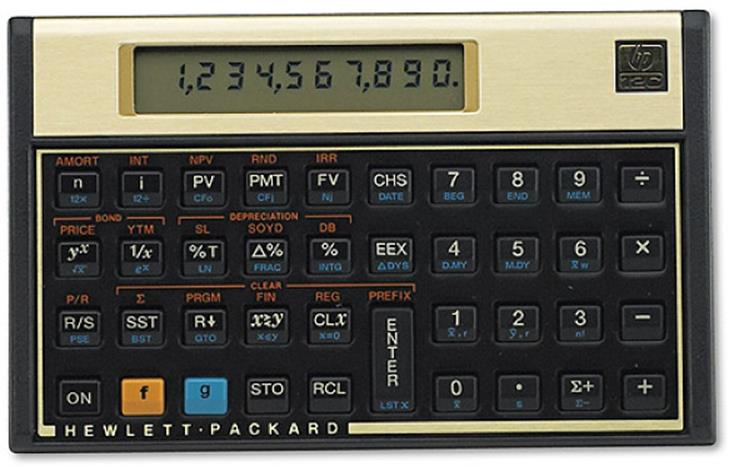
Figure 11.1 LCD screen of a calculator, displaying numbers
Although this works great for numbers, it doesn't work as well for letters. Some letters can be approximated, and some words can be guessed. Hands up; how many of you used calculators to write words? For example, entering 77345993 on a calculator and turning it upside down for EGGSHELL? I did.
To allow letters to be printed, the previous system was modified, adding more segments. This did indeed work, even if it increased the complexity of the LCD screen and the electronics needed to control it. It still wasn't perfect, and some letters were slightly difficult to read: for example, the letter V. Also, it did not allow for uppercase and lowercase letters to coexist; only uppercase letters were displayed and not every lowercase letter could be easily displayed. An example is shown in Figure 11.2.
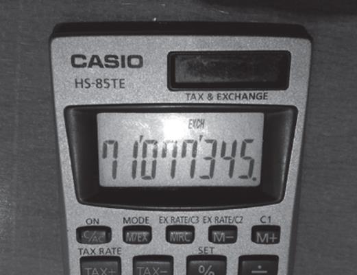
Figure 11.2 LCD screen showing text
Electronics became smaller and smaller, while still becoming more and more powerful. New production techniques allowed LCD screens to become more and more advanced, and a new generation was born.
Modern LCD screens can display numbers and letters: both uppercase and lowercase. Much like the fonts on a computer screen, text and numbers can be written using a matrix of dots. By creating a simple matrix of 5 x 7 points, every single letter in the Latin alphabet can be displayed, and this even works on other alphabets. The downside to this is the complexity of the electronics involved to create connections for a matrix of 5 by 7 squares for every letter required, but most displays come with an integrated controller making the task much easier. Just tell the display what you want to print, and the controller does all the hard work for you.
This type of LCD screen does not talk about resolution. A typical desktop or laptop screen talks about a resolution in pixels, but these screens talk about the number of letters; 16 x 2 means 16 letters on two lines. It does not talk about resolution because this isn't how these screens work; they are composed of several small 5 x 7 screens, but with space between each segment. It isn't possible to display graphics on this type of screen.
LiquidCrystal Library
The Arduino LiquidCrystal library has been designed specifically for one controller: the Hitachi HD44780. Numerous boards exist with this controller, and it is so popular that other controllers also have HD44780 compatibility.
Before using the library, it must first be imported. To import the library, go into the Arduino IDE, and select the menu Sketch ![]() Import Library
Import Library ![]() LiquidCrystal. Alternatively, you can manually add the header file into your sketch:
LiquidCrystal. Alternatively, you can manually add the header file into your sketch:
#include <LiquidCrystal.h>
To use the LiquidCrystal library, you must first create a named LiquidCrystal object. Numerous parameters are required, and values depend on the device that you will be using.
LiquidCrystal lcd(rs, enable, d4, d5, d6, d7);
LiquidCrystal lcd(rs, rw, enable, d4, d5, d6, d7);
LiquidCrystal lcd(rs, enable, d0, d1, d2, d3, d4, d5, d6, d7);
LiquidCrystal lcd(rs, rw, enable, d0, d1, d2, d3, d4, d5, d6, d7);
The rs parameter is short for Register Select and indicates the pin that is connected to the LCD's RS input. The enable parameter allows selection of the LCD device and indicates the pin that is connected to the LCD's ENABLE connector. The r/w parameter is an optional parameter used to indicate if the Arduino is reading from or writing to the LCD screen. Some applications will write only to the LCD screen, in which case the R/W pin can be omitted. Otherwise, it must be connected to the LCD's R/W pin.
The remaining parameters are the data pins. Two options are available: either selecting four data pins or eight. This means that data sent to or received from the LCD controller is either in 4-bit mode or 8-bit. Originally, all data was written in 8 bits, but 4-bit mode allows programmers to send two 4-bit messages to be interpreted as an 8-bit message. This allows the designer to save four digital I/O pins when designing devices.
NOTE
There are several misunderstandings about the difference between 4-bit mode and 8-bit mode. One of them is about speed. It is indeed “faster” to send a single 8-bit message instead of two 4-bit messages, but with more than 90 percent of alphanumeric LCD screens, speed is not an issue. They have a relatively low refresh rate, meaning that it is possible to send an entire 2 x 16 message to the LCD screen before it has time to refresh the screen, even when using 4-bit mode.
When the LiquidCrystal object has been correctly created, it is necessary to initialize it. This is achieved with begin().
lcd.begin(cols, rows);
This function requires two parameters: the amount of columns and rows that the LCD device supports. Typical LCD screens are 2 x 16, but numerous models exist, and it isn't possible to ask every device what size they are. This information must be given.
Writing Text
The main function of an alphanumeric LCD screen is, of course, to display text. Because these screens have a built-in microcontroller, they perform almost exactly like serial terminals. When you send ASCII text to the controller, it prints those characters to the LCD screen. Just like a serial console on your computer, it continues to display those characters until you send more text than can be displayed, or until you send it an instruction.
To write text directly to the LCD screen, use print().
result = lcd.print(data);
result = lcd.print(data, BASE);
The data variable is of any data type; typically this would be a chain of characters, but it can also be numerical data. If it is numerical data, it will be printed as decimal by default, but this can be configured using the optional BASE parameter by selecting one of BIN, DEC,OCT, or HEX. This function returns a byte, the number of bytes written to the LCD device.
To print a single character, use write().
result = lcd.write(data);
The data parameter is a character that will be printed to the LCD. This function returns a byte; the number of bytes written to the LCD device (in this case, either 1 if successful, or 0 if there was an error).
To clear the screen, call clear().
lcd.clear();
This function takes no parameters and does not return any information. It sends a command to the LCD microcontroller to erase any text on the screen and to return the cursor to the top-left corner.
Cursor Commands
Cursor functions work similarly to the cursor on a spreadsheet; you may set the cursor to be at any position, and the text you enter will be printed at that position. By default, the cursor is set at the top-left side of the screen when initializing and will be updated to be placed at the end of any text that you write. When adding text to the display (by using multiple print() calls, for example), it will be added to the end of the line. So, for example:
lcd.print("Hello, ");
lcd.print("world!");
These two lines will result in printing a single line: “Hello, world!” This is useful when calling print() several times if displaying numerical values:
lcd.print("Temperature: ");
lcd.print("temp, DEC");
However, you can return the cursor to the top-left of the screen using home():
lcd.home(); // Returns the cursor to row 0, column 0
You can also place the cursor precisely where you want using the setCursor():
lcd.setCursor(col, row);
By default, the cursor itself is invisible. To make it visible (as an underscore at the position where the next character will be printed), use cursor():
lcd.cursor();
To disable the cursor again, use noCursor():
lcd.noCursor();
These two functions do not take any parameters and do not return any data.
To display a blinking cursor, use blink():
lcd.blink();
To hide the blinking cursor, use noBlink().
lcd.noBlink();
Using cursor() or blink()may produce unexpected results; the exact results depend on the screen's manufacturer. Consult your documentation.
Text Orientation
Text can be oriented both left to right and right to left. By default, LCD alphanumerical displays are configured to be left to right. On startup, the cursor is placed at the far left, and each character makes the cursor move one step to the right. To configure the LCD screen to be in right-to-left configuration, use this function:
lcd.rightToLeft();
This function takes no parameters and returns no data. To change the orientation back to left to right, use the following function:
lcd.leftToRight();
Neither function affects previously written text, and the cursor's position is not updated.
Scrolling
LCD displays are used on numerous devices; they are cheap and reliable. You see them often on cash registers in supermarkets; an LCD device can tell you what item the cashier has just scanned and the cost of the item. At the end, it gives you the grand total to double-check with your calculations. Assuming that you want to print the total and that you need room for two decimal places, a decimal point, a dollar sign, and the remaining room for digits, then a standard 16 x 2 LCD device can be used for some expensive shopping. Sixteen characters are more than enough to display prices but become far too small if you want to place your company name or even some text. “Thanks for shopping with us; have a nice day!” is far too large for a 16 x 2 LCD screen, even on two lines. So how can you print all that? The answer lies with scrolling, pushing existing characters out of the way for new text.
Text can be scrolled in two directions: left and right. The following functions shift both the text and the cursor by one space, either left or right:
lcd.scrollDisplayLeft();
lcd.scrollDisplayRight();
Automatic scrolling enables a simpler approach; text is automatically shifted when a character is printed to the screen. Automatic shifting can be done in both left-to-right or right-to-left configurations and depends on the current position.
To enable autoscroll, call autoscroll():
lcd.autoscroll();
From here on, subsequent writes to the screen will result in previous characters to be automatically shifted. To disable autoscroll, use noAutoscroll():
lcd.noAutoscroll();
Note that the cursor is also autoscrolled; this has the effect of always writing new characters to the same position.
Custom Text
Alphanumeric LCD screens are widely used, and it is not possible to imagine every use case before production. Although most simply display the time or short text, some require more advanced use. Imagine a home wireless telephone; the LCD screen is designed to print simple text, phone numbers, and why not a menu system to configure the telephone, but the constructor also wanted to add some information: the current battery level. It would be possible to display the battery level as a percentage or simply to ignore the battery if it is more than 25 percent charged, but maybe you would like to create your own character, something that resembles a battery. Maybe an elevator in a high rise building has an intelligent system. If you want to go to floor 42, the elevator will tell you to use a particular elevator. For example: Floor 42, →. The arrow will indicate that you should use the elevator on the right. It is more visual than writing text and might even be more economical to use such a solution because a smaller screen can be used. LCD screens already have a large amount of characters prerecorded, but there is still room for eight custom characters.
To create custom characters, an array of binary data must be created. This data is arranged in eight lines of 5-bit binary data, like so:
byte smiley[8] = {
B00000,
B10001,
B00000,
B00100,
B00100,
B00000,
B10001,
B01110,
};
Now, to attribute that data to a character, use createChar():
lcd.createChar(num, data);
The num variable is the number of the character; slots 0 to 7 are available. The data parameter is the data structure you created previously. For example:
lcd.createChar(0, smiley);
Finally, to use the custom character, use write() specifying the byte to use:
lcd.write(byte(num));
Example Program
For this example, you build a distance sensor: a small device that displays the distance of the closest object to the device. Distance sensors are found in daily life; for example, they are used on building sites to know the distance between two walls or by real estate agents to calculate the size of a room. They are also used by robots to detect obstacles and used by cars in exactly the same way to help you reverse into a tight parking space.
There are several ways to achieve this, but they all rely on the same principle: bouncing waves. By emitting a certain frequency, the device calculates the time taken to receive a “copy” of that wave. Imagine yourself in a large open space: a stadium or in the mountains. When you shout, you wait for a small period of time before hearing your echo. Sound has traveled from your mouth and propagates. When it hits a solid surface, it reflects and is dispersed in different directions. Some of that sound returns to you, and your ears hear the sound. By calculating the time it took to hear your echo and factoring in the speed of sound, you can get a rough estimate of the distance. However, this doesn't work for small distances; the speed of sound is so fast that it is impossible for a human to calculate the distances inside a house, but for electronics, it isn't a problem. The HC-SR04 is one device that can do this.
The HC-SR04 is an ultrasonic distance sensor, as illustrated in Figure 11.3. Ultrasonic distance sensors are easily recognizable by their shape. When placed on a robot, it looks like two “eyes,” and in a way, they are. One “eye” is an ultrasonic speaker, and the second is an ultrasonic microphone. Ultrasound waves are created, and the device calculates the time taken for those waves to return to the device. This results in surprisingly accurate results and is good for distances up to four meters away.
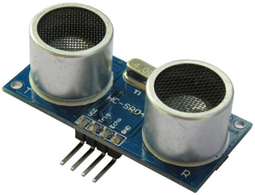
Figure 11.3 HC-SR04 Ultrasonic Sensor
The sensor has four pins: one for the power, one for the ground, one to issue a pulse, and the final pin to read the distance. The result is not in a binary format; this pin will not output text or data in a serial fashion. Instead, the pulse length is proportional to the time taken to receive a result. Fortunately, the Arduino can handle this with a single command.
To allow the user to read the data easily, an LCD screen will be used. This setup could easily be used with a serial device, but that doesn't make sense. The serial port displays text and so does an alphanumeric LCD screen. Only LCD screens are significantly more user-friendly.
This example uses a SainSmart LCD Keypad shield. This shield contains a 16 x 2 LCD screen with a nice blue backlight. It contains all the electronics necessary to use an LCD screen: power, the backlight control, all connected to the Arduino on digital pins. It uses four data pins, and therefore will use 4-bit commands. The example is not specific to this shield, but if you use a different screen, make sure your code and wiring reflects the necessary changes.
Hardware
The SainSmart LCD Keypad shield is a fairly large device. A normal 16 x 2 LCD screen is about as long as an Arduino Uno, and this shield covers the Uno completely, making it difficult to add additional peripherals. For this reason, the Arduino Mega2560 was chosen. It is longer than the Uno, and even with the shield present, there are still a large amount of I/O pins available. The HC-SR04 ultrasonic distance sensor is a small device, and by chance, is exactly as wide as the extended digital outputs of the Arduino Mega2560. To create a self-contained device, the sensor will be placed directly into the header pins, bypassing the need for a breadboard. Let me explain.
By reading the datasheet of the HC-SR04, available at http://packetfury.net/attachments/HCSR04b.pdf, you can find the requirements for powering the sensor: one pin for power and one ground connection. The maximum current used by the sensor is 15 mA. The maximum power delivered by the Arduino's I/O pins can't exceed 40 mA. That is more than double, a comfortable safety margin. The pin connected to the sensor's VCC sets as output and sets HIGH. The pin connected to the sensor's ground also is an output but setsLOW. Just as LED lights can be powered by an I/O pin pulled HIGH, the sensor will be powered by these pins. Similarly, the ground can be an I/O pin pulled LOW. The sensor will be sufficiently powered by the board, but remember that this is a prototype and designed for simplicity. It is possible to do what you are about to do, but if you end up creating your own shield with an LCD screen and ultrasonic distance sensor built in, it is good practice to route the shield so that the sensor is powered by the main power, not powered by the Arduino.
WARNING
Don't connect the sensor just yet! The reason for this is explained later in this chapter when I talk about the sketch.
Software
The sketch is shown in Listing 11.1.
Listing 11.1: Sketch (filename: Chapter 11.ino)
1 #include <LiquidCrystal.h>
2
3 const int vccPin=40;
4 const int gndPin=34;
5 const int trigPin=38;
6 const int echoPin=36;
7
8 // Initialize the library with the numbers of the interface pins
9 LiquidCrystal lcd(8, 9, 4, 5, 6, 7);
10
11 void setup()
12 {
13 Serial.begin (9600);
14
15 // Set up the LCD's number of columns and rows
16 lcd.begin(16, 2);
17
18 // Configure the pins
19 pinMode(trigPin, OUTPUT);
20 pinMode(echoPin, INPUT);
21 pinMode(vccPin, OUTPUT);
22 pinMode(gndPin, OUTPUT);
23
24 // Trigger set to low
25 digitalWrite(trigPin, LOW);
26
27 // VCC and GND
28 digitalWrite(vccPin, HIGH);
29 digitalWrite(gndPin, LOW);
30
31 // Prepare LCD screen text
32 lcd.print("Distance");
33 }
34
35 void loop()
36 {
37 long duration, distance;
38
39 digitalWrite(trigPin, HIGH);
40 delayMicroseconds(10);
41 digitalWrite(trigPin, LOW);
42
43 duration = pulseIn(echoPin, HIGH);
44 distance = duration / 58;
45
46 // Set the cursor to column 0, line 1 (beginning of second line)
47 lcd.setCursor(0, 1);
48
49 if (distance >= 400 || distance <= 0)
50 {
51 // Inform the user that we are out of range
52 lcd.print("Out of range");
53 }
54 else
55 {
56 // Tell the user what distance has been detected
57 lcd.print(distance);
58 lcd.print(" cm "); // Extra space overwrites any text
59 }
60
61 // Wait for half a second before repeating
62 delay(500);
63 }
From the start, on line 1, the LCD library is imported. Afterward, four pins are defined as constants: vccPin, gndPin, trigPin, and echoPin. These pins correspond to the pins found on the HC-SR04 sensor board. The vccPin and the gndPin are the power pins, and trigPinand echoPin are the data pins. Later, trigPin will be an output, and echoPin will be an input.
On line 9, the LCD display is configured, creating an lcd device. This function uses six parameters, which tell the sketch that it will use four data lines and does not use the optional read/write parameter. It is called using six integers: 8, 9, 4, 5, 6, and 7. The first value corresponds to the RS pin. On the SainSmart LCD Keypad shield, RS is pin 8. The second value is the enable pin, and this is wired to pin 9. Finally, 4, 5, 6, and 7 are the data pins. As with the rs and enable pins, these are hardwired on the shield.
On line 11, setup()is declared. On line 13, the serial port is initialized. It isn't used in this example, but it is ready in case you need to start debugging your application. The LCD device is already activated, but the sketch knows only what pins the LCD device is connected to. It still doesn't know how many lines and columns the device has. This is done on line 16 with begin(); it has 16 columns and two lines. On lines 19 to 24, the four pins for the sensor are configured. One pin, echoPin, will be configured as INPUT, and the three others will be OUTPUT. On line 25, the trigger pin is set LOW. On line 28, the vccPin is set HIGH; it will now supply 5 V. On line 29, the gndPin is set LOW; it is now a ground connection. Finally, on line 32, some text is sent to the LCD device: one word—“Distance.” This is printed at the default cursor position: (0,0), located at the top-left corner of the screen. This text will be present at all times, and the text on the second line will be updated in loop().
On line 35, loop() is declared. This is where all the sensor reading and text writing takes place. It starts by declaring two variables: duration and distance. The HC-SR04 requires a pulse on the trigPin pin of at least 10 microseconds. To do this, the sketch first setstrigPin HIGH, waits for 10 microseconds using delayMicroseconds(), and then sets trigPin to a logical LOW.
After receiving a pulse, the HC-SR04 starts working. It emits a number of ultrasonic bursts and listens to the results. After the distance has been calculated, the result is returned via the pulsePin, a variable length pulse. So how can the Arduino know how long the pulse is? The answer is simple: pulseIn(). This function was presented in Chapter 4. Put simply, it waits for a pulse to appear on the designated pin. It waits for the logic level to change and then starts counting. When the logic level changes back to its original setting, it stops counting and returns the length of the pulse in microseconds. This is done on line 53, placing the result into a variable: duration. On line 54, a small calculation is made; the variable duration is divided by 58. This value comes from the sensor's documentation. Divide the number by 58 to get a result in centimeters and by 148 to get the result in inches. Now that you have the distance, it is time to print the results.
The results will be printed on the second line of the LCD screen, so the coordinates must be set. This is done on line 47; the position is set to column 0, line 1. Remember, most numbers start with 0, so this is actually on the first column on the second line. The HC-SR04 can give results up to 4 meters away; values greater than that will be ignored. A quick check is done on line 49 with an if() statement. If the result is greater than 400 centimeters or if the result is negative, the sketch writes “Out of range” if the distance value is out of range. If it is not out of range, the value is printed. This is done in two steps: first, the decimal value is displayed. Afterward, some text is displayed with a leading space and several spaces after the text. Why? Because if the previous text were “Out of range,” the end of that text would still be visible. Writing text on a line does not automatically delete all the text at the end of the line. Just like using the insert function in a word processor, each keypress deletes one character and inserts the character you want in that text, but it does not delete text afterward. To make sure that no trailing text is displayed, several spaces are included.
The last thing that happens is waiting for one-half a second before repeating the process. This is done on line 62. Figure 11.4 shows the finished product.
NOTE
It is vitally important to double-check the Arduino before connecting components. It is tempting to connect the sensor before uploading the sketch to the Arduino, but what would happen if the previous sketch used the I/O pins for something else? In the worst case, the VCC and GND pins could be inverted, essentially reversing the polarity of the component, damaging or destroying it. I have a dozen Arduino boards at home, and it is impossible to remember exactly which board has which sketch. Remember to upload the proper code of your Arduino before connecting external devices.
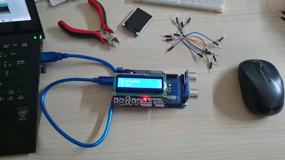
Figure 11.4 The finished product
Exercises
This sketch gives surprisingly accurate results with inexpensive hardware, but a few quick tricks might make this sketch even better. It is currently written for the metric system, using centimeters. You could change the output to meters when the distance value is more than 100. For people using the imperial system, the sketch can be modified to print the data in inches, not in centimeters.
One good way of changing between inches and centimeters would be to use something that the SainSmart LCD Keypad shield already has: a keypad. Look at the documentation; the keypad is an analog device connected to pin A0. When the keypad is pressed, the voltage on A0 changes, and that is how the sketch knows that a button has been pressed. Try to create something that would change the output when one of the buttons is pressed. analogRead() would be useful here for reading the results of keypresses.
Summary
In this chapter, you have seen not only how to connect liquid crystal displays, but you have learned how to create special characters for your device, and how to display data onto the screen. In the next chapter, I will show you the SD library, how it talks to SD cards, and how it can be used to read and write data to a card. You will see a data logging application that will allow you to write thousands of samples to a card, and how to read them back.
All materials on the site are licensed Creative Commons Attribution-Sharealike 3.0 Unported CC BY-SA 3.0 & GNU Free Documentation License (GFDL)
If you are the copyright holder of any material contained on our site and intend to remove it, please contact our site administrator for approval.
© 2016-2026 All site design rights belong to S.Y.A.