Arduino Sketches: Tools and Techniques for Programming Wizardry (2015)
Part III. Device-Specifi c Libraries
Chapter 19. Scheduler
This chapter discusses the following functions of the Scheduler library for the Arduino Due:
· startLoop()
· yield()
The hardware needed to use these functions includes:
· Arduino Due
· LM35 temperature sensor
· PowerSwitch Tail II (110 V or 220 V)
· Adafruit's RGB LED Weatherproof flexi-strip (http://www.adafruit.com/products/346)
· 3 x TIP120 transistors
· 3 x 100-Ω ¼-W resistors
NOTE
The Scheduler library is only found in Arduino IDE version 1.5 and later. It is still considered experimental and under development.
You can find the code downloads for this chapter at http://www.wiley.com/go/arduinosketches on the Download Code tab. The code is in the Chapter 19 folder and the filename is Chapter19.ino.
Introducing Scheduling
Back in the early days of computing, computers could do only one thing at a time. When you turned on your trusty PC and put in a disk, the operating system started. Then you changed the disk and ran a spreadsheet. Your spreadsheet appeared on the screen after a few seconds and you heard some dubious sounds from the disk drive, and then, finally, you could get to work. If you wanted to take a break and play a game in glorious four colors, you had to save your work and quit the spreadsheet (or in some cases, actually restart the computer) before playing a game. With disks, this didn't matter so much; you couldn't have two programs open at the same time.
When graphical systems arrived on the PC, users wanted to have windows containing their applications, but they also wanted to switch from one application to another, or even have two running at the same time. Hard drives could store several programs, and there was enough system memory to have multiple executables in memory at the same time. The question was, how do you run two programs at the same time?
Computer manufacturers started selling computers with graphical systems with a lot of memory and internal hard drives, and this became standard. The more they added on, the more users wanted. To attract users, they would say that you could run several programs at the same time and that they could run simultaneously. This is one of the biggest lies in computers, but it is close enough.
A processor cannot execute multiple programs at the same time; technically it isn't possible. A processor can execute the instructions it is given, one at a time, but the trick is in giving it the instructions it needs to run.
The operating system is the software heart of any system. An application cannot run without the help of an operating system. Even if you use only one program, you can't just install that program onto a computer without an operating system. The operating system does much more than just run programs; it sets up the hardware, including keyboard and mouse inputs, and video output, and it configures the memory as required—something a normal program doesn't need. A program can tell the operating system to print something on the screen, and it is the operating system that does all the hard work, including multitasking.
Multitasking is the art of running several programs in a way that makes users think that they are running at exactly the same time, but they aren't. The operating system gives control to an application (or thread) before either taking back control or waiting until the application gives control back to the operating system, as shown in Figure 19.1.
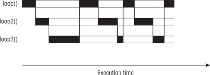
Figure 19.1 Execution of threads
This has led to some complicated situations; Microsoft Windows 3.1 used something called cooperative multitasking, where applications had to cooperate. If an application didn't cooperate (either it wasn't designed to run in Windows or crashed) then control was never given to other applications. In Figure 19.2, the thread badloop() takes control but never gives it back, leaving two threads unable to function.
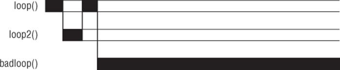
Figure 19.2 Noncooperative thread
Today, operating systems use multiple techniques to ensure that applications will run together, even if one is greedy with system resources, and the entire system keeps on going even if an application crashes.
While writing this book, I am using a text editor. In the background is a music player to help me concentrate. I am using a two-monitor setup, and on the opposite screen I have a web browser for reference, and the Arduino IDE to write the sketches that I will be using. If I need a break, I'll play a game, but I won't close any applications, I'll let the operating system keep them alive while I have a break. When I've had a break, I'll come back to my text editor and continue where I was.
Arduino Multitasking
Arduinos, by default, do not multitask. Take this simple sketch as an example:
// the setup function runs once when you press reset or power the board
void setup() {
// initialize digital pin 13 as an output.
pinMode(13, OUTPUT);
}
// the loop function runs over and over again forever
void loop() {
digitalWrite(13, HIGH); // turn the LED on (HIGH is the voltage level)
delay(1000); // wait for a second
digitalWrite(13, LOW); // turn the LED off by making the voltage LOW
delay(1000); // wait for a second
}
This is the Blink example found in the Arduino IDE's Examples menu. In this simple example, an LED is set to blink: one second on, one second off. The code used to switch between the different states runs quickly; it requires mere microseconds. digitalWrite()requires a little bit more time, but it is still fast. Next, the sketch runs a delay(). This function is called a blocking function; it prevents all other functions from running until it has completed. Because Arduinos are designed to be single-task devices, no multitasking library was originally created. An Arduino will continue to run a single task, waiting for data, or acting on data. Some libraries allow something called a callback; a function that will be run when an external event occurs. For example, an Arduino can't be told to wait forever for an I2C instruction. In this case, a callback is programmed. The Arduino can continue to do what it needs to do (for example, read sensors) and when an I2C instruction arrives, the Arduino stops what it is doing and runs the callback before returning to whatever it was doing before being interrupted. However, this is not the case of most applications; almost all functions are blocking, and other functions cannot run until it has completed.
The Arduino Due uses a different microcontroller; instead of using an Atmel AVR, it uses an Atmel ATSAM3X8, Atmel's implementation of an ARM Cortex-M3 microcontroller. It is a 32-bit device running at 84 MHz. It has some advanced features and is a powerful device. Because of its capabilities, one developer in particular decided to change the way it worked and to implement a scheduling system. The library, called Scheduler, was introduced in Arduino IDE 1.5.
Scheduler
The scheduler implementation is a cooperative scheduler. It remains powerful yet lightweight but does require some careful thinking when implementing. It can run several functions at the same time, so long as they cooperate. It also rewrites one function in particular; the delay() function, which is discussed later in the Cooperative Multitasking section.
The first thing you need to do is to import the Scheduler library. This can be done either from the IDE menu (Sketch ![]() Import Library
Import Library ![]() Schedule) or by adding the include manually.
Schedule) or by adding the include manually.
#include <Scheduler.h>
From here, use startLoop():
Scheduler.startLoop(loopName);
This function takes a single parameter: the name of a function declared inside the sketch. The named function cannot take any arguments, but it can be any function that you wish. Multiple functions can run consecutively by calling startLoop() for each named function:
Scheduler.startLoop(loop1);
Scheduler.startLoop(loop2);
Scheduler.startLoop(loop3);
There is one other function to know about—yield():
yield();
This function takes no parameters, returns no data, and from a visual standpoint, does not do anything, but this is the function that is called to yield control to another function. Remember, the Scheduler library uses cooperative multitasking, so control must be given back to other functions; otherwise, they will not have any CPU time.
Cooperative Multitasking
Consider the following example:
#include <Scheduler.h>
void setup()
{
Serial.begin(9600);
// Add "loop1" and "loop2" to scheduling.
Scheduler.startLoop(loop1);
Scheduler.startLoop(loop2);
}
void loop()
{
delay(1000);
}
void loop1()
{
Serial.println("loop1()");
delay(1000);
}
void loop2()
{
Serial.println("loop2()");
delay(1000);
}
This sketch is simple; it will import the Scheduler library and run two functions: loop1() and loop2(). Remember, loop() is always called. The two additional loop functions will simply print a line of text to the serial port and then wait for a second.
Remember when I said that delay() was blocking? With the Scheduler library, it isn't; it allows functions to sleep for a set time but gives control back to other functions. In this case, one loop is called, and when it reaches delay(), it gives control to the other loop function. When that one reaches delay(), it will once again return control to the first function, and this will happen until delay() ends, after 1 second.
The output of the function on the serial port is a list, alternating between "loop1()" and "loop2()".
Scheduled functions can also use global variables. Change the sketch to add the following:
#include <Scheduler.h>
int i;
void setup()
{
Serial.begin(9600);
// Add "loop1" and "loop2" to scheduling.
Scheduler.startLoop(loop1);
Scheduler.startLoop(loop2);
i = 0;
}
void loop()
{
delay(1000);
}
void loop1()
{
i++;
Serial.print("loop1(): ");
Serial.println(i, DEC);
delay(1000);
}
void loop2()
{
i++;
Serial.print("loop2()");
Serial.println(i, DEC);
delay(1000);
}
A global variable has been added: i. Each time a loop function is called, i is incremented, and the value is displayed. The output of this function is again a list, alternating between "loop1()" and "loop2()" with the variable i incrementing each time.
Noncooperative Functions
Now, add something else. The variable i is incremented each time a loop is called, and we would like to have a message displayed when i reaches the value 20. This can be achieved by adding a third function, one that looks at the value of i and prints a message if the value is reached.
#include <Scheduler.h>
int i;
void setup()
{
Serial.begin(9600);
// Add "loop1" "loop2" and "loop3" to scheduling.
Scheduler.startLoop(loop1);
Scheduler.startLoop(loop2);
Scheduler.startLoop(loop3);
i = 0;
}
void loop()
{
delay(1000);
}
void loop1()
{
i++;
Serial.print("loop1(): ");
Serial.println(i, DEC);
delay(1000);
}
void loop2()
{
i++;
Serial.print("loop2()");
Serial.println(i, DEC);
delay(1000);
}
void loop3()
{
if (i == 20)
{
Serial.println("Yay! We have reached 20! Time to celebrate!");
}
}
The new function, loop3(), is called in the setup() function and has a single task; to monitor the value of i and print a message when i reaches the value 20. Except it doesn't. If you run the program and open a serial monitor, you'll see there is no output from this sketch, and nothing is displayed on the serial port. loop1() and loop2() do not print any values, and loop3() does not celebrate the arrival of the value 20. What happened?
The code is valid; there is no syntax error. Because the code ceased to work when loop3() was added, it is safe to say that the problem lies within this function. Time to take a closer look.
It starts with an if statement: if i equals 20, then a message is printed. And if i doesn't equal 20? Nothing, it just loops. It should work, and on most multitasking systems, it would. Most multitasking systems have a kernel that gives control to functions and then takes control away after a set period of time, or number of instructions, or whatever algorithm the system uses. On cooperative multitasking, it is up to the programs (or functions) to play nice with the other functions and to give control back. The problem withloop3() is that it continues to run but never gives control back to the other functions. It keeps on looping waiting for i to reach 20, when i can never be incremented. The other two functions are still waiting for their turn. To tell loop3() to give control back to other functions, use yield().
void loop3()
{
if (i == 20)
{
Serial.println("Yay! We have reached 20! Time to celebrate!");
}
yield();
}
A single modification has been made; yield() has been added after the if loop. When the sketch reaches this point, it releases control of loop3() and looks to see if any other function needs CPU time. Now all the functions are cooperative, and the sketch functions as needed.
Cooperative multitasking is an excellent way of making reliable multitasking code, without the need for a heavy operating system. However, care must be taken to make sure that the threads are cooperative, by adding yield() functions or delay() statements.
Example Program
This example will be an aquarium temperature sensor, one that will monitor the temperature and control a lighting system and control the temperature depending on the result. Every few seconds, the sensor will send the temperature by serial.
Aquariums can be expensive, and enthusiasts often welcome devices that can help them monitor certain aspects of the water; temperature, acidity, water hardness, and oxygen levels are all critical to the well-being of the fish they contain. A mistake can often be disastrous.
The temperature sensor is simple; as with the previous chapter, you will be using an LM35 temperature sensor. Tropical fish require precise temperatures, and this application can help you achieve that. Most heating elements auto-regulate themselves, but for exotic fish, or for breeding conditions, you may want to regulate the temperature; it should be warmer in the day and slightly cooler at night. Bala sharks, also known as silver sharks, are a beautiful addition to large aquariums—and my personal favorite. They are peaceful creatures but are difficult to please, requiring a temperature between 22 and 28°C. For this application, the heater will be turned off at 26 and turned on at 24.
Also, lighting conditions are important, especially when breeding. Most lighting turns on rather violently in the morning and turns off entirely at night, instead of a more natural cycle of slowly brightening the light and slowly dimming. This sketch enables you to change that. Figure 19.3 shows the lighting strategy.
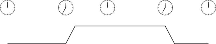
Figure 19.3 Lighting control
The light regulator will use the Arduino Due's digital to analog converter. It will be a single task; one that will wait for hours before changing the light settings.
There are two ways to make a sketch wait for a long time, either using the delay() function, which normally means that no other calculation can take place, or by reading the number of milliseconds since the sketch started. To make things simple, this application will use two loops; one for the temperature sensor and one for the lighting application. Both will be running independently.
Hardware
The Arduino Due will have an LM35 temperature sensor connected to A0. The LM35 will be powered by 5 volts. Even though the LM35 runs at 5 V, it will never reach 3.3 V, so it's safe to connect to the Arduino Due.
WARNING
The LM35 is not waterproof! Do not place it directly in water; it could damage the component and cause oxidation of power wires, resulting in toxic water for the fish. Make sure to totally isolate the LM35 and any wires before placing them inside an aquarium. The outside glass of an aquarium is often a good indication of the temperature of the water; you can place the LM35 outside the tank, directly on the glass.
The PowerSwitch Tail II is a power cable with on-board electronics. When it receives a signal on the input pins, it lets the AC electricity through. It requires little energy to activate; at 5 V, it will draw about 10 mA, which the Arduino is more than capable of delivering. The PowerSwitch Tail II is also “opto-isolated,” meaning that the low voltage is never in any contact whatsoever with the AC lines, making this device extremely safe to use. The output will be connected to digital pin 7.
To light the aquarium, you can use either an LED array or LED strip. Both of these can be found on sites like Adafruit. For this application, I recommend Adafruit's RGB LED Weatherproof flexi-strip (available at http://www.adafruit.com/products/346). These strips contain 60 RGB LEDs per meter, and their length can be adjusted according to your aquarium. However, they draw far more current than an Arduino can deliver, so they require an external power supply and will require three transistors to power them, one for each color channel. A transistor is like a switch: by providing a small current to the base, a much larger current can flow from the collector to the emitter, allowing the Arduino to power devices that either require far more current than what it can provide, or even power devices that require more voltage.
CROSS-REFERENCE
Transistors were presented in Chapter 3 in the “Transistors” section.
To control the light intensity, you will be using PWM. The LED will essentially be turned on and off very quickly, far too fast for the human eye to see, and by varying the duty cycle—that is to say, the amount of time spent on compared to the amount of time spent off—you can adjust the light intensity. The three transistors will be controlled by pins 2, 3, and 4. The TIP120 transistor is a powerful component that can let through a large amount of current compared to what the Arduino can provide, or sink. Adafruit's flexi-strip has four connectors: one for a 12-V power supply, and one for each of the red, green, and blue components. By connecting these to the ground, or 0 V, they turn on each of the color components. This is what the transistor will be used for; it will allow as much current through as is required, but since the base will be connected to PWM, it will turn on and off very quickly, giving the appearance of dimming.
This device does not have a screen and does not provide any way to let the user configure the timing sequence or when it should start. By default, the sketch will begin its timing sequence as if the user had connected it at midday. Figure 19.4 shows the schematic.
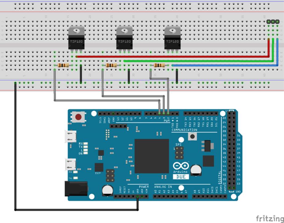
Figure 19.4 Schematic (Image created with Fritzing)
Sketch
Use the code in Listing 19.1 for this sketch.
Listing 19.1: Sketch (filename: Chapter19.ino)
1 #include <Scheduler.h>
2
3 const int sensorPin = A0; // The analog input pin
4 const int powerPin = 7; // The power socket output pin
5
6 const int rPin = 4; // Red color component
7 const int gPin = 3; // Green color component
8 const int bPin = 2; // Blue color component
9
10 const int maxTemp = 26; // Turn off heater when above this temp
11 const int minTemp = 24; // Turn on heater when below this temp
12
13 int powerPinStatus = LOW; // By default, no power on the AC circuit
14
15 int i; // Temporary variable for if statements
16
17 void setup()
18 {
19 // Serial output at 9600 baud
20 Serial.begin(9600);
21
22 // Configure sensor pin
23 pinMode(sensorPin, INPUT);
24
25 // Start heater and lighting treads
26 Scheduler.startLoop(heatloop);
27 Scheduler.startLoop(lightloop);
28 }
29
30 void loop()
31 {
32 yield(); // Releases the Arduino from the main loop
33 }
34
35 // The loop responsible for checking water temperature
36 void heatloop()
37 {
38 // Get a temperature reading from the temperature sensor
39 // 3.3V on the due
40 int tempC = ( 3.3 * analogRead(sensorPin) * 100.0) / 1024.0;
41
42 // Send the temperature reading out the serial port
43 Serial.print("Temperature: ");
44 Serial.println(tempC);
45
46 // Check to see if we need to change the output
47 if (powerPinStatus == LOW)
48 {
49 //Mains plug currently turned off
50 if (tempC < minTemp)
51 {
52 powerPinStatus = HIGH;
53 digitalWrite(powerPin, powerPinStatus);
54 }
55 }
56 else
57 {
58 // Mains plug currently turned on
59 if (tempC > maxTemp)
60 {
61 powerPinStatus = LOW;
62 digitalWrite(powerPin, powerPinStatus);
63 }
64 }
65
66 // Warn if possible heating element failure
67 if (tempC < (minTemp - 2))
68 {
69 Serial.print("CRITICAL: Water temperature too low. ");
70 Serial.println("Heating element failure?");
71 }
72
73 // Sleep for ten seconds
74 delay(10000);
75 }
76
77 // The loop responsible for lighting
78 void lightloop()
79 {
80 // Wait for 7 hours before turning the lights off
81 delay(7 * 60* 60 * 1000);
82
83 // Lower the light level over the span of one hour
84 for (i = 255; i >= 0; i--)
85 {
86 analogWrite(rPin, i); // Write the red light level
87 analogWrite(gPin, i); // Write the green light level
88 analogWrite(bPin, i); // Write the blue light level
89 delay(60 * 60 * 1000 / 255); //Sleep for a few seconds
90 }
91
92 // Wait for 11 hours
93 delay(11 * 60* 60 * 1000);
94
95 // Increase the light level over the span of one hour
96 for (i = 0; i <= 255; i++)
97 {
98 analogWrite(rPin, i); // Write the red light level
99 analogWrite(gPin, i); // Write the green light level
100 analogWrite(bPin, i); // Write the blue light level
101 delay(60 * 60 * 1000 / 255); //Sleep for a few seconds
102 }
103
104 //Wait for 4 hours
105 delay(4 * 60* 60 * 1000);
106 }
This sketch begins by importing the Scheduler library. On lines 3 and 4, the input and output pins are defined. On lines 6, 7, and 8, the pins used to control the color components are declared. On lines 10 and 11, two temperatures are defined; the minimum and maximum temperature. When the minimum temperature is reached, the heating element is turned on. When the maximum temperature is reached, the heating element is turned off. Change the values to suit your aquarium.
On line 13 a variable is declared, containing the status of the output pin. By default, the status is set to LOW. On line 15 a temporary value is declared. It will be used later by one of the functions.
setup() is declared on line 17. It configures the serial port at 9600 baud; it sets the sensor pin to input; and it registers two functions as threads: heatloop() and lightloop().
loop() is declared on line 30 and contains a single instruction: yield(). Every time the CPU gives control to this function, it immediately gives control back to the sketch, allowing the CPU to control the two other scheduled loops.
On line 36, heatloop() is declared. This is the function that supervises the heating element; taking measurements from the LM35 and acting upon that information. First, on line 40, it reads the temperature on the analog input in degrees Celsius. On lines 43 and 44, this temperature is printed to the serial port. On line 47, program execution enters an if statement depending on the state of the output pin. If the pin is set to LOW, it compares the current temperature to the minimum temperature. If the current temperature is too low, the pin status is inverted, and the pin is set to HIGH. If the pin is already HIGH, the current temperature is checked against the maximum temperature. If the temperature is too high, the pin status is again inverted, the pin is set LOW, and program execution continues. On line 7, another comparison is made. If the current temperature is lower than the minimum allowed temperature minus 2 degrees, the serial port issues a warning; maybe the heating element is defective and can no longer heat the water, in which case immediate action should be taken. Finally, the function sleeps for 10 seconds before continuing. Because the Scheduler library has been imported, this is no longer a blocking function; instead, control is given to other threads.
On line 76, lightloop() is declared. This function relies heavily on delay(), something that can be tricky when using threads. It has five phases. First, it runs delay() for 7 hours. Remember, this application will be plugged in at midday, and the lights will begin to dim at 7 P.M. At 7 P.M, the second phase begins; the Arduino's PWM has 256 possible values. A loop, decreases the value of each of the color outputs by 1, creating a delay() over 1 hour divided into 256 steps. Once this hour has passed, the sketch will wait for 11 hours. At 7 A.M, the sketch will begin to increase the light levels using the looping technique, simulating a morning sunrise over the course of an hour. The sketch then waits for another 4 hours, until midday. It then repeats the cycle.
Exercises
This application is extremely useful for fish-keepers, but connecting to the PC to get temperature information may be an unnecessary process. Also, the temperature warning function is critical, but again, if the computer is not turned on, the user never receives his warning. This application could benefit from an LCD screen to be effective—to show the temperature, output status, and any warning messages.
Turning this application on at exactly midday may not be practical for many people. A real-time clock module would be a good tool for keeping accurate timing.
The strip light contains RGB LEDs, and this sketch changes all the colors at the same rate, resulting in white light. However, in some cases you might not want white light, but maybe something more green to simulate a more realistic environment, or maybe leave some blue light on during the night. You can easily change the sketch to add the color you want.
Summary
In this chapter, you have seen how powerful the Scheduler can be with only a few instructions. You have seen how an Arduino Due can perform multiple tasks at the same time, and how to avoid possible problems. In the next chapter, you will see the USBHost library and how to connect USB input devices to your Arduino, allowing text and mouse inputs for your sketches.
All materials on the site are licensed Creative Commons Attribution-Sharealike 3.0 Unported CC BY-SA 3.0 & GNU Free Documentation License (GFDL)
If you are the copyright holder of any material contained on our site and intend to remove it, please contact our site administrator for approval.
© 2016-2026 All site design rights belong to S.Y.A.