Arduino Sketches: Tools and Techniques for Programming Wizardry (2015)
Part III. Device-Specifi c Libraries
Chapter 20. USBHost
This chapter discusses the following functions:
· keyPressed()
· keyReleased()
· getModifiers()
· getKey()
· getOemKey()
· mouseMoved()
· mouseDragged()
· mousePressed()
· mouseReleased()
· getXChange()
· getYChange()
· getButton()
The hardware needed to use these functions includes:
· Arduino Due
· USB keyboard
· USB OTG micro adapter
You can find the code download for this chapter at http://www.wiley.com/go/arduinosketches on the Download Code tab. The code is in the Chapter 20 folder and the filename is Chapter 20.ino.
Introducing USBHost
Most people do not understand the nightmares that some computer users previously had when adding peripherals. When the PC originally shipped, it did not have a mouse as standard; you needed to buy that separately. It came with a keyboard, but that is about it. The keyboard was a standard element to computers, and it still is. Since there is no need to have two keyboards connected to a computer, each PC came with a single keyboard connector, the DIN keyboard connector. It was large and bulky, and kept the connector firmly in place. Then manufacturers decided to add a mouse. Mice were normally sold with a serial connector, the highly reliable RS-232 connector. Because most computers were sold with two serial ports and one parallel port, that was easy. It left ports free.
Suppose the user wanted to add a printer. Printers were almost always connected to parallel ports, but the computer had only one. Then a 56-k modem connected to the remaining serial port. That's it. No more connectors left. This would be a problem if the user wanted to go further and connect a scanner or other device. Expansion cards existed to add a second parallel port, but what if the user wanted a scanner and two printers? Color printers existed, but they were expensive, and the cartridges were even more so. For printing in black and white, some users still preferred to have a second printer for black and white only.
Peripherals were becoming more and more common, and if the user scanned lots of text and images, sooner or later, they would require storage. Iomega's Zip drive was originally an external diskette drive, but one that had a large capacity compared to floppy disks; the original Zip drive could store 100 megabytes. Don't laugh; that was a lot of storage in 1994! The problem was that it was a parallel device requiring a parallel port.
Peripheral shopping became a nightmare. When deciding on buying a peripheral or not, people had to ask themselves, “Do I have a spare serial/parallel/SCSI port?” Mice were serial devices, and because every computer being shipped suddenly had graphical interfaces, a mouse was a requirement. Enter the PS/2 interface.
The PS/2 interface was designed for simplicity. Each computer had one keyboard and one mouse. The old DIN keyboard connector was replaced with a PS/2 keyboard connector, and mice were created with a PS/2 connector. There were two connectors on computer mainboards: one purple port for keyboards and one green port for mice. Both were physically identical: They were mini-DIN connectors. They had the same power connectors and the same data connectors, but if the user mistakenly inverted the keyboard and mouse, they would not function. Simply unplugging and replugging into the correct port resolved this. This left a serial connector free for other peripherals: modems, PC-to-PC connectors, software dongles, joysticks, circuit programmers, parallel port switchers, to name but a few—still far too many. Also, another interesting event was occurring; some users wanted something that the designers hadn't anticipated: two interface options, like one standard mouse for day-to-day operations and either a track-pad or a mouse specialized for graphical work.
To simplify everything, Universal Serial Bus (USB) was created, which is a way of connecting devices to a computer using a standard interface. Keyboards, mice, scanners, modems … just about anything could be connected to the computer using USB. Even better, if the amount of USB ports on the computer weren't enough to add another peripheral, a USB hub could be used. A single USB controller can have as many as 127 different ports by using hubs.
USB Protocol
For USB to work, it requires at least one USB host. This is the device that controls USB devices, and USB devices communicate with the host. For a standard PC setup, the PC is the USB host.
Devices connect to the host, and when they do, an enumeration occurs. Each device connected is given a number from 1 to 127. When enumerated, the device description is read, so the USB host knows what this device can do. Sometimes drivers are needed to fully use a USB device; some devices do not require drivers because the computer already knows what the device's function is. Several USB classes exist, and one of them is called HID, short for Human Interface Device. HID devices include keyboards and mice.
USB devices are “hot pluggable”; they can be connected while the system is running. They can also be disconnected without the need for rebooting; when unplugging your keyboard and plugging it into another USB port takes only a few seconds for the computer to recognize the new port.
For desktop and laptop computers, the USB mechanism is simple; the computer acts as the USB host, and a connected peripheral is a USB device. The computer enumerates the USB device, and a connection is established. For some devices, like mobile phones, this is a more complicated process.
Mobile phones lack the connectivity possibilities of a computer. They have a single USB port, no disk drive, no CD drive, and limited capabilities for physical input. Some phones can be used as USB drives; plug in the right kind of smartphone to a computer, and the telephone can use an internal SD card as a disk, allowing the computer access to the files. This is great when you want to copy multimedia files onto a telephone, but it isn't always practical. What happens when you are far from your computer, when you have taken the perfect photo with your digital camera, and you want to send it via e-mail? This is where USB On-The-Go (USB OTG) comes in.
USB On-The-Go is an extension to the USB specification, allowing devices to act as either a master (host) or slave (peripheral). Technically, all USB OTG devices are masters, but when connected to another master, they can act as a slave. Some modern smartphones are USB OTG devices and act just like a normal USB device; plug them into a computer and they become USB slaves, allowing you to browse files. However, plug in a USB peripheral, and they become a master. A mobile phone can therefore be connected to a computer or to a USB drive. Your phone can then browse files on the USB key, just like a computer can.
USB Devices
There are far too many USB devices to list in a single book, and more and more devices are made each day. Practically any type of computer add-on can be found with a USB connection, from user input to screen output, from sampling graphics to playing sound. Some devices are intelligent and can communicate with a master, specifying their USB class and their capabilities. Some have no built-in intelligence and simply use the +5-V power supply that the USB bus supplies; this is often the case for some “gadget” USB devices; LED lights, fans, and so on.
Keyboards
A keyboard is one of the most useful components for any personal computer; it is the primary means of entering textual information to a computer; it is a human interface device.
Keyboards are, essentially, lots of electronic switches connected to a microcontroller. It isn't possible to have one wire per key, so keyboards use a mesh system. Essentially a giant game of battleships, a keypress causes two wires to become active, and the microcontroller senses this information and translates that into a scancode. It then sends this information to the computer.
A scancode corresponds to a key. The information is not sent in ASCII but in binary information. It is not sent in ASCII for two main reasons: one, not every letter can be sent as ASCII—function keys, for example. And two, a scancode does not represent a letter. Let me explain.
While writing this book, I am using a keyboard connected to my computer. I press the letter A, and the letter A appears in my text editor. I have a French keyboard which means the letters “Q” and “A” are swapped from an English keyboard. My operating system translates what I type. So while my keyboard has the letter “Q” written on it, as far as my computer is concerned (or even the embedded microcontroller), it is an “A”. Anyone who has a non-English keyboard and installs operating systems knows; if the operating system has not been instructed to load a keymap, then the system defaults to QWERTY: the standard U.S. keyboard. This is something to remember.
The traditional PC keyboard is long dead; manufacturers are making friendlier keyboards with added buttons to control volume, applications, or even some laptop functions. More advanced keyboards have programmable buttons that can either be simple scancodes or preprogrammed to write several scancodes at once to the computer. Even more advanced gaming keyboards also have LCD screens and sometimes LCD keys. These are not “standard” keyboards; they require specific drivers to function but still embed part of a standard keyboard. When entering the BIOS, these special keyboards still work, but the LCD screen doesn't. To achieve this, there is often a small USB hub inside, with different components behind the hub: the keyboard, the LCD screen, and sometimes external USB ports to connect USB keys, headphones, and so on.
Mice
Mice are, today, a basic component of every computer, but it wasn't always the case. Early computers did not have a mouse, and they were added only when graphical interfaces became standard.
A mouse is a device, either mechanical or optical, that senses movement relative to the surface on which it is placed and sends movement information to the computer in x-/y-coordinates. In addition, there are also buttons (typically left, middle, and right), with a middle button often capable of scrolling. More advanced mice may have several more buttons, and gaming mice often have 10 or more buttons.
Hubs
USB hubs work like network hubs; they enable you to connect several devices onto a single port. To do this, the hub connects to the computer's USB host, and further devices are placed behind the hub. The hub dispatches messages from the host to the device, and messages from devices are sent to the host.
Arduino Due
The Arduino Due is different from other Arduinos for several reasons. It is based on Atmel's SAM3X8E microcontroller, which is in turn based on an ARM Cortex-M3, a powerful device. It has two micro-USB connectors, and runs at 3.3 V (see Figure 20.1).
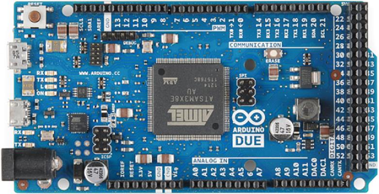
Figure 20.1 The Arduino Due
The USB connector adjacent to the power barrel, the Programming port, is a USB serial connector that is connected to an ATmega16U2 microcontroller which handles serial communication between the Arduino Due's main processor and the host computer. The other USB connector, the Native port, is connected directly to the SAM3X8E (see Figure 20.2). This means the Due has full control of this USB port, and can be connected as a slave for native serial communication. It is also USB OTG-compatible and can be connected to peripherals such as keyboards and mice using a special adapter.
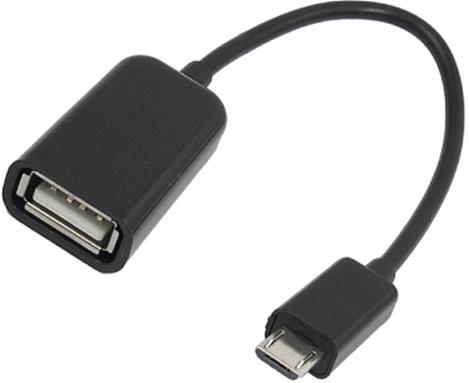
Figure 20.2 USB OTG connector
These adapters have a micro-USB connector on one side and a full-size USB connector on the other, allowing keyboards and mice to be connected.
The Arduino Due can use the USBHost library, a powerful library containing routines to use keyboards and mice as input devices, but it does come at a cost. USB drivers tend to be big. To reduce the size and complexity of the driver for use with a microcontroller, it's limited to talk only to a single device: a keyboard or a mouse. It cannot use USB hubs, and as such cannot talk to multiple devices or communicate with keyboards that have a built-in USB hub. This includes some specialized keyboards or keyboards with USB connectors for plugging in external devices.
USBHost Library
The Arduino 1.5 IDE comes with the USBHost library. To use it, you must first import it. This can be done in the menu: Sketch ![]() Import Library
Import Library ![]() USBHost. This imports quite a few libraries, as shown here:
USBHost. This imports quite a few libraries, as shown here:
#include <hidboot.h>
#include <hidusagestr.h>
#include <KeyboardController.h>
#include <hid.h>
#include <confdescparser.h>
#include <parsetools.h>
#include <usb_ch9.h>
#include <Usb.h>
#include <adk.h>
#include <address.h>
#include <MouseController.h>
To initialize the USB subsystem, you must create a USBHost object:
// Initialize USB Controller
USBHost usb;
The usb object can then be given to the different software structures. To process USB events, you must use the task() function.
usb.task();
The task() function waits for a USB event and calls the necessary function as those events happen. The function is blocking; while it is running, no other functions can run. If no event is received, it will time out after 5 seconds. If no device is connected, this function returns immediately, instead of waiting for a time-out.
Keyboards
Keyboards have their own controller, the KeyboardController class. First, you must attach the KeyboardController to the USB subsystem:
// Initialize USB Controller
USBHost usb;
// Attach Keyboard controller to USB
KeyboardController keyboard(usb);
When initialized, this class calls two functions when a specified event occurs. There are two events that can be identified by the class outside loop(): when a key is pressed and when a key is released. These do not include modifier keys; Shift, Control, Alt, and other such keys do not call these functions, but Caps Lock does.
The two functions are keyPressed() and keyReleased(). No parameters are passed to these functions; they must retrieve pending information from other sources.
// This function is called when a key is pressed
void keyPressed()
{
Serial.print("Key pressed");
}
This tells the sketch that a key has been pressed or released, but that is all. To know which key or combination of keys has been pressed, use getKey().
result = keyboard.getKey();
This function takes no parameters and returns the ASCII code of the key pressed. Not all keys can be printed as ASCII, and for this reason, another function is available, getOemKey().
result = getOemKey();
This function, unlike getKey(), does not return an ASCII code, but the OEM code associated with this key. This key can be one of the function keys or a multimedia key. It does not work on modifier keys: Shift, Alt, AltGr, Control, and so on. To get the status of modifier keys, use getModifiers():
result = keyboard.getModifiers();
This function returns an int, representing a bit field with modifiers, listed in Table 20.1.
Table 20.1 Modifier values
|
Modifier Key |
Value |
||
|
LeftCtrl |
1 |
||
|
LeftShift |
2 |
||
|
Alt |
4 |
||
|
LeftCmd |
8 |
||
|
RightCtrl |
16 |
||
|
RightShift |
32 |
||
|
AltGr |
64 |
||
|
RightCmd |
128 |
The modifiers listed in this table have been created as constants, and as such, can be used directly in your code.
mod = keyboard.getModifiers();
if (mod & LeftCtrl)
Serial.println("L-Ctrl");
Mice
Mice are just as easy to use as a keyboard, using similar techniques. To use a USB mouse, you must attach the MouseController to the USB subsystem, just like with a keyboard.
// Attach mouse controller to USB
MouseController mouse(usb);
Just like the keyboard controller, the mouse controller can also call functions. There are four of them: when the mouse is moved, when the mouse is dragged, when a button is pushed, and when a button is released.
void mouseMoved()
{
// Mouse has moved
}
void mouseDragged()
{
// Mouse was moved with a button pressed
}
void mousePressed()
{
// A mouse button has been pressed
}
void mouse Released()
{
// A pressed button has been released
}
To retrieve movement information, you use getXChange() and getYChange(). Both return int values, indicating the relative change in direction since the last time the mouse was polled.
Computer screens use a top-left coordinate system; the (0, 0) coordinate is in the top-left side (see Figure 20.3). The x- coordinate increases when going right and decreases when going left. The y- coordinate increases when going downward and decreases when going upward.
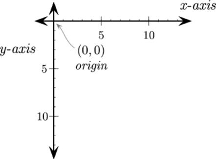
Figure 20.3 Computer graphics coordinates
The getXChange() function therefore returns a positive value if the movement is towards the right and a negative value if moving left. Likewise, the getYChange() function returns a positive value if moving upward and a negative value if moving downward.
To know which button was pressed or released, use getButton(). This function returns one of three predefined values: LEFT_BUTTON, RIGHT_BUTTON or MIDDLE_BUTTON.
Serial.print("Pressed: ");
if (mouse.getButton(LEFT_BUTTON))
Serial.println("L");
if (mouse.getButton(MIDDLE_BUTTON))
Serial.println("M");
if (mouse.getButton(RIGHT_BUTTON))
Serial.print("R");
Serial.println();
Example Program
In the early days of computers, there were no graphics. “Colossal Cave Adventure” was the game that started a whole new genre: computer adventure games. More like an interactive book, these games presented the user with a text representation and asked the user what to do, again, in text. Colossal Cave Adventure was so detailed that some people visiting the cave that it was based on actually recognized their surroundings.
The game recognized simple text commands and, through these actions, completed the story through several possible paths. You might get something like this:
1. You are in a small clearing. Butterflies dance in the sunlight, and there is bird song above. To the south there is a small stream, to the east you can see a small house, and to the north there is an apple tree.
2. > GO NORTH
3. You are under an apple tree. It provides comfortable shade from the sun, and the ground looks comfortable, more than enough for a quick snooze.
4. There is an apple in the tree.
As easy as it was to move around, the text system did have its limits. It wasn't possible to create sentences that were too complicated…
> IS THERE A WORM IN THE APPLE?
I'm sorry, I don't understand you. Please be more specific.
> I WANT TO KNOW IF THE APPLE IS EDIBLE
I'm sorry, I don't understand you. Try rephrasing that.
> IS THE APPLE RIPE?
I'm sorry, I don't understand you. Please be more specific.
> TAKE APPLE
You take the apple.
Early versions of the game actually saved time and size by analyzing the first five letters of any instruction; by using this method, the game could run on almost any computer. Later, as systems became faster, fans of the game developed versions in which each individual word was analyzed, and more complex orders could be given.
1. > HIT THE TROLL WITH THE SILVER SWORD
2. Well, he didn't see that one coming! The troll curls up into a ball, and turns back into rock.
More devious programmers had fun making games, turning some situations into textual nightmares:
1. > PUT THE RED GEM INTO THE BLUE SOCK AND PUT IT UNDER THE ALTAR
2. A voice echoes; Naribi accepts your gift! You hear a click from the other side of the door, and it slowly swings open.
Because the Arduino Due can accept a USB keyboard, it makes a perfect setup for some old-school games. You won't be designing an entire game; instead, these routines will concentrate on text input.
Remember, waiting for USB events can block the system for up to 5 seconds, so these routines will not be called all the time. They will be called only when the Arduino expects input and will continue to run until the last character is entered: the Enter key. After the text is entered, the Arduino can scan the individual words and then act according to some rules.
Hardware
This application runs on an Arduino Due because of the USB Host possibilities provided by this platform.
There are no external components for this project, with the exception of a USB keyboard, and a cable to convert the micro-USB port to a USB port. The other USB port will be connected to a computer to see the serial output. Serial communications will be at 9,600 baud.
Source Code
Time to write the sketch, as shown in Listing 20.1.
Listing 20.1: Sketch (filename: Chapter20.ino)
1 #include <KeyboardController.h>
2
3 // Key pressed
4 int curkeycode = 0;
5
6 // Initialize USB Controller
7 USBHost usb;
8
9 // Attach keyboard controller to USB
10 KeyboardController keyboard(usb);
11
12 void setup()
13 {
14 Serial.begin(9600);
15 Serial.println("Program started");
16 delay(200);
17 }
18
19 void loop()
20 {
21 keyloop();
22 }
23
24 // This function intercepts key press
25 void keyPressed()
26 {
27 curkeycode = keyboard.getKey();
28 }
29
30 // Sort the final sentence
31 void sortSentence(String sentence)
32 {
33 // Sentence logic goes here
34 Serial.println(sentence);
35 }
36
37 void keyloop()
38 {
39 String sentence = "";
40 bool waitforkey = true;
41
42 while (waitforkey == true)
43 {
44 // Process USB tasks
45 usb.Task();
46
47 // Look for valid ASCII characters
48 if (curkeycode >= 97 && curkeycode <= 122)
49 {
50 sentence += char(curkeycode);
51 Serial.write(curkeycode);
52 }
53
54 // Check for Return key
55 else if (curkeycode == 19)
56 {
57 Serial.println();
58 sortSentence(sentence);
59 waitforkey = false;
60 }
61
62 curkeycode = 0;
63 }
64 }
On the first line, the sketch loads the Keyboard controller library. This is the only library that will be required for this example.
The sketch defines an int, curkeycode. This variable holds the keycode from the keyboard; in most cases, it maps to ASCII, but it cannot be called ASCII because some keyboards can return non-ASCII characters. The return code will be checked later to see if it is ASCII. Until then, it is known as a keycode.
On line 7, the USB host is initialized, and on line 10, a KeyboardController object is created, and the previous USB object is passed to it. The USB host can now connect a keyboard to the USB subsystem.
On line 12, setup() is created, but all this does is configure the serial line. On line 19, loop() is created and is even simpler. It calls one function, keyloop(), over and over again.
There is only one keyboard event that will be of interest for this sketch: when a key is pressed. The sketch has no interest in when a key is released, so only one callback function is created: keyPressed(). This function simply updates the global variable curkeycode with the contents of the USB event.
On line 37, keyloop() is defined. This function is run whenever the sketch expects a keyboard input. First, an empty String is created, and then a boolean variable called waitforkey is set to true. While this variable is set to true, the USB subsystem waits for events. Awhile loop is created on line 42, and on line 45, the USB task function is run. This function either returns with an event or times out after 5 seconds. There is no way of telling exactly how this function ends, so the sketch looks at the contents of the variable curkeycode. If a valid ASCII character is detected (a keycode between 97 and 122), then the sketch adds that character to the end of the string. If the value 19 is received, then the sketch has received a return key press, so a new line is printed, and sortSentence() is called with the variable sentence, and the boolean variable is set to false, telling the loop that it is no longer expecting text input from a keyboard. If any other value is received, it is simply ignored. These include special characters, function keys, and control characters.
At the end of the while loop, the value of curkeycode is set to zero, an indication that the value has been read, and that the while loop expects a new value. Without this, the while loop might interpret this information as a key press, even if no key was pressed. Remember, the USB task function times out after 5 seconds, and then the rest of the sketch looks at the value of this variable. It has to be reset at the end of the loop.
While there's no logic for parsing the text you've entered in this example, sortSentence() is where you would write the code for figuring out the sequence of events in your text adventure story. To run this example, once you've uploaded the code to the Arduino, connect the keyboard to the Native USB port and your computer to the Programming port. Open the serial monitor and start typing away on the keyboard attached directly to the Due. You should see your words come up in the serial monitor once you press the return key.
Summary
In this chapter you have seen how the Arduino Due can be controlled by a USB keyboard and mouse. You have seen the functions used to get the status of inputs and to receive movement information. You have created the beginning of an interactive system allowing you to enter text to your Arduino. In the next chapter, you will see the Arduino Esplora and the library that is used to program this incredible device and use all the electronics present on this device.
All materials on the site are licensed Creative Commons Attribution-Sharealike 3.0 Unported CC BY-SA 3.0 & GNU Free Documentation License (GFDL)
If you are the copyright holder of any material contained on our site and intend to remove it, please contact our site administrator for approval.
© 2016-2026 All site design rights belong to S.Y.A.