Arduino Sketches: Tools and Techniques for Programming Wizardry (2015)
Part III. Device-Specifi c Libraries
Chapter 22. Robot
This chapter discusses the following functions of the Robot library:
· begin();
· motorsWrite()
· motorsStop()
· turn()
· pointTo()
· compassRead()
· updateIR()
· knobRead()
· keyboardRead()
· digitalRead()
· analogRead()
· digitalWrite()
· analogWrite()
· beginSpeaker()
· beep()
· playMelody()
· playFile()
· tempoWrite()
· tuneWrite()
· robotNameWrite()
· robotNameRead()
· userNameWrite()
· userNameRead()
· cityNameWrite()
· cityNameRead()
· countryNameWrite()
· countryNameRead()
· beginTFT()
· beginSD()
· drawBMP()
· displayLogos()
· clearScreen()
· text()
· debugPrint()
· drawCompass()
· parseCommand()
· process()
The hardware needed to use these functions includes:
· Arduino Robot
· 2 x TinkerKit connection cables and digital inputs
· Arduino Esplora (presented and programmed in Chapter 21)
You can find the code download for this chapter at http://www.wiley.com/go/arduinosketches on the Download Code tab. The code is in the Chapter 22 folder and the filename is Chapter22.ino.
Introducing Robot Library
Over the years, there have been several attempts to teach programming languages to children. Teachers and governments wanted to show children that programming isn't magic, and that simple logic is all that was required. The British Broadcasting Corporation, BBC for short, even went as far as to create its own computer for schools to accompany a television series on computer programming. It was a huge success and was just one of many projects. One of these projects was the Logo programming language.
Most programming languages are mathematical: the acquisition, modification, and use of numbers. Logo was different; it was based on logic. (Hence the name Logo is derived from the Greek word logos, thought.) Although designed for several reasons, an entire generation remembers it for the famous turtle.
The turtle was represented as a computer rendered triangle on our large cathode-ray tubes connected to primitive computers. The turtle was free to roam across the screen but needed instructions. For some unknown reason, it had a paintbrush strapped onto its tail. It could be told to put the brush down (to start drawing) or to pick it up (to stop drawing). It then required the user to give it instructions. Anyone who has used BASIC probably knows about the first program anyone writes:
10 PRINT "Hello, world!"
20 GOTO 10
This would print out endless lines of text and was a good visual start to programming but did not go any further. The turtle, however, was different. For example, take this program:
FD 100
RT 90
FD 100
RT 90
FD 100
ERT 90
FD 100
FD is short for forward. The turtle is instructed to advance for 100 “units” and then make a right turn (RT) by 90 degrees. Then it is instructed to advance another 100 units and so on. The result? A square as shown in Figure 22.1.
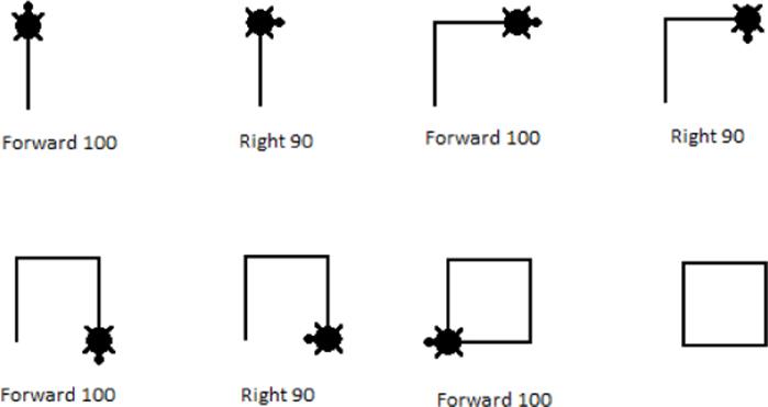
Figure 22.1 A square in Logo
Squares are basic, but Logo could create hugely complex structures and teach students about programming. Imagine a flower made up of eight petals. Each petal could be one “function” and called eight times by placing the turtle in the correct position. The results were visual, perfect for young children. A lot of us started off with Logo, and I can remember having great fun in the classroom with this.
One serious attempt was made to make the turtle “physical.” Created in the form of a large half-sphere, the turtle made it into the real world, but only for a short time. A turtle robot was made to show children just what could be done, but it was too early for the poor turtle. It was expensive, difficult to set up correctly, and required an exceptionally flat surface. The poor little turtle eventually disappeared, only a few programs exist today that still use it, either for teaching, or for simple nostalgia. Programmers returned to the digital world to see their little turtle. Some of us dreamed of seeing the little turtle return, and it has. Sort of.
Arduino Robot
Your Arduino Uno will be placed on your desk and will probably live there until your project is finished and you install it in its final resting place. I have one hidden behind my television, and it will stay there for quite some time. The Arduino Robot is different. It is the only Arduino that most certainly will not stay in the same place.
The Arduino Robot is an Arduino on wheels—literally. There are two large wheels on each side and two ball casters to keep it steady. It contains an impressive amount of electronics, but more important, it has enough space for you to add electronics and all the buses and connectors needed to connect components.
The Arduino Robot is, technically, two Arduinos in one. The motor board is controlled by an ATmega32u4 (the same microcontroller as on the Arduino Esplora) and contains flash memory, RAM, EEPROM, and two prototyping areas. It does not have a large amount of I/O, but what it does have is motor control circuits and power electronics to take standard batteries and power the two on-board motors. The control board on top uses the same microcontroller but has more I/O and adds a large array of electronics not seen on most other Arduinos. It has a keypad like the Arduino Esplora, an LCD screen connector that is compatible with the LCD module used on the Esplora, an 8-ohm speaker, a compass, and a large amount of external EEPROM via the I2C protocol (in addition to internal EEPROM). It also has four prototyping areas.
The Arduino Robot is a complex device, and care must be taken when preparing it. Unlike most Arduinos, there is some preparation required before using it for the first time: a protective cover must be placed under the device to protect it, drivers must be installed, and the optional TFT screen must be placed in the correct position, to name but a few. Arduino keeps an up-to-date webpage on the Arduino website at http://arduino.cc/en/Guide/Robot.
The Arduino Robot has two boards, and both are independent. They can be programmed separately, and both have a USB connector used for programming. Note that when programming the Arduino Robot, the electric motors are automatically disabled to prevent accidents. In order to fully use your sketch, you will need to power your device with batteries.
Generally, the control board is the only one that is programmed. The Arduino Robot has a number of functions that facilitate communication between the two. It is recommended to first use the control board and to program the motor board only when you are comfortable with the control board. If you make a mistake, don't worry; the stock motor program is available in the Arduino IDE as an example. The control board can tell the motor board to perform actions but also to read sensors on the motor board (like the infrared line following sensors on the bottom of the motor board).
Robot Library
The Arduino Robot library is a complicated library and depends on a number of external libraries, mainly for the infrared sensors and audio synthesis. These libraries have been merged into the Arduino Robot library to save space and do not need to be added manually. It also depends on some Arduino standard libraries for use. (Wire and SPI need to be included separately if using the functionality of those libraries.) To import the library, you must first decide which board you will be using because they do not require the same components. To create a sketch for the control board, add the Robot_Control library in Sketch ![]() Import Library
Import Library ![]() Robot_Control. This adds the following include declarations:
Robot_Control. This adds the following include declarations:
#include <Fat16mainpage.h>
#include <SdCard.h>
#include <ArduinoRobot.h>
#include <SdInfo.h>
#include <EEPROM_I2C.h>
#include <FatStructs.h>
#include <Fat16util.h>
#include <Fat16Config.h>
#include <Multiplexer.h>
#include <Fat16.h>
#include <Arduino_LCD.h>
#include <Squawk.h>
#include <Compass.h>
#include <Wire.h>
#include <Adafruit_GFX.h>
#include <SPI.h>
#include <SquawkSD.h>
#include <EasyTransfer2.h>
Not all these are required. Typically, you need only to include ArduinoRobot.h.
To create a sketch for the motor board, add the Robot_Motor library in Sketch ![]() Import Library
Import Library ![]() Robot_Motor. This adds the following include declarations:
Robot_Motor. This adds the following include declarations:
#include <ArduinoRobotMotorBoard.h>
#include <Multiplexer.h>
#include <EasyTransfer2.h>
#include <LineFollow.h>
Not all these are required. Typically, you need to include only ArduinoRobotMotorBoard.h.
Control Board
To use Arduino Robot control board, you must use functions from the RobotControl class. The functions are accessed through the object directly, so there is no need to call the constructor. However, to begin using the Arduino Robot-specific functions, you must first call begin():
Robot.begin();
begin()initializes interboard communication, sets variables to their correct values and other initializations for the Arduino Robot, but does not initialize the LCD screen or the speaker; other functions exist for those and are explained later in this chapter in the “LCD Screen” section.
Robotic Controls
The basis of any robot is, of course, movement. The Arduino Robot has an impressive amount of sensors, but its primary function is to move. The motor board has two independent motors, and although it is the motor board that drives these motors, the control board can instruct the motor board to perform actions.
To control the motors directly, use motorsWrite():
Robot.motorsWrite(speedLeft, speedRight);
This function takes two parameters: two int values. The speedLeft variable instructs the left motor at what speed it should rotate; accepted values range from –255 and 255. If the value is greater than 0, the motor turns forward. If the value is negative, the motor turns backward. If the value is zero, the motor stops. The speedRight parameter works in exactly the same way. This function does not return any data.
To instruct both motors to stop, use motorsStop():
Robot.motorsStop();
This function takes no parameters and does not return any data. It instructs both motors to stop immediately.
Turning can be achieved by varying the speed of rotation of the left and right motors. By varying the speed of each motor, you can achieve rotation, but the Arduino Robot goes a step further and has an embedded compass that can be used for greater accuracy. To tell the Arduino Robot to turn by a specific amount of degrees, use turn():
Robot.turn(degrees);
This function takes one parameter, an int, and accepted values are between –180 to 180. Negative values make the robot turn left; positive values make the robot turn right. Entering a value of zero has no effect. This function uses the on-board compass to get a bearing to magnetic north and then turns the robot by a specific number of degrees, verified by the compass. To make the robot turn to a specific heading, use pointTo():
Robot.pointTo(degrees);
Like turn(), pointTo() uses the compass to get its bearings, but instead of turning a specific amount of degrees, it tells the Arduino Robot to face a particular heading. It takes one parameter, degrees, which is the heading to face, where 0 is north, east is 90, south is 180, and west is 270.
The robot automatically decides if it should turn left or right, whichever is the shortest turn.
Sensor Reading
For robots to function correctly, they require multiple sensors. They need to know where they are and how they can interact with the world. You can add additional sensors to the Arduino Robot, but it already comes with a few sensors to get you started.
As seen previously, the Arduino Robot can be told to face in a specific direction, using the compass. You can also read the value of the compass using compassRead():
result = Robot.compassRead();
This function returns an int; the degrees of rotation from magnetic north.
NOTE
The Arduino Robot's compass takes readings relative to magnetic north, and the compass can be affected by magnetic fields. Make sure to keep your robot away from speakers, motors, or other strong magnets that could temporarily make the compass give false readings.
The motor board also contains five infrared sensors used for line following. The motor board can access the reading for the individual sensors, but with the control board, sketches must use updateIR():
Robot.updateIR();
This function takes no parameters and does not return any data. What it does is update an array, readable through Robot.Irarray[]:
Robot.updateIR();
for(int i=0; i<=4; i++)
{
Serial.print(Robot.IRarray[i]); // Print the value of each IR sensor
Serial.print(" ");
}
The control board also has a knob, a potentiometer. Powered by 5 V, it is connected to an analog-to-digital converter with 10-bit precision. It maps input voltages to an integer value between 0 and 1023, and is accessible through knobRead():
result = Robot.knobRead();
This function returns an int, the value read from the ADC.
The control board also has a five-button keyboard. These keys can be read through keyboardRead():
result = Robot.keyboardRead();
This function returns a constant reporting the button that is being pressed. See the possible values in Table 22.1.
Table 22.1 Keyboard Return Codes
|
Value |
Button |
|
BUTTON_LEFT |
Left button pressed |
|
BUTTON_RIGHT |
Right button pressed |
|
BUTTON_UP |
Up button pressed |
|
BUTTON_DOWN |
Down button pressed |
|
BUTTON_MIDDLE |
Middle button pressed |
|
BUTTON_NONE |
No button pressed |
The Arduino Robot contains TinkerKit connectors, both on the control board and on the motor board. Most of these ports can be read as both digital and analog, depending on the function call. Two functions can be called: digitalRead() and analogRead().
DigitalResult = Robot.digitalRead(port);
AnalogResult = Robot.analogRead(port);
The port parameter is a constant: the ID of the TinkerKit port to use. Accepted values are TK0-TK3, TKD0–TKD5, and B_TK1 to B_TK4. TK4 and TK5 are digital inputs only. digitalRead() returns either TRUE or FALSE. analogRead() returns integer values between 0 and 1023.
NOTE
Before reading the value of a TinkerKit port, make sure that a device is connected. Reading the value of a port where no device is present can result in unexpected results.
Of course, some TinkerKit ports are not used only for input, and the control board can also set TinkerKit outputs. To write digital output, use digitalWrite():
digitalWrite(port, value);
The value parameter is the value to write, either HIGH or LOW. The port parameter is the TinkerKit port, one of TKD0–TKD5, B_TK1–B_TK4, or LED1 (an LED located on the control board).
To write an analog value, use analogWrite():
Robot.analogWrite(port, value);
The value parameter is the analog value to write, ranging from 0 to 255. The output is not true analog; it is created using PWM, as with most Arduino analog outputs. The port value is the TinkerKit port to use; it can be used only on TKD4 and cannot be used at the same time as TK0 through TK7.
Personalizing Your Robot
I love all my Arduinos, but there is something even more lovable about computers that can follow you around. Just like a pet, it deserves a name and some personal information. This information can be stored in EEPROM and retrieved through special functions.
To give the robot a name, use robotNameWrite():
Robot.robotNameWrite(name);
The name parameter is a string and can be up to eight characters. The data will be stored into EEPROM and can be retrieved with robotNameRead():
Robot.robotNameRead(container);
In the following snippet, container is a char array and stores the result of the query.
char container[8];
Robot.robotNameRead(container);
Serial.println(container);
To tell the Arduino Robot your name, use userNameWrite():
Robot.userNameWrite(name);
The name parameter is a string and can be up to eight characters. As with the robot's name, the user's name can be retrieved using userNameRead():
Robot.userNameRead(container);
The container parameter is a char array.
There are two more things the Arduino Robot can read and write—the city name and the country name:
Robot.cityNameWrite(city);
Robot.cityNameRead(container);
Robot.countryNameWrite(country);
Robot.countryNameRead(container);
As with the previous functions, the write functions take strings, and the read functions require an 8-byte char array.
LCD Screen
The Arduino Robot control board has a connector for a TFT screen (the same screen as used on the Arduino Esplora). The Arduino Robot also has advanced functions to make the most of the screen.
To use the TFT screen, you must first call beginTFT():
Robot.beginTFT();
Robot.beginTFT(foreground, background);
By default, if called without any parameters, the TFT screen is configured with black as a background color and white as a foreground color. This can be changed by specifying the colors when calling beginTFT(). Valid colors are BLACK, BLUE, RED, GREEN, CYAN, MAGENTA,YELLOW, and WHITE.
The TFT screen module also contains a micro-SD card slot, and to activate it, use beginSD():
Robot.beginSD();
This function is required before using functions such as drawBMP() (explained next) and playFile() (explained in the “Music” section). Be aware that this library is fairly large and should be used only if you require the SD slot; complex sketches may have unexpected results if the SD card slot is initialized.
To draw a graphics file to the screen, use drawBMP():
Robot.drawBMP(filename, x, y);
The filename parameter is the name of the file located on the SD card. It must be in BMP format. The x and y parameters are the coordinates of the top-left corner of the image.
Displaying logos is often useful when starting a sketch, but the Arduino Robot library has a better solution. displayLogos() displays two logos on the screen:
Robot.displayLogos();
This function takes no parameters and automatically looks for two files on the SD card: lg0.bmp and lg1.bmp. This function first loads lg0.bmp and displays it on the TFT screen before waiting for 2 seconds. Afterward, it loads lg1.bmp and again waits for 2 seconds. These files are present on the SD card by default but can be replaced.
To clear the screen, use clearScreen():
Robot.clearScreen();
This automatically clears the screen using the default background color (black, unless specified otherwise).
It is possible to write text to the screen, using text():
Robot.text(text, x, y, write);
The text parameter can be a String but also an int or a long. The x and y parameters are the coordinates of the start position. The write parameter is a Boolean: true if the color to use is the foreground color (write) or false if the TFT screen uses the background color (erase).
To display debug information on the TFT screen, use debugPrint():
Robot.debugPrint(value);
Robot.debugPrint(value, x, y);
The value parameter can be either an int or a long. The x and y variables are optional and tell the function where to print the text. By default, the text will be printed on the top-left corner. This function not only prints a value, but also refreshes it, adding a unique debugging feature.
Another debug function, and a rather pretty one, is achieved with drawCompass():
Robot.drawCompass(degrees);
This function draws a compass on the TFT screen and shows the specified bearing, defined by the degrees parameter. Typically, this value is fetched with compassRead().
Music
The Arduino Robot has a built-in speaker on the control board, and numerous functions exist to take advantage of this component. You need to include the Wire and SPI libraries to use the speaker. To use the speaker, it must first be initialized with beginSpeaker().
Robot.beginSpeaker();
This function must be declared in setup().
The most basic form of sound is the beep and is made using beep().
Robot.beep(type);
The type parameter is one of three constants: BEEP_SIMPLE (a short beep), BEEP_DOUBLE (a double beep), or BEEP_LONG (a long beep).
To play simple music, use playMelody().
Robot.playMelody(melody);
The melody parameter is a string and describes the notes to be played, as well as their length. The notes are listed in Table 22.2.
Table 22.2 Melody Notes
|
Text |
Note |
|
c |
Play “C” |
|
C |
Play “C#” |
|
d |
Play “D” |
|
D |
Play “D#” |
|
e |
Play “E” |
|
f |
Play “F” |
|
F |
Play “F#” |
|
g |
Play “G” |
|
G |
Play “G#” |
|
a |
Play “A” |
|
A |
Play “A#” |
|
b |
Play “B” |
|
- |
Silence |
To set note length, use digits as described in Table 22.3.
Table 22.3 Note Length
|
Digit |
Duration |
|
1 |
Make the next notes full notes |
|
2 |
Make the next notes half-notes |
|
4 |
Make the next notes quarter-notes |
|
8 |
Make the next notes eighth-notes |
|
. |
Make the previous note ¾-length |
The Arduino Robot can make simple music, but it is also capable of more advanced playback, using playFile().
Robot.playFile(filename);
The filename parameter is the name of a file on an SD card. The SD card reader is located on the back of the LCD screen. As such, it requires the sketch to call beginSD() beforehand. The file must be in Squawk format, a special format resembling what was used on Amiga 500 computers. This file format can generally be created using Music Trackers. For more information, see the library README located on the project GitHub page at https://github.com/stg/Squawk.
These files contain music information and are played back at a precise speed and pitch. You can change both these parameters using functions. To change the tempo of a music file (to make it play faster or slower), use tempoWrite().
Robot.tempoWrite(speed);
The speed parameter is an int, the speed at which to play back the file. The default value is 50; lower values set the file to be played back slower, and higher values set the file to be played back quicker. This has no effect on the pitch; to change the pitch, usetuneWrite().
Robot.tuneWrite(pitch);
The pitch parameter is a float and indicates the pitch at which the file should be played back. The default value is 1.0; higher values set a higher pitch.
Motor Board
The motor board, placed underneath the control board, is responsible for controlling the two DC motors and reading the infrared sensors. It responds to instructions sent from the control board, but the default sketch can be modified to fit your use.
Just like the control board, to use the Arduino Robot motor board, you must use functions from the RobotMotor class. The functions are accessed through the object directly, so there is no need to call the constructor. However, to begin using the Arduino Robot-specific functions, you must again first call begin().
RobotMotor.begin();
To retrieve instructions from the control board, use parseCommand().
RobotMotor.parseCommand();
This function takes no parameters and does not return any data. It is used simply to read and update internal registers. After commands have been parsed, it is necessary to act on those instructions; this is achieved with process().
RobotMotor.process();
Again, this instruction does not take any parameters and does not return information. It operates the motors depending on the internal results of parseCommand().
These two instructions are, in fact, the basis of the default motor board sketch.
#include <ArduinoRobotMotorBoard.h>
void setup(){
RobotMotor.begin();
}
void loop(){
RobotMotor.parseCommand();
RobotMotor.process();
}
This sketch simply reads instructions from the control board and acts on those instructions. Why is there a separate board in this case? Although the microcontrollers on these boards are powerful, it is often a good idea to keep the functions separate; one microcontroller powers the control board, the other powers the motor board. The motor board performs instructions and continues to do so until instructed otherwise. The control board can perform advanced calculations or perform blocking functions while the motor board continues to monitor the DC motors.
Example Program and Exercises
The Arduino Robot is a superb platform and ready for tinkering. With a large number of inputs, it is easy and fun to create sketches giving your robot freedom of movement. For this application, you create a remote controlled Arduino Robot. For this, two TinkerKit digital inputs are used. TK5, placed on the left of the robot controls the left motor, and TK7 placed on the right controls the right motor. A logical 1 means that the motor turns, and a logical 0 stops the motor. These inputs will be read periodically. The speed of the wheels will be controlled by the potentiometer.
The sketch looks like Listing 22.1.
Listing 22.1: Sketch (filename: Chapter22.ino)
1 #include <ArduinoRobot.h>
2
3 void setup()
4 {
5 Robot.begin(); // Start the control board
6 }
7
8 void loop()
9 {
10 // Read in potentiometer values
11 int speed = Robot.knobRead();
12
13 // Potentiometer data is 0-1023, motors expect 0-255
14 // (we won't use negative values)
15
16 int motorSpeed = map(speed, 0, 1023, 0, 255);
17
18 // Motor variables
19 int leftMotor = 0;
20 int rightMotor = 0;
21
22 if (Robot.digitalRead(TK5) == true)
23 leftMotor = motorSpeed;
24
25 if (Robot.digitalRead(TK7) == true)
26 rightMotor = motorSpeed;
27
28 // Now control the motors
29 Robot.motorsWrite(leftMotor, rightMotor);
30
31 // Sleep for a tenth of a second
32 delay(100);
33 }
On line 1, the Arduino Robot library is imported. On line 5 in setup(), Robot.begin() is called. From here on, the user can call Robot functions.
loop() is declared on line 8. Because the motor speed will be controlled by the value of the potentiometer, the analog value is read in on line 11. This value is stored in an int called speed. The potentiometer gives values between 0 and 1023, but the motor control requires a value between 0 and 255. (Negative values are not used.) To adapt these values, map() is called on line 16; the result is stored in an int called motorSpeed.
Two new variables are declared on lines 19 and 20, and default values are assigned: 0. On line 22, the input of TinkerKit connector TK5 is read, and if this value is true, the user instructs the left motor to operate. If so, the value of leftMotor is set to motorSpeed, ordering the motor to turn forward. The same thing is done with the right-side motor on line 25. Finally, the motors are programmed on line 29 with motorsWrite().
Now that the motors have been activated or deactivated, the sketch waits for 1/10th of a second through a delay() on line 32 before continuing.
Multiple TinkerKit connectors are available, and you can use TK6 in the same manner to control the speaker. How about making the Arduino Robot beep on command to tell pesky cats and humans to get out of the way?
The TinkerKit inputs are set as digital but can also be set as analog, allowing the user to control the speed of the Arduino Robot. Change the inputs to make them analog.
Summary
In this chapter you have seen one of the most fascinating Arduinos, the Arduino Robot. You have seen the two boards that together make the Robot—the Control Board and the Motor Board. You have seen the library used to control both and how simple sketches can result in a fully functional mobile device. You have also seen how the Arduino Robot can use external sensors to be controlled. In the next chapter you will learn about the Arduino Yún and the Bridge library used to exchange messages between the Arduino microcontroller and a more powerful microprocessor running Linux.
All materials on the site are licensed Creative Commons Attribution-Sharealike 3.0 Unported CC BY-SA 3.0 & GNU Free Documentation License (GFDL)
If you are the copyright holder of any material contained on our site and intend to remove it, please contact our site administrator for approval.
© 2016-2026 All site design rights belong to S.Y.A.