Arduino Sketches: Tools and Techniques for Programming Wizardry (2015)
Part I. Introduction to Arduino
Chapter 3. Electronics Basics
You can have a lot of fun with an Arduino, but without some electronics, you won't get far. Without adding a single electronic component, you could program an Arduino Robot to run around racetracks, or program a games controller with an Arduino Esplora, but how about an Arduino Uno? Of course, you can add shields to add some functionality, but the real fun comes when you add your own electronics. This chapter shows you how to add your own electronics components onto an Arduino. No, don't run away! It is easy, I promise.
Electronics is often shrouded in mystery, conjuring images of highly complex and advanced components requiring weeks of calculating, just to choose the right one. Although some components are indeed incredibly advanced, and although some electronic circuits do indeed require weeks of work, this tends to be true in advanced fields, not basic electronics. At the end of this chapter, you will understand some basic electronic components, and you will be able to create your own electronic circuit.
Electronics is fun, but should be taken seriously. In this chapter, you will see a few warnings for particular components. Some components can't handle high voltage; others may be damaged or destroyed if handled incorrectly. Throughout this book, there are numerous electronic examples, but none of them use high voltage, AC voltage, or any other dangerous factors. Still, be careful! You will not hurt yourself with the 5 volts used in the examples, but a short circuit will damage any components in the circuit.
Electronics 101
Everyone is exposed to electronics in one way or another. You can find electronics inside your television, your computer, your washing machine, and just about any device in your house. The electronic boards inside a television are miniaturized, and look extremely complicated, but every electronic design follows simple laws of physics.
Electricity is the flow of electrons through a conductor. A conductor enables the flow of electricity, and an insulator does not. A resistor restricts the flow of electrical energy.
So, how do electronics relate to electricity? Electronics involve the use of components to manipulate electricity. This manipulation can be used to process information and build logical systems, among other things. For example, your home computer is filled with electronic components. It processes things like input from the keyboard, and by manipulating electricity it renders the characters you type on screen. When discussing circuits, it's good to keep in mind that there are two different types of supplying power. Alternating current (AC) is the type of electricity that comes from a wall socket. It's good for traveling over long distances (like from the power station to your home). In an AC circuit, the direction of electricity switches back and forth rapidly (60 times a second in North America, 50 times a second in most of the rest of the world) Direct current (DC) is the type of electricity for circuits you'll be building in the examples in this book. It's best suited for small electrical components like the ones you'll be using. In a DC circuit, electricity flows in one direction. In most devices in your home, like your personal computer or television, AC from the wall is converted to DC for use by the device.
Voltage, Amperage, and Resistance
Electrons are charged particles that naturally move from a location of higher potential energy to a location of lower potential energy. As the electrons move through a circuit, they can be harnessed to activate electronic devices to do work. Light bulbs, your television set, your coffee machine—all these devices function by harnessing the movement of electrons.
NOTE
A circuit is a closed loop that has a power supply and something to use the power (called a load). A power supply connected to itself without a load is called a short circuit, which can cause wires to melt or power supplies to catch fire.
When describing electricity, three measurements are used: voltage, amperage, and resistance.
· Voltage is the difference in electronic charge between two points.
· Amperage is the rate at which electrons flow past a point in a circuit.
· Resistance is the amount a component resists the flow of electrical energy.
Voltage
Voltage is defined as the amount of potential energy between two points in a circuit. In all circuits, the direction of the flow of electrons is determined by a location with higher potential electronic energy, and a point with lower potential energy. All available voltage will be used in a circuit.
It is possible to increase the amount of voltage in a circuit by placing power sources in series. For example, one AA battery typically has 1.5 volts of potential energy between the two ends. To have a potential energy of three volts, you can place two AA batteries end to end (so the “+” end of one touches the “-” end of the other). In this way, you would add the voltage of both batteries to create a power supply of three volts.
All electrical devices, have a voltage rating. The voltage rating describes the ideal voltage for that device. It also describes the type of circuit it is designed to be used with. In most cases, all the AC power sockets in your house provide the same voltage. Appliances and devices that are designed to plug into the wall are all rated for this sort of voltage. The power supply for the device will typically step-down the AC voltage to a DC voltage that is appropriate for the device. For example, my DVD player plugs into the wall, but the components inside run on 12 V DC. However, if you bought a device in the United States, flew across the Atlantic and tried to plug it into a socket in the United Kingdom, you may have an unpleasant surprise. Household electricity in the United States is 110V AC, and in Europe it is approximately 230V AC, depending on the country. Because all available voltage is used in a circuit, a device that is rated for 110 V will be overloaded trying to use the excess voltage in a 230 V socket and be damaged as a result. Some devices (like many laptop chargers) can automatically adapt between voltages, but many electronic devices cannot.
The Atmel ATmega328 microcontroller, found on the Arduino Uno, is an electronic device that can function between 1.8 V DC and 5.5 V DC. This describes the component's tolerance; it can function with a voltage between the two values. Typically, most devices connected to an Arduino won't work with voltages at the lower end of the range. To simplify design, the Arduino Uno has a voltage regulator: a device that accepts a wide range of input voltage from a power supply and provides a steady output voltage. In the case of the Arduino Uno, the input voltage can range between 6 V DC and 20 V DV and supplies a steady 5 V DC to the ATmega328 and any external components. Five volts is a common voltage for hobbyist electronics and some professional electronics. Some sensors and components use 3.3 V DC for power. The Uno has a separate regulator to power devices that require this voltage.
Providing too much or too little voltage to a component may damage it or destroy it.
Amperage
Amperage describes the amount of current in a circuit, which is the rate at which electric charge flows past a point in a circuit. It is measured in Amperes, or Amps. You'll be using components that use fractions of an amp in the projects in this book. It's common to use the analogy of water flowing through a pipe to illustrate the concept of electricity in a circuit. In this analogy, if voltage is the pressure forcing water through the pipe, amperage would be the amount of water flowing past a specific point in the pipe. The faster the water, the more current. Contrary to voltage, with amperage it is better to provide more than is required by the system because the system uses only the amount it needs.
To illustrate how current is used, imagine a simple circuit with a battery and a lamp. The lamp is the load in the circuit, and the battery is the power supply. The lamp runs off of 5 V DC and 20 milliamps (0.02 amps). The battery can supply up to one amp of current at 5 V DC. All the voltage will be used up, but the lamp will only use the amount of current it needs to turn on. Unlike extra voltage in a circuit, surplus amperage doesn't get used. If too little amperage is available, components will not work as expected: lights will dim, microcontrollers will reset, and all sorts of problems can result. Typically it's a good idea to use a power supply that provides at least two times the amperage your circuit needs.
Resistance
Resistance describes the ability for something to resist the flow of electrical energy. Materials with very high resistance are often used as insulators, like rubber and plastics. It's often necessary to regulate the flow of electrical energy through a circuit by increasing or decreasing resistance. For example, most LEDs used as indicators in hobbyist projects use less than the 5 V DC that the Arduino supplies. Placing a resistive element in series with the Arduino and the LED will decrease the voltage so the LED will function properly.
The practical unit of resistance is called the Ohm and is represented by the Greek letter omega (Ω). A resistance of 1 ohm is considered to be extremely weak, while a resistance of 1 million ohms is considered to be an effective insulator. Even if it's not stated in the documentation, all components have some resistance, even wires for carrying electricity.
Ohm's Law
One of the most frequently used formulas in electronics is Ohm's law, which states that the current that flows through a conductor between two points is directly proportional to the potential difference between the two points. Figure 3.1 depicts Ohm's Law.
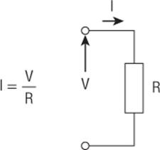
Figure 3.1 Ohm's Law
In this Ohm's Law formula, I is the flow of current, V is the potential difference, and R is the resistance of the conductor in ohms. For example, imagine a 50 Ω resistor placed on the ends of a 1.5 V AA battery. In this case, the formula would appear as shown in Figure 3.2.
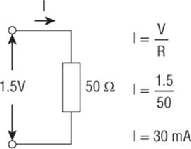
Figure 3.2 Ohm's Law example
I is unknown. However, both V and R are known, so I can be calculated. V is the voltage of the battery (1.5 volts) and R is the resistive value of the resistor (50). Knowing these two values, you can now calculate the current flowing inside the resistor—0.3 amps, or 30 milliamps.
The Basic Components
Looking at a circuit board, you might be afraid of all the different components on the board, all the different types…. How can you possibly understand all that? In truth, there are relatively few electronic components, and most are extremely simple to understand. There are a few complicated components, but they are rarely used and are mostly used in specific situations. The examples used in this book use only common components, ones that are readily available at most electronics shops, and their use is explained here.
Resistors
Resistors are electronic components designed to restrict the flow of electrical energy. There are different resistor values associated with varying resistors.
Different Resistor Values
Manufacturers cannot make every value of resistor possible, instead there is a standard range of values. The Electronic Industries Association (EIA) standard resistor values dictate the values of most resistors. Resistors use the following numbers: 10, 12, 15, 18, 22, 27, 33, 39, 47, 56, 68, and 82, in any power of 10. For example, you can easily find a 10 Ω resistor, or a 220 Ω resistor, or even a 4.7 kΩ resistor, but you will have great difficulty finding a 920 Ω resistor; the closest you will easily find is 820 Ω or 1000 Ω. How would it be possible to obtain a resistor with a value of 920 Ω? Putting resistors in series, that is to say one after the other, adds their values, so an 820 Ω resistor with a 100 Ω resistor combined is the same as a 920 Ω resistor, as illustrated in Figure 3.3. Examples in this book do not use resistors in series, instead standard values will be used. Resistors have various tolerances, typically deviating from 5% to 10% from their stated value.
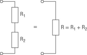
Figure 3.3 Resistors in series
Putting resistors in parallel, that is to say one next to the other, has a different effect on the value of the total resistance, as shown in Figure 3.4. Again, this configuration will not be used in the examples in this book and is here for reference only.
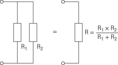
Figure 3.4 Resistors in parallel
Identifying Resistor Values
Resistors come in several shapes and sizes, but the ones that you will want to use for your examples are quite common, and can be identified as ¼ watt. This type of resistor has long legs to fit easily into a breadboard for rapid prototyping of circuits. Other kinds of resistors include surface-mounted resistors, available if you need to save space and are working on a printed circuit board, but they can be difficult to solder. The most common resistors look like the component shown in Figure 3.5.
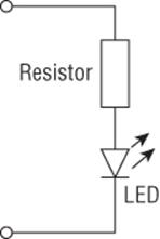
Figure 3.5 A common axial 10% tolerance resistor
Note the bands of color on the resistor; resistors are too small to put any readable text on and are color-coded to indicate their value. Typically, you'll find resistors with 4 stripes on them, though versions with 5 or 6 bands exist as well. Table 3.1 lists the color code.
Table 3.1 Resistor Color Code
|
Color |
Digit 1 |
Digit 2 |
Multiplier |
Tolerance |
|
Black |
0 |
0 |
x 100 |
|
|
Brown |
1 |
1 |
x 101 |
|
|
Red |
2 |
2 |
x 102 |
|
|
Orange |
3 |
3 |
x 103 |
|
|
Yellow |
4 |
4 |
x 104 |
|
|
Green |
5 |
5 |
x 105 |
|
|
Blue |
6 |
6 |
x 106 |
|
|
Violet |
7 |
7 |
x 107 |
|
|
Gray |
8 |
8 |
x 108 |
|
|
White |
9 |
9 |
x 109 |
|
|
Gold |
± 5% |
|||
|
Silver |
± 10% |
The first two bands indicate the value in ohms, the third band is a multiplier for scaling, and the fourth indicates how far the actual value may deviate from the stated value. A resistor with red, violet, orange, and gold stripes has a value of 2.7 KΩ; 2, 7, 103, and 10-percent tolerance. A 100 Ω resistor is brown, black, brown, and silver; 1, 0, 101, 10 percent.
NOTE
Color-blind people might be starting to worry here; don't. Whatever your color vision problems, I can assure you, you will be able to identify resistor values. I have acute achromatopsia, meaning that I see more or less in black and white. All colors are difficult for me to see. This was a problem during my studies, where teachers didn't know how to react, but today, this is never a problem for me. A simple ohmmeter or multimeter can quickly tell you the value of a resistor.
Using Resistors
The current and voltage can be regulated in an electronic circuit by resistors. Imagine an electronic circuit powered by a 5 V DC power supply. You want to add a Light Emitting Diode (LED) to show that the circuit is powered, in this case a red LED. This LED has avoltage drop of 1.7 V. A voltage drop means that the voltage of the circuit will be reduced by that amount. Therefore, if you were to place an LED directly between the +5 V and 0 V it would be damaged (remember, all voltage gets used up in a circuit). There must be a component to reduce the voltage across the LED, a resistor is the ideal candidate. The schematic of this circuit is shown in Figure 3.6.
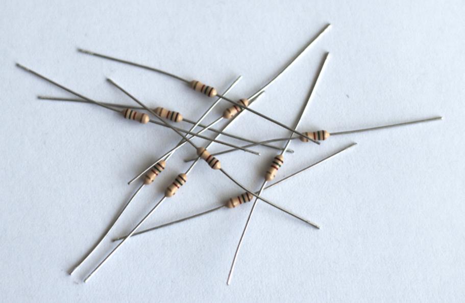
Figure 3.6 A resistor used to power an LED
Because you want 1.7 V across the LED, and because the circuit is powered by 5 volts, that means there should be a voltage drop of 3.3 volts across the resistor. Also, the LED is rated for 20 milliamps of current, but for this project 15 milliamps should be enough. Therefore, to have 15 milliamps flow through the LED, you will have to use a 220 Ω resistor. Another example is shown at the end of this chapter.
Capacitors
Where resistors are designed to resist electric current, capacitors are designed to store small amounts of electric energy.
Capacitors are composed of two parallel sheets of conductor separated by a thin nonconductor, which could be made from a number of materials, such as paper, mica, ceramic, plastic, and sometimes even air. When connected to electric potential, electrons are attracted into the capacitor and released when the outside voltage drops. A capacitor is, essentially, a small (and weak) rechargeable battery.
Capacitors come in many shapes and sizes and can be some of the smallest components available to the biggest, capable of dwarfing entire battery packs. Have you ever taken apart an electronic device and seen large, cylindrical components, normally in blue or black plastic? Chances are those are electrolytic capacitors, and you probably have not seen the biggest available.
WARNING
Some capacitors can be connected any way in a circuit; others must be placed in a certain way. Electrolytic capacitors especially have a polarity, and this must be respected. Failure to correctly polarize electrolytic capacitors can result in catastrophic failure; the component will leak or explode, potentially damaging the rest of your circuit. Don't try this at home!
The unit of capacitance is the farad (F). Most capacitors are in the microfarad range, but they can be as small as 1 picofarad (10-12 F) and as large as 104 F in supercapacitors.
Using Capacitors
If capacitors can store energy, how can this be used? First, capacitors can be used to regulate power lines, helping to filter out slight drops in power. Power lines are thought to be stable, but this is not always the case. Especially in motor systems, the power levels in power lines can vary. When motors start, they draw a lot of current, making the voltage temporarily drop. Adding capacitors onto the power supply helps filter out those drops and stabilizes the power for other components. These are described as decouplingcapacitors.
WARNING
Some capacitors can hold a large charge, and that charge is still there when you remove the power. Be careful when using these devices. Examples in this book are limited to 12V, which do not pose a threat, but larger devices like computer monitors and televisions can contain capacitors that store massive amounts of energy. Be careful!
One other use for capacitors, and one that is the most used on homemade electronics, is to help with one of the most basic components: buttons. A button is a simple mechanical device that will either make an electrical contact or break it. The problem is that these devices are not perfect, and pushing a button to make a contact often results in “bounces,” or unwanted spikes, when the metal inside the switch bounces on the contacts. By using a capacitor, the bounces can be filtered out.
Diodes
A diode is a small component that allows electricity to flow in only one direction. A perfect diode would not have any voltage drop and would not allow any electricity to flow in the opposite direction, but we don't live in a perfect world. Diodes do in fact have a voltage drop depending on the type of diode you use. A silicon diode like the 1N4148 have a voltage drop of approximately 0.65 V. Germanium diodes have a voltage drop of about 0.3 V.
Also, diodes have something called a breakdown voltage, the reverse voltage at which a diode conducts in reverse and most often breaks the component. The 1N4148 has a breakdown voltage of at least 100 volts, something that you will not encounter in the examples in this book, but it is useful to know.
Different Types of Diodes
There are many types of diodes. This book presents only the most common diode. Other types of diodes exist; Zener diodes have a specific breakdown voltage, and the breakdown state does not destroy the component. Schottky diodes have a low forward voltage drop. Tunnel diodes are extremely interesting because they use quantum tunneling and are used for advanced circuits.
There are also many other common diodes, ones that could deserve their own section. Laser diodes are special types of diodes that create laser lights; you can find these components in consumer electronics like CD players and Blu-ray recorders. Light-emitting diodes (LEDs) work in the same way, producing visible and nonvisible light and are presented in the next section.
Using Diodes
Diodes are used primarily to protect circuits either by avoiding a reverse-voltage or avoiding voltage spikes.
Electric motors can use large amounts of energy to make the motor spin. When there is an interruption of current flow inside the component motor, this can lead to a sharp rise in voltage across the device circuit. If the voltage drawn is beyond what the circuit is designed to handle, it may damage or destroy it.
Light-Emitting Diodes
Light-emitting diodes are exactly what their name implies; diodes, electronic components that let current flow in one direction only and that emit light. LEDs are used as indicators in home electronics, and have started to replace traditional incandescent light bulbs in home and industrial lighting. They are far more robust than light bulbs; they use less energy and exist in many different colors, shapes, and sizes.
Most LEDs emit a single-color with typical colors being red, orange, green, blue, and white. Dual-color LEDs also exist that can be either one of two colors or a mix between two colors, and finally, RGB LEDs exist that can take on almost any color by varying the red, green, and blue components.
LEDs also exist that emit nonvisible light: ultra-violet and infrared. Laser diodes are special types of light-emitting diodes, capable of creating laser light in various wavelengths and powers.
Using LEDs
Using LEDs is remarkably similar to their parent family: diodes. However, the difference is in their power consumption. Care must be taken not to supply too much current to an LED; otherwise it is possible to damage or even destroy the component.
LEDs have a larger voltage drop than their diode counterparts. Most common red LEDs have a voltage drop between 1.8 V–2 V, yellow LEDs 2.0 V, green LEDs 2.2 V, and blue LEDs can have up to a 3.4 V voltage drop. Typical maximum current for LEDs is around 20 mA for all LEDs, though blue versions can draw 30 mA. Your electronics distributor will have more information about the specific model you are using, so consult their documentation.
Transistors
Transistors are largely responsible for the proliferation of digital technologies, as well as many of the advances in computing power and size. A transistor is like a tiny switch but is solid state, meaning that there are no moving parts to wear out and can turn on and off much faster than any mechanical device. There are several sorts of transistors, but this tutorial talks only about the most common type in hobbyist electronics: the bipolar transistor.
Using Transistors
Although there are dozens of uses for transistors, examples in this book cover only one possible use: a switch.
Imagine an Arduino system powered by 5 volts. This system is designed to turn on and off an electric motor, one that needs to be powered by a 12-volt power supply. The motor also requires more current than the Arduino can supply. How can the Arduino possibly power a 12-volt motor using only a 5-volt output? The answer is, of course, by using a transistor as a switch.
A bipolar transistor has three leads. The Collector is connected to the positive side of the circuit, and the Emitter is connected to the negative side of the circuit, or the ground. Electrons will flow from the Collector to the Emitter, depending on the voltage at the Base. By supplying a relatively low voltage to the transistor's base, current can flow through the transistor into the collector and out of the emitter. In short, the transistor conducts current through the collector-emitter path only when a voltage is applied to the base. When no base voltage is present, the switch is off. When base voltage is present, the switch is on.
Breadboards
Electronics is fun; there is a joy in assembling components to do a required task; and it is hugely satisfying. When finished, some electronics are akin to digital art, in their function and in their implementation. Some circuit boards are a work of art in their own right, because of placing LEDs at strategic places, and cutting out the board to be the right shape. Have a closer look at your Arduino; notice the pictures printed onto the board, the picture of Italy, and imagine the time that was taken to make this board its current shape. It did take a lot of time, but that is also what frightens some people; do you really have to make one of these boards every time you make a design? Printed circuit boards like the Arduino and shields can either be made at home using some specialized equipment andchemicals, or fabricated professionally. Luckily, when prototyping, you don't need to do all that; there is a much simpler alternative: the breadboard.
Use of the term breadboard in this discussion may surprise you; normally it is a flat, wooden board designed to cut bread (or other foods). In the early days of amateur radio, amateurs would nail bare copper wire onto a wooden board (more often than not a breadboard which was readily available), and solder components onto the wires. Because components were much bigger in those days, some components (tubes especially) could actually be screwed onto the breadboard. Amateurs had created an easy prototyping device from an item readily available at any supermarket.
Modern breadboards are sometimes called solderless breadboards, implying that they can be reused. They exist in all sizes, from the smallest boards, designed to hold a single component, all the way to huge prototyping boards, designed to include an entire single board computer. Breadboards are normally classed by their number of connection points, the number of holes on the board that can accept wires and components.
Typical breadboards have two areas called strips. The terminal strip is the main part of any breadboard and is designed to hold components and wires. There is normally a notch in the middle, marking a separation between connectors, but it is also designed to allow air to flow beneath components helping them cool down.
The terminal strip is normally numbered: numbers horizontally and letters vertically. What is important to know is that a single number is connected to all the letters; A0, B0, C0, D0, and E0 are all connected electronically. A component pin placed in E0 connects to a wire connected to A0 but does not connect to a wire placed in A1.
The bus strip is located along the side of the terminal, and serves as a power rail. Normally, two rows are available: one for the supply voltage and one for the ground.
The holes are not placed at random; their spacing is exactly 0.1”, or 2.54 mm, accommodating many electronic components, and all Dual In-Line Package (DIP) chips. Most of the AVR chips exist in DIP format, making it possible to build an Arduino directly on a breadboard.
Inputs and Outputs
The Arduino's digital pins can be configured to be inputs or outputs to either write information or to read it.
There are two types of inputs on Arduino boards, digital and analog. On the digital pins, the Arduino “reads” either a logical zero (0 volts), or a logical 1 (equivalent to the power supply of the Arduino itself). Most Arduinos are powered by 5 volts, but a few are powered by 3.3 volts. If using a 3.3 voltboard like the Due, don't put 5 V on an input pin; you could damage the microcontroller. Note that in digital mode, there is a reasonable amount of tolerance; an input of up to 2 volts is still considered to be a logical zero.
On the analog pins, things are different. An analog signal has an infinite number of steps between zero volts and the power supply of the Arduino. In practice, it is not possible to sample an infinite amount of values, and the Arduino uses something called an Analog Digital Converter (ADC) to change the analog signal to a discrete number of steps. The Arduino's ADC has a resolution of 10-bits, which means there are 1,024 values that can be recognized on an analog input.
Connecting a Light-Emitting Diode
In this chapter, you have learned about basic electronic components, so now put that to the test. In this example, you control an LED placed on a breadboard, connected to an Arduino. The Arduino will be programmed to fade the LED. In this example, I will use an Arduino Uno and also a blue LED. Check the information about the LED you're using to determine the voltage and current requirements. The LED I'm using has a forward voltage of 3.4 V and pulls 30 mA of current.
Calculation
LEDs must be used with resistors, so the first thing that has to be done is to calculate the resistor that will be used. The Arduino Uno outputs 5 V DV, and the LED has a forward voltage of 3.4 volts; therefore, the resistor will have a potential difference of 1.6 volts. It will also let 30 mA of current pass. Because we know the amperage and voltage of the circuit, we can figure out the necessary resistance. My calculation is shown in Figure 3.7.
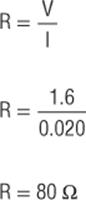
Figure 3.7 Calculating the resistor
Even though the LED is rated at an absolute maximum of 30 mA, you should try and aim for less than 30 mA of current. A safe bet would be to let 20 mA of current through the LED; that still makes it nice and bright and will not damage the component. For the time being, let's assume you want to let 30 mA of current pass through the LED, in which case the circuit would require a 53 Ω resistor. This is not a standard resistor value. The closest standard resistor value below 53 ohms is 47 ohms. If you do the math, you'll see that a 47-ohm resistor would allow 34 mA of current through the LED, above its rated tolerance. If you re-do the calculations aiming for 20 mA, the new result is 80 Ω. The closest standard value is 82 Ω, which is close to the target. Therefore, for this example, the schematic will use an 82 Ω resistor.
Software
It's time to code the application. This sketch illustrates a common beginner's task with the Arduino, fading an LED. Listing 3.1 presents the source code.
Listing 3.1:Fade
int led = 9; // the pin that the LED is attached to
int brightness = 0; // how bright the LED is
int fadeAmount = 5; // how many steps to fade the LED each loop
// the setup routine runs once when you press reset or power the board:
void setup() {
// declare pin 9 to be an output:
pinMode(led, OUTPUT);
}
// the loop routine runs over and over again forever:
void loop() {
// set the brightness of pin 9:
analogWrite(led, brightness);
// change the brightness for next time through the loop:
brightness = brightness + fadeAmount;
// reverse the direction of the fading when the LED is fully bright
// or fully off :
if (brightness == 0 || brightness == 255) {
fadeAmount = -fadeAmount ;
}
// wait for 30 milliseconds to see the dimming effect
delay(30);
}
The led variable is the pin the LED is connected to. You're using pin 9 because it is one of the PWM pins. That is, it is one of the pins you can call analogWrite() on. In the setup() function, the pin is set to become an output. Then, the loop() function adds the value stored in fadeAmount to the variable brightness, looks to see if the value should be inverted, and then waits for 30 milliseconds. Because this function is looped, it constantly updates the output pin value, ranging from 0 to 255, before returning back to zero. This will have the effect of starting with the LED completely off and then slowly increasing brightness to full before fading back to off.
Hardware
The code is done; the next thing to do is to actually create the circuit. This is only a prototype, so you will be using a breadboard. It is one of the simplest circuits you can build: two wires, one resistor, and one LED. The LED will be powered by the Arduino board.
First things first—the breadboard view. My view is shown in Figure 3.8.
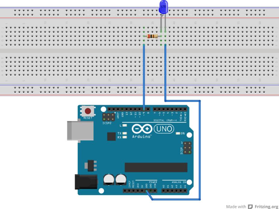
Figure 3.8 LED output (Image made with Fritzing)
After you re-create this circuit, you are now ready to upload your sketch to the Arduino, wait a few seconds, and look at an LED fading beautifully. Congratulations; you have just created your first hardware design! You now know how to create a sketch, and you know how to create an electronic circuit. The following chapters explain the different libraries in detail with example sketches and circuits to help you along your way.
What Now?
Now, it is all up to you. You might want to make this a permanent application in your house. Breadboards are good for prototyping, but a more permanent solution would require either creating a printed circuit board or maybe even an Arduino shield. A printed circuit board could be placed anywhere, and with enough wires, could even be placed far from the Arduino. You could put this outside in the garden as a night light, for example. Shields require being connected to the Arduino and therefore are not as easy to place outside. With a shield and an enclosure, you could make a night-light for a young child or even add a decoration in the living room. It is easy to add a few additional LEDs to this design to light up a cupboard or to illuminate a decoration. You can even make a small holiday display or welcome sign.
Summary
Welcome to the amazing world of Arduino! This chapter has given you a brief overview of electronics, enough to get you started with the projects contained in this book.
The following chapters explain some of the libraries that can be added to projects to give you an insight to what can be done. In Chapter 4 you will be using the standard library, which has the basic building blocks that you will see and use in every sketch. I will go through the different functions and explain how each one works.
All materials on the site are licensed Creative Commons Attribution-Sharealike 3.0 Unported CC BY-SA 3.0 & GNU Free Documentation License (GFDL)
If you are the copyright holder of any material contained on our site and intend to remove it, please contact our site administrator for approval.
© 2016-2026 All site design rights belong to S.Y.A.