Arduino Sketches: Tools and Techniques for Programming Wizardry (2015)
Part II. Standard Libraries
Chapter 4. The Arduino Language
Functionality can be added to Arduino programs using libraries, but every Arduino project invariably starts with one library; the Arduino Language. The Arduino Language contains everything required for basic programs, allowing access to input and output pins, mathematical functions, and control structures. This chapter lists those functions and gives an explanation of each one. You can also consult the Arduino reference page at http://arduino.cc/en/Reference/.
I/O Functions
An Arduino is a powerful system, but its power comes from interacting with the real world. To do this, the Arduino must use Input and Output, shortened to I/O. Pins can be defined as either being an input or output; it is up to you to decide.
Digital I/O
Digital I/O is defined as using a digital signal to communicate; a logical 1 or logical 0. In Arduino, 1 is defined as having a “high” voltage; normally at or close to the system voltage. 0 is defined as having a “low” voltage, typically 0. A system powered by 5 volts will usually have 5 volts for a logical 1 and 0 volt for a logical 0. A system powered by 3.3 V will usually have 3.3 V and 0.
Examples of digital inputs are switches, like push buttons or contact switches. They are either on or off; there are no values in between.
pinMode()
Before using a pin as a digital input or output, you must first configure the pin, which is done with pinMode(). pinMode() uses two parameters: pin and mode.
pinMode(pin, mode)
The pin parameter is simply the digital pin number you want to set. The mode parameter is one of three constants: INPUT, OUTPUT, or INPUT_PULLUP. The INPUT and OUTPUT constants set the pin to be a digital input or output, respectively. The INPUT_PULLUP constant sets the selected pin to become a digital input but also connects an internal resistor to keep the input level at a logical one if there is no input value.
By default, all digital pins are configured as INPUT, but it's considered best practice to explicitly declare the pinMode().
INPUT
Pins configured as INPUT can read voltage applied to them. It takes only a small amount of current to change an INPUT pin's state. The drawback to this is that pins configured as INPUT with nothing connected to them are more likely to change state due to electronic interference like static discharges. It is useful to use a pull-down resistor (going to ground) when connecting a switch to a pin configured as INPUT. Ten kilohm is a good resistor value for this.
INPUT pins are good at reading logical inputs but cannot be used to input, or sink, any current. For example, you cannot use an INPUT pin to sink current from an LED.
OUPUT
Pins configured as OUTPUT are capable of delivering power to circuits, up to 40 mA. This is more than enough to power an LED but is not enough to power motors. Output pins cannot read sensors. Connecting output pins directly to 5 volts or 0 volts can damage the pin.
INPUT_PULLUP
Pins configured as INPUT_PULLUP are configured as output, but with an internal pull-up resistor connected. On most Arduino boards this internal resistor is at least 20 kilohms. This has the effect of setting the input value to HIGH if it is pulled to ground, and LOW if voltage is applied.
digitalRead()
In order to read the state of a digital pin, you must use digitalRead():
result = digitalRead(pin);
The pin parameter is the pin number you want to read from. This function returns either HIGH or LOW, depending on the input.
digitalWrite()
To write the state of a pin that was declared as an OUTPUT, use the digitalWrite() function:
digitalWrite(pin, value);
The pin parameter is the pin number you want to write to, and the value is the logical level you want to write; HIGH or LOW.
Analog I/O
Analog is different than digital. Digital signals are one of two states; either true (a logical one), or false (a logical zero). Digital states are not designed to have any other value.
Analog is different in that it has a potentially infinite amount of values between two points. Analog is all around us. A light bulb is normally either on or off, but consider the sun. At nighttime, there is no light, and in daytime, midday, on a sunny day with no clouds, you would think that you have the maximum amount of sunlight. And during sunrise? You can see the amount of sunlight change visibly within a few minutes. During a cloudy day? There is light but not as much as during a clear day. This is no longer digital; it isn't on or off. The sun is analog; there are an infinite amount of possibilities.
Imagine a cruise ship. At the front of most large ships, there is a scale, a water line. It is used for several reasons, but to simplify, this marker serves to determine if a ship has been overloaded. Overloaded, a ship is at risk of sinking. The water line, technically called the Plimsoll Line, is where the water meets the hull. You can imagine that this line varies between two values: the minimum and the maximum. For this example, imagine between 20 feet and 40 feet. Right now, the ship you are watching is loading passengers, excited to sail to the Mediterranean. Slowly, the Plimsoll line rises: 30 feet, 31 feet, 32 feet…. And it stops at 33 feet. With a maximum Plimsoll line of 40 feet, this ship is safe to sail, but what is the exact value? 33 feet? Exactly? Probably not. It might be 33 feet and 1 inch, or maybe 33 feet and 3/8 of an inch? The point is, it doesn't matter. Humans aren't good with an infinite amount of values, and a docker looking at the ship will fill in the registry with 33 feet; he won't need absolute precision. It doesn't matter if a little bit is lost in the process.
Microcontrollers work in the same way. Microcontrollers are digital, but many can read analog values, including Arduinos. The device used to read analog is called an ADC, short for Analog to Digital Converter. The ADC cannot handle infinite values. It has aresolution. The Arduino divides the range into different equally sized portions. A 10-bit device can distinguish 210 different values—or a total of 1,024 different values. If used on a range between 0 and 5 volts; an input of 0 volts would result in a decimal 0; an input of 5 volts would give the maximum of 1,023. Something in between, such as 2.5 V would yield a value of 512. A 10-bit ADC can sense differences of 5 volts divided by the resolution, or 1,024. This device can therefore have an accuracy of 5 / 1,024, or roughly 0.005 volts.
analogRead()
To read a value from an analog pin, you call analogRead().
int analogRead(pin)
analogRead() reads the voltage value on a pin and returns the value as an int. The pin argument denotes the analog pin you want to read from. When referring to an analog pin, call them as A0, A1, A2,…A6.
This function takes approximately 100 microseconds to perform. In theory, you could sample a pin up to 10,000 times a second. However, it's best to let the ADC “settle” for a few milliseconds between reads for more accurate data acquisition.
analogWrite()
analogWrite() is used to write an analog output on a digital pin. Wait, analog? On a digital pin? Well, yes, sort of. It's not a true analog value that's being written.
Arduinos use something called Pulse-width modulation, PWM for short. PWM is digital but can be used for some analog devices. It uses a simple technique to “emulate” an analog output. It relies on two things: a pulse width and a duty cycle. It is a way of simulating any value within a range by rapidly switching between 0 volts and 5 volts.
The pulse width (also called a period) is a short duration of time in which the duty cycle will operate. The duty cycle describes the amount of time that the output will be at a logical one in the given period. Depending on the Arduino you're using, the period can range from 490 Hz to 980 Hz. A duty cycle of 50 percent means that during 50 percent of the pulse width, the output will be at a logical one, and the remaining 50 percent of the pulse width, the duty cycle will be at a logical 0. A duty cycle of 0 percent means that the output will always be p, and a duty cycle of 100 percent means that the output will always be 1.
PWM is an excellent method for controlling motors and dimming LEDs; it worked well in the previous chapter. However, some components do not like receiving pulses and want a stable output. For example, another Arduino reading an analog input would read in alternating values of 5 V and 0 V instead of a true analog signal. In this case, adding a capacitor to the circuit will “filter” the output.
Generating Audio Tones
Although most Arduinos are incapable of playing back advanced audio without additional electronics, they can play musical notes and tones natively.
Audio, or sound in general, is simply a vibration that propagates as waves of pressure. To generate sound, speakers and buzzers vibrate at certain frequencies to create sound.
Audio tones generated by Arduinos are variable frequencies, which can range from just a few Hertz up to 20 kHz, around the limits of human audition.
tone()
tone() is used mainly to generate audio tones on devices like buzzers. Although designed to generate audible tones, it is not limited to audio. This function generates a square wave, a signal that alternates instantly between two values, typically the maximum voltage and zero. It generates signals with a fixed 50 percent duty cycle, from frequencies as low as 31 Hz to 80 kHz (humans can typically hear up to 20 kHz). tone() accepts unsigned integers as a parameter.
This function requires either two or three parameters, depending on your use.
tone(pin, frequency)
tone(pin, frequency, duration)
The pin parameter is the pin number on which to produce a tone. The frequency parameter is the frequency to generate in hertz, passed as an unsigned int. Finally, the optional duration parameter is the duration of the tone in milliseconds, passed as an unsigned long. If this parameter is not specified, the tone will be generated indefinitely, or until the program tells the tone generation to stop.
noTone()
noTone() stops the square wave generation of tone() on the specified pin. If no tone is generated, this function has no effect. This function must be called before generating another tone on the same pin.
Reading Pulses
Arduinos can be told to react to pulses received on digital pins, reading serial data when data becomes available, or to call specific functions when a signal is received. However, in some cases, it is not the change in the signal that is important, but the time the signal stays at a logical state.
Imagine a sensor attached to your door. You want to know if the door was opened, and you want to know exactly how long the door was opened for. By adding a reed switch to your door, you can have a logical 1 (HIGH) if the door is closed, and a logical 0 (LOW) if the door is opened. How long was the door opened for? The Arduino can tell you.
pulseIn()
pulseIn() will tell you the length of a pulse. It requires a pin as a parameter and the type of pulse to read. When programmed, the Arduino waits for a signal on the selected pin. For example, you can tell the Arduino to wait for a pin to go HIGH. When it does, it starts a counter. When the signal returns to LOW, it stops the counter, and returns the number of microseconds. If no signal change is received within a set time, the function gives up and returns 0.
unsigned long length pulseIn(pin, value)
unsigned long length pulseIn(pin, value, time-out)
The pin parameter is the pin number to listen on, as an int value. The value parameter is the type of signal to wait for: either HIGH or LOW. The optional timeout parameter tells the Arduino how long to wait for a signal. It is an unsigned long and represents the amount of microseconds to wait. If omitted, it waits for 1 second before timing out.
pulseIn() is accurate within 10 microseconds when the time-out is up to 3 minutes long. Pulses longer than 3 minutes may be calculated inaccurately. Also, responding to interrupts can give inaccurate results because the internal timers are not updated during interrupt handling.
Time Functions
Timing is important in electronics projects. Electronics are not instantaneous, and most sensor components require some time before they can be accessed. A typical one-wire humidity sensor requires 100 ms of time between the command to acquire a reading and returning the result. Querying the component before it has had adequate time to complete its task could result in malformed data or cause the component to send a previous result. In either case, your sketch might not work as intended. Fortunately, Arduinos can patiently wait for a specified amount of time, by calling delay().
Another time function on Arduinos is the ability to get the time that the current sketch has been running. When an Arduino is powered on (or reset), two counters begins counting: the number of microseconds that the system has been running and the number of milliseconds.
delay()
delay() tells the microcontroller to wait for a specified number of milliseconds before resuming the sketch. This can be used to tell the microcontroller to wait for a specified period of time before reading a sensor, or slowing down a loop that is running too fast.
delayMicroseconds()
delayMicrosecond() is similar to delay(), but instead of waiting for a specified number of milliseconds, it waits for a specific number of microseconds.
This function is accurate to a certain point; values above 16,383 produce inaccurate results. If you need an accurate delay above 16,000 microseconds (or 16 milliseconds), use a mix of delay() and delayMicroseconds(), like in the following snippet of code, where the Arduino is asked to wait for 22.5 milliseconds, or a total of 25,500 microseconds.
delay(25); // waits for 25 milliseconds
delayMicroseconds(500) waits for 500 microseconds
millis()
millis() returns the number of milliseconds that the sketch has been running, returning the number as an unsigned long. This can be used to check how long the current sketch has been running, but it can also be used to calculate how long a function takes to run, by comparing the number of milliseconds before and afterward.
unsigned long timeBefore;
unsigned long timeAfter;
timeBefore = millis(); //Get the time before running a function
aLongFunction(); //Run a function that could take some time
timeAfter = millis(); //And now get the time after running the function
This data is stored in a counter that will overflow (go beyond the data capacity and return to zero) after approximately 50 days.
micros()
micros() is almost identical to the millis() function, except it returns the number of microseconds in an unsigned long. The counter overflows far more quickly than millis(); roughly every 70 minutes.
unsigned long time;
void setup(){
Serial.begin(9600);
}
void loop(){
Serial.print(“Time: “);
time = micros();
//prints time since program started
Serial.println(time);
// wait a second so as not to send massive amounts of data
delay(1000);
}
This function has a minimum number of microseconds that can be correctly evaluated. On Arduinos with a clock speed of 16 MHz, the resolution is 4 microseconds. On 8 MHz models, the resolution is 8 microseconds.
Mathematical Functions
The Arduino is a capable calculator, and the Arduino language has a large amount of mathematical functions to help you calculate. They can be used for simple calculations, to quickly analyze the voltage of one pin compared to another, or more advanced functions, to help robots move around and calculate the best path available.
min()
min() returns the smaller of two numbers.
result = min(x, y)
The two values can be of any numerical data type, returning the same data type as the parameter. This is used both as a way of knowing the smaller of two values and also to constrain data range; by using min(), you can make sure that an input value never goes over a certain value.
int sensorData = 100;
min(sensorData, 255); // Returns 100 (sensorData is smaller)
min(sensorData, 100); // Returns 100
min(sensorData, 64); //Returns 64
max()
max() is similar to min(), except it returns the higher of two values.
result = max(x, y)
max() can take any numerical data type and can be used to obtain a minimum value for sensor data.
int sensorData = 100;
max(sensorData, 255); // Returns 255
max(sensorData, 100); // Returns 100 (both values are the same)
max(sensorData, 64); //Returns 100 (sensorData is larger)
constrain()
constrain() is like combining parts of max() and min() at the same time; it constrains data values to a set range.
value = constrain(data, min, max)
Imagine a light sensor, reading the ambient light inside your living room, letting you turn the lights on or off. Values may vary between dark (you can still vaguely see your way around), and bright (comfortable to see, but not blinding). For a light sensor that gives values between 0 and 1,023, you could set the constrain levels to values between 40 and 127. Values below 40 are considered too dark to have a reliable reading, and values over 127 are too bright. What if a ray of sunlight hits the sensor? It would still be bright enough to see comfortably, but the sensor may return the maximum value: 255. Or what would happen if somebody covered the light sensor, for example, a cat and their incredible sense of disturbing scientific experiments by sleeping on your equipment? With no light at all, the sensor might return 0, and if you ever divide a value by your sensor reading, you could cause an error (because computers can't divide by 0). The following code will make sure you receive the sensor data, but constrained between values of 40 and 127 if the original sensor data was out of those bounds.
sensorValue = constrain(sensorData, 40, 127);
abs()
abs() returns the absolute value of a number, for example, the non-negative value of the number, without regard to its sign. The absolute value of 2 and –2 is 2.
value = abs(x);
This function is implemented in such a way that only values should be calculated, not the results from mathematical operations or functions.
abs(i++); // Do not do this, the result might not be what you expected
i++; // First calculate
abs(i); // Then use the result
map()
map() remaps a number in one range set to another. It takes a number, a theoretical boundary, and remaps that number as if it were in another boundary.
map(value, fromLow, fromHigh, toLow, toHigh);
This function takes a value called value in a range between fromLow and fromHigh, and remaps that value to a new range set by toLow and toHigh.
The clearest way to explain map() is with an example. Imagine a sensor, connected to an analog pin. It outputs numbers from 0 to 1,023. How would you convert this to a percentage? The map() function could do this in a single line.
result = map(sensorData, 0, 1023, 0, 100);
Mapping can also be used to invert value ranges:
result = map(sensorData, 1, 50, 50, 1);
pow()
pow() raises a number to the power of x.
double result = pow(float base, float exponent);
The base number and exponent are calculated as float, allowing for fractional exponents. The result of this calculation is returned as a double.
sqrt()
sqrt() calculates the square root of a number.
double result = sqrt(x);
The number x can be of any numerical data type, and the result is expressed as a double.
random()
Arduinos are capable of generating pseudo-random numbers using the random() function:
result = random(max);
result = random(min, max);
This function takes one or two parameters specifying the range for the random number to be chosen. If the min parameter is omitted, the result will be a number between zero and max, otherwise the number will be between min and max. The result is returned as a long.
Computers cannot generate purely random numbers, and instead use complex algorithms. While the output may indeed seem random, it is actually a sequence that is extremely long but always the same. To prevent your Arduino from always starting at the beginning, you can use the randomSeed() function to select where in that sequence to start:
randomSeed(seed);
The seed parameter is a long and can be any value you choose (either a fixed number or the amount of milliseconds that your sketch has been running).
Trigonometry
Trigonometry is a branch of mathematics that studies relationships between lengths and angles of triangles. Although some students might hate trigonometry at school, complaining that they will never need to calculate the side of a triangle in everyday life, the truth is that trigonometry is used in a great number of things we interact with every day. It is used in electronics, architecture, civil engineering, and a large number of fields.
Consider the triangle shown in Figure 4.1.
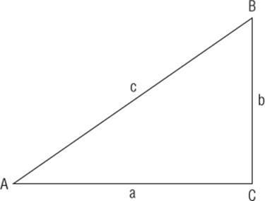
Figure 4.1 Right triangle
This triangle has three angles, called A, B, and C, and three sides, called a, b, and c. If the angle C is a right angle, that is, 90 degrees, you can calculate all the values with a little additional information. When dealing with right triangles, you can compute A, B, C, a, b, and c if you have the values for one side and one angle, or two of the sides.
Why would this be used? There are several reasons why you would want to use trigonometry with an Arduino. For example, the Arduino Robot could calculate a path around an obstacle if the angle and the distance are known. You could create a clock application on an LCD screen. Because you know the angle of the line (the hour), and the length of a line (a fixed value), you can apply the previous formula to draw the hour hand on-screen. In robotics, trigonometry is used extensively to know where the end of an arm will be based on calculations for every segment of the arm.
Trigonometry calculations on the Arduino are accomplished with sin(), cos(), and tan().
sin()
sin() calculates the sine of an angle in radians. The result is returned as a double between –1 and 1.
result = sin(angle);
Here, the angle parameter is a float, the angle in radians, and the function returns a double; the sine of the angle.
cos()
cos() calculates the cosine of an angle in radians. The result is returned as a double between –1 and 1.
result = cos(angle);
Once again, this function takes a single parameter, a float, the angle in radians, and returns a double.
tan()
tan() calculates the tangent of an angle in radians. The result is returned as a double.
result = cos(angle);
Constants
The functions used to calculate the sine, cosine, and tangent all require the angle to be expressed in radians, which isn't always what you have. Converting degrees to radians and back again is a simple mathematical formula, but the Arduino goes one step further, proposing two constants; DEG_TO_RAD, and RAD_TO_DEG:
deg = rad * RAD_TO_DEG;
rad = deg * DEG_TO_RAD;
Arduino also has another constant; PI, which of course is the familiar constant for π.
Interrupts
Interrupts are a way to respond immediately to external signals without having to spend a lot of time looking for changes.
Imagine you are at home, and you are waiting for an important parcel. This parcel will be delivered to your letter box without requiring a signature. The chances are that the postman will not knock on your door. You want to get your hands on it as soon as possible, so you go outside to look at the letter box frequently. It isn't there, so you wait for 10 minutes or so before having another look. You have to decide when to stop working (if you can actually work at all) before looking again, choosing a time that suits you. In computer terms, this continual checking for an event is known as polling.
Interrupts are different. A few days later, you wait for another parcel; only this time the parcel requires a signature, so the delivery man knocks on your door. This gives you a little more freedom. Because you don't have to waste time by looking inside the letter box every few minutes, you can get some work done. The delivery man will knock on your door to let you know that he has arrived, and at that time you can stop working for a few minutes to get your parcel. The downside to this is that you have to react quickly; if the delivery man does not get an answer quickly, he will go away. This situation is analogous to an interrupt.
Interrupts are a technique to let the processor continue working while waiting for an external event. It might not occur at all, in which case the main program continues, but if an external signal is received, the computer interrupts the main program and executes another routine, known as an Interrupt Service Routine, or ISR. ISRs are designed to be fast, and you should spend as little time as possible inside an ISR. When servicing an interrupt, some functions will not continue to work; delay() and millis() will not increment in interrupt context.
All Arduinos have interrupts; most use interrupts internally for serial communication or for timing counters. Some Arduinos have more user-programmable interrupts. Table 4.1 shows which interrupts are available on which pins for different models.
Table 4.1 Interrupt Pins on Arduinos
|
Board |
int.0 |
int.1 |
int.2 |
int.3 |
int.4 |
int.5 |
|
Uno |
2 |
3 |
||||
|
Ethernet |
2 |
3 |
||||
|
Leonardo |
3 |
2 |
0 |
1 |
7 |
|
|
Mega2560 |
2 |
3 |
21 |
20 |
19 |
18 |
The Arduino Due is different. It has highly advanced interrupt handling and can effectively be programmed to interrupt on every digital pin.
attachInterrupt()
This function specifies which routine to call when a specified interrupt is received.
attachInterrupt(interrupt, ISR, mode)
This function attaches a function to the interrupt number interrupt, depending on the status of the pin. The mode specifies the pin state to trigger the interrupt. Valid states are LOW, CHANGE, RISING, FALLING, or HIGH. ISR names the function you want to run. The ISR can be any function you write, but it cannot have parameters and cannot return information.
The Arduino Due has a slightly different prototype, as shown here:
attachInterrupt(pin, ISR, mode) // Arduino Due only!
detachInterrupt()
This function detaches a previously attached interrupt handler from attachInterrupt(). Interrupts on this ID will now be ignored. All other interrupts remain in place. It requires the interrupt ID to function.
detachInterrupt(interrupt);
This function is again slightly different for the Arduino Due; the Due requires the pin number to be specified, not the interrupt ID.
detachInterrupt(pin); // Arduino Due only!
noInterrupts()
noInterrupts() temporarily disables interrupt handling. This is useful when you are in an interrupt handler and do not want to be disturbed by other interrupts. It does have a down side; some system functions require interrupts, mainly communication. Do not disable all interrupts just because your code does not require user-made interrupt handlers. Disable interrupts only when there is timing-critical code being performed.
// Normal code
noInterrupts();
// Time critical code
interrupts();
// Normal code
interrupts()
interrupts() re-enables all interrupts. You do not need to reconfigure interrupt handlers; all interrupts will be reconfigured as they were before calling noInterrupts().
Summary
In this chapter you have seen the Arduino Language, a set of instructions and functions that are used on every Arduino and are available for every sketch. In the next chapter, you will see the functions used to communicate with the outside world through serial communications.
All materials on the site are licensed Creative Commons Attribution-Sharealike 3.0 Unported CC BY-SA 3.0 & GNU Free Documentation License (GFDL)
If you are the copyright holder of any material contained on our site and intend to remove it, please contact our site administrator for approval.
© 2016-2026 All site design rights belong to S.Y.A.