Arduino Sketches: Tools and Techniques for Programming Wizardry (2015)
Part II. Standard Libraries
Chapter 6. EEPROM
This chapter discusses the read() and write() functions of the EEPROM library. The hardware needed to run the examples in this chapter are an Arduino Uno and a USB cable.
You can find the code downloads for this chapter at http://www.wiley.com/go/arduinosketches on the Download Code tab. The code is in the Chapter 6 download and the filename is chapter6.ino.
Introducing EEPROM
Life would be boring if you had to reinstall software every time you turned off your computer. In the beginning, that is almost exactly what happened. A computer was turned on, and if a floppy disk was not inserted, the computer did not know what to do and just waited. It had no idea of who used it or what programs were available. Ironically, little has changed; instead of a floppy disk, we have hard drives, storing many times more data, but it still relies on the same principle.
Computers typically have two types of memory: volatile and nonvolatile. Volatile memory contains data as long as it is powered. When the power is removed, all the data is lost. This is how RAM works on your home computer. It uses a memory module called DDR. Actually; DDR memory is even more volatile than you might at first think; it needs to be refreshed frequently to keep the data in place. This might sound like poor engineering, but the truth is that Dynamic RAM (DRAM) is extremely fast, dense, and relatively cheap, allowing for inexpensive memory chips that work very well.
Volatile memory is used to store variables and data. The actual program is placed in nonvolatile memory and uses volatile memory to operate. Your alarm clock might have this function. You can set an alarm, but if the power is cut, you have to reprogram the alarm clock; otherwise, you won't wake up on time.
Nonvolatile memory is memory that retains data when power is removed. The first implementation of nonvolatile memory was an implementation of volatile memory with a small cell battery. When that battery ran out, the data would be lost. One solution to this was EPROM memory, as shown in Figure 6.1.
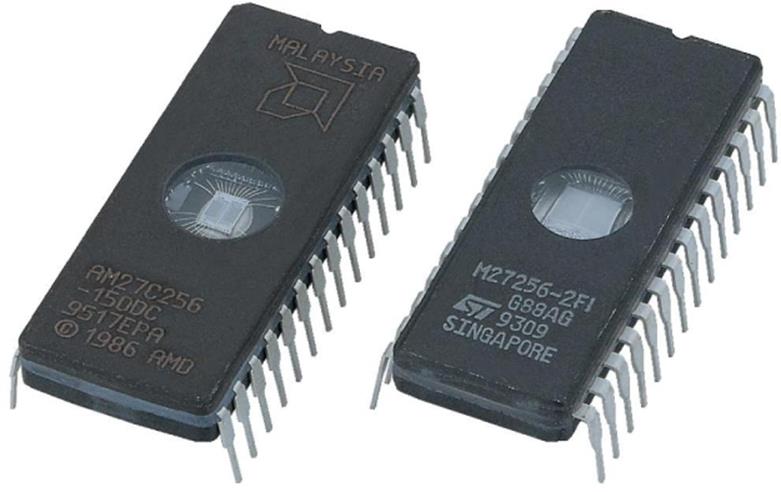
Figure 6.1 EPROM memory chip
Electrically Programmable Read Only Memory (EPROM) is a special memory that retains its data even when power has been removed. Early versions of EPROM required specialized equipment to be programmed. True ROM chips existed well before the arrival of EPROM, but EPROM added something that ROM chips did not have; they could be erased and reprogrammed.
Reprogramming the first EPROM chips was not something particularly easy to accomplish; these devices had a quartz “window” on the top of the chip. By placing the chip under ultraviolet light, the device could be erased within 20 minutes. When fully erased, the device could be reprogrammed.
Although such devices did work well, they were not always practical. They could store programs or nonvolatile variables, but devices became more intelligent and required an increasing number of parameters. How would you feel if your multimedia player couldn't change its name, IP address, or basic configuration? Something had to be done.
Electrically Erasable Programmable Read Only Memory (EEPROM) is a new generation of EPROM devices. EPROMs had to be removed from their circuit to be programmed or erased; however, EEPROM can be erased and reprogrammed in-circuit. Not only can they be reprogrammed, but also the erase and reprogram sequence can be applied to specific memory portions. In short, EEPROM devices can be modified byte by byte, providing an excellent method of storing long-term variables. Data retention for EEPROM devices is normally guaranteed for 10 to 20 years, but that is only a minimum. The real figure is normally much higher. Most EPROM devices were also guaranteed for 10 to 20 years, and a lot of systems built in the 70s are still working fine.
EEPROM does suffer from one flaw; writing data damages the device, ever so slightly. Don't panic! That doesn't mean that the device will stop working minutes after turning it on. Most EEPROM devices support at least 100,000 writes to the same byte, often much more. Writing data once a day to the same memory location will give a lifetime of at least 273 years. Remember; EEPROM is used for configuration data—data that does not often change, for example, serial numbers or IP addresses. Are you actually going to change your IP address 100,000 times?
EEPROMs are slower than other types of memory due to their technology. EEPROM cannot be written to directly; the memory must first be erased before bits can be written, and it is this erase phase that damages the device ever so slightly.
The Different Memories on Arduino
Arduinos have three different memory technologies: RAM, Flash, and EEPROM.
The RAM on Arduinos is exactly like the volatile memory on your computer; it is used to store variables, and the contents are lost when the power is removed.
The Flash memory is used for the sketch itself, as well as a small bootloader. This is the memory that is used when you upload a sketch. Previous contents are erased and replaced. Flash memory supports at least 10,000 write cycles.
The EEPROM memory is a slightly different memory technology, supporting more write cycles. EEPROM memory on ATmega microcontrollers support at least 100,000 writes and can be read and written to byte by byte. This is the memory that will contain long-term settings and is not overwritten by each flash. Updating your sketch won't overwrite your variables.
The EEPROM size varies for each microcontroller. The ATmega8 and ATmega168 found in early versions of the Arduino both have 512 bytes of EEPROM, and the ATmega328 in the Uno has 1,024 bytes. The ATmega1280 and ATmega2560 used in the different versions of the Arduino Mega both have 4 KB of EEPROM.
The EEPROM Library
The EEPROM library is a collection of routines that can access the internal EEPROM memory, reading and writing bytes. The EEPROM library can be imported by manually writing the include statement:
#include <EEPROM.h>
Optionally, you can add the EEPROM library using the Arduino IDE. Go to the Sketch menu item; select the Import Library submenu, and select EEPROM. This automatically includes the library, as shown in Figure 6.2.
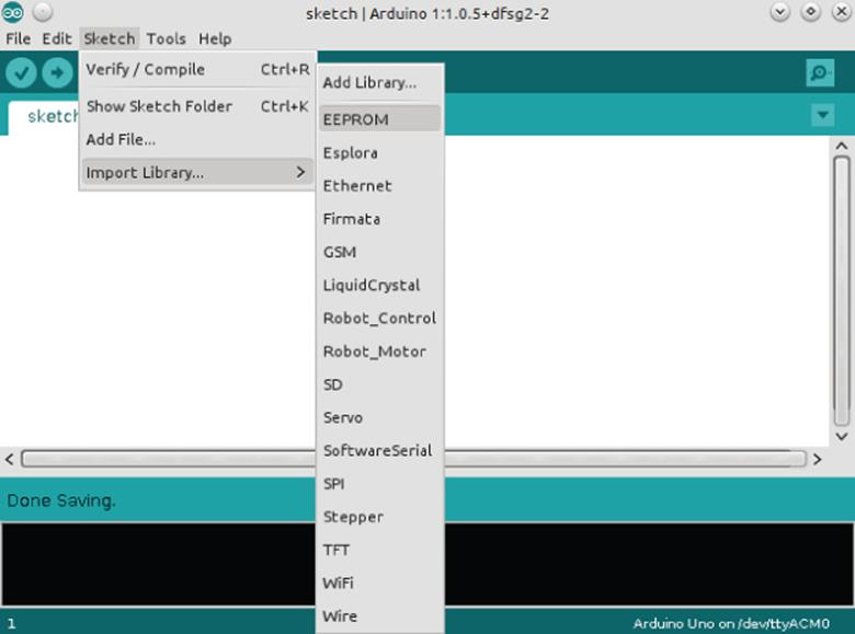
Figure 6.2 Importing the EEPROM library
Reading and Writing Bytes
The entire EEPROM library consists of two functions: read() and write(). These two functions can read and write bytes from specific memory locations.
The read() function reads data from a specified address adr, expressed as an int, and returns data as a byte.
EEPROM.read(adr);
The write() function writes a byte contained in data to a specific address adr. This function does not return any values.
EEPROM.write(adr, data);
The Arduino compiler automatically sets the correct start memory location. It doesn't matter if you use an Uno, Mega2560, or Mini; the compiler “translates” the correct address. Reading at memory location 0 read from the first byte of EEPROM.
Consider the following program:
byte value;
void setup()
{
// initialize serial and wait for port to open:
Serial.begin(9600);
while (!Serial) {
// wait for serial port to connect. Needed for Leonardo only
}
value = EEPROM.read(0);
Serial.print("Value at position 0:");
Serial.print(value, DEC);
Serial.println();
}
void loop(){}
In this program, the Arduino reads the first byte of EEPROM memory and displays it over the serial interface. Yes, it is that simple. Writing a byte into memory is just as straightforward:
void setup()
{
EEPROM.write(0, value);
}
void loop() {}
Writing a byte erases the byte in memory before rewriting, and this takes some time. Each write takes approximately 3.3 ms for each byte. Writing the entire contents of a 512-byte EEPROM device takes a little more than 1 1/2 seconds.
Reading and Writing Bits
Bits are used when using true/false values. In some applications there will be relatively few (or sometimes none at all), and in others, you will use boolean variables extensively. An Arduino cannot write individual bits to EEPROM; to store bits, they must first be stored in a byte. There are two possibilities.
If you have a single bit to store, the easiest way is just to code it as a byte, even if you use 1 out of 8 bits.
If you have several bits to store, you might want to try storing them all in 1 byte to save space, for example, a notification LED that the user can program as he wants. If this is an RGB LED, the user can choose a mix of any primary colors for notification. This can be coded into 3 bits; 1 for red, 1 for green, and 1 for blue. A logical 1 means the color is present, and a logical 0 means the color is not present.
You can define this as follows:
// primary colors
#define BLUE 4 // 100
#define GREEN 2 // 010
#define RED 1 // 001
Did you note that RED was defined as 1, and has the number 001 next to it? Arduinos, like all computer systems, store data as binary—a collection of ones and zeros. It is critical to understand binary when performing bitwise calculations.
Binary is a base-two system; that is to say that each digit can take one of two possible values—0 or 1. The rightmost figure corresponds to 20, the number to its left corresponds to 21, the next one to 22, and so on. In this example, I have used three specific values: 1, 2, and 4. I did not use 3 since in binary, 3 is written as 011, and I wanted each color to be assigned to a bit.
There are five more bits that could be coded into this byte. Each bit could indicate another behavior; maybe the LED should blink? Or maybe a warning beep? You can make this decision.
Also, another important part of bitwise calculations is AND and OR. In binary logic, a result is TRUE if one value AND the second value are both TRUE. TRUE and TRUE would result in TRUE, but TRUE and FALSE would result in FALSE. A result is TRUE if one value OR another value isTRUE. 1 OR 1 is TRUE, as is 1 OR 0, but 0 OR 0 is FALSE.
Let's imagine you want a cyan light to be lit up if something occurs. Cyan is a mix of green and blue. In English, you would say that you want green and blue, but in computer logic, you would say that you want GREEN or BLUE. A logical OR is true if one of the two values being compared is true. In this case, GREEN (010) is compared to BLUE (100), and the answer becomes 110.
So, the result, called CYAN, is 110, but now that you have encoded that, how can you get the data out of it? This time, you will be using a logical AND. A logical AND is true if the both the values being compared are true. So, CYAN AND BLUE? CYAN has a value of 110, and the value of BLUE is 100. The leftmost bit is 1 in both, so that will return as a 1. The second bit is 1 in CYAN and 0 in BLUE. It returns 0. The third bit is 0 in both values; it also returns 0. The result is 100. You can now say that BLUE is present in CYAN because the result was not zero. Now, time to try that again with RED. The value of CYAN is 110, and RED is 001. The first two bits are 1 in CYAN and 0 in RED. They return 0. The third bit is 0 in CYAN and 1 in RED. The logical AND process returns 000. There is no RED in CYAN because CYAN AND RED returns 0.
To read boolean data, read the byte containing the data from EEPROM and then perform a logical AND with the reference value. To create boolean data, you must take an empty variable (initialized as 0) and then perform logical OR operations with reference values. What happens if you want to update an existing value? You already know how to set a bit, using a logical OR, but to clear a bit, you must use a logical NOT AND. NOT inverts a status; if it was previously TRUE, it will become FALSE. By inverting the reference, you keep every bit that is set except the one you want to clear. To toggle a bit, simply use the logical XOR to invert its status. XOR, short for Exclusive OR, will be true if and only if one of the inputs is TRUE; if they are both TRUE, then the result will be FALSE.
Figure 6.3 shows a table of logical operators, showing the effect of each.
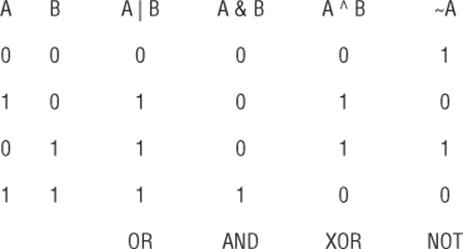
Figure 6.3 Logical operators
Following is a short example of how to perform bitwise operations. A bitwise OR is performed using the | symbol:
value |= RED; // Bitwise OR. Sets the BLUE bit
To perform a bitwise AND, use the & symbol:
vavalue &= ˜GREEN; // Bitwise AND. Clears the RED bit (AND NOT RED)
And finally, to perform an exclusive OR, use the ^ symbol:
value ^= BLUE; // Bitwise XOR. Toggles the GREEN bit
Reading and Writing Strings
Strings are generally an array of char values and as such can be easily stored and recalled. In Arduino, it's possible to use a char array as a string, or you can use the String data type for more robust data manipulation, at the cost of program size. With character arrays, you can recall the entire allocated memory and print it out as required.
Suppose you need to store a string, defined as such:
char myString[20];
You can also set a string to a specific value when you declare it. Note that while this array can contain up to 20 elements, not all of them have data.
char myString[20] = "Hello, world!";
You can store information in EEPROM like this:
int i;
for (i = 0; i < sizeof(myString); i++)
{
EEPROM.write(i, myString[i]);
}
This routine will write the contents of the string to EEPROM memory, one byte at a time. Even if the string is only 5 bytes long, it will store the contents of the entire array. That is, if you declare a char array of 20 elements and only have valid data in the first 5 bytes, you'll still be writing 20 bytes to EEPROM. You could make a more optimized routine that automatically stops when it receives a null character: the end of a C string, but because this routine writes to EEPROM memory that is not often (if ever) changed, there is no point to over-complexifying the program. Reading a string is just as easy:
int i;
for (i = 0; i < sizeof(myString); i++)
{
myString[i] = EEPROM.read(i);
}
Again, the operation is the same; it will take 1 byte from EEPROM and place it into the string, and repeat for each byte in the string.
Reading and Writing Other Values
If the EEPROM can only read and write bytes, how can you save the contents of an integer or a floating point number? At first it might seem impossible, but remember that in computers, everything is just 1s and 0s. Even a floating-point number is written in memory as binary, it just occupies a larger number of bytes. Just like with strings, it is possible to write just about anything in EEPROM memory, by reading and writing 1 byte at a time.
Before beginning, you must know exactly what sort of data you need to read and write. For example, on all Arduinos except the Due, an int is written as 2 bytes. By using techniques known as shifts and masks, it is possible to “extract” bytes of data. Shifting takes a binary number and “shifts” data to the left or to the right by a certain number of bits. Masking makes it possible to perform bit-wise operations on a portion of a binary number. Take the following example:
void EEPROMWriteInt(int address, int value)
{
byte lowByte = ((value >> 0) & 0xFF);
// Now shift the binary number 8 bits to the right
byte highByte = ((value >> 8) & 0xFF);
EEPROM.write(address, lowByte);
EEPROM.write(address + 1, highByte);
}
In this example, an int is to be saved into EEPROM. It contains two bytes: the low byte and the high byte. The terminology “low” and “high” bytes is used when a number is stored on several bytes; the low byte contains the least significant part of the number, and the high byte contains the most significant part of the number. First, the lowest byte is extracted. It simply takes the number and performs a bitwise AND with 0xFF. The 0x in front of the letters tells the Arduino IDE that this is a hexadecimal number. Just like binary, hexadecimal is another way of printing a number. Instead of using only two values per figure, hexadecimal uses 16. 0xFF is the hexadecimal representation of 255, the largest number that a byte can hold. Then, the same value is shifted right 8 bits, and again, an AND is performed. This is an elegant solution that can work for integers but will not work for more complex numbers, like a floating-point. You cannot perform shifts with a floating-point, more advanced techniques are required.
Several users have requested EEPROM functions to write any sort of data, one possible solution is available in the Arduino Playground and is called EEPROM Write Anything. If you want to write anything to EEPROM, look at this example from the playground—but be forewarned, it uses advanced programming techniques that are not covered in this book:
http://playground.arduino.cc/Code/EEPROMWriteAnything
Here is an extract of this code:
template <class T> int EEPROM_writeAnything(int ee, const T& value)
{
const byte* p = (const byte*)(const void*)&value;
unsigned int i;
for (i = 0; i < sizeof(value); i++)
EEPROM.write(ee++, *p++);
return i;
}
Again, this code requires specific information: the exact size of the value to save. Be careful when using int values; again, on the Arduino Due, they are a different size than other Arduino boards.
Where possible, try to use byte-size values, but as you can see, it is possible to store just about anything in EEPROM.
Example Program
In the previous chapter, you created a program that would greet the user, ask for his name and age, and write some data to a serial port. However, when the Arduino was unplugged, it forgot everything; the next time it was powered on, it would ask for the same information. We'll build on that same program but now store the responses in EEPROM. The Arduino should first check its EEPROM memory. If no information is found, it will ask the user some questions and then store that information into nonvolatile memory. If the information is found, it will tell the user what information it has and then delete the contents of its memory. It is now clear that an Arduino knows its ABCs, so I removed that portion of code from the example. The program is shown in Listing 6.1.
Listing 6.1: Example program (code filename: Chapter6.ino)
1 #include <EEPROM.h>
2
3 #define EEPROM_DATAPOS 0
4 #define EEPROM_AGEPOS 1
5 #define EEPROM_NAMEPOS 2
6 #define EEPROM_CONTROL 42
7
8 char myName[] = {"Arduino"};
9 char userName[64];
10 char userAge[32];
11 unsigned char age;
12 int i;
13 byte myValue = 0;
14
15 void setup()
16 {
17 // Configure the serial port:
18 Serial.begin(9600);
19
20 // Does the EEPROM have any information?
21 myValue = EEPROM.read(EEPROM_DATAPOS);
22
23 if (myValue == 42)
24 {
25 // Get the user's name
26 for (i = 0; i < sizeof(userName); i++)
27 {
28 userName[i] = EEPROM.read(EEPROM_NAMEPOS + i);
29 }
30
31 // Get the user's age
32 age = EEPROM.read(EEPROM_AGEPOS);
33
34 // Print out what we know of the user
35 Serial.println("I know you!");
36 Serial.print("Your name is ");
37 Serial.print(userName);
38 Serial.print(" and you are ");
39 Serial.print(age);
40 Serial.println(" years old.");
41
42 // Write zero back to the control number
43 EEPROM.write(EEPROM_DATAPOS, 0);
44 }
45 else
46 {
47 // Welcome the user
48 Serial.println("Hello! What is your name?");
49
50 // Wait until serial data is available
51 while(!Serial.available())
52 // Wait for all the data to arrive
53 delay(200);
54
55 // Read in serial data, one byte at a time
56 Serial.readBytes(userName, Serial.available());
57
58 // Say hello to the user
59 Serial.print("Hello, ");
60 Serial.print(userName);
61 Serial.print(". My name is ");
62 Serial.print(myName);
63 Serial.println("\n");
64
65 // Save the user's name to EEPROM
66 for (i = 0; i < sizeof(userName); i++)
67 {
68 EEPROM.write(EEPROM_NAMEPOS + i, userName[i]);
69 }
70
71 // Ask for user's age
72 Serial.print("How old are you, ");
73 Serial.print(userName);
74 Serial.println("?");
75
76 // Wait until serial data is available
77 while(!Serial.available())
78 // Wait for all the data to arrive
79 delay(200);
80 age = Serial.parseInt();
81
82 // Print out the user's age
83 Serial.print("Oh, you are ");
84 Serial.print(age);
85 Serial.println("?");
86 Serial.print("I am ");
87 Serial.print(millis());
88 Serial.println(" microseconds old. Well, my sketch is.");
89
90 // Now save this to EEPROM memory
91 EEPROM.write(EEPROM_AGEPOS, age);
92
93 // Since we have all the information we need, and it has been
94 //saved, write a control number to EEPROM
95 EEPROM.write(EEPROM_DATAPOS, EEPROM_CONTROL);
96 }
97
98 }
99
100 void loop()
101 {
102 // put your main code here, to run repeatedly:
103 }
So, what has changed? Well, the most visible change is that the code concerning Arduino's ABC recital has been removed. This example concentrates on something else.
On line 11, the user's age is now stored in an unsigned char. Originally this was stored in an int, but this presents a problem for EEPROM memory. Remember that in Chapter 4 you saw that int values stored from –32768 to 32767. You won't need all those numbers; humans don't (yet) live that long, and in any case, negative numbers aren't necessary. The problem isn't the range; it is the size of the container. On most Arduinos, an int is coded on 2 bytes (in the Due it occupies 4 bytes). If you release your program as open source, you will have no way of knowing which Arduino will be used. In addition, an int for an age is a bad idea; it isn't optimal. An unsigned char is always 1 byte and can handle numbers from 0 all the way to 255. This will be easier to write to an EEPROM.
On line 21, the sketch reads data from the EEPROM. The exact location is defined by EEPROM_DATAPOS. Of course, the function could have been called directly with the number 0 (and this is exactly what the compiler is going to do), but adding a #define makes the code more readable and also allows the developer to change memory location without worrying about forgetting a call. This makes everything neater. This sketch shows the persistence of nonvolatile memory, and as such, it has to have a way of ignoring any data stored. To do this, a “control” byte is allocated. The Arduino reads a value in the EEPROM. If it receives the number 42, it presumes that the EEPROM contains valid information and attempts to read that data. If the Arduino reads any other number, it asks the user for information, writes that data to EEPROM, and then writes the control byte.
Assuming that no valid EEPROM data has been found, the sketch is close to what was already present in the previous chapter. On lines 50 and 76, the serial call has been changed. At the end of the previous example, I asked you to try and find a better way of listening for serial communication. This is one way of waiting for serial data. What did you find?
On line 91, the sketch saves the contents of the variable age to EEPROM using a single function call: EEPROM.write(). However, on line 65, the string userName is saved 1 byte at a time. The entire string memory is written to EEPROM, but you could tweak the code to write only what is needed. What would you write?
This brings the question: How do you organize memory? It is up to you, the engineer and creator, to decide how the memory will be partitioned. This example used position 0 as the control byte, position 1 as the age, and 20 bytes from position 2 onward as a string containing your name. Don't hesitate to use a spreadsheet or some paper notes to map out your memory, to know what will go where. An example is shown in Figure 6.4.
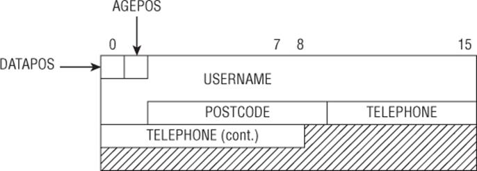
Figure 6.4 Memory organization
Keep in mind that #define statements are easier to change rather than looking through your code if you need to change something.
Preparing EEPROM Storage
One of the problems encountered with EEPROM memory happens the first time a sketch is run. This sketch assumes that if a certain number is present in the first block, then the rest of the information is valid. When running this sketch on another system, you do not know what EEPROM contains. If you are unlucky, the first byte will already contain the control number you're looking for, but the rest of the data may not contain a valid age, or a valid name. This could simply result in garbled text, but in another application, it might lead to significant problems. Imagine a small sensor that connects to the Internet to upload temperature readings to a server. If the IP address is stored in EEPROM, and that memory location does not contain valid data, then your application will attempt to upload data to a server that does not belong to you.
To prevent this, some designers add a reset button to their project. By adding a few lines to your sketch, you can erase EEPROM data in the case of a first-time power on, or if the Arduino board were changed. Some applications use the control number for error checking, adding several numbers throughout EEPROM memory for more reliability. Or, you could use a second sketch, one that you upload that sets EEPROM data exactly as you want, before reflashing the final sketch. There are several solutions available; it all depends on what solution is the best for you and your application. Don't trust EEPROM contents on a new system; take the time necessary to prepare the nonvolatile memory.
Adding Nonvolatile Memory
Arduinos have limited EEPROM memory that is sufficient for most programs, but in some cases you might need to add EEPROM memory. Numerous EEPROM components exist, for example the Atmel AT24C01A that adds 1 KB of memory, or the AT24C16A that adds 16 KB of memory. However, these components are connected to the I2C bus (explained in Chapter 8) and cannot be addressed by the EEPROM library. The EEPROM library can handle only the internal EEPROM, not external. If you want more external memory, it must be addressed by the bus that it uses.
If you require large amounts of nonvolatile memory, other solutions exist. Arduino shields exist that can accept SD or micro-SD cards. At the time of writing, micro-SD cards have capacities up to 128 gigabytes, more than enough for most logging applications.
SD cards are based on flash memory, and as such, also inherit flash memory's weakness: write cycles. However, most SD cards have an internal controller that implements something called wear leveling, a technique used to limit the amount of write cycles to a specific place in memory. This greatly increases the life expectancy of the flash memory, allowing for normal filesystem use, even when files are frequently updated. If you need nonvolatile memory that is often changed, consider using an SD-card shield. SD-card operation is explained in Chapter 12.
Summary
In this chapter, you have seen how to read and write data to and from an Arduino's internal EEPROM memory. In the next chapter, I will explain SPI communications, another form of serial communication used to talk to sensors and exchange information.
All materials on the site are licensed Creative Commons Attribution-Sharealike 3.0 Unported CC BY-SA 3.0 & GNU Free Documentation License (GFDL)
If you are the copyright holder of any material contained on our site and intend to remove it, please contact our site administrator for approval.
© 2016-2026 All site design rights belong to S.Y.A.