Arduino Sketches: Tools and Techniques for Programming Wizardry (2015)
Part II. Standard Libraries
Chapter 7. SPI
This chapter discusses the following functions of the SPI library:
· begin()
· end()
· setBitOrder()
· setDataMode()
· setClockDivider()
· transfer()
The hardware needed to use these functions includes:
· Arduino Due
· Adafruit MAX31855 breakout board
· Type-K thermocouple wire, from Adafruit Industries
You can find the code download for this chapter at http://www.wiley.com/go/arduinosketches on the Download Code tab. The code is in the Chapter 7 folder and the filename is Chapter7.ino.
Introducting SPI
Serial data connections have been the backbone for computer communication systems for decades. Reliable and sufficiently fast for most devices, they have been used to communicate with modems, IC programmers, and computer-to-computer communications for most of computing's history. They use few wires compared to other communications systems and are generally robust—qualities that are useful for embedded systems and peripherals.
Serial communications are also used deep inside embedded systems where space is critical. Instead of connecting a device to a 32-bit data bus, a simple temperature sensor can, instead, be connected to the microcontroller via just a few wires. It makes design simpler, cheaper, and more efficient.
Although serial connections have a lot of advantages, they also have disadvantages. Having a modem and a programmer requires a computer with two serial ports; a serial port cannot (easily) handle multiple devices. One serial port, one device. This is the same for microcontrollers and microprocessors; most devices have at least one serial port, but it is difficult to find a device with more than three RS-232 serial ports. Also, more ports mean more software—and more tasks used to check the serial buffers. Also, a modem might be used for long periods of time, but a chip programmer will be used for just a minute or two, tying up a serial port for a single task that is rarely run.
SPI Bus
To allow multiple devices to be used on a single serial port, the SPI bus was created. SPI is short for Serial Peripheral Interface and is indeed an interface to devices, using a synchronous serial line capable of full-duplex communication (meaning that both devices can send and receive at the same time).
SPI is a master/slave protocol; one master communicates with one or more slaves. Communication is made with only one slave at a time; to communicate with another slave, the master must first stop communicating with the first slave. Slaves cannot “talk” on the network without being instructed to by the master.
To connect and talk to a slave, a master requires at least four wires. The “Master Out-Slave In” (MOSI) and “Master In-Slave Out” (MISO) wires are used for data communication; SCLK is a serial clock that regulates the speed of the communication; and SS (short for Slave Select) is used to select the peripheral. It's not uncommon to see SS referred to as CS (for Chip Select) in some documentation.
SS is a wire that “selects” a slave on a logical zero. The MOSI, MISO, and SCLK wires are connected to every device on the SPI bus, and devices listen only to the master and communicate if their SS wire is set to active low. This allows for several slaves to be connected to a master on the same network. A typical SPI bus is shown in Figure 7.1.
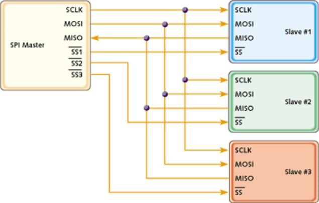
Figure 7.1 An SPI network using several slaves
Comparison to RS-232
SPI is also simpler in design compared to RS-232 communications; RS-232 uses two wires (Tx and Rx), but it requires a set clock speed on both sides of communication. The clock on both devices connected via RS-232 need to be in agreement, preventing configuration problems or desynchronization. SPI masters generate their own clock signal and send that signal to every device. SPI devices are therefore normally simpler to design, cheaper to fabricate, and easier to use.
Another difference between SPI and RS-232 is the way data is sent. RS-232 was designed for long distance communications; SPI is not. It does not need to handle signal noise like RS-232 and therefore does not require checksum bits. This has one major advantage; where RS-232 communications have to send 7-bit or 8-bit data, SPI can select any length it wants. Some devices send 8-bit data, some send 16-bits, even devices using nonstandard lengths like 12-bits can be found on the market.
Configuration
Although SPI does not require explicit configuration like RS-232 devices, it does require a form of configuration. The clock signal is a digital signal, oscillating between a logical one and a logical zero. Some devices will be active on a rising edge (as the clock goes from low to high), and some will be active on a falling edge (as the clock goes from high to low). Also, the clock can be configured to be active low or active high.
Also, because SPI are serial devices, bits are sent one at a time. Because of this, you have to know if the device is expecting the most-significant bit first or the least-significant bit first. Data is normally shifted out with the most significant bit first.
One last configuration is the clock speed. The clock is generated by the master, and as such, it is the master that defines the speed of the bus. Most components have a maximum speed configuration; creating a clock signal above this frequency results in corrupted data.
Communications
SPI is a master/slave protocol, and as such, the master initiates communication with a slave. To do this, it pulls the slave's SS pin low (while maintaining any other SS wires high). This tells the slave that it is being addressed.
To communicate, the slave requires a clock signal, which will be generated by the master. Each clock pulse results in a bit of data being transmitted; however, some sensors (like the DHT-11 used later in this book) require a small timeframe in which the conversion will be made. If this is required, the master must not initiate the clock until the slave has had time to complete the conversion.
When the clock signal is generated, both the master and slave are free to communicate at the same time. In reality both devices do communicate at the same time; the master transmits on the MOSI line, and the slave listens to that line. At the same time, the slave transmits on the MISO line, and the master listens to that line. Both happen at the same time, but some devices do not require meaningful data to be received; a slave device that transmits only data receive data from the master but it ignores all information sent to it.
When the master finishes, either sending the data it requires or retrieving data, it normally stops the clock signal and deselects the slave.
Arduino SPI
The SPI bus on the Arduino is an exception compared to most other ports. On select Arduinos, the SPI bus is present as a dedicated header—the ICSP header, as shown in Figure 7.2.
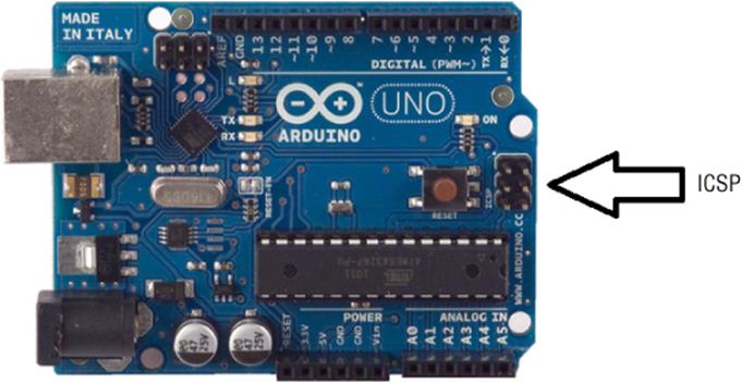
Figure 7.2 The ICSP header on an Arduino Uno
The ISCP header has several uses, including bypassing the Arduino bootloader to program the microcontroller directly, (ISCP is short for In-Circuit Serial Programming), but this is out of the scope of this book.
The ISCP port also normally exposes the SPI bus, depending on models. The Arduino Uno, the reference model of the Arduino family, uses pin 11 and ICSP-4 for the SPI MOSI signal. These pins are duplicates; they are electrically connected. On the Arduino Leonardo, the MOSI pin is available only on the ICSP header and cannot be output to any digital pins.
If you move on to designing your own shields, use the ICSP headers. Arduino shields that use SPI cannot function on the Arduino Leonardo if they do not use the ICSP header, and SPI is used for numerous connections (including SD-card readers).
The ICSP header does not include any SS lines; only the MISO, MOSI, and SCLK lines are exposed, together with power and ground connectors. Because the Slave Select pin is not used to transfer data, but used only to tell a slave that it will be addressed, any digital output pin can be used as a Slave Select. This way, you can have an extremely large amount of slaves on your system; however, remember that only one slave can be selected at any time; it is up to you to drive all the outputs high when not talking to a slave.
Arduinos also have the possibility of becoming an SPI slave, and as such, AVR-based Arduinos have an input SS pin. The Arduino SPI library can be only a master, and as such, this pin must be configured as an output. Failure to do so might make the Arduino believe that it is a slave and render the library inoperative. On most Arduinos, this is pin 10, and on the Arduino Mega2560, it is pin 53.
SPI Library
The Arduino SPI library is a powerful library designed to handle SPI communications simply and effectively. Most Arduino boards utilize the SPI library in the exact same way, but there are notable differences if you're using an Arduino Due. Before discussing these extended methods, let's review the standard functions of the library.
To use the library, you must first import it. In the Arduino IDE, either go to the menu, Sketch ![]() Import Library
Import Library ![]() SPI, or add the library manually:
SPI, or add the library manually:
#include <SPI.h>
To initialize the SPI subsystem, you must first use begin().
SPI.begin();
This function automatically sets the SCLK, MOSI, and SS pins to output, pulling SCLK, MOSI LOW, and SS HIGH. It also sets the MISO pin as an input.
To stop the SPI subsystem, call end():
SPI.end();
Ending the SPI subsystem frees up the I/O lines, letting you use them for other uses.
To configure the SPI bus, three functions are available: setBitOrder(), setDataMode(), and setClockDivider().
setBitOrder() controls the way in which bits are sent on a serial line: the least-significant bit (LSB) first or the most significant bit (MSB) first. This function takes one parameter: a constant, either LSBFIRST or MSBFIRST.
SPI.setBitOrder(order);
setDataMode() sets the clock polarity and phase. It takes a single parameter, the “mode,” for the SPI clock to use.
SPI.setDataMode(mode);
The mode parameter is one of four constants: SPI_MODE0, SPI_MODE1, SPI_MODE2, and SPI_MODE3. The difference between these four modes is listed in Table 7.1.
Table 7.1 The Different SPI Clock Modes
|
Mode |
CPOL |
CPHA |
Effect |
|
SPI_MODE0 |
0 |
0 |
Clock base zero, capture on rising, propagation on falling |
|
SPI_MODE1 |
0 |
1 |
Clock base zero, capture on falling, propagation on rising |
|
SPI_MODE2 |
1 |
0 |
Clock base one, capture on falling, propagation on rising |
|
SPI_MODE3 |
1 |
1 |
Clock base one, capture on rising, propagation on falling |
CPOL is short for Clock Polarity and tells the device if the clock is active on a logical 1 or a logical 0. CPHA is short for Clock Phase and tells the device if data should be captured on a rising edge (going from 0 to 1) or a falling edge (going from 1 to 0).
Finally, the clock divider function, setClockDivider(), is used to set the clock frequency in relation to the system clock.
SPI.setClockDivider(divider);
For AVR-based systems like the Arduino Uno, the divider parameter is a numerical value: 2, 4, 8, 16, 32, 64, or 128. These values are available as constants:
· SPI_CLOCK_DIV2
· SPI_CLOCK_DIV4
· SPI_CLOCK_DIV8
· SPI_CLOCK_DIV16
· SPI_CLOCK_DIV32
· SPI_CLOCK_DIV64
· SPI_CLOCK_DIV128
By default, AVR systems using a system clock of 16 MHz use a divider of 4, SPI_CLOCK_DIV4, resulting in an SPI bus frequency of 4 MHz.
NOTE
The Arduino Due has more advanced SPI features that are explained in the section “SPI on the Arduino Due.”
To send and receive data on the SPI bus, use transfer().
result = SPI.transfer(val);
This function takes a byte as a parameter, the byte to send on the SPI bus. It returns a byte, the byte of data received on the SPI bus. transfer()sends and receives only a single byte per call; to receive more data, call this function as many times as needed.
SPI on the Arduino Due
The Arduino Due is not an AVR device but uses Atmel's SAM3X8E: a microcontroller based on ARM's Cortex-ME design. It is a more powerful device and has advanced SPI functionality.
The SPI library is almost the same on AVR devices and ARM-powered devices, but changes slightly. When calling an SPI function, you must also add the SS pin that will be used.
NOTE
The Extended SPI library for the Due is only available on Arduino 1.5 and greater.
Most SPI devices are compatible, but as you have seen previously, there are different modes, and sometimes you will have two SPI devices on your system that use different modes. This can complicate designs greatly, forcing you to reconfigure the SPI controller each time you change peripherals. The Arduino Due has a way around this.
The Arduino Due can use pins 4, 10, and 52 as slave select. These pins must be specified on each call, including the setup with SPI.begin():
void setup(){
// Initialize the bus for a device on pin 4
SPI.begin(4);
// Initialize the bus for a device on pin 10
SPI.begin(10);
// Initialize the bus for a device on pin 52
SPI.begin(52);
}
begin() is written in a different way:
SPI.begin(slaveSelectPin);
It takes one parameter, the slave select pin, to use. So why is this required? This becomes obvious when configuring the SPI bus:
// Set clock divider on pin 4 to 21
SPI.setClockDivider(4, 21);
// Set clock divider on pin 10 to 42
SPI.setClockDivider(10, 42);
// Set clock divider on pin 52 to 84
SPI.setClockDivider(52, 84);
Each SS pin can have its own clock frequency, and the Arduino automatically changes the clock frequency when talking to a particular slave. This also applies to any configuration made:
// Set mode on pin 4 to MODE0
SPI.setDataMode(4, SPI_MODE0);
// Set mode on pin 10 to MODE2
SPI.setDataMode(10, SPI_MODE2);
The SPI system now automatically changes modes when talking to a particular slave. To initiate communications, use transfer(), specifying the pin:
result = SPI.transfer(slaveSelectPin, val);
result = SPI.transfer(slaveSelectPin, val, transferMode);
Again, it takes a byte, val, and sends it on the SPI bus. It returns result as a byte. However, you must also indicate the slaveSelectPin. This function has an optional parameter, transferMode. Because the extended SPI library requires you to specify the slave select pin, the library will change the outputs of the slave select pin. By specifying the SS pin, this output is pulled low to access the selected slave. By default, when a byte has been sent, the extended SPI library will then output a logical one to the SS pin, deselecting the slave. To avoid this, use the transferMode parameter. This parameter is one of two possible values, as shown in Table 7.2.
Table 7.2 The Transfer Modes Available on the Arduino Due
|
Transfer Mode |
Result |
|
SPI_CONTINUE |
The SS pin is not driven high; it remains low. The slave is still selected. |
|
SPI_LAST |
Specifies that this is the last byte to send/receive. The SS pin is driven high; the slave is deselected. |
By default, SPI_LAST is used. Please be aware that some SPI devices automatically send data when they are selected; deselecting and reselecting the slave after every byte can result in unexpected data.
To stop the SPI interface for a particular pin, use end():
SPI.end(slaveSelectPin);
This terminates the SPI interface for this particular slave select pin, freeing the pin for other uses, but keeps the SPI interface active if other slave select pins were configured.
Example Program
For this application, you create a digital thermometer using a thermocouple. A thermocouple is a temperature measuring device created by the contact of two different conductors: differences in temperature from different points creates voltage. The voltage generated is extremely small (often a few microvolts per degree Celsius) so they are often coupled with amplifiers.
The major advantage to thermocouples is their price—just a few dollars per cable. Their downside is their accuracy; they can sometimes be off by a few degrees (type K typically has a +/–2° C to +/–6° C accuracy), but their temperature range more than makes up for this. A typical thermocouple can work with temperatures between –200° C and +1000° C (–238° F to +1800° F). Although it is not likely that such a device would be used in medical applications, they are frequently used in the industry to monitor temperatures in ovens. To illustrate the temperatures that thermocouples can support, copper becomes liquid at 1084° C (1983° F) and gold becomes liquid at 1063° C (1946° F). They can therefore be placed in almost every oven, fire or barbecue. If ever you want to create a smokehouse to make smoked salmon, a thermocouple is an excellent way to keep track of the temperature directly inside the fire and on the racks.
Thermocouples do not report a temperature; rather, they report a temperature difference between their hot junction (the tip) and the cold junction (the other end of the thermocouple that is connected to the printed circuit board). To use a thermocouple effectively, it is important to know the temperature on the cold junction, and integrated drivers do this automatically.
The MAX31855 is a thermocouple driver, capable of working with a variety of thermocouples. It has good accuracy, fast conversion, and excellent range. (This device, coupled with a type K thermocouple, can register up to +1350° C (+2462° F). Different thermocouples exist, using different metals and handling different temperature ranges. A thermocouple driver must be connected to the correct thermocouple to function. To communicate this data with another device, the MAX31855 uses the SPI bus and is a read-only device. It outputs the thermocouple temperature, reference junction temperature, and fault indicators. The MAX31855 can warn when a thermocouple short occurs, or when the connection is broken, making it excellent for industrial applications.
The MAX31855 is only available in a surface-mounted format (SO-8), but Adafruit has created a small, reliable breakout board for this component. The MAX31855 itself can support only 3.3 V power, but Adafruit have added voltage shifting onto its breakout board, allowing this component to be used by both AVR (which typically operate at 5 V) and the Cortex-M (running at 3.3 V) based Arduinos.
Hardware
For this example, you use an Arduino Due. The Due is a powerful device, powered by 3.3 V and with advanced SPI functionality. You also use an Adafruit MAX31855 breakout board and thermocouple. This board has two connectors: One is placed on the breadboard and the thermocouple connects to one. It requires some soldering; the connectors are packaged with the card but not connected, but it is easy to do and requires only a few minutes.
The Arduino Due has three slave select pins available; for this example, you use the digital pin 10. The layout is shown in the Figure 7.3.
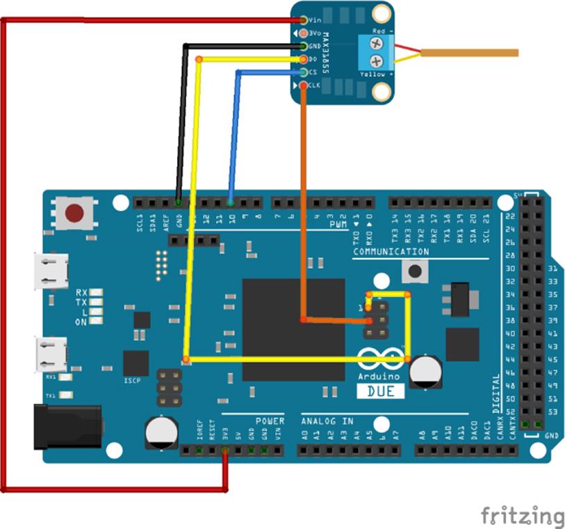
Figure 7.3 Hardware layout image created with Fritzing
The layout is extremely simple; the breakout board is connected to the Arduino Due's 3.3 V power and also to the ground. The driver's SS pin is connected to digital pin 10; this is the slave select pin and will be pulled low when the Arduino Due requests information from the MAX31855. The SPI clock on pin 21 is connected to the breakout board's clock connector. To read information from the breakout board, the MISO, pin 74, is connected to the breakout board's data pin (labeled DO). What about the Arduino Due's MOSI, Master Out-Slave In? The MAX31855 is a read-only device, and as such, does not require any data from the master. To simplify the design, this pin was voluntarily omitted. So how does the MAX31855 know when to send information? This device automatically prepares to send data when its slave select pin is driven low. Temperature conversions and fault detection are done continuously when the MAX31855 is not selected, and as soon as the MAX31855 is selected via slave select (as soon as SS is driven low), the conversion process stops, and it begins to transmit data.
The K-type thermocouple is connected to the breakout board, but be careful of the polarity. The Adafruit thermocouple cable and breakout board come with complete documentation on how to connect. Only the tip should be used to sense the temperature. If the cable is too long, do not put more than necessary inside the device you want to get a temperature reading from. Leave the rest of the cable outside.
There are several versions of the MAX31855 chip: one per cable type. The chip on Adafruit's breakout board can use only K-type thermocouples. Connect the wire to the breakout board, being careful to use the correct polarity (red and yellow wires).
Sketch
Now that the hardware is connected, it is time to deal with the software. This sketch communicates with the MAX31855 through the SPI bus. The datasheets explain how the data transmits. The MAX31855 sends 32-bits of data (unless stopped by the slave select pin), corresponding to several pieces of information. The transmission is shown in Table 7.3.
Table 7.3 MAX31855 Data Output
|
Bit |
Name |
Function |
|
D[31:18] |
14-bit thermocouple temperature data |
Contains signed 14-bit thermocouple temperature |
|
D17 |
Reserved |
Always reads as 0 |
|
D16 |
Fault |
Reads as 1 if a fault is detected, otherwise 0 |
|
D[15:4] |
12-bit internal temperature data |
Contains signed 12-bit cold junction temperature |
|
D3 |
Reserved |
Always reads as 0 |
|
D2 |
SCV Fault |
Reads 1 if the thermocouple is shorted to VCC |
|
D1 |
SCG Fault |
Reads 1 if the thermocouple is shorted to ground |
|
D0 |
OC Fault |
Reads 1 if the thermocouple is not connected |
The data is delivered in a 32-bit package, but there is something interesting about the layout. It can be seen as two 16-bit values: bits D31 to D16 and D15 to D0. The first 16-bits contains everything that is essential: the temperature detected on the thermocouple and a fault bit. If there is a fault, or if the user wants to know the cold-junction temperature, then the second 16-bit value can be read, but otherwise, it is not required.
Time to write the sketch as follows in Listing 7.1:
Listing 7.1: Digital Thermometer Sketch (filename: Chapter7.ino)
1 #include <SPI.h>
2
3 const int slaveSelectPin = 10;
4
5 void setup()
6 {
7 Serial.begin(9600);
8
9 // Initialize the bus for a device on pin 10
10 SPI.begin(slaveSelectPin);
11 }
12
13 void loop()
14 {
15 // Read in 4 bytes of data
16 byte data1 = SPI.transfer(slaveSelectPin, 0, SPI_CONTINUE);
17 byte data2 = SPI.transfer(slaveSelectPin, 0, SPI_CONTINUE);
18 byte data3 = SPI.transfer(slaveSelectPin, 0, SPI_CONTINUE);
19 byte data4 = SPI.transfer(slaveSelectPin, 0, SPI_LAST); // Stop
20
21 // Create two 16-bit variables
22 word temp1 = word(data1, data2);
23 word temp2 = word(data3, data4);
24
25 // Is the reading negative?
26 bool neg = false;
27 if (temp1 & 0x8000)
28 {
29 neg = true;
30 }
31
32 // Is the MAX31855 reporting an error?
33 if (temp1 & 0x1)
34 {
35 Serial.println("Thermocouple error!");
36 if (temp2 & 0x1)
37 Serial.println("Open circuit");
38 if (temp2 & 0x2)
39 Serial.println("VCC Short");
40 if (temp2 & 0x4)
41 Serial.println("GND short");
42 }
43
44 // Keep only the bits that interest us
45 temp1 &= 0x7FFC;
46
47 // Shift the data
48 temp1 >>= 2;
49
50 // Create a celcius variable, the value of the thermocouple temp
51 double celsius = temp1;
52
53 // The thermocouple returns values in 0.25 degrees celsius
54 celsius *= 0.25;
55 if (neg == true)
56 celsius *= -1;
57
58 // Now print out the data
59 Serial.print("Temperature: ");
60 Serial.print(celsius);
61 Serial.println();
62
63 // Sleep for two seconds
64 delay(2000);
65 }
On the first line, the SPI library is imported. Because this is an Arduino Due, version 1.5 or later of the Arduino software must be used. On line 3, a constant is declared, naming the pin that will be used by the Slave Select. The sketch needs this information. Because you will be using the extended library, the Arduino will activate the slave select pin; you won't have to.
On line 5, setup()is declared. The serial output is configured on line 7, and on line 10, the SPI subsystem is initialized for the one slave select pin declared as a constant earlier: slaveSelectPin.
On line 13, loop()is declared. This will contain all the SPI routines and print the temperature. On line 16, an SPI read function is called. By calling an SPI read with the slaveSelectPin variable, the Arduino Due automatically pulls the slave select pin low. For the MAX31855, this has the effect of initiating communication; the MAX31855 will wait for a valid clock to write 32 bits of data to the master. By using the SPI_CONTINUE variable, the slave select pin is maintained low. Because you want to read 32 bits of data, and because the transfer()function sends and receives 8 bits, this must be done four times. The first three are called with the SPI_CONTINUE parameter, but the fourth is called with the SPI_LAST parameter on line 19, indicating that this is the last transfer, and the Arduino should pull the slave select pin high. This is all done automatically.
The four calls have been made by sending the value zero. Because the MAX31855 is not connected to the MOSI pin, you can send any data you want; it will simply be ignored.
The data is now contained in four bytes. The first temperature reading is 14-bits, so it is now contained in 2 bytes, but how can that be used? The creators of the MAX31855 have put a lot of thought into the data output, and the data can be separated into two 16-bit values, or two “words.” To create a word from 2 bytes, you can use word(). This function takes 2 variables in the form of 2 bytes, and concatenates them into a word, a 16-bit value. This is done on line 22 and 23.
On line 26, a boolean is declared. According to the datasheet, bit 31 corresponds to the sign of the temperature. This will be read now; the data will be transformed later. On line 27, a logical AND is made, comparing the value to 0x8000; which is the bitmask, used to access a specific byte in the data (refer to the discussion of “Reading and Writing Bits” in Chapter 6 for more information on bitmasks). If the value is true, then the first bit is equal to one, meaning that the temperature reading is negative, and the neg variable is updated.
Bit number 16 corresponds to a fault condition; if it is true, then the MAX31855 is reporting an error and a bitwise comparison is made on the second 16-bit value where bits 0, 1, and 2 correspond to specific faults.
On line 45, a bitmask is created. The first 16 bits of data correspond to the temperature, but you will not need all that information. By creating a bitmask, you can filter out bits that do not interest you. In this case, the first bit, the sign, isn't required; it has already been placed in a variable. The last two are also of no interest and are discarded. The data is still not usable in its current state; the last 2 bits have been discarded and are equal to zero, but now the data has to be “shifted”; pushing the bits right until they are aligned as required.
On line 51, a new variable is created, a double. On the Due, this type of variable can contain floating point values with 64 bits of precision. Because the MAX31855 returns values in increments of 0.25 degrees, using a double or a float ensures that the decimal values are kept. First, the shifted 16-bit value is copied into this variable, and then it is multiplied by 0.25; it now contains the correct temperature in degrees Celsius.
Finally, the temperature might be negative. This is checked on line 55; if the neg variable is true, then the value returned was negative, and so the temperature is multiplied by –1.
On line 59, this temperature is written to the serial port, and the Arduino is told to wait for 2 seconds. The MAX31855 continues to monitor the temperature and continues to convert that temperature. When SPI.transfer() is next called through loop(), the MAX31855 communicates the temperature to the Arduino without the need for waiting.
Exercises
This sketch displays the temperature in degrees Celsius but not in Fahrenheit. Try to add a function to convert between Celsius and Fahrenheit. The conversion is a simple mathematical formula; multiply the temperature in Celsius by 1.8, and then add 32.
The MAX31855 is designed so that the first 16 bits correspond to the temperature with an additional fault bit. The last 16 bits are not normally required for normal operations; how would you modify the sketch to read the next 16 bits only if a fault is detected.
This sketch is designed to work with an Arduino Due, but you can modify it to be used on an Arduino Uno. Try to make this work on an Arduino Uno by using standard SPI commands.
Summary
In this chapter, you have seen how to communicate with sensors using the SPI bus, and you have created your first sensor board. In the next chapter, you will see another serial communications protocol commonly used on Arduino projects: the I2C protocol.
All materials on the site are licensed Creative Commons Attribution-Sharealike 3.0 Unported CC BY-SA 3.0 & GNU Free Documentation License (GFDL)
If you are the copyright holder of any material contained on our site and intend to remove it, please contact our site administrator for approval.
© 2016-2026 All site design rights belong to S.Y.A.