Arduino Sketches: Tools and Techniques for Programming Wizardry (2015)
Part II. Standard Libraries
Chapter 8. Wire
This chapter discusses the following functions:
· begin()
· beginTransmission()
· write()
· endTransmission()
· read()
· available()
· requestFrom()
· onReceive()
· onRequest()
The hardware needed to use the examples in this chapter includes:
· Arduino Uno x 2
· Arduino Due
· Silicon Labs Sensor EXP board
You can find the code downloads for this chapter at http://www.wiley.com/go/arduinosketches on the Download Code tab. The code is in the Chapter 8 folder and individually named according to the code filenames noted throughout this chapter.
Introducing Wire
Connection wires I2C, short for Inter-IC bus, is a serial bus designed to enable access to numerous devices. The Arduino's hardware serial bus can connect only to one device at a time, and SPI (see Chapter 7) can talk to three devices. In 1982, Philips created the I2C standard, capable of addressing hundreds of devices, using only two wires. It was first used to connect peripherals together in a television set, but since then, I2C has been used in cars, computer systems, and hobbyist electronics, to name a few. It is an easy and inexpensive way to interconnect dozens (if not hundreds) of devices on a same network.
Originally, only a few I2C devices existed, but today there are hundreds of devices. Temperature sensors, pressure sensors, accelerometers, displays, and even EEPROM memory can all be accessed by I2C, using simple reads and writes. An EEPOM device controlled by I2C is illustrated in Figure 8.1.
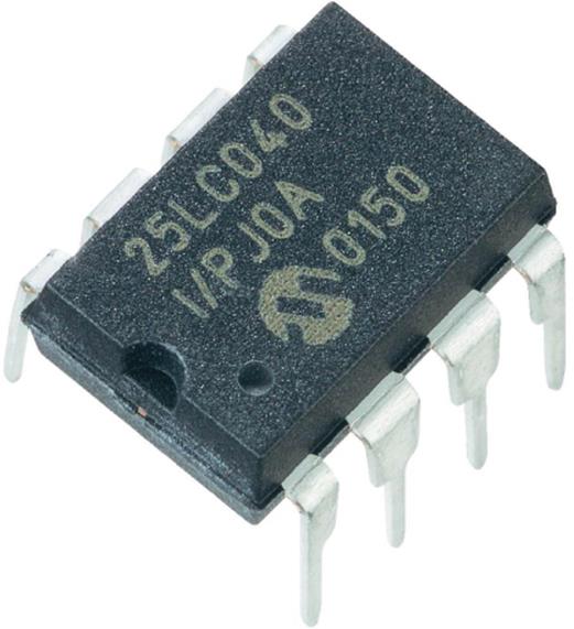
Figure 8.1 I2C EEPROM integrated circuit
I2C is based on a master slave system; the master addresses slaves and requests information. The slave then replies and remains silent until again asked to communicate by the master. The original IsC specification allowed communications up to 100 kHz but numerous specifications existed. The newest in 2012 allows for 5 MHz clock speeds.
Another name for I2C is the Two Wire Interface (shortened to TWI). This is where the Wire library gets its name.
Connecting I2C
I2C requires two data wires, as well as a common ground. The two wires are called SDA (for Serial Data), and SCL (for Serial Clock). All devices in the I2C network are connected to these two wires. Both SDA and SCL lines are open drain, meaning that the devices can force their value low but cannot provide power, which will be provided directly from the main power line. For I2C to work, these two lines must be equipped with pull-up resistors, as shown in Figure 8.2. The values are not critical, and values range widely; 4.7 kilohm resistors are common. Arduinos have internal pull-up resistors that are automatically activated on both the SDA and SCL lines when the I2C connection is initialized. This is illustrated in Figure 8.2.
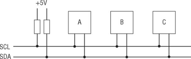
Figure 8.2 Pull-up resistors to SDA and SCL lines
Connecting multiple I2C devices is extremely easy; there is no notion of chip select, chip activate, or any other mechanism. All SDA pins are connected together, and all SCL pins are also connected together. The I2C protocol defines which circuit is to respond.
I2C Protocol
I2C is a master/slave network; the master initiates the communication, and the slave responds. Each I2C slave has a specific address, and the master must send this address to the network for a slave to answer. The I2C protocol has several specifications, so care must be taken when choosing devices, as there is a lot of confusion concerning addressing.
Address
The original I2C protocol specified 7-bit addressing and was later extended to allow 10-bit addressing. Some vendors talk about 8-bit addressing, but technically, this does not exist. Here's why.
I2C can send and receive data only in multiples of 8 bits—8 bits, 16 bits, and so on. In 7-bit addressing, addresses are (of course) 7 bits long, and the last bit is used to select a read or a write, for a total of 8 bits. In 10-bit addressing, things are a little more complicated. There is still the R/W bit, but the first 5 bits are sent as 11110, an address that is reserved in 7-bit addressing and is used only to tell the system that another byte will follow with the address complement. Figure 8.3 shows both 7-bit and 10-bit addressing.
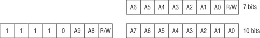
Figure 8.3 7-bit and 10-bit addressing methods
Some vendors give 8-bit addresses for devices, but again, technically, they do not exist. Vendors will give two values for 8-bit devices, both a read and a write address. The first 7 bits will be the same, but the last bit will be 1 for a read operation or 0 for a write operation. An example of this is shown in Figure 8.4.
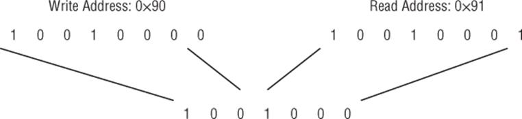
Figure 8.4 8-bit addresses
When the master contacts a slave on the I2C network, it sends two vital pieces of information; the address of the slave, and whether it is a read or write operation. When this information is received by the slaves, each slave compares the address to its own. If a device has this address, it will send an acknowledge signal (referred to as ACK), indicating that it is present on the network and that the master can now issue instructions.
I2C devices tend to be small with few pins. (Most devices have the bare minimum.) Therefore, it is rarely possible to configure your own addresses for these devices. Most devices therefore have addresses that are specified by the manufacturer. On an ordinary computer network, it is easy to have dozens of the same type of computer with a user settable IP address unique to each machine. On an I2C network, this isn't possible; two identical sensors will use the same address. To allow developers to have several sensors in the same network, some devices allow you to change the address depending on input pins. By connecting one or several pins to either +5 V or 0 V, you can set part of the address (usually the lower bits). You might therefore have several temperature sensors, using addresses 0x90, 0x91, and 0x92, as shown in Figure 8.5.
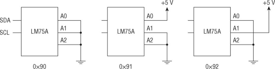
Figure 8.5 Configuring different addresses
Communication
I2C works on the master/slave scheme; a master either requests information from a slave or gives information to a slave. The master is responsible for initiating contact before releasing the bus so that a slave may communicate. Slaves cannot “talk” without permission; a slave cannot warn the system of an action; the master must poll for this information. This is the big difference between I2C and standard serial communication; it is not full duplex, meaning that devices cannot send data and receive data at the same time. Only one master is on an I2C network (except for some specific configurations).
To talk to devices, I2C uses a system of registers. A register is a small memory location on each device that can store data; it can be read or written to (sometimes both) depending on the type of data that is contained. For example, a temperature sensor has a register that contains the current temperature. When a master asks for information, it does not ask directly for the temperature; instead, it asks for the contents of a register. A temperature sensor will, of course, have a temperature register but might contain a configuration register (Celsius or Fahrenheit), a warning register (when this temperature is reached, an external interrupt occurs), and possibly others with different specialized functions. To read or write this data, you need to know several details:
· The slave address
· The register number
· If it is a read or write operation
· The length of the data to be received
It is important to know exactly how much data is to be sent and received. Each I2C device is different and will function in a different way. Devices that have only one writable register might accept a single byte of data directly and will place that byte into the register. Other devices with several writable registers might require you to send the register number, followed by the contents, or maybe send the contents of all the registers in multiple writes. I2C describes a way to send data and receive data, but for your own implementation, it is up to you what you need.
All Arduinos have a pair of I2C pins. The Arduino Due has two separate I2C buses, SDA and SCL, as well as SDA1 and SCL1. The pins reserved for I2C operations are listed in Table 8.1.
Table 8.1 I2C Pins on Different Arduino Boards
|
Board |
SDA |
SCL |
|
Uno |
A4 |
A5 |
|
Ethernet |
A4 |
A5 |
|
Mega2560 |
20 |
21 |
|
Leonardo |
2 |
3 |
|
Due |
20 |
21 |
Communicating
To communicate on the I2C bus, the Wire library must first be initialized. As with all Arduino libraries, you must import the Wire library. This is done by either adding the library from the Arduino IDE (Sketch ![]() Import Library
Import Library ![]() Wire) or by manually typing in the sketch.
Wire) or by manually typing in the sketch.
#include <Wire.h>
To declare the Arduino as an I2C device, call Wire.begin(). If the Arduino is used as a slave, you must specify an address.
Wire.begin(address); // configures the Arduino as an I2C slave
Masters do not have an address because they are free to start communications whenever they want and automatically receive all responses. To declare the Arduino as a master, call the Wire.begin()command, without an address parameter.
Wire.begin(); // configure the Arduino as an I2C master
Master Communications
On most projects, the Arduino is configured as an I2C master, sending messages to slaves and listening to the responses. To create an I2C message, you must follow several steps:
1. Begin the transmission.
2. Write the data.
3. End the transmission.
This creates a custom I2C message to a specific slave. When a slave answers, there is no encapsulation, and a write can be performed without beginning or ending a transmission. Data requests are also encapsulated but are made by a single function.
Sending Information
The I2C protocol specifies that master communication must be done in a single transmission. To avoid breaks in the message, the message is first constructed and completed before being sent.
To start sending data, the sketch must first begin a transmission structure by using Wire.beginTransmission(). It takes one parameter, the destination address.
Wire.beginTransmission(address);
The sketch is then required to queue data, using Wire.write(). This function can be called in three different ways. It can be called with a byte as the parameter to be appended to the queue. A string can be specified, in which case each byte of the string will be appended. An array can be specified with a second parameter, the length of data to send. Wire.write() will return the amount of bytes appended to the message, but it's not necessary to read this.
Wire.write(value); // append a byte
Wire.write(string); // append a string
Wire.write(data, length); // append an array with a specified number
of bytes
number =Wire.write(string); // store the number of bytes appended in
a variable
Wire.endTransmission() specifies the end of the message, and sends it. This function takes an optional parameter, the bus release parameter. If TRUE, a stop message is sent, and the I2C bus is freed. If FALSE, a restart message is sent; the I2C bus is not released, and the master can continue issuing orders. By default, the bus is always freed.
Wire.endTransmission(); // send the message
Wire.endTransmission(stop); // send the message and close the connection
Wire.endTransmission() returns a status byte. Table 8.2 shows a list of return values.
Table 8.2 Transmit Error Codes
|
Return Code |
Result |
|
0 |
Success |
|
1 |
Data too long to fit in the transmit buffer |
|
2 |
Receives a NACK on transmit of address |
|
3 |
Receives a NACK on transmit of data |
|
4 |
Unknown error |
Requesting Information
When requesting information, the master performs a read operation, specifying the destination and the number of bytes the slave should send. The entire message is created using a single function: Wire.requestFrom(). This function takes two parameters and an optional third. First, the destination has to be specified—which slave is to receive this message and send data? Second, how much data is the master requesting? This is specified as the number of bytes. Finally, an optional parameter specifies if the bus should be released.
Wire.requestFrom(address, quantity);
Wire.requestFrom(address, quantity, stop);
Wire.requestFrom() creates a message and immediately sends it on the I2C bus. Now that the request has been sent, the master can wait for a message using Wire.read().
data = Wire.read(); // store the information in a variable
Wire.read() returns a single byte from the input buffer. For multibyte messages, this function must be called for each byte. Requesting a certain amount of bytes does not mean that the slave will send that amount of data; it could be less. To see if any data is available in the buffer, call Wire.available().
number = Wire.available();
Wire.available() looks at the buffer and returns the amount of bytes remaining. It can be used with Wire.read() to create a routine that does not block if data is not available.
while(Wire.available()) // Repeat as long as there is data waiting
{
char c = Wire.read(); // Read in one byte
Serial.print(c); // Print the byte
}
Slave Communications
Most people expect the Arduino to be an I2C master, controlling the network. In some cases, it can be useful to have an Arduino as an I2C slave, especially when several Arduinos are to be used. Arduinos also have a major advantage over other I2C devices; you can specify any address you see fit. You can have a total of 128 Arduino slaves on an I2C network, which should be more than enough to fully automate your house.
You do not know when an I2C master will send or request information, and a sketch cannot be told to hold indefinitely while waiting for information. To allow a sketch to continue while waiting for an I2C request, the Wire library allows you to create callbacks, functions that are called when an event occurs. The I2C callbacks are Wire.onReceive() (when the Arduino receives information) and Wire.onRequest() (when the Arduino is requested for information).
Receiving Information
Wire.onReceive() is called when a master sends information to a slave. To create this callback, you must create a function. The name can be anything you choose, but it must accept one parameter, an int (the number of bytes received from the master).
void receiveData(int byteCount)
{
// Put your code here
}
Wire.onReceive(receiveData); // Create the callback
When the Arduino slave receives an I2C communication, the Wire library calls this function with the number of bytes received. To receive individual bytes, call Wire.read().
data = Wire.read();
Just as when communicating as a master device,Wire.read() reads 1 byte from the I2C buffer and returns that data. Similarly, to know the amount of remaining bytes in the I2C buffer, call Wire.available().
number = Wire.available();
It is, of course, possible to mix the two functions together.
while(Wire.available())
{
data = Wire.read();
// Do something with data
}
Sending Information
When a slave Arduino is asked for information, the Wire library calls the function previously registered by Wire.onRequest(). Again, the name of the function can be anything you want, but this one takes no parameters and returns nothing.
void sendData(void)
{
// Put your code here
}
Wire.onRequest(sendData); // Create the callback
You must then provide the data required by the master, using Wire.write(), explained previously.
Example Program
For this example program, you use two Arduinos: one acts as an I2C master, and the second acts as an I2C slave. Both connect together using the I2C bus. Because Arduinos have internal pull-up resistors, the resulting schematic is extremely simple. The SDA pins of both devices are connected together, and the SCL pins are also connected together. There is one last, important stage: Both grounds are also connected—yes, three wires between the two devices. I said that I2C is a two-wire solution, and it is. It was designed to be used inside a single device, where the power supply and ground is normally identical. It can also be used for inter-device communication, like in this project, but in that case, the grounds must be connected.
The slave Arduino will turn on and off the on-board LED according to messages from the master. The master can send “0” to turn the LED off and “1” to turn the LED on. It can also request a byte of data from the slave; this data will be the current state of the LED. The master will also turn its LED on and off, so you should see a perfectly synchronized pair of LEDs.
Time to start, so start with the slave. The code is simple as shown in Listing 8.1.
Listing 8.1: The Slave (filename: Chapter8bSlave.ino).
1 #include <Wire.h>
2
3 #define SLAVE_ADDRESS 0x08
4 int data = 0;
5 int state = 0;
6
7 void setup()
8 {
9 pinMode(13, OUTPUT); // Internal LED
10 Serial.begin(9600);
11 Wire.begin(SLAVE_ADDRESS); // Initialize as I2C slave
12
13 // Register I2C callbacks
14 Wire.onReceive(receiveData);
15 Wire.onRequest(sendData);
16 }
17
18 void loop()
19 {
20 // Nothing to do
21 delay(100);
22 }
23
24 // Callback for data reception
25 void receiveData(int byteCount)
26 {
27 while(Wire.available())
28 {
29 data = Wire.read();
30 Serial.print("Data received: ");
31 Serial.println(data);
32
33 if (data == 1)
34 {
35 digitalWrite(13, HIGH); // Turn the LED on
36 state = 1;
37 }
38 else
39 {
40 digitalWrite(13, LOW); // Turn the LED off
41 state = 0;
42 }
43 }
44 }
45
46 // Callback for sending data
47 void sendData()
48 {
49 Wire.write(state); // Send the LED state
50 }
On line one, the Wire library is imported. On line 3, a value is declared, SLAVE_ADDRESS. This is the slave I2C address, and it will be needed later by the master.
On line 7, setup() is defined. This function contains everything the sketch needs to function correctly. Pin 13 is set as a digital output because this is the pin that has an on-board LED. Serial communication is started, in case you want to debug anything. On line 11, the I2C subsystem is initialized, and because an address is specified (SLAVE_ADDRESS), this board will be an I2C slave. To be an effective I2C slave, the sketch requires at least one of two callbacks to be present; either when receiving or sending data. In this case, both are used.
On line 14, a callback is created to be called when data is received. This callback registers the function receiveData(), declared on line 25. The second callback is used when the slave is asked to provide data. It registers the function sendData(), which is declared on line 25.
Nothing happens in loop(). This sketch responds only to I2C messages, and when the buffer is empty, it is not expected to do any work, so loop() is empty.
On line 25, receiveData() is declared. Thanks to the callback, this function is called every time data is received on the I2C bus destined for this Arduino. It requires one parameter, the number of bytes received as the parameter byteCount. Due to the nature of this project, only 1 byte will be received at a time, so each byte received is immediately handled. On other projects, this can be used to detect the type of transmission.
On line 27, the sketch runs a while loop and continues to iterate so long as data is available in the buffer. The byte is read into the data variable by Wire.read() on line 29. Finally, the LED is turned on if the byte received was equal to 1 and turned off otherwise.
There is a second function, called sendData(), defined on line 47. This function is simple; when a data request is received, it sends out 1 byte, the state of the LED. Because this is an answer, there is no need to create a message; the sketch is free to send a byte directly to the master, as ordered.
Now that the slave is programmed, it is time to create the master sketch. The code is shown in Listing 8.2.
Listing 8.2: Master Sketch (filename: Chapter8bMaster.ino).
1 #include <Wire.h>
2
3 #define SLAVE_ADDRESS 0x08
4 int data = 0;
5 int state = 0;
6
7 void setup()
8 {
9 pinMode(13, OUTPUT); // Internal LED
10 Serial.begin(9600);
11 Wire.begin(); // Initialize as I2C master
12 }
13
14 void loop()
15 {
16 Wire.beginTransmission(SLAVE_ADDRESS); // Prepare message to slave
17 Wire.write(1); // Send one byte, LED ON
18 Wire.endTransmission(); // End message, transmit
19 digitalWrite(13, HIGH); // Turn the LED on
20
21 delay(10); // Give the slave time to react
22 printLight(); // What is the slave's status?
23
24 delay(1000);
25
26 Wire.beginTransmission(SLAVE_ADDRESS); // Prepare message to slave
27 Wire.write(0); // Send one byte, LED OFF
28 Wire.endTransmission(); // End message, transmit
29 digitalWrite(13, LOW); // Turn the LED off
30
31 delay(10); // Give the slave time to react
32 printLight(); // What is the slave's status?
33
34 delay(200);
35 }
36
37 void printLight()
38 {
39 Wire.requestFrom(SLAVE_ADDRESS, 1); // Request 1 byte from slave
40
41 data = Wire.read(); // Receive a byte af data
42 switch (data)
43 {
44 case 0:
45 Serial.println("LED is OFF");
46 break;
47 case 1:
48 Serial.println("LED is ON");
49 break;
50 default:
51 Serial.println("Unknown status detected");
52 break;
53 }
54 }
This sketch starts the same as the slave sketch; the Wire library is imported, and the address of the slave is defined. setup() is almost identical, except on line 11, begin() does not take an address parameter because this is the master.
Unlike the slave sketch, the master sketch uses loop(). It is designed to tell the slave to turn on its LED, wait for a few milliseconds, and then tell the slave to turn off its LED. After each transmission, it requests a byte of information to know the current state of the LED.
On line 16, the sketch begins creating a message. Wire.beginTransmission() requires one parameter, the destination address, which in this case is the slave Arduino. A message is created in a buffer but not sent. The Arduino automatically formats the message as required. On line 17, a byte is added to the message—a simple value: 1. According to the project specifications, sending a 1 to the slave turns on the LED. The instruction is added, but the message is not complete. Another step is required: Wire.endTransmission(). On line 18, that is exactly what is done. By using default settings, the message is sent and the I2C bus is freed.
To illustrate what is going on, the master also turns its LED on and off. This is what is done on line 19. On line 22, printLight() is called. This function is declared on line 37. It requests a byte from the slave, and prints the result in readable format.
To request data from a slave, Wire.requestFrom() is called. This is done on line 39. The first parameter is the address; in this case, the slave. The second parameter is the number of bytes to return—in this case: a single byte. When the order is sent, the sketch waits for a read() operation to complete, on line 41. That data is then fed into a switch statement, and the data is printed to the serial line.
When the sketch finishes turning the slave's LED on, the entire process is repeated with an order to turn the LED off.
Exercises
This sketch can control one LED by sending 1 byte, telling the slave to either turn the LED on or off. By sending 2 bytes, you could tell the slave to turn on one of several LEDs. Try to modify this sketch to turn on several LEDs. Remember that the I2C protocol can send bytes and request bytes. It is up to you to decide how to inform the slave of your intentions. What solution did you come up with?
Traps and Pitfalls
The I2C protocol is rather complex, and as such, problems can arise. They are normally easily fixed, and most electronic components use the standard I2C revision, simplifying usage.
Voltage Difference
Most Arduinos are powered by 5 volts, but some I2C circuits can be powered by 3.3 V, sometimes even lower. If you need to use 3.3-V devices (like the example in this chapter), then you have three choices. You could use a 3.3-V device like the Arduino Due. This was the solution chosen for this chapter. You could also use a level shifter, an electronic component that can convert a 3.3-V signal to a 5-V signal. The third option is to use a 5-V device anyway, but there are risks.
The I2C is an open drain bus, meaning that power is not supplied by the components, but rather by the power lines themselves using pull-up resistors. The Arduino's I2C pins have internal pull-up resistors that are automatically activated, pulling the line to 5 V. If you include external pull-up resistors to a 3.3-V power rail (like the one supplied by an Arduino), then the end result will be a voltage level slightly above 3.3 V. Most devices can handle up to 3.6 V without a problem.
The input voltage is also a problem. The Atmel AVR specifications say that an I2C input is considered high when it reaches and surpasses 0.7 times the power voltage. For a 5-volt system, this means the signal must reach 3.5 volts. With two external pull-up resistors to a 3.3-V rail, this is achieved, but there is little margin for error. It could work, and in practically all cases, it does, but be aware of the technical implications. I have never heard of either an I2C device or an Arduino being damaged by this technique, but if you are making a long-term project or a professional board, you might want to consider using other techniques.
Bus Speed
Numerous bus frequencies exist for I2C; the original bus speed was 100 kHz, but additions allowed 400 kHz, 1 MHz, 3.4 MHz, and 5 MHz speeds. Components using the Ultra Fast Mode transfer speed (5 MHz) are rare and heavily specialized. Most standard components use the 100 kHz bus speed. Be aware that you cannot mix bus speeds; all components use the same bus speed as defined by the master. Arduinos are programmed to use a 100 kHz clock speed. It is possible to change this speed, but it involves editing the source code of the Arduino programming environment, which is out of the scope of this book. For standard Arduino applications, the bus is limited to 100 kHz, which is sufficient for most sensors.
Shields with I2C
Some shields require the presence of I2C, but this is a problem for some boards. If you use an Arduino Uno, the I2C pins are A4 and A5. However, on the Arduino Mega 2560, I2C is on pins 20 and 21, so shields requiring I2C that work on the Uno will not work on the Mega 2560. Be careful if using a shield with I2C.
Summary
In this chapter, you have seen how to connect I2C devices, and how to communicate with them. You have also seen how the Arduino can become an I2C master, and how to configure it to become an I2C slave.
In the next chapter, you will consider the Ethernet protocol and how it is used to network computers together. I will show you how to connect your Arduino to a local network, how to configure the board, and how to communicate both as a client and as a server.
All materials on the site are licensed Creative Commons Attribution-Sharealike 3.0 Unported CC BY-SA 3.0 & GNU Free Documentation License (GFDL)
If you are the copyright holder of any material contained on our site and intend to remove it, please contact our site administrator for approval.
© 2016-2026 All site design rights belong to S.Y.A.