Getting Started with Windows Remote Arduino (2015)
5. Working with I2C
In this chapter we learn how to work with I2C using Windows Remote Arduino.
5.1 Getting Started
The I2C (Inter-Integrated Circuit) bus was designed by Philips in the early '80s to allow easy communication between components which reside on the same circuit board. TWI stands for Two Wire Interface and for most marts this bus is identical to I²C. The name TWI was introduced by Atmel and other companies to avoid conflicts with trademark issues related to I²C.
I2C bus consists of two wires, SDA (Serial Data Line) and SCL (Serial Clock Line). Arduino Uno has I2C/TWI on Analog A4 (SDA) and Analog A5 (SCL).
For testing, I used PCF8591 AD/DA Converter module with sensor and actuator devices. You can find it on the following online store:
· Amazon, http://www.amazon.com/PCF8591-Converter-Module-Digital-Conversion/dp/B00BXX4UWC/
· eBay, http://www.ebay.com
· Dealextreme, http://www.dx.com/p/pcf8591-ad-da-analog-to-digital-digital-to-analog-converter-module-w-dupont-cable-deep-blue-336384
· Aliexpress, http://www.aliexpress.com/
In addition, you can find this device on your local electronics store/online store.
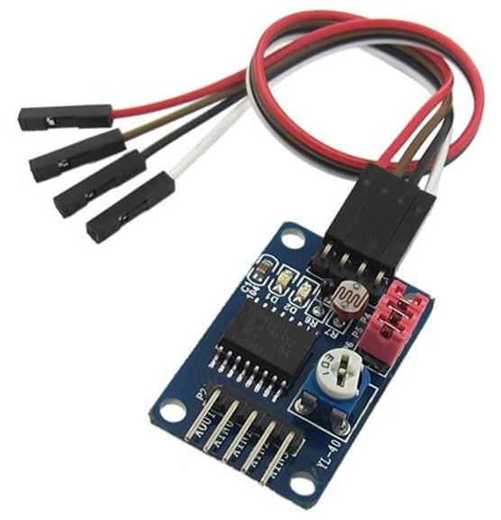
This module has mini form model too, for instance, you can find it on Amazon, http://www.amazon.com/WaveShare-PCF8591T-Converter-Evaluation-Development/dp/B00KM6X2OI/ .
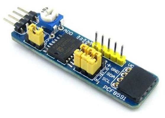
This module use PCF8591 IC and you can read the datasheet on the following URLs.
· http://www.electrodragon.com/w/images/e/ed/PCF8591.pdf
· http://www.nxp.com/documents/data_sheet/PCF8591.pdf
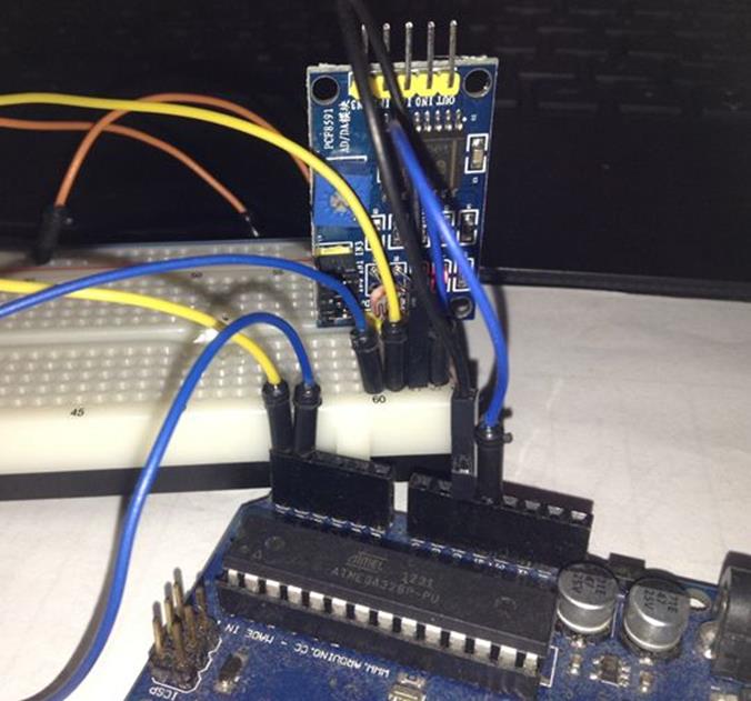
The following is our wiring lab:
· PCF8591 AD/DA SDA --> Arduino Analog A4 (SDA)
· PCF8591 AD/DA SCL --> Arduino Analog A5 (SCL)
· PCF8591 AD/DA GND --> Arduino GND
· PCF8591 AD/DA VCC --> Arduino VCC +3.3V
Hardware implementation can be shown in Figure below.
5.2 Writing Program
Firstly, create a new project, called I2CDemo. Follow instructions to create and configure the project as explained on section 2.3.2, 2.3.3 and 2.3.4.
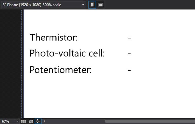
The first step is to develop app UI on MainPage.xaml. We add six TextBlock to display Analog values. The following is complete code for MainPage.xaml file.
<Page
x:Class="I2CDemo.MainPage"
xmlns="http://schemas.microsoft.com/winfx/2006/xaml/presentation"
xmlns:x="http://schemas.microsoft.com/winfx/2006/xaml"
xmlns:local="using:I2CDemo"
xmlns:d="http://schemas.microsoft.com/expression/blend/2008"
xmlns:mc="http://schemas.openxmlformats.org/markup-compatibility/2006"
mc:Ignorable="d">
<Grid Background="{ThemeResource ApplicationPageBackgroundThemeBrush}">
<TextBlock x:Name="textBlock" HorizontalAlignment="Left" Margin="10,52,0,0" TextWrapping="Wrap" Text="Thermistor:" VerticalAlignment="Top"/>
<TextBlock x:Name="textBlock1" HorizontalAlignment="Left" Margin="10,77,0,0" TextWrapping="Wrap" Text="Photo-voltaic cell:" VerticalAlignment="Top"/>
<TextBlock x:Name="textBlock2" HorizontalAlignment="Left" Margin="10,102,0,0" TextWrapping="Wrap" Text="Potentiometer:" VerticalAlignment="Top"RenderTransformOrigin="-1.593,-0.469"/>
<TextBlock x:Name="txtThermistor" HorizontalAlignment="Left" Margin="163,52,0,0" TextWrapping="Wrap" Text="-" VerticalAlignment="Top"/>
<TextBlock x:Name="txtPhoto" HorizontalAlignment="Left" Margin="163,77,0,0" TextWrapping="Wrap" Text="-" VerticalAlignment="Top"/>
<TextBlock x:Name="txtPot" HorizontalAlignment="Left" Margin="163,102,0,0" TextWrapping="Wrap" Text="-" VerticalAlignment="Top"/>
</Grid>
</Page>
The next step is to modify MainPage.xaml.cs file. Firstly, we add our namespace.
using System.Text;
using Windows.ApplicationModel.Core;
using Microsoft.Maker.Serial;
using Microsoft.Maker.RemoteWiring;
Declare some variables. PCF8591 uses I2C address on 0x90. To get Thermistor value, we send a command 0x40. Photo-voltaic value can be acquired by sending a command 0x41. The last, Potentiometer, can be acquired using 0x43 command.
private UsbSerial connection;
private RemoteDevice arduino;
private const byte NUM_DIGITAL_PINS = 14; // Arduino Uno
private const byte SDA = 4;
private const byte SCL = 5;
private const byte PCF8591 = (0x90 >> 1); // Device address
private const byte PCF8591_ADC_CH0 = 0x40; // thermistor
private const byte PCF8591_ADC_CH1 = 0x41; // photo-voltaic cell
private const byte PCF8591_ADC_CH2 = 0x42;
private const byte PCF8591_ADC_CH3 = 0x43; // potentiometer
private int index = 0;
private Queue<int> i2cReading = new Queue<int>();
private DispatcherTimer timer;
We define InitWRA() method and subscribe ConnectionEstablished event. On this event, we subscribe I2cReplyEvent event. On I2cReplyEvent event, we update TextBlock UI. Because we update UI from other thread, we use Dispatcher.RunAsync(). We define UpdateDate().
private void InitWRA()
{
connection = new UsbSerial("VID_2341", "PID_0043");
arduino = new RemoteDevice(connection);
connection.ConnectionEstablished += Connection_ConnectionEstablished;
connection.begin(57600, SerialConfig.SERIAL_8N1);
}
private void Connection_ConnectionEstablished()
{
System.Diagnostics.Debug.WriteLine("Connected");
arduino.pinMode(NUM_DIGITAL_PINS + SDA, PinMode.I2C);
arduino.pinMode(NUM_DIGITAL_PINS + SCL, PinMode.I2C);
index = 0;
arduino.I2c.I2cReplyEvent += I2c_I2cReplyEvent;
timer = new DispatcherTimer();
timer.Interval = TimeSpan.FromMilliseconds(2000);
timer.Tick += Timer_Tick;
timer.Start();
}
private void I2c_I2cReplyEvent(byte address_, string response)
{
byte[] data = Encoding.UTF8.GetBytes(response);
int curr = i2cReading.Dequeue();
UpdateData(curr, data[1]);
System.Diagnostics.Debug.WriteLine("" + Convert.ToString(address_) + "-" + curr.ToString() + ": " + BitConverter.ToString(data));
}
On Tick event from Timer object, we read analog values from PCF8591. Then, we define UpdateData() to update app UI.
private void Timer_Tick(object sender, object e)
{
switch (index)
{
case 0:
i2cReading.Enqueue(index);
System.Diagnostics.Debug.WriteLine("PCF8591_ADC_CH0");
ReadADC(PCF8591_ADC_CH0);
break;
case 1:
i2cReading.Enqueue(index);
System.Diagnostics.Debug.WriteLine("PCF8591_ADC_CH1");
ReadADC(PCF8591_ADC_CH1);
break;
case 2:
i2cReading.Enqueue(index);
System.Diagnostics.Debug.WriteLine("PCF8591_ADC_CH2");
ReadADC(PCF8591_ADC_CH2);
break;
}
index++;
if (index > 2)
index = 0;
}
void ReadADC(byte config)
{
arduino.I2c.enable();
arduino.I2c.write(PCF8591, "" + (char)config);
arduino.I2c.read(PCF8591,2);
arduino.I2c.stop(PCF8591);
}
private async void UpdateData(int index, byte value)
{
await CoreApplication.MainView.CoreWindow.Dispatcher.RunAsync(Windows.UI.Core.CoreDispatcherPriority.Normal,
() =>
{
switch(index)
{
case 0:
txtThermistor.Text = Convert.ToString(value);
break;
case 1:
txtPhoto.Text = Convert.ToString(value);
break;
case 2:
txtPot.Text = Convert.ToString(value);
break;
}
});
}
Finally, we call InitWRA() on class constructor.
public MainPage()
{
this.InitializeComponent();
this.Unloaded += MainPage_Unloaded;
InitWRA();
}
private void MainPage_Unloaded(object sender, RoutedEventArgs e)
{
connection.end();
arduino.Dispose();
}
Save this code.
5.3 Testing
Now you can compile and run the program.
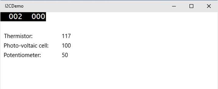
If success, you can see sensor values via I2C on app UI. The following is a sample output.
All materials on the site are licensed Creative Commons Attribution-Sharealike 3.0 Unported CC BY-SA 3.0 & GNU Free Documentation License (GFDL)
If you are the copyright holder of any material contained on our site and intend to remove it, please contact our site administrator for approval.
© 2016-2026 All site design rights belong to S.Y.A.