Getting Started with Windows Remote Arduino (2015)
4. Analog I/O
This chapter explains how to work with Arduino Analog I/O via WRA.
4.1 Getting Started
Arduino board provides Analog I/O which can be connected to sensor or actuator devices. In this chapter, we try to access Arduino Analog I/O using Windows Remote Arduino. There are two scenarios for our cases:
· Controlling RGB LED
· Reading Analog input using Potentiometer
All scenarios use USB for connectivity between Arduino and PC.
Let's start.
4.2 Demo Analog Output: RGB LED
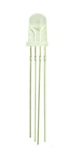
In this scenario we build a Windows Universal application to control RGB LED color using Arduino Analog output (PWM). RGB LED has 4 pins that you can see it on Figure below.
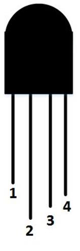
To understand these pins, you can see the following Figure.
Note:
· Pin 1: Red
· Pin 2: Common pin
· Pin 3: Green
· Pin 4: Blue
Now we can start to build a Windows Universal application and hardware implementation.
4.2.1 Arduino Analog output (PWM)
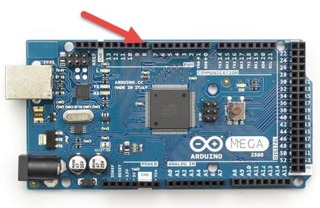
Please be careful if you want to work with Arduino PWM. If you have Arduino Mega, you will see PWM label so you obtain PWM pins easily but if you have Arduino Uno, it writes DIGITAL (PWM ~). It means your PWM pins can be found on DIGITAL pins which pin with ~, for instance, ~3,~5,~6,~9, ~10, ~11.
For Arduino Mega 2560, you can see PWM pins on picture below (see red arrow).
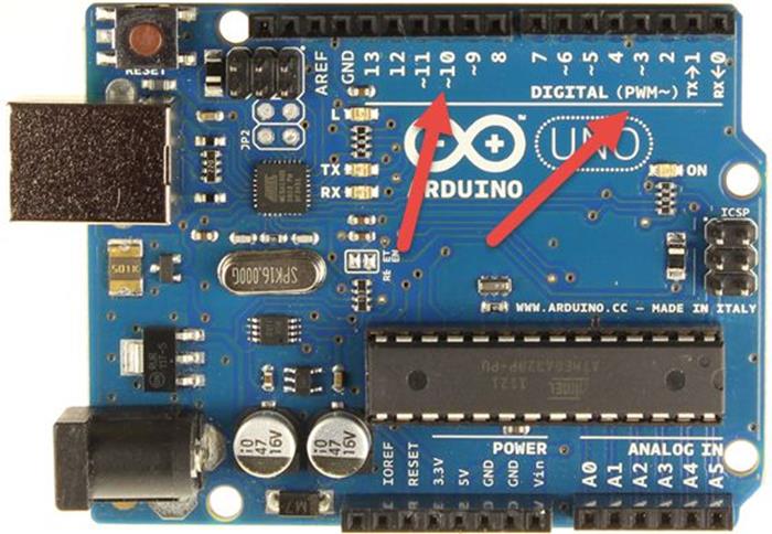
For Arduino Uno R3, you can see PWM pins as below.
4.2.2 Wiring
For our testing, we configure the following PWM pins.
Arduino Mega 2560:
· RGB LED pin 1 (red) is connected to Arduino PWM pin 4
· RGB LED pin 2 is connected to Arduino VCC 5V
· RGB LED pin 3 (green) is connected to Arduino PWM pin 3
· RGB LED pin 4 (blue) is connected to Arduino PWM pin 2
Arduino Uno R3:
· RGB LED pin 1 (red) is connected to Arduino PWM pin 9
· RGB LED pin 2 is connected to Arduino VCC 5V
· RGB LED pin 3 (green) is connected to Arduino PWM pin 10
· RGB LED pin 4 (blue) is connected to Arduino PWM pin 11
Here is a sample implementation with Arduino Uno R3.
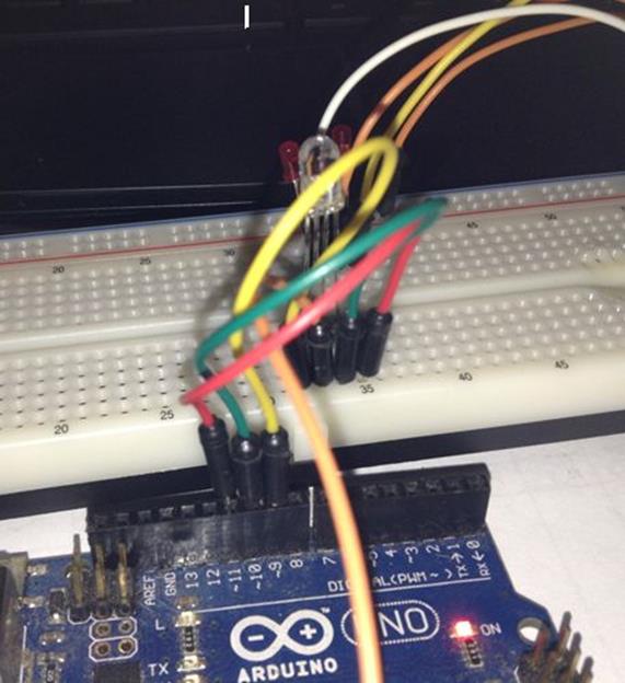
4.2.3 Writing Program
Firstly, create a new project, called RGBDemo. Follow instructions to create and configure the project as explained on section 2.3.2, 2.3.3 and 2.3.4.
Now we modify MainPage.xaml.cs file. Add these namespace.
using Microsoft.Maker.Serial;
using Microsoft.Maker.RemoteWiring;
Declare some variables.
private UsbSerial connection;
private RemoteDevice arduino;
private const byte RED = 9;
private const byte GREEN = 10;
private const byte BLUE = 11;
private DispatcherTimer timer;
private int index = 1;
We define InitMRA(), SetColor() and ColorDemo() methods.
private void InitWRA()
{
connection = new UsbSerial("VID_2341", "PID_0043");
arduino = new RemoteDevice(connection);
connection.ConnectionEstablished += Connection_ConnectionEstablished;
connection.begin(57600, SerialConfig.SERIAL_8N1);
}
private void SetColor(ushort red, ushort green, ushort blue)
{
arduino.analogWrite(RED, red);
arduino.analogWrite(GREEN, green);
arduino.analogWrite(BLUE, blue);
}
private void ColorDemo(int index)
{
if(index==1)
SetColor(255, 0, 0); // red
if (index == 2)
SetColor(0, 255, 0); // green
if (index == 3)
SetColor(0, 0, 255); // blue
if (index == 4)
SetColor(255, 255, 0); // yellow
if (index == 5)
SetColor(80, 0, 80); // purple
if (index == 6)
SetColor(0, 255, 255); // aqua
}
A timer is used to running our RGB LED which consists of 6 color demo by calling ColorDemo().
private void Connection_ConnectionEstablished()
{
System.Diagnostics.Debug.WriteLine("Connected");
arduino.pinMode(RED, PinMode.PWM);
arduino.pinMode(GREEN, PinMode.PWM);
arduino.pinMode(BLUE, PinMode.PWM);
index = 1;
timer = new DispatcherTimer();
timer.Interval = TimeSpan.FromMilliseconds(500);
timer.Tick += Timer_Tick;
timer.Start();
}
private void Timer_Tick(object sender, object e)
{
ColorDemo(index);
index++;
if (index > 6)
index = 1;
}
We call InitWRA() method on class constructor
public MainPage()
{
this.InitializeComponent();
this.Unloaded += MainPage_Unloaded;
InitWRA();
}
private void MainPage_Unloaded(object sender, RoutedEventArgs e)
{
arduino.Dispose();
}
4.2.4 Testing
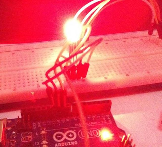
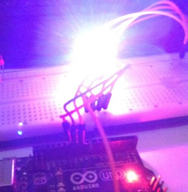
Compile and run the program. You should see several color on RGB LED.
The following is a sample demo on RGB LED.
4.3 Demo Analog Input: Working with Potentiometer
In this section, we learn how to read analog input on Arduino board. For illustration, I use Potentiometer as analog input source. Our scenario is to read analog value from Potentiometer. Then, display it on app UI.
Let's start!.
4.3.1 Wiring
To understand Potentiometer, you see its scheme in Figure below.
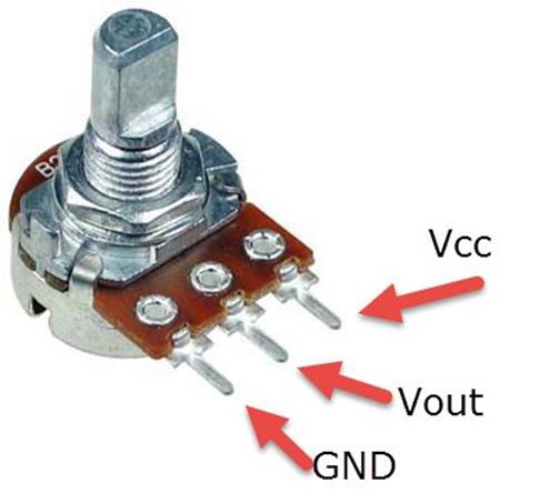
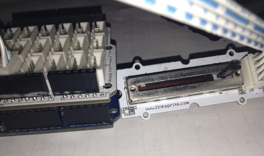
You can connect VCC to Arduino board VCC 5V. Vout to Arduino board Analog input A0. In addition, GND to Arduino board GND. The following is hardware implementation. I use slide potentiometer.
4.3.2 Writing Program
Firstly, create a new project, called RGBDemo. Follow instructions to create and configure the project as explained on section 2.3.2, 2.3.3 and 2.3.4.
The first step is to develop app UI on MainPage.xaml. We add two TextBlock. One of TextBlock will be used to display Analog value. The following is complete code for MainPage.xaml file.
<Page
x:Class="PotDemo.MainPage"
xmlns="http://schemas.microsoft.com/winfx/2006/xaml/presentation"
xmlns:x="http://schemas.microsoft.com/winfx/2006/xaml"
xmlns:local="using:PotDemo"
xmlns:d="http://schemas.microsoft.com/expression/blend/2008"
xmlns:mc="http://schemas.openxmlformats.org/markup-compatibility/2006"
mc:Ignorable="d">
<Grid Background="{ThemeResource ApplicationPageBackgroundThemeBrush}">
<TextBlock x:Name="textBlock" HorizontalAlignment="Left" Margin="10,28,0,0" TextWrapping="Wrap" Text="Pot Value:" VerticalAlignment="Top"/>
<TextBlock x:Name="txtVal" HorizontalAlignment="Left" Margin="80,28,0,0" TextWrapping="Wrap" Text="0" VerticalAlignment="Top"/>
</Grid>
</Page>
Now we modify MainPage.xaml.cs file. Add these namespace.
using Windows.ApplicationModel.Core;
using Microsoft.Maker.Serial;
using Microsoft.Maker.RemoteWiring;
We declare some variables for our app.
private UsbSerial connection;
private RemoteDevice arduino;
private const byte NUM_DIGITAL_PINS = 14; // Arduino Uno
private const byte POT = 0;
We define InitWRA() method and subscribe ConnectionEstablished event. On this event, we subscribe AnalogPinUpdateEvent event. On AnalogPinUpdateEvent event, we update TextBlock UI. Because we update UI from other thread, we use Dispatcher.RunAsync(). We define UpdateDate().
private void InitWRA()
{
connection = new UsbSerial("VID_2341", "PID_0043");
arduino = new RemoteDevice(connection);
connection.ConnectionEstablished += Connection_ConnectionEstablished;
connection.begin(57600, SerialConfig.SERIAL_8N1);
}
private void Connection_ConnectionEstablished()
{
System.Diagnostics.Debug.WriteLine("Connected");
arduino.pinMode(NUM_DIGITAL_PINS + POT, PinMode.ANALOG);
var val = arduino.analogRead(NUM_DIGITAL_PINS + POT);
txtVal.Text = Convert.ToString(val);
arduino.AnalogPinUpdatedEvent += Arduino_AnalogPinUpdatedEvent;
}
private async void UpdateData(ushort value)
{
await CoreApplication.MainView.CoreWindow.Dispatcher.RunAsync(Windows.UI.Core.CoreDispatcherPriority.Normal,
() =>
{
txtVal.Text = Convert.ToString(value);
});
}
private void Arduino_AnalogPinUpdatedEvent(byte pin, ushort value)
{
if (pin == POT)
{
UpdateData(value);
}
}
Finally, we call InitWRA() on class constructor.
public MainPage()
{
this.InitializeComponent();
this.Unloaded += MainPage_Unloaded;
InitWRA();
}
private void MainPage_Unloaded(object sender, RoutedEventArgs e)
{
arduino.Dispose();
}
Save this code.
4.3.3 Testing
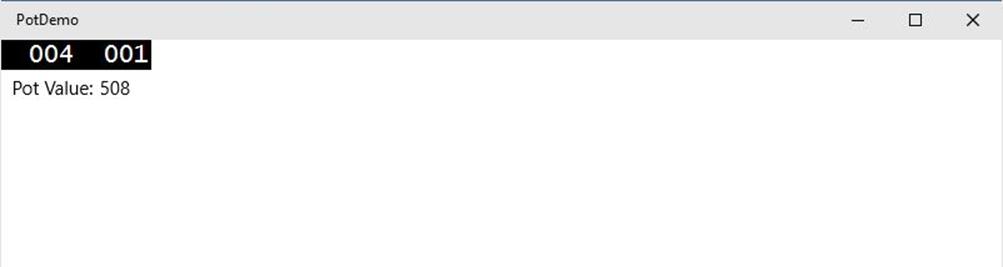
Compile and run this program. If success, you can see analog value on UI.
All materials on the site are licensed Creative Commons Attribution-Sharealike 3.0 Unported CC BY-SA 3.0 & GNU Free Documentation License (GFDL)
If you are the copyright holder of any material contained on our site and intend to remove it, please contact our site administrator for approval.
© 2016-2026 All site design rights belong to S.Y.A.