The Arduino Inventor's Guide (2017)
9 Drag Race Timer
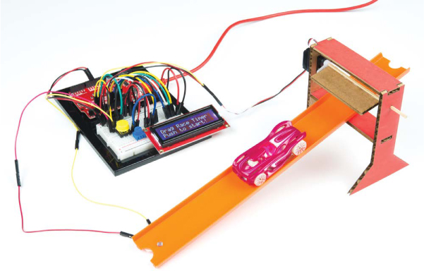
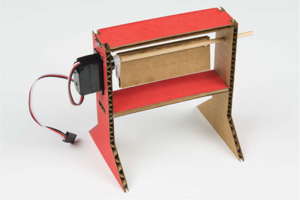
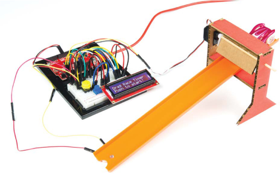
In Project 4, you built a reaction timer to measure how fast you can hit a button. In this project, you’ll build on the techniques you learned there to make a race timer for a Hot Wheels-inspired race track (see Figure 9-1). We’ll show you how to display the finish time on a small, portable LCD screen so that you can detach your project from your computer. We’ll also show you how to hack this project to add a second track and indicator lamps (LEDs) to show which car has won. Are you ready?
FIGURE 9-1: The completed Drag Race Timer
MATERIALS TO GATHER
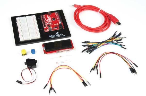
Many of the parts used in this project will be familiar to you already (see Figures 9-2 and 9-3). We’ll introduce only one new part: the 16 × 2 character LCD that you’ll use to display your race time directly, rather than displaying it in the Serial Monitor on your computer screen.
NOTE
In “Going Further” on page 273, we’ll show you how to modify your Drag Race Timer so you can race two cars and display the winning time. The standard SparkFun Inventor’s Kit includes one photoresistor (SEN-09088), but you’ll need two for this final hack. Thankfully, the photoresistor is a pretty inexpensive part, so you could either buy another one or partner with a friend who has an Inventor’s Kit to build the two-player version.
Electronic Parts
• One SparkFun RedBoard (DEV-13975), Arduino Uno (DEV-11021), or any other Arduino-compatible board
• One USB Mini-B cable (CAB-11301 or your board’s USB cable)
• One solderless breadboard (PRT-12002)
• One 10 kΩ resistor, or two if you want to build the two-player version (COM-08374, or COM-11508 for a pack of 20)
• One photoresistor (SEN-09088), or two* if you want to build the two-player version
• One push button (COM-10302)
• One 10 kΩ potentiometer (COM-09806)
• One 16 × 2 character LCD (LCD-00255)
• One submicro size servo motor (ROB-09065)
• Male-to-male jumper wires (PRT-11026)
• Male-to-female jumper wires (PRT-09140*)
NOTE
The parts marked with an asterisk (*) do not come with the standard SparkFun Inventor’s Kit but are available in the separate add-on kit.
FIGURE 9-2: Components for the Drag Race Timer
Other Materials and Tools
• Craft knife
• Metal ruler
• Needle-nose pliers
• Wire cutters
• Masking tape
• Glue (hot glue gun or craft glue)
• Cardboard (about 8.5 × 11 inches), a small cardboard box, or thick cardstock
• Bamboo skewer
• Enclosure template (see Figure 9-15 on page 266)
• Hot Wheels or other small toy cars to race (not shown)
• (Optional) Toy car race track (not shown)
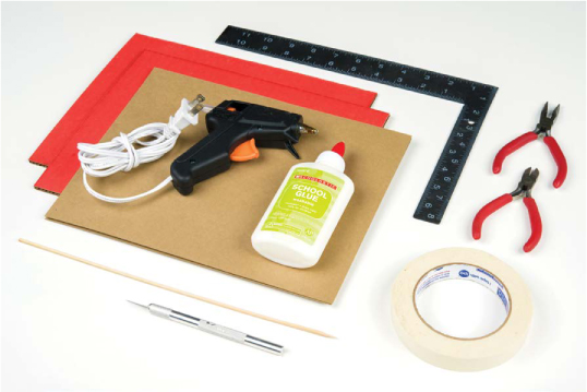
FIGURE 9-3: Recommended tools and materials
In previous projects, we’ve used the Serial Monitor to display information sent from the Arduino on your computer. In this project, we’ll show you how to add an LCD directly to your project, a skill well worth learning. The LCD requires a lot of wires, but don’t worry— we’ll take it one step at a time. After you’ve mastered the use of this part, you can go back and add it to some of your past projects to make them fully portable!
NEW COMPONENT: THE 16 × 2 CHARACTER LCD
LCD is short for liquid crystal display. Invented over 40 years ago, liquid crystal technology is used in digital watches, alarm clocks, projectors, televisions, computer monitors, and more.
The LCD you’ll use in this project is a simple monochromatic display, meaning it displays only one color. Beneath the screen of the display is a layer of liquid crystal. This is a unique chemical that, when a small electric current is applied to it, changes from transparent to opaque. Combined with a backlight or a reflective mirror, liquid crystal is used to build very simple displays. Light comes through or is blocked depending on which areas of the liquid crystal electricity is applied to—which means you can make shapes if you can control the current.
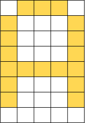
The 16 × 2 character LCD displays up to 32 characters of information, each of which is broken down into a 5 × 8 pixel matrix. Each individual pixel can be made either opaque or transparent depending on the applied electric current, controlled by the Arduino. The letter A, for example, will display on the LCD screen when the yellow pixels in Figure 9-4 are made opaque.
FIGURE 9-4: The uppercase letter A represented on a 5 × 8 pixel matrix
There are 40 individual pixels in a single character, each controlled by the Arduino, meaning there are 1,280 different control lines! Thankfully, the LCD used in this project has a special parallel interface LCD driver IC by Hitachi called the HD44780. This chip allows you to display almost any character on the screen using just six control lines from the Arduino. Figure 9-5 shows the pins on an LCD.
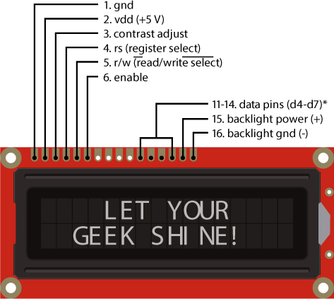
FIGURE 9-5: A simple 16 × 2 character LCD
NOTE
The LCD can use up to eight pins for data (d0–d7), but the way we are going to use the LCD, it only uses four. These are labeled d4–d7.
The LCD has a total of 16 pins, but this project uses only pins 1–6 and 11–16. The pins are numbered 1 through 16 from left to right (with the pins at the top of the screen). Table 9-1 describes each of the pins on the LCD. In some datasheets you might see a line over a label, as with the ![]() label on pin 5. This line indicates that the feature is an active low, which means the pin is activated at low voltage. So, in this case, when you want to write to the LCD, pin 5 needs to be set to LOW. We’ll discuss this more in “Connect the Data and Control Wiring” on page 255.
label on pin 5. This line indicates that the feature is an active low, which means the pin is activated at low voltage. So, in this case, when you want to write to the LCD, pin 5 needs to be set to LOW. We’ll discuss this more in “Connect the Data and Control Wiring” on page 255.
TABLE 9-1: Pin descriptions for 16 × 2 character LCD
|
PIN |
DESCRIPTION |
|
1 |
Ground (GND) |
|
2 |
VDD power for the LCD (5 V) |
|
3 |
Contrast adjust (0–5 V) |
|
4 |
Register select (RS) |
|
5 |
|
|
6 |
Enable |
|
7–10 |
Data lines d0–d3 (not used) |
|
11–14 |
Data lines d4–d7 (data transferred in 4 bits at a time) |
|
15 |
Backlight power (5 V) |
|
16 |
Backlight ground (GND) |
Rather than having to control each of the 40 pixels for each character separately, the HD44780 driver chip interprets data sent over by the Arduino using four data lines and two control lines and converts this into the character to display. To further simplify the interface, the Arduino community has written an LCD library for writing code to the LCD. We’ll look at that in the code.
DRAG RACE TIMER OPERATION
Before we start wiring the electronics, let’s discuss how the sketch will function. We designed this race timer so that when we push a button the servo moves up, opening the starting gate that allows the car to roll down the track. At the same time, the Arduino records the starting time and waits to see when the car reaches the photoresistor at the bottom of the track, which uses the same light-sensor circuit used in the Night-Light in Project 5. You’ll embed the light sensor in the center of the track so that when the car passes over it, it will create a shadow that the Arduino can detect. When the Arduino detects the shadow, it will record the stopping time and calculate the total time as the stopping time minus the starting time. If this seems similar to the Reaction Timer from Project 4, that’s because it is!
BUILD THE LCD CIRCUIT
You’ll start by building the LCD circuit. The LCD has 16 pins in total, but you’ll use just 12 of them. Figure 9-6 shows the schematic for the LCD wiring.
FIGURE 9-6: Schematic diagram of LCD wiring
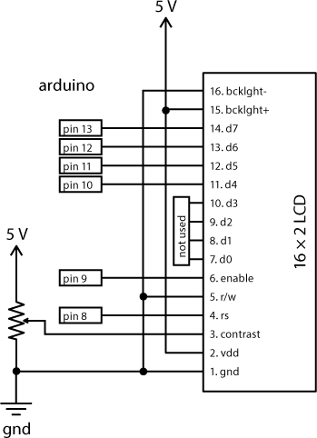
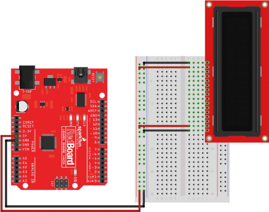
With 16 pins, the LCD will take up 16 rows on the breadboard, so you’ll have to be careful about positioning with this project. You’ll mount the LCD in the first 16 rows on the right side of the breadboard. Be sure to connect the power and ground from the Arduino to the power and ground rails on the left side of the breadboard.
Note that the pins on the LCD are not labeled. As we walk you through wiring it up, we’ll refer to the pins on the LCD in order, starting with pin 1 at the bottom.
Power the LCD
The LCD has two separate power supplies for the backlight and for the control logic. You’ll need to wire these separately.
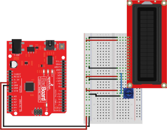
Connect pin 1 of the LCD to GND and pin 2 of the LCD to 5 V using the power rails on the breadboard. This provides power for the LCD’s control circuitry and the HD44780 LCD driver chip. Next, connect pin 15 on the LCD to 5 V and pin 16 on the LCD to GND, again using the power rails. These two connections power the LCD’s built-in backlight (see Figure 9-7).
FIGURE 9-7: Connect the power for the LCD and the backlight.
Control the Contrast
You can adjust the contrast on the LCD screen. To do so, you control the voltage on pin 3 of the LCD using a simple voltage divider circuit with a potentiometer, similar to what you did for the Balance Beam in Project 6. Recall that a potentiometer is the same thing as a variable resistor: it has three pins, and as you turn the knob the resistance between the center pin and either of the end pins changes. If you connect the top and bottom pins of the potentiometer to 5 V and GND, you have a variable voltage divider where the voltage on the center pin will vary between 5 V and GND depending on how far you turn the knob (see Figure 9-8).
FIGURE 9-8: Potentiometer schematic connected up as a variable voltage divider
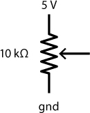
Add the potentiometer to the breadboard just below the LCD. Connect the outside pins of the potentiometer to 5 V and GND, and connect the center pin to pin 3 on the LCD for the contrast control.
Now all you need to do is add the data and control wiring for the LCD.
Connect the Data and Control Wiring
You need seven more wires to connect to the LCD, including four data lines and three control lines. Pin 5 on the LCD is the read/write functionality that allows the Arduino to read from and write data to the display. You’re only going to use this read/write connection to send data to the LCD, or write to the device, so you can connect this to ground, known as “tying the pin low.” If you look back at Table 9-1, you’ll notice that the ![]() label has a line over Write. As we mentioned earlier, this notation is often used in datasheets and documentation to indicate that a low signal will activate this feature. A low input is equivalent to ground, so add a wire to connect pin 5 of the LCD to GND, as shown in Figure 9-9.
label has a line over Write. As we mentioned earlier, this notation is often used in datasheets and documentation to indicate that a low signal will activate this feature. A low input is equivalent to ground, so add a wire to connect pin 5 of the LCD to GND, as shown in Figure 9-9.
FIGURE 9-9: Connect pin 5 of the LCD to GND for the ![]() control.
control.
The final six wires will connect the LCD to the Arduino. Pins 11–14 on the LCD are the four data lines the Arduino will use to send information to the LCD. Connect these to the Arduino pins 10, 11, 12, and 13, as shown in Figure 9-10. The wires should go straight across from the Arduino board to the LCD without crossing.
The last two connections are Enable at pin 6 and Register Select at pin 4. The Enable pin is used to signal the data transfer to the LCD, and the Register Select pin determines whether the data represents a character to display or an instruction, like clearing the screen or moving the cursor; this gives you greater control over what’s displayed on the screen. Connect pin 9 on the Arduino to pin 6 on the LCD, and pin 8 on the Arduino to pin 4 on the LCD, as shown in Figure 9-10.
FIGURE 9-10: Final wiring of the LCD circuit
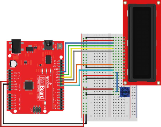
Table 9-2 shows the LCD screen connections to help you make sure you have everything connected correctly.
TABLE 9-2: LCD pin connections
|
LCD PIN |
CONNECTION |
|
16 |
GND |
|
15 |
5 V |
|
14 |
Arduino pin 13 |
|
13 |
Arduino pin 12 |
|
12 |
Arduino pin 11 |
|
11 |
Arduino pin 10 |
|
10 |
N/A |
|
9 |
N/A |
|
8 |
N/A |
|
7 |
N/A |
|
6 |
Arduino pin 9 |
|
5 |
GND |
|
4 |
Arduino pin 8 |
|
3 |
Middle pin of potentiometer |
|
2 |
5 V |
|
1 |
GND |
Test the LCD
Before you wire up more of the circuit, test it to make sure it’s working as expected so far. Connect your Arduino to your computer.
As soon as you apply power, the backlight should turn on. Try turning the potentiometer knob. Even with nothing displayed on the LCD, you should see the contrast of the screen change as you twist, from all dark at its lowest to 32 brightly lit rectangles at its highest.
If you don’t see this, double-check the wiring. Make sure that all of the power connections to the LCD match Table 9-2.
Once you have the LCD working, copy the code from Listing 9-1 into Arduino and upload it to your device. This simple example should display the text SparkFun Arduino on the first line and a running counter on the second line.
LISTING 9-1: Test code to display text and a running millis() counter to the LCD
➊ #include<LiquidCrystal.h>
➋ LiquidCrystal lcd(8, 9, 10, 11, 12, 13);
void setup()
{
➌ lcd.begin(16, 2); //initializes interface to LCD
➍ lcd.clear();
➎ lcd.print("SparkFun Arduino");
}
void loop()
{
➏ lcd.setCursor(0, 1); //move cursor to the 2nd line
//(col 0, row 1)
➐ lcd.print(millis()/1000); //print the number of
//seconds elapsed
}
Let’s take a look at what’s going on in this example. First, it includes the LiquidCrystal.h library ➊ created by the Arduino community to simplify the six different control and data lines. This will make it easier for you to send instructions to the LCD.
Next, this code creates an object named lcd that uses the LiquidCrystal library ➋. Notice that this time when you create the object, you pass it a set of parameters that correspond with the LCD pins: the Register Select, Enable, and four data pins. This is where you configure which pin controls each function on the LCD. In some documentation, you may see this command as LiquidCrystal lcd(RS, Enable, d4, d5, d6, d7).
You may be wondering why we don’t use four of the LCD pins. This LCD is able to transfer data on either four or eight data lines. According to the datasheet on the LCD, when you use four data lines, you use the top four pins on the LCD—the pins labeled d4, d5, d6, and d7. While it takes the Arduino twice as long to transfer data to the LCD this way, this helps to keep the circuit as simple as possible, and remember, the Arduino operates with a 16 MHz clock. That’s really fast!
The LiquidCrystal library has around 20 different commands that simplify control of this LCD. In this example, we’ll show you a few basic commands that allow you to configure the screen size, clear the screen, display information, and move the cursor.
The setup() part of the sketch has a few instructions that will run just once when the Arduino starts up. The first of these is lcd.begin(16, 2); ➌, which sets up the size of the LCD as a 16 × 2 character LCD, allowing the library to correctly wrap text and move from one line to the next.
The next instruction, lcd.clear(); ➍, allows you to clear the screen before providing new text to display. It also resets the position of the cursor to the first character on the first line of the screen. Without this, the LCD would retain the last thing displayed.
Then, the command lcd.print("SparkFun Arduino"); ➎ displays the text SparkFun Arduino on the LCD. Because the lcd.clear() instruction just cleared the screen, this text will appear on the first line of the display. This string of text is exactly 16 characters long and should fill the entire first line of the LCD. This command is similar to Serial.print(), but with lcd.print() you don’t need to be connected to a computer or have the Serial Monitor open to see text and information from your device.
The loop() refreshes the screen with new information each time it repeats. First it moves the cursor to the second line of the LCD using lcd.setCursor(0, 1); ➏ so it doesn’t overwrite the SparkFun Arduino text on the first line. The two numbers used in the setCursor() method indicate the position of the character (0) and the row (1). As is common in a lot of programming environments, Arduino counts starting with an index of 0, not 1.
NOTE
The LiquidCrystal library only works with character LCD displays. Graphic LCD screens are also available, but they use a different library called OpenGLCD, which allows you to display graphics such as lines, rectangles, and circles as well as text.
Finally, the sketch prints a counter ➐ using another lcd.print() instruction. This counter uses the millis() function, which reports the number of milliseconds since the Arduino was powered on. Dividing this value by 1,000 shows a counter in seconds. We will use a similar technique for the race timer.
Now, can you figure out how to change the text to display your name on the first line? How about changing the time display to show the time elapsed in minutes instead of seconds? Play around with the code example until you’re comfortable with displaying data to the LCD. With just six GPIO pins from your Arduino, you can add an LCD readout to any project!
This example demonstrates the most commonly used instructions in the Arduino LiquidCrystal library, but if you want to check out the other commands that you can use, see https://www.arduino.cc/en/Reference/LiquidCrystal/.
Now that you have the LCD circuit working, it’s time to add the button, servo, and light-sensor circuit.
ADD THE REST OF THE ELECTRONICS
The Drag Race Timer will use a few parts that you’ve already put together in previous projects: a push button to start the race, a servo to control the starting gate for the car, and a photo resistor to detect when the car reaches the end of the track. Figure 9-11 shows schematic diagrams of these three additional components.
FIGURE 9-11: Schematic diagrams for additional components in the Drag Race Timer
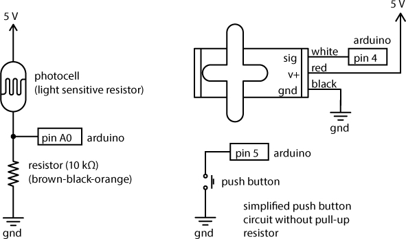
Place a push button on the breadboard so that two legs are on either side of the center divide, and connect two of the legs on one side to pin 5 on the Arduino and GND. The parts will fill up most of the breadboard, so pay close attention to the rows on the breadboard and how the components are connected. To save space, this project uses the push button without the external pull-up resistor used in Project 4 with the Reaction Timer. Instead, we’ll enable a pull-up resistor in the code.
Next, connect the servo motor that will open the starting gate. Using three male-to-male jumper wires, connect the signal wire (either yellow or white) to pin 4 on the Arduino, the red wire to the 5 V rail, and the black wire to the GND rail.
Finally, add the light-sensor circuit with a voltage divider circuit. Connect one end of a photoresistor to the 5 V power rail and the other end to the GND power rail, via a 10 kΩ pull-down resistor placed directly in the power rail. Connect the row that has both the photoresistor and the 10 kΩ pull-up resistor to pin A0 on the Arduino. This circuit should look similar to the circuit you used in the Night-Light in Project 5.
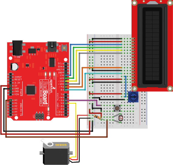
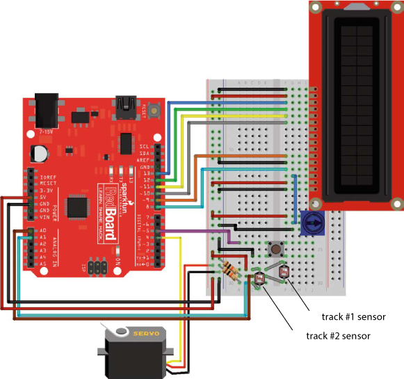
There are a lot of components in this circuit, so take your time and double-check your wiring against the diagram in Figure 9-12.
FIGURE 9-12: Complete electronics for the Drag Race Timer, including a starting button and gate
PROGRAM THE DRAG RACE TIMER
Now let’s put it all together. Start a new sketch, and enter the code from Listing 9-2 or download it from https://www.nostarch.com/arduinoinventor/. This example will bring together several concepts and ideas we’ve used separately in past projects.
LISTING 9-2: Drag Race Timer sketch
➊ #include<LiquidCrystal.h>
#include<Servo.h>
LiquidCrystal lcd(8, 9, 10, 11, 12, 13);
➋ Servo startingGate;
➌ const byte buttonPin = 5;
const byte servoPin = 4;
const byte finishSensor1Pin = A0;
const int darkThreshold = 500;
➍ int finishSensor1;
boolean finishFlag = false;
long startTime;
long stopTime;
float raceTime;
void setup()
{
➎ pinMode(buttonPin, INPUT_PULLUP);
startingGate.attach(servoPin, 1000, 2000);
startingGate.write(0);
➏ lcd.begin(16, 2);
lcd.clear();
lcd.print("Drag Race Timer");
lcd.setCursor(0, 1);
lcd.print("Push to start!");
➐ while (digitalRead(buttonPin) == HIGH)
{
}
lcd.clear();
lcd.print("Go!");
startingGate.write(180);
startTime = millis();
}
void loop()
{
➑ finishSensor1 = analogRead(finishSensor1Pin);
➒ if ((finishFlag == false) && (finishSensor1 < darkThreshold))
{
finishFlag = true;
stopTime = millis();
raceTime = stopTime - startTime;
lcd.clear();
lcd.print("Finish Time:");
lcd.setCursor(0, 1);
➐ lcd.print(raceTime / 1000, 3);
}
}
Let’s take a look at how all this works. First, the sketch includes two libraries using the #include directive ➊, LiquidCrystal.h and Servo.h. Next, it initializes a LiquidCrystal object named lcd, similar to Listing 9-1, and a Servoobject named startingGate ➋.
Then, the sketch declares a set of constants for the pin connections used for the button, servo, and photoresistor circuits ➌. This means that, as you make changes and modifications, if you need to move a wire to a different pin on the Arduino, you’ll only have to change a single number in the code. The last constant, a threshold value named darkThreshold, is used to set the light level to detect when the car is blocking the light sensor. Here it’s set to 500, roughly in the middle of the range of 0–1023, but you may need to adjust this value to suit the environment of your own room.
Next, the sketch declares a few variables ➍. The finishSensor1 variable is used to store the raw value of the photoresistor sensor. The next variable, finishFlag, is a state variable, which is used to keep track of what state the sketch is in. The finishFlag variable is initialized to false and is used to indicate when the race is over (like the flag waved at the finish line to mark the winner of a Formula One race). We’ll set it later in the code based on the input value from the sensor. The next three variables are used to calculate the race time using the built-in millis() timer in Arduino.
Now, the setup() part of the code sets up the button pin to use an internal pull-up resistor that’s built into the Arduino by declaring the pin mode as an INPUT_PULLUP ➎. This trick removes the need for the external pull-up resistor used in Project 4.
Next, the sketch initializes the servo motor and sets its default position to 0. This will be the position of the starting gate when it’s down.
The sketch then displays a little information to the LCD ➏ to let the user know how to start the race. These few lines of code set up the LCD, clear the screen, and display two lines of text. Be careful that your text is limited to 16 characters per line; any more than 16, and your characters will run off the screen to the right. The code then waits for a button press using the blocking while() loop technique ➐ used in the Reaction Timer; this blocks the sketch from proceeding until the button is pressed. When the button is pressed, digitalRead(buttonPin) will read LOW and the code will move the servo to the up position and set the startTime variable.
In the loop(), the sketch reads the light sensor and stores its current reading to the variable finishSensor1 ➑. The sensor will be embedded at the end of the ramp. The car will roll over it as it crosses the finish line, covering the sensor and blocking most of the light. Similar to the Night-Light sketch in Project 5, the sketch will compare the value of the sensor to the darkThreshold value.
NOTE
Your sensor needs to be in a decently lit area so that the contrast between the sensor being lit and being shaded is great enough to cause that drop in voltage. Be aware that overhead lights can create a false detection if your body casts a shadow over the sensor. If you want to make sure that the sensor works well, get a small desk lamp and set it over the sensor.
Remember that in the time it takes the car to pass the sensor, the loop() may repeat several times. Because we only want to look for the first moment the car crosses the finish line, the sketch uses a compound if() statement ➒ to capture the moment when the finishFlag variable is false and the finish sensor is blocked (that is, its value is less than darkThreshold). The && indicates a logical AND (see “Compound Logic Operators” on page 264). Pay careful attention to the number of parentheses used in the if() statement—they indicate order of operation and how the logic is used.
Now, inside the if() statement, the finishFlag state variable switches to true. Because the finishFlag state variable is now set to true, the compound if() statement will only catch the first moment the car crosses the sensor.
The sketch then records the stopping time and calculates the elapsed race time. Finally, the sketch prints the race time to the LCD.
The raceTime variable is declared as a float (floating-point variable) so it can store numbers with decimals. By default, the lcd.print() method will display two decimal places of precision for a floating-point value, but you can add a second parameter to the lcd.print() method to specify more or less. At ➓, the sketch calculates the number of seconds elapsed by dividing the millisecond count by 1,000. The extra 3 in the instruction lcd.print(raceTime / 1000, 3);tells Arduino to display three values past the decimal point, so the time will be accurate to the millisecond. Don’t forget the last two curly brackets in the code. Double-check to make sure that your code matches Listing 9-2, and upload the sketch to your device.
COMPOUND LOGIC OPERATORS
In Chapter 4, we introduced simple logical comparison operators to compare two values. Recall that logic comparisons or expressions can only be either true or false. In programming, there are times when you need to compare multiple conditions together; for example, when you need to run some code only when a variable is false AND a sensor value is less than the threshold: ((finishFlag == false) && (finishSensor1 < darkThreshold)). Here, notice that the logic comparisons are grouped together in parentheses on either side of the compound AND (&&).
A combination of two or more logic comparisons is known as a compound logic expression. Expressions are evaluated (or read) from left to right. To keep everything together and observe the correct order of operations, it’s a good idea to use parentheses to separate out the individual expressions. The two main operators used to combine logic expressions are AND and OR, which are described in the following table.
|
SYMBOL |
COMPOUND OPERATOR |
DESCRIPTION |
|
(expression A) && (expression B) |
AND |
Both expression A and expression B must be true. |
|
(expression A) || (expression B) |
OR |
Either expression A or expression B must be true. |
A QUICK TEST
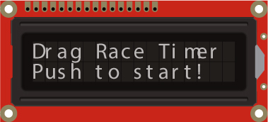
If you have everything wired up correctly and the code uploaded successfully, you’ll hear the servo motor move to the 0 degree position and see a message displayed on the LCD, as shown in Figure 9-13. If the text is garbled or otherwise incorrect, double-check the wiring of the LCD, push button, and light sensor.
FIGURE 9-13: LCD display text at the start of the race
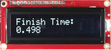
Push the button and see what happens. The servo motor should move, and the display should change to the message “Go!” Now, cover the photoresistor with your finger. The LCD should display the time elapsed since you pressed the button and covered the photo-resistor (Figure 9-14).
With the electronics all working properly, it’s time to build the starting gate and track. If the sensor is not behaving as expected, try changing the darkThreshold value. If it’s too sensitive or triggering immediately, reduce the value of darkThreshold. If it’s not reacting when you cover up the sensor, try increasing the value. After you’ve made these changes, reupload your code and test it again.
FIGURE 9-14: LCD display with time elapsed
BUILD THE DRAG RACE TRACK
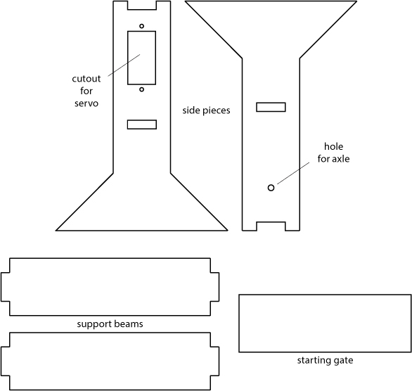
The Drag Race Track includes a starting tower with a rotating gate that controls the release of the car onto the track. For the track, you can either use a section of a toy car race track or build your own from cardstock. The template for the tower is shown in Figure 9-15. You can download a PDF of this template from https://www.nostarch.com/arduinoinventor/.
FIGURE 9-15: Template of cardboard cutout pieces for starting gate (not full size)
Build the Starting Tower
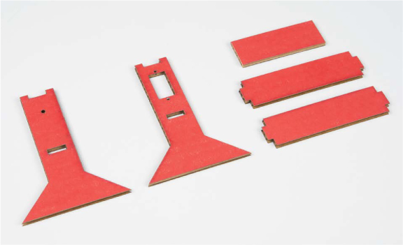
Carefully cut the template out from a sheet of cardboard (see Figure 9-16). The template has an opening for mounting the servo on one side and a hole on the other to mount the bamboo skewer axle for the starting gate. The other pieces are the support beams and the starting gate.
FIGURE 9-16: Trace the template and carefully cut out the pieces using a sharp craft knife.
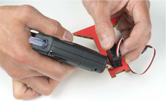
With the pieces cut out, first mount the servo in the opening, labeled in Figure 9-15. Insert the servo from the outside of the support beam so that the servo horn faces in toward the car. You can use the small screws included with the servo, or a small amount of glue, to secure the servo in place as shown in Figure 9-17. Don’t attach the servo horn just yet. You’ll attach that to the starting gate in the next step.
FIGURE 9-17: Securing the servo using hot glue
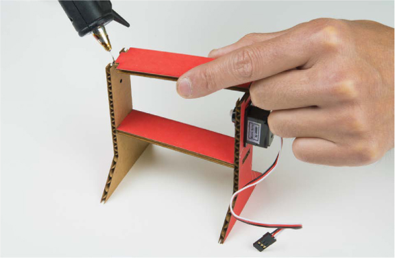
Now, glue the two support beams in place. The lower support beam will insert into the slots cut into each of the side pieces. The top support beam should fit right into the notch on the top of each side piece. Use a small dab of glue to secure each of these pieces in place. When you’re done, you should have a starting support tower like the one in Figure 9-18.
FIGURE 9-18: Adding the support beams
Assemble the Starting Gate
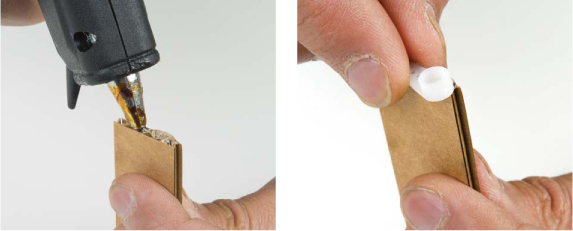
To build the starting gate, you’ll need a piece of cardboard that is 2.5 × 1 inches and a short length of bamboo skewer or thin coffee stirring rod. This will serve as an axle for the starting gate. To start, add a small bead of glue to the edge of the starting gate piece, and glue the servo horn on so that the hub hangs just off the edge, as shown in Figure 9-19.
FIGURE 9-19: Gluing the servo horn onto the edge of the starting gate
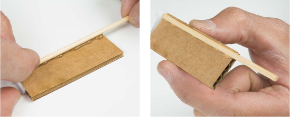
Cut down the bamboo skewer to 3.5 inches. Place a line of glue along the edge, and line the axle up with the hub of the servo horn, as shown in Figure 9-20.
FIGURE 9-20: Gluing the axle to the starting gate
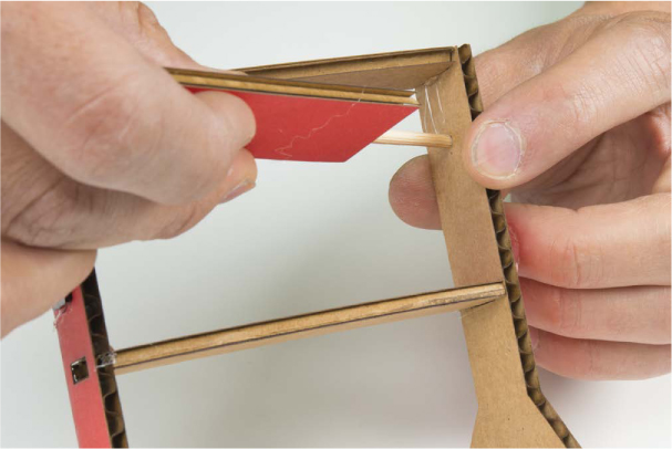
Plug in your Arduino and push the reset button to reset the position of the servo. Remember that the code will start off with the servo in the 0 degree position; this will be the down position, where the starting gate is holding the car in place. To place the starting gate into the support tower, first insert the axle into the hole on the side piece opposite of the servo, as shown in Figure 9-21. Keep in mind that when the gate opens, it will rotate clockwise.
FIGURE 9-21: Inserting the axle into the side piece for the starting gate
The finished starting tower with the gate is shown in Figure 9-22.
FIGURE 9-22: Completed starting tower
Now you need a track. You can use a standard Hot Wheels track, which will fit on the lower support, or build your own track. If you want to use a Hot Wheels track, skip ahead to “Add the Photoresistor” on page 270.
Build Your Own Track
To build your own track, you’ll need at least one sheet of cardstock, cut down to 3.5 × 11 inches. You can make several lengths of track and tape them together for a longer track, but for our example, we’ll just use a single track.
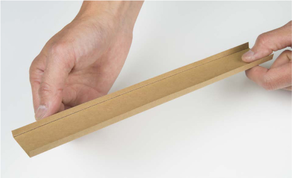
You’ll fold two side rails on the track. On each side, measure and mark a line that is a quarter inch from the edge. Now, fold along the lines so that you have a quarter-inch lip on each side of your track. (It’s often helpful to use a metal ruler or the edge of a table to make a nice straight fold in cardstock.) The lip will keep your car from flying off the track and also adds a small amount of structural integrity. Your track should look similar to the one pictured in Figure 9-23.
Now, using a small handheld hole punch, make a hole about a half inch from the end of your track for your photoresistor. If you don’t have a hole punch, a craft knife or sharp pencil will also work. Just be careful when cutting through the paper, and always use a cutting mat when using a knife. The hole needs to be just large enough for the head of the photoresistor to fit inside.
FIGURE 9-23: Completed track with two sides folded up
Add the Photoresistor
Whether you’re using a homemade track or a standard toy track, the next step is to add the photoresistor at the bottom of the ramp. The photoresistor will be your finish-line sensor. (There is a small hole at the end of a standard Hot Wheels track, slightly smaller than the diameter of the photoresistor sensor. Thankfully, the plastic track is flexible enough that you can simply press the head of the photo-resistor through this hole.)
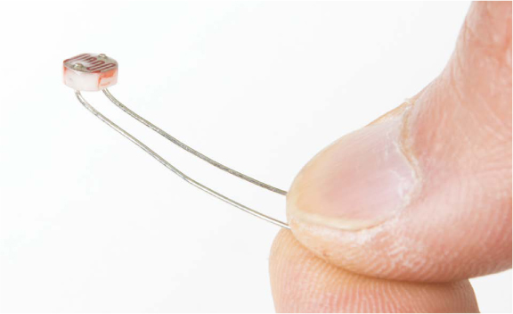
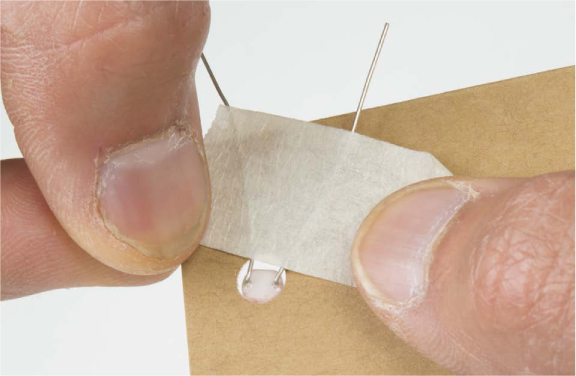
Remove the photoresistor from the breadboard and bend the legs at a right angle along the head so that it looks like Figure 9-24.
FIGURE 9-24: Bend the head of the photoresistor at a right angle.
Insert the head of the photoresistor through the hole in your track. Make sure that the photoresistor does not stick out too much, or your car will catch on it; the car should be able to roll over the sensor without interference. With the legs bent at right angles, you should be able to tape them down securely to the bottom side of the track, as shown in Figure 9-25.
FIGURE 9-25: Securing the photo resistor to the race track
Reconnect the photoresistor to your breadboard using a pair of male-to-female jumper wires. If you extended the track too far and can’t reach the breadboard, add more male-to-female jumpers to extend your wires as needed.
FEEL THE NEED FOR SPEED? CALCULATING AVERAGE SPEED
With this project you can accurately measure how long it takes the car to roll down the ramp and cross the finish line, but you don’t know how fast the car is moving—or do you?
Well, you have the total time it takes for the car to reach the bottom of the track, and you know the length of the track. With these two pieces of information, you can estimate how fast the car is moving. We describe this as an estimate because it’s really an average speed, as opposed to the exact speed of your car when it meets the sensor at the bottom of the ramp. If you watch as the car rolls down, you’ll see that it starts at the top of the ramp unmoving, then moves slowly, and then continues to speed up as it goes down the track.
Average speed is defined as distance traveled per unit of time. So, to find the average speed, you need to measure the length of the track and divide this value by the time elapsed.

Our track measures about 8.5 inches from the starting gate to the finish-line sensor, and in our last test we had a time of 0.581 seconds. If we divide these two numbers, we get an average speed of 14.6 inches per second.
![]()
Remember that this is the average speed of the car. For our simple setup with a straight ramp, this is roughly how fast the car is moving at the middle of the ramp, and since it wasn’t moving at the top of the ramp, this means it was moving at twice this speed at the bottom of the ramp. How fast is your car moving?
Test and Troubleshoot
Finally, rest the end of your race track without the photoresistor on the starting tower so that the ramp extends past the tower by about the length of your toy car (see Figure 9-26). This will be the starting position.
FIGURE 9-26: Finished Drag Race Timer with car ready to launch
If you haven’t already done so, plug the Arduino back into your computer or into a power source. Push the reset button to make sure that the sketch starts over, and find your favorite Matchbox or Hot Wheels car and set it behind the starting gate. Push the starting button and watch your car go!
How long did it take to reach the bottom? On our track, our toy cars took just over 0.5 seconds. Try a few different cars, or invite some friends over to see whose car is the fastest. If you tape a few pennies to your car, does it go faster? Experiment and see how different things affect the drag race time of your car.
GOING FURTHER
In this project, we introduced you to using the LCD to display information directly from your Arduino sketch. Here are a few ideas of how you can take what you’ve done in this project further.
Hack
Racing against yourself is only so much fun. Let’s look at how to add a second track and have two cars race against each other. (See Figure 9-27.) For this hack, you’ll need an extra photoresistor, which isn’t included in the standard SparkFun Inventor’s Kit. Find a friend who also has a kit, buy one separately, or find one in the additional parts kit for this book.
First you need to create a separate finish-line sensor circuit. We were able to sneak in one more photoresistor and a pull-down resistor circuit near the bottom of the breadboard, as shown in Figure 9-28. Connect the second photoresistor circuit to pin 2 on the Arduino through a 10 kΩ pull-down resistor, and connect the other leg to the 5 V power rail.
Place the photoresistor in the second track, and add male-to-female jumper wires to connect this to your circuit on the breadboard. Set your second track next to the first one on the starting tower. Now, it’s time to upload some new code that will use both sensors. You only need to add a few extra lines to allow for the two cars to race. Download the P9_TwoCarDragRaceTimer.ino file from https://www.nostarch.com/arduinoinventor/ and open it.
Let’s take a look at the additions to this code. First, the code adds a new constant and variable for the second photoresistor finishline sensor, finishSensor2Pin and finishSensor2.
Then, it checks which sensor was crossed first using a compound if() statement. If car #1 crosses first, finishSensor1 will be 0 and finishSensor2 will still be 1. Inside this if() statement, instructions display the winning information to the LCD and set the state variable, finishFlag, to true.
The else-if() statement checks whether car #2 crosses the finish line first; in this case, finishSensor2 will be 0 and finishSensor1 will still be 1. In the unlikely event that both cars do actually cross the line at the same time, this code does nothing. See if you can figure out how to add a draw feature in the event of a tie.
The code is full of comments to help explain more. Now, upload the code to your board and race! Whose car is fastest?
FIGURE 9-27: Drag Race Timer with two race tracks
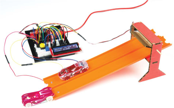
FIGURE 9-28: Adding a second photo-resistor for racing two cars at the same time
Modify
Now that you’ve seen how to use the LCD circuit, try going back and adding an LCD to one of the projects you’ve already built. In any of the projects where you used the Serial Monitor to display information, like the Reaction Timer from Project 4 or the Tiny Desktop Greenhouse in Project 7, you can replace the Serial Monitor with the LCD.
You’ll need to check the wiring and the pin configuration used; you’ll need six GPIO pins from your Arduino to control the LCD. If you want to see an example of the Reaction Timer project that uses the LCD, take a look at the tutorial we created on our InventorSpace at https://invent.sparkfun.com/cwists/preview/1145-sik-lcd-reaction-timer/.
All materials on the site are licensed Creative Commons Attribution-Sharealike 3.0 Unported CC BY-SA 3.0 & GNU Free Documentation License (GFDL)
If you are the copyright holder of any material contained on our site and intend to remove it, please contact our site administrator for approval.
© 2016-2026 All site design rights belong to S.Y.A.