The Arduino Inventor's Guide (2017)
3 The Nine-Pixel Animation Machine
We use monitors every day, on our phones, computers, tablets, and TVs. The displays on most present-day monitors are composed of millions of pixels, short for picture elements. Pixels are tiny points that the computer can light up in different colors; all the pixels together make up the text, images, and videos on the screen.
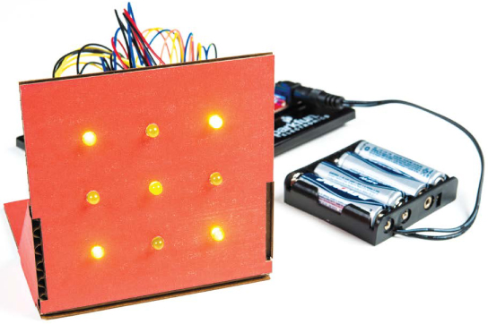
In this project, you’re going to build a simple monitor using LEDs. You’ll expand on your work with blinking LEDs and learn to use custom functions in Arduino. Finally, you’ll learn how to display secret characters on your very own Nine-Pixel Animation Machine. You can see ours in Figure 3-1.
FIGURE 3-1: A completed Nine-Pixel Animation Machine
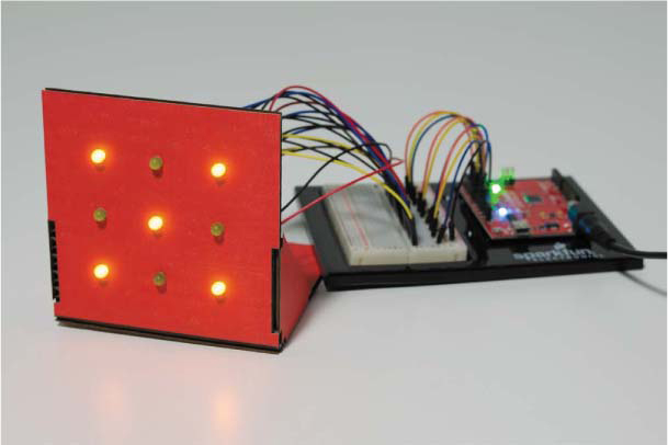
You can use the Nine-Pixel Animation Machine to show letters and numbers, draw basic geometric shapes, and make plenty of other fun pixel art.
MATERIALS TO GATHER
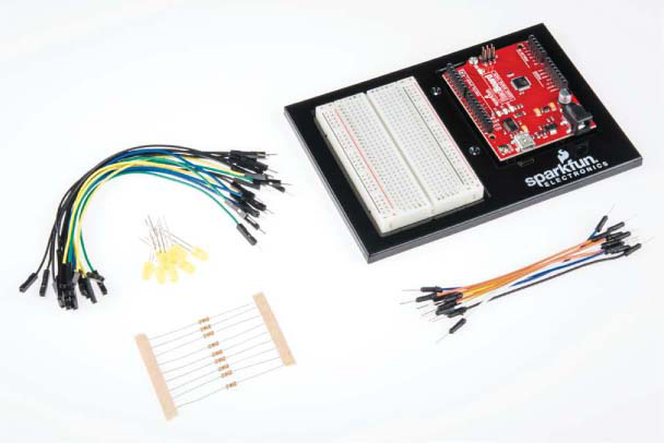
For this project, you’ll need a few more electronic components than you used in Project 2, specifically more LEDs. This project is simpler in terms of enclosure construction, however. The materials you’ll need are shown in Figures 3-2 and 3-3.
NOTE
In our project all the LEDs are the same color so the patterns are easier to see, but if you don’t have nine LEDs of the same color, you can mix them up.
Electronic Parts
• One SparkFun RedBoard (DEV-13975), Arduino Uno (DEV-11021), or any other Arduino-compatible board
• One USB Mini-B cable (CAB-11301 or your board’s USB cable; not shown)
• One solderless breadboard (PRT-12002)
• Nine LEDs, preferably of the same color (COM-10049 for a pack of 20 red and yellow LEDs)
• Nine 330 Ω resistors (COM-11507 for a pack of 20)
• Male-to-male jumper wires (PRT-11026)
• Male-to-female jumper wires (PRT-09140*)
• (Optional) One 4 AA battery holder (PRT-09835*; not shown)
NOTE
The parts marked with an asterisk (*) do not come with the standard SparkFun Inventor’s Kit but are available in the separate add-on kit.
FIGURE 3-2: Components for the Nine-Pixel Animation Machine
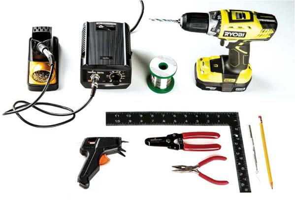
Other Materials and Tools
• Pencil
• Craft knife
• Metal ruler
• Wire cutters
• Glue (hot glue gun or craft glue)
• Graph paper (not shown)
• (Optional) Drill and a 3/16-inch drill bit
• (Optional) Soldering iron
• (Optional) Solder
• (Optional) Helping hands (not shown)
• Cardboard sheet (roughly 8 × 11 inches, or 20.5 × 30 cm; not shown)
• Enclosure template (see Figure 3-13 on page 83)
FIGURE 3-3: Recommended tools
BUILD THE NINE-PIXEL ANIMATION MACHINE PROTOTYPE
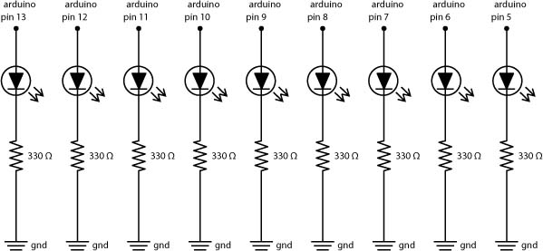
This simple pixel art display will teach you to manage lots of wires in one circuit, which is important as your circuits grow larger. First, you’ll use the breadboard to make sure the circuit works, test a sketch, and get comfortable with all of the jumper wires. (We’ll show you how to transfer the LEDs to a display housing in “Cardboard Construction” on page 83.) Notice that the circuit diagram in Figure 3-4 looks a lot like Figure 2-6 on page 43. That’s because this project uses the same LED circuit, but instead of just three LEDs, it uses nine LEDs, each of which is independently controlled by a pin on the Arduino.
FIGURE 3-4: Schematic diagram for the Nine-Pixel Animation Machine
In this section, you’ll use the breadboard to connect all nine LEDs to pins on the Arduino. With your components and jumper wires in hand, build the circuit in Figure 3-5 on your breadboard. If you want to practice building smaller LED circuits first, flip back to “Connect the Red LED to the Breadboard” on page 44 for a refresher.
FIGURE 3-5: Nine LEDs connected to the Arduino, with the pin 13 LED at the top and the pin 5 LED at the bottom
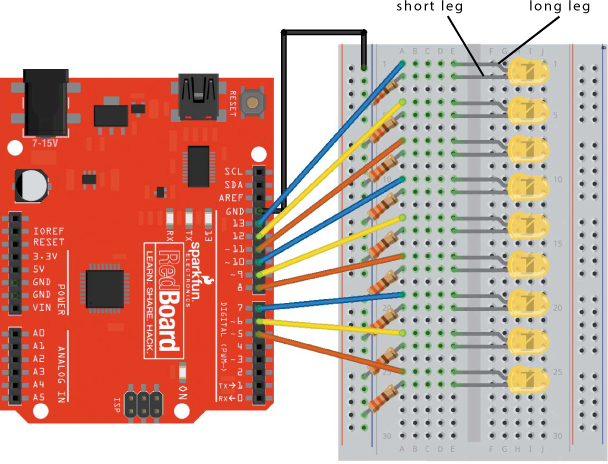
Wiring up nine LEDs can make for a cluttered breadboard. To keep your breadboard organized, connect the ground rail (–) on the left side of your breadboard to the GND pin on the Arduino first. That’s the black wire in Figure 3-5. Then, connect your first LED’s negative leg (the shorter one) to this ground rail through a 330 Ω resistor. In Figure 3-5, the long leg of the LED is in row 1, and the shorter leg is in row 2. Finally, connect the long leg of the LED to pin 13 with a jumper wire from pin 13 of the Arduino to row 1 of the breadboard. Connect the other eight LEDs to pins 12 through 5 in the same way. And remember: the LED’s short leg is its negative leg. As you’re building this circuit, make sure that the shorter leg of each LED is connected to the ground rail of the breadboard through a resistor. When you’re done, your circuit should resemble the circuit in Figure 3-6.
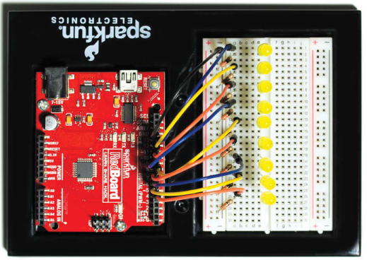
FIGURE 3-6: Final prototype circuit of nine LEDs connected to the Arduino, with the pin 13 LED at the top and the pin 5 LED at the bottom
Once you’ve wired the nine LEDs, open the Arduino IDE and plug the Arduino into your computer with the USB cable. If you uploaded a sketch to the Arduino in a previous project, you might see the LEDs light up as it runs the last sketch you uploaded. Now let’s take a look at how you’ll code up all nine of these LEDs.
PROGRAM THE NINE-PIXEL ANIMATION MACHINE
In previous projects, it’s been simple enough to use a bunch of digitalWrite() functions and delay() functions to control LEDs. But with nine LEDs, you’d have a really messy loop() function! Instead, you can write your own custom function to blink a single LED, and then use this function to control all the LEDs.
What Are Custom Functions?
The Arduino language has 60 or so built-in (or predefined) functions that make it easier for you to interact with hardware using simple, single-line instructions. The digitalWrite() and delay() functions are two examples. Behind the scenes, the digitalWrite() function consists of more than 20 lines of code. Most of that code is complex, but the digitalWrite() function is easy to understand.
Even when you understand a big sketch, typing 20 or more lines of code each time you want to turn an LED on or off is tedious and error prone. Arduino’s built-in functions cover common tasks, but when you need to do something specific to your sketch, you’ll want to write custom functions. Custom functions allow you to easily reuse code in other sketches, and they’ll make your loop() functions easier to read.
Write a Custom Function
You can use custom functions to teach the Arduino new commands. Your first test function will blink an LED on and then off again, using a modified version of the code in Listing 3-1.
LISTING 3-1: A simple sketch that blinks an LED
void setup()
{
pinMode(13, OUTPUT);
}
void loop()
{
digitalWrite(13, HIGH);
delay(1000);
digitalWrite(13, LOW);
delay(1000);
}
This code should look similar to the Blink example from Project 1 (Listing 1-1 on page 28). However, here we are using pin 13 explicitly instead of using the LED_BUILTIN system constant. This code turns the LED on, waits for a second, turns the LED off again, and then waits for another second before repeating. You’ll need to do this a lot in later projects, so we’ll show you how to put this code in a custom blink() function. To make your custom function as useful as possible, you’ll write it in a way that allows you to use any pin for any delay time.
First, open a new sketch, copy the code from Listing 3-1 into it, and save it. Then, define the blink() function below your setup() and loop() functions, as shown in Listing 3-2.
LISTING 3-2: A skeleton for a custom blink() function
➊void ➋blink(➌int pinNumber, int delayTime)
{
//custom function code goes here
}
This is just the skeleton of the function. Function definitions always specify the data type that the function will return first ➊. The blink() function asks the Arduino to perform a task without expecting any data back, so, just like the setup() and loop() functions, its data type is void.
Next comes the function’s name ➋, which in this case is blink. You can name Arduino functions almost anything you want, but they can’t start with a number or include any spaces or special characters. Also, to make sure the function’s purpose is clear when you’re reading over your sketch, we recommend using a name that’s descriptive and easy to remember.
After naming the function, define any parameters the function needs to work in parentheses ➌. To make blink() as reusable as possible, provide a pin number and a delay time as parameters. These allow you to specify which LED to blink and for how long. Each of the blink() function’s parameters is an int. Notice that defining parameters is similar to declaring variables. That’s because parameters are basically variables that can only be used inside the function.
Finally, a custom function has its own set of curly brackets, which enclose all of the code you want a call to the function to represent. For the blink() function, this is the set of digitalWrite() and delay() functions from Listing 3-1, as shown in Listing 3-3. Add the code inside the curly brackets to your blink() function now.
LISTING 3-3: Custom blink() function
void blink(int pinNumber, int delayTime)
{
digitalWrite(pinNumber, HIGH);
delay(delayTime);
digitalWrite(pinNumber, LOW);
delay(delayTime);
}
Notice that in the digitalWrite() and delay() function calls, the blink() function replaces the pin number 13 and the delay of 1000 ms with the pinNumber and delayTime parameters, respectively.
Use a Custom Function
Now you can use your custom function in place of the code in your loop() function, as in Listing 3-4.
LISTING 3-4: Complete sketch using the new custom blink() function
void setup()
{
pinMode(13, OUTPUT);
}
void loop()
{
blink(13, 1000);
}
void blink(int pinNumber, int delayTime)
{
digitalWrite(pinNumber, HIGH);
delay(delayTime);
digitalWrite(pinNumber, LOW);
delay(delayTime);
}
The modified loop() function calls the blink() function and passes it the pin number of the LED to blink (13) and the amount of time the light should stay on or off, in milliseconds (we suggest using 1000, for 1 second). That’s it! Doesn’t this code look a lot cleaner and clearer?
Upload this sketch to your Arduino, and the LED on pin 13 should blink. Congratulations! You just “taught” the Arduino what blink() means, and you condensed four lines of code into a single instruction.
But custom functions are just one key to this project. You’ll also want to plan some nine-pixel patterns ahead of time to make them easier to program, so let’s do that now.
TRY IT OUT: PLAY WITH PATTERNS
Before you finish the Nine-Pixel Animation Machine, spend some quality time with your more powerful blink() sketch. For example, change your loop() function as follows:
void loop()
{
blink(13, 100); //short 100 ms blink on pin 13
blink(13, 2000); //longer 2000 ms blink on pin 13
}
This makes the LED blink for 100 ms, followed by a longer blink of 2,000 ms. Try blinking the other LEDs to create your own patterns and sequences!
Design Your Artwork
Grab colored pencils and graph paper, and put on your artist’s hat! You’re going to make some pixel art to display on the Nine-Pixel Animation Machine.
Start by drawing several 3 × 3 grids, or print out a copy of the template shown in Figure 3-7, which you’ll find in this book’s resource files. These drawings don’t have to be perfect; you’re just sketching out a few ideas.
FIGURE 3-7: Blank grid planning template
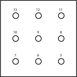
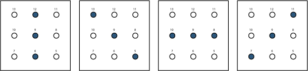
We numbered the pixels with 13 in the upper-left corner and 5 in the lower-right corner. These numbers correspond to the LED pin numbers on the Arduino; this is how you’ll control the LEDs in the Nine-Pixel Animation Machine. When your canvas is ready, get creative: fill in the pixels to make your own patterns. Figure 3-8 shows some examples that we came up with during a department meeting . . . don’t tell our boss!
FIGURE 3-8: Some pixel pattern examples
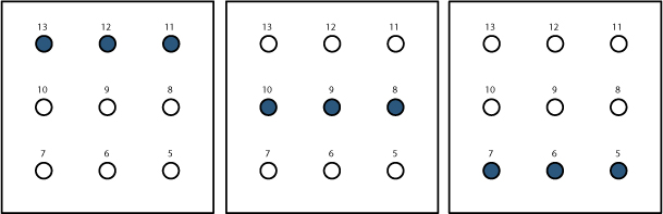
When you show these patterns and shapes in sequence, you can create animations! First, we’ll teach you to program two simple shapes, and then we’ll tackle a complete animation.
The Test Sketch
Create a new sketch in the Arduino IDE, and add the setup() and loop() functions in Listing 3-5.
LISTING 3-5: setup() function for the Nine-Pixel Animation Machine
//LED array is set up in this arrangement:
// 13 ---- 12 ---- 11
// 10 ---- 9 ----- 8
// 7 ---- 6 ----- 5
void setup()
{
pinMode(13, OUTPUT);
pinMode(12, OUTPUT);
pinMode(11, OUTPUT);
pinMode(10, OUTPUT);
pinMode(9, OUTPUT);
pinMode(8, OUTPUT);
pinMode(7, OUTPUT);
pinMode(6, OUTPUT);
pinMode(5, OUTPUT);
}
void loop()
{
}
NOTE
We also suggest adding a comment with a diagram of the LED placement. Describing the circuit you’re writing code for in the sketch will help others re-create it and will remind you of the structure you’re working with as you develop your code.
This project uses nine LEDs on nine digital GPIO pins (13 through 5), so this setup() function has nine pinMode() functions. They’re all set as OUTPUT since they’re controlling LEDs.
Write a Function to Draw an X
With the pinMode() functions in place, look at the shapes you drew by hand and pay attention to the numbers; they’ll help you write your custom function. Figure 3-9 shows an example to test with—a simple X pattern.
FIGURE 3-9: A nine-pixel X
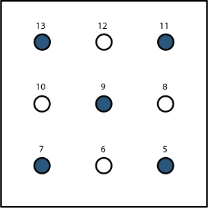
The X pattern in Figure 3-9 translates to the set of digitalWrite() functions in Listing 3-6.
LISTING 3-6: Code for displaying an X on the nine LEDs
digitalWrite(13, HIGH);
digitalWrite(12, LOW);
digitalWrite(11, HIGH);
digitalWrite(10, LOW);
digitalWrite(9, HIGH);
digitalWrite(8, LOW);
digitalWrite(7, HIGH);
digitalWrite(6, LOW);
digitalWrite(5, HIGH);
These digitalWrite() function calls turn on only the LEDs on the grid’s diagonals and turn off the rest. But drawing a single X takes nine lines of code! Instead of writing all of this out by hand every time, you can create a custom function to execute all of these calls with just one line of code.
Below the curly brackets of the loop() function, create a custom function named xChar() with the code in Listing 3-7.
LISTING 3-7: The xChar() custom function
void xChar()
{
digitalWrite(13, HIGH);
digitalWrite(12, LOW);
digitalWrite(11, HIGH);
digitalWrite(10, LOW);
digitalWrite(9, HIGH);
digitalWrite(8, LOW);
digitalWrite(7, HIGH);
digitalWrite(6, LOW);
digitalWrite(5, HIGH);
}
We named this custom function xChar() because it displays an X character. This function won’t return anything, so its data type is void. Since the digitalWrite() calls from Listing 3-6 are inside this single custom function, you can keep your loop() code simple. Call the function xChar() inside your existing loop(), as shown in Listing 3-8.
LISTING 3-8: loop() function with xChar() function call
void loop()
{
xChar();
}
This is a small step, but it’s very important. If you forget to actually call your custom function, its code will never run, and you’ll never display your X.
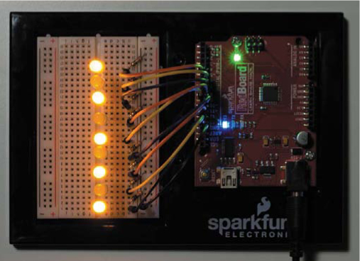
Upload this sketch to your Arduino now. Your LEDs are still in a vertical line rather than a grid, but your sketch can still help you test that you’ve got everything wired and coded correctly. Instead of an X, you should see every other LED turn on, starting at the top, as shown in Figure 3-10. If the LEDs don’t light up as expected, double-check your wiring against the diagram in Figure 3-5 on page 71, and check your digitalWrite() functions to make sure they’re all correct as well.
When you can see the right pattern, read on to create a second character.
FIGURE 3-10: Prototype and correct sequence for an X
Write a Function to Draw an O
Next, you’ll create an O like the one in Figure 3-11 to go with the X.
FIGURE 3-11: A nine-pixel O
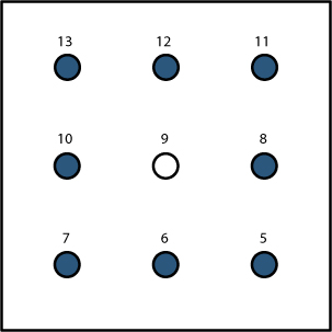
Pro tip: you can work smarter rather than harder here. Copy the entire xChar() function, paste the copy after the last curly bracket in xChar(), change its name to oChar(), and tweak it to look like Listing 3-9.
LISTING 3-9: The oChar() custom function
void oChar()
{
digitalWrite(13, HIGH);
digitalWrite(12, HIGH);
digitalWrite(11, HIGH);
digitalWrite(10, HIGH);
digitalWrite(9, LOW);
digitalWrite(8, HIGH);
digitalWrite(7, HIGH);
digitalWrite(6, HIGH);
digitalWrite(5, HIGH);
}
The only difference between xChar() and oChar() is which LEDs are turned on and which are turned off. Whereas xChar() turns on alternating LEDs, oChar() turns on every LED except the center one.
TRY IT OUT: WRITE A CUSTOM FUNCTION FOR YOUR OWN IMAGE
We showed you how to write functions to draw an X and an O, but we’re sure you have your own lovely pixel art images in mind. Create a function that will blink out the patterns you made, and hang on to it for when you’re done building the Nine-Pixel Animation Machine.
Display the X and the O
The goal now is to show an X character for a bit, then show an O character, and finally go back to the X. To show each character for a set time, you can add the oChar() function to your existing loop and slow the loop down with delay() calls. Update your sketch so that it looks like Listing 3-10.
LISTING 3-10: The loop() looks similar to the one in the Blink sketch but uses xChar() and oChar() instead of digitalWrite().
//LED array is set up in this arrangement:
// 13 ---- 12 ---- 11
// 10 ---- 9 ----- 8
// 7 ---- 6 ----- 5
void setup()
{
pinMode(13, OUTPUT);
pinMode(12, OUTPUT);
pinMode(11, OUTPUT);
pinMode(10, OUTPUT);
pinMode(9, OUTPUT);
pinMode(8, OUTPUT);
pinMode(7, OUTPUT);
pinMode(6, OUTPUT);
pinMode(5, OUTPUT);
}
void loop()
{
//blink between x and o characters
xChar();
delay(500);
oChar();
delay(500);
}
void xChar()
{
digitalWrite(13, HIGH);
digitalWrite(12, LOW);
digitalWrite(11, HIGH);
digitalWrite(10, LOW);
digitalWrite(9, HIGH);
digitalWrite(8, LOW);
digitalWrite(7, HIGH);
digitalWrite(6, LOW);
digitalWrite(5, HIGH);
}
void oChar()
{
digitalWrite(13, HIGH);
digitalWrite(12, HIGH);
digitalWrite(11, HIGH);
digitalWrite(10, HIGH);
digitalWrite(9, LOW);
digitalWrite(8, HIGH);
digitalWrite(7, HIGH);
digitalWrite(6, HIGH);
digitalWrite(5, HIGH);
}
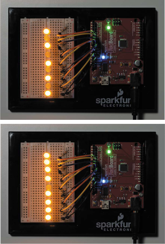
This loop displays an X for 500 ms and then switches to an O for 500 ms. Upload the updated sketch to your Arduino, and run it to see how it works. Every LED except the middle one lights up when oChar() is called. Figure 3-12shows what you’ll see as the LEDs blink.
FIGURE 3-12: Switching between two patterns
Save your sketch now, because you’ll build on it later. But as long as the LEDs in this circuit are on the breadboard, they won’t display any recognizable picture. So next, we’ll show you how to make the display to see the Nine-Pixel Animation Machine in all its tiny glory.
BUILD THE NINE-PIXEL ANIMATION MACHINE ENCLOSURE
The enclosure for this project is simply a cardboard display with holes for LEDs. There’s wiring to do as well, but once that’s done, you’ll be able to make all kinds of pixel art.
Cardboard Construction
Find a sheet of cardboard that is clean and free of creases and bends. Our designs are based around cardboard about 1/8 inch thick, but you can use any similar board or panel materials. Some materials will be easier to cut than others, so pick yours based on the tools you have.
Cut Out the Parts
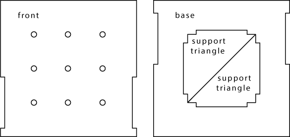
Open the template shown in Figure 3-13 in this book’s resource files (https://www.nostarch.com/arduinoinventor/) and trace it onto your cardboard. Try to line your templates up with the edge of the cardboard to make cutting easier.
FIGURE 3-13: Enclosure template for the Nine-Pixel Animation Machine (not full size)
Once you’ve traced your pieces, cut them out. We highly recommend using a sharp craft knife and a metal ruler to get clean edges for your project. Remember craft knife safety: always pull (don’t push) the blade, and make multiple passes rather than digging in deeply on your first go.
After cutting your cardboard parts, make the LED holes in the front piece. You can drill them as shown in Figure 3-14, punch them with a hole punch, or even poke them out with a pencil. Just be sure to have a free LED on hand to test the size of each hole for a snug fit. If the holes are a little too large and you don’t mind making the LEDs a permanent feature of the project, you can hot glue them in.
FIGURE 3-14: Drilling holes for LEDs. Use caution when drilling or ask an adult for help.

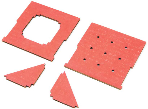
You should have four pieces cut out, as shown in Figure 3-15. The base has the big hole in the middle; use its center piece to cut out two triangles to use as support braces. These triangles have tabs that fit into slots connecting the bottom piece to the front. Before assembling the parts, however, add labels so that you can keep your LEDs straight when you wire up your circuit.
FIGURE 3-15: Cardboard pieces for the enclosure
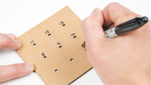
Label the LED Holes
Flip the front cardboard piece over, and number the LEDs so you have a connection guide. Start with pin 13 in the top right and count down as you go left, as shown in Figure 3-16. You should finish with 5 in the lower-left corner.
FIGURE 3-16: Labeling the back side of the LED grid
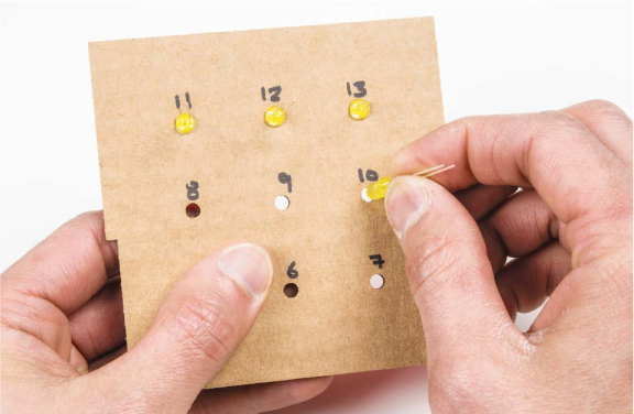
Add the LEDs
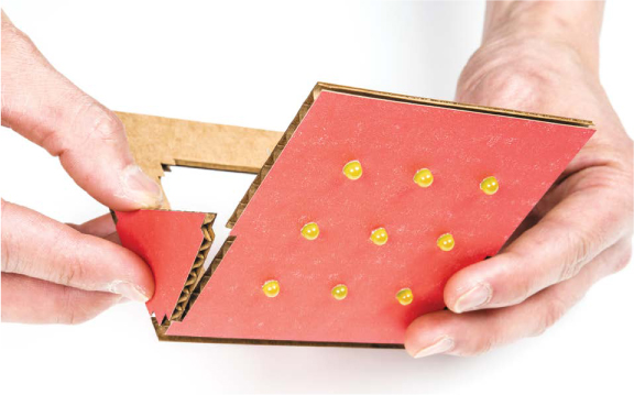
With the cardboard flat, insert the nine LEDs through from the back side. You can reuse the LEDs from your breadboard prototype or grab new ones. As you insert the LEDs, keep them aligned with the long leg on the right side to make things easier when you start wiring them to the Arduino again. You want the LEDs to fit snugly, as shown in Figure 3-17. If the hole is too big, you can add a dab of hot glue to secure it (but, again, keep in mind that you won’t be able to reuse the LEDs afterward).
FIGURE 3-17: Inserting the LEDs
Assemble the Parts
Now, gather the four pieces of cardboard to be assembled. You’ll probably need craft glue or a hot glue gun to secure all of the pieces together.
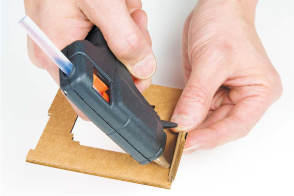
First, glue one of the triangles to the base to support the front plate, as shown in Figure 3-18. See Figure 3-19 for the orientation of the support triangles. Repeat this process for the other triangle piece. Give the glue some time to dry before moving on.
FIGURE 3-18: Adding support triangles to the base
With the support triangles in place, glue the front to the base. The front should fit snugly onto the tabs of the support triangles and sit on top of the base cardboard, as shown in Figure 3-19. For extra strength, you may also want to add hot glue along the inside edges where the front plate connects to the base and support triangles.
FIGURE 3-19: Adding the final piece of the project—the front
With the cardboard construction part of this project done, it’s time to wire the circuit.
Connect the Electronics
There are a lot of wires in this project, so we’ll take it one step at a time. You’ll reuse the breadboard prototype circuit you built earlier in this chapter and simply use jumper wires to connect the nine LEDs to the Arduino.
There are two ways to approach this part of the project: the nonpermanent way, which uses male-to-female jumper wires, and the permanent way, which involves soldering. We’ll cover the nonpermanent approach, but if you do want to solder the LEDs to jumper wires, refer to “How to Solder” on page 302 for a brief lesson before you attempt that.
If the LED legs are too long, you can snip them before attaching the jumper wires, but pay attention to which leg is positive (the long leg) and which is negative. Leave the positive leg a little longer so that you can still tell which leg is which; you could also draw a dot on the back of the box. Be sure to wear eye protection, too—when you’re trimming the legs, the little wire pieces can fly up in the air and toward your eyes!
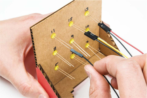
Connect the female end of each jumper wire to one of the nine LEDs on the front plate. To keep things organized, use black wires to designate the negative side, and connect these to the shorter leg of the LED, as shown in Figure 3-20. You can use any color for the positive side of each LED.
FIGURE 3-20: Connecting the LEDs with male-to-female jumper wires
Once all nine LEDs are connected to male-to-female wires, connect the other end of each jumper wire to the breadboard, following the pin labels on the back side of your project. If you left the LEDs in the breadboard, remove those first, and simply plug the jumper wires into them as shown in Figure 3-21.
FIGURE 3-21: Nine LEDs connected to the breadboard with male-to-female jumper wires
Each wire connected to the negative leg of an LED (each black wire) connects to a resistor that is connected to the ground rail. Each positive wire connects to the Arduino pin written on the back of your LED array.
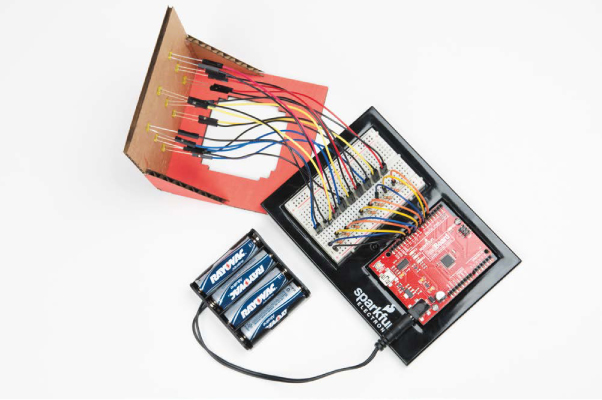
Once you’ve added all nine LEDs to the front of your display and completed your wiring, plug your Arduino into your computer with a USB cable. If everything is wired correctly, your display will show an alternating X and Opattern. If you have a battery pack, you can connect it as shown in Figure 3-22.
If the test images don’t show properly, double-check that the LEDs are plugged into the correct Arduino pins. When you see the correct patterns, take a moment to bask in the glory of your new pixel art display, but don’t stop here! When you’re ready, try making a more complicated animation.
FIGURE 3-22: The final display with cycling X and O characters
CREATE AN LED ANIMATION
Your monitor can display any image you can draw on a 3×3 grid. An animation is just a series of images shown sequentially, so if you show a bunch of 3×3 images in a row, you’ll have a pixel art animation. We’ll show you how to design and display a spinning line.
Plan the Animation Sequence
Let’s begin by translating a spinning line into a series of images. We started with a vertical line and rotated it around the display in four separate images, as shown in Figure 3-23.
FIGURE 3-23: Image progression of a spinning line
Save your program from Listing 3-10, and then create a new sketch. Add the setup() and loop() functions in Listing 3-11.
LISTING 3-11: The setup() code for all nine LEDs
void setup()
{
pinMode(13, OUTPUT);
pinMode(12, OUTPUT);
pinMode(11, OUTPUT);
pinMode(10, OUTPUT);
pinMode(9, OUTPUT);
pinMode(8, OUTPUT);
pinMode(7, OUTPUT);
pinMode(6, OUTPUT);
pinMode(5, OUTPUT);
}
void loop()
{
//animation function call will go here
}
//custom functions to show frames will go here
Since you’re using the same LEDs you were in the X and O sketch, you can just copy the code from there into your new sketch.
Write Custom Functions
Now, create a custom function for each image of your animation. This animation has four frames, so you’ll need four functions. Add the functions in Listing 3-12 to your sketch, after the closing bracket in the loop() function.
LISTING 3-12: Custom functions to draw a spinning line
➊ void verticalLine()
{
digitalWrite(13, LOW);
digitalWrite(12, HIGH);
digitalWrite(11, LOW);
digitalWrite(10, LOW);
digitalWrite(9, HIGH);
digitalWrite(8, LOW);
digitalWrite(7, LOW);
digitalWrite(6, HIGH);
digitalWrite(5, LOW);
}
➋ void topLeftDiagonal()
{
digitalWrite(13, HIGH);
digitalWrite(12, LOW);
digitalWrite(11, LOW);
digitalWrite(10, LOW);
digitalWrite(9, HIGH);
digitalWrite(8, LOW);
digitalWrite(7, LOW);
digitalWrite(6, LOW);
digitalWrite(5, HIGH);
}
➌ void horizontalLine()
{
digitalWrite(13, LOW);
digitalWrite(12, LOW);
digitalWrite(11, LOW);
digitalWrite(10, HIGH);
digitalWrite(9, HIGH);
digitalWrite(8, HIGH);
digitalWrite(7, LOW);
digitalWrite(6, LOW);
digitalWrite(5, LOW);
}
➍ void topRightDiagonal()
{
digitalWrite(13, LOW);
digitalWrite(12, LOW);
digitalWrite(11, HIGH);
digitalWrite(10, LOW);
digitalWrite(9, HIGH);
digitalWrite(8, LOW);
digitalWrite(7, HIGH);
digitalWrite(6, LOW);
digitalWrite(5, LOW);
}
The verticalLine() function ➊ shows the first image in Figure 3-23, the topLeftDiagonal() function ➋ shows the second image, the horizontalLine() function ➌ shows the third, and the topRightDiagonal() function ➍ shows the last. As with your previous custom function, these custom functions have the void data type, since they won’t return a value.
Custom functions can call other custom functions, too, so let’s call the four line functions inside a single spinningLine() function. Add the following code to your sketch, after the closing bracket in the topRightDiagonal() function.
void spinningLine(int delayTime)
{
verticalLine();
delay(delayTime);
topLeftDiagonal();
delay(delayTime);
horizontalLine();
delay(delayTime);
topRightDiagonal();
delay(delayTime);
}
This code shows a vertical line, a diagonal line, a horizontal line, and another diagonal line, with a delay after each line. Now, all you have to do is call spinningLine() inside the loop() function.
NOTE
You’ll find a complete listing of this code in the resource files at https://nostarch.com/arduinoinventor/.
Tweak Your loop() Function
Add a call to your custom function inside your loop() function, as in Listing 3-13. Remember that you still need to have all of those pinMode() commands in your setup() function.
LISTING 3-13: Completed loop() function with the new custom function call spinningLine(200);
void loop()
{
spinningLine(200);
}
Once you add the function and pass it a delay time parameter (the code uses 200), upload your sketch to your Arduino. You’ll see a rotating line on your display. With this knowledge of sequencing LEDs and custom functions, you can make your own nine-pixel animation!
GOING FURTHER
Custom functions will be useful when you want to reuse code later or organize your code. To take this project further, try designing more elaborate animations; you could even come up with your own alphabet and use your monitor to display a secret message.
Hack
To take this project further, start by creating more elaborate animations. As you work through the next few projects, look for ways to incorporate your monitor—for example, maybe you could use a sensor to control an animation speed or display a sensor value in some interesting ways. Download a blank design template at https://www.nostarch.com/arduinoinventor/.
Modify
You’ve learned how to control a number of electronic components by using digital pins and custom functions. Try replacing your individual LEDs with different components. We suggest a seven-segment display, as shown in Figure 3-24.
FIGURE 3-24: A single seven-segment display
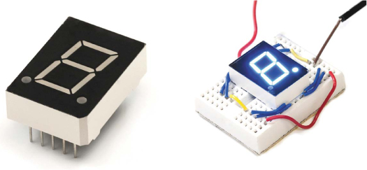
Each segment is an LED that you can control. There are seven individual segments (plus the decimal points), as shown in Figure 3-25, and by turning specific segments on and off, you can make numbers and most letters of the English language.
FIGURE 3-25: Illustration of the seven individual segments and the decimal point with a corresponding wiring diagram
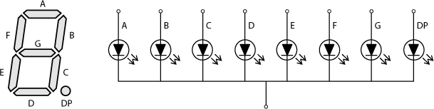
You can control one of these displays the same way you control the Nine-Pixel Animation Machine: just create custom functions for each number. For a challenge, create a single function that lets you pass a number to display to it.
All materials on the site are licensed Creative Commons Attribution-Sharealike 3.0 Unported CC BY-SA 3.0 & GNU Free Documentation License (GFDL)
If you are the copyright holder of any material contained on our site and intend to remove it, please contact our site administrator for approval.
© 2016-2026 All site design rights belong to S.Y.A.