The Arduino Inventor's Guide (2017)
4 Reaction Timer
An average human reacts to a visual stimulus, like a light turning on, in about 215 milliseconds. This is the time it takes for a signal you see with your eyes to travel to your brain and out to your limbs to respond. The reaction timer is a great project to demonstrate this time delay, and it also makes for a fun game! How fast are you and your friends?
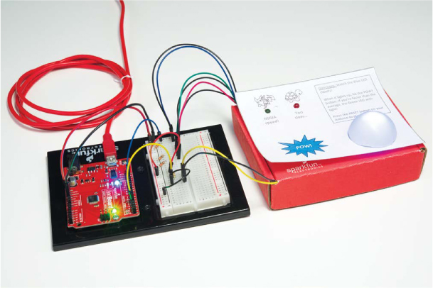
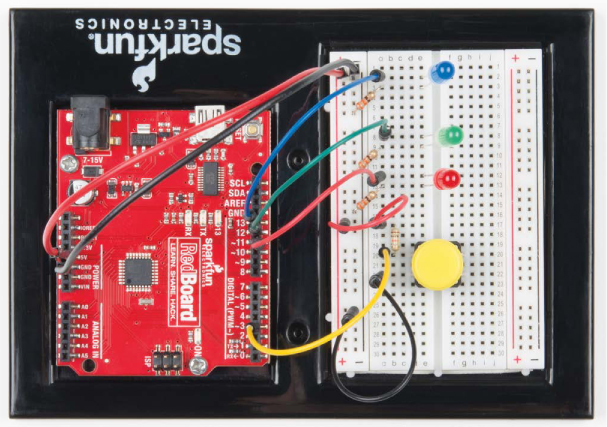
In this chapter, you’ll learn how to build your own reaction timer using Arduino. The full project is shown in Figure 4-1. The concept behind it is simple: the Arduino will turn on an LED, start a timer, and wait until you press a button. When you see the LED turn on, you press the button as quickly as you can, and the Arduino will report back to your computer the time between the light coming on and you pressing the button. The Arduino has a 16 MHz clock, which means that it can process 16 million instructions per second! That’s fast, and it makes the Arduino perfect for this project.
FIGURE 4-1: The completed Reaction Timer project
MATERIALS TO GATHER
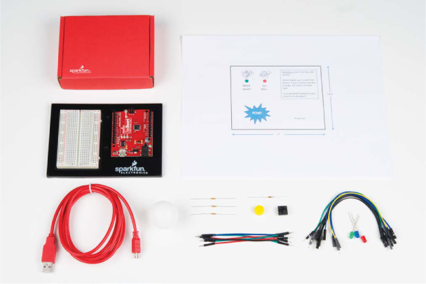
Like the previous projects in this book, the Reaction Timer uses LEDs, resistors, wires, and an Arduino. Unlike other projects, this one also includes a button to make the game interactive, and to make it look spiffy we suggest a custom cardboard enclosure. Figures 4-2 and 4-3 show the parts and materials you’ll need for this project.
Electronic Parts
• One SparkFun RedBoard (DEV-13975), Arduino Uno (DEV-11021), or any other Arduino-compatible board
• One USB Mini-B cable (CAB-11301 or your board’s USB cable)
• One solderless breadboard (PRT-12002)
• One red LED, one blue LED, and one green LED (COM-12062)
• Three 330 Ω resistors (COM-08377, or COM-11507 for a pack of 20)
• One 10 kΩ resistor (COM-08374, or COM-11508 for a pack of 20)
• One push button (COM-10302)
• Male-to-male jumper wires (PRT-11026)
• Male-to-female jumper wires (PRT-09140*)
NOTE
The parts marked with an asterisk (*) do not come with the standard SparkFun Inventor’s Kit but are available in the separate add-on kit.
FIGURE 4-2: Components and materials for the Reaction Timer
Other Materials and Tools
• Pencil
• Craft knife
• Metal ruler
• Glue (hot glue gun or craft glue)
• (Optional) Drill and 3/16-inch and 5/16-inch drill bits
• (Optional) Wire cutters (not shown)
• Cardboard (about 12 inches square) or a cardboard box
• Enclosure template (see Figure 4-16 on page 115)
• (Optional) Ping-pong ball
FIGURE 4-3: Recommended tools

NEW COMPONENT: THE PUSH BUTTON
This project revolves around two components: an LED and a button. The button switch is an input to an Arduino pin, which means that the sketch can react to a change in the voltage on that pin. Inputs like buttons let you create circuits that people can interact with.
How Push Buttons Work
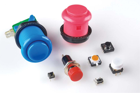
There are many different kinds of push buttons, but they all work in a similar manner. A push button is really an electrical switch. Push buttons like the ones in Figure 4-4 are small, spring-loaded devices that connect two sides together electrically for as long as you apply pressure, like the keys on your keyboard. And they’re everywhere—in remote controls, garage door openers, coffee makers, radios, game controllers, and so much more!
FIGURE 4-4: A variety of push buttons
These nifty input devices are really simple on the inside. Figure 4-5 shows the schematics for both a push button and a switch.
FIGURE 4-5: Schematic drawings for a push button and a switch
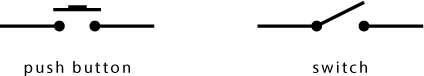
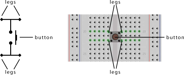
When you flip a switch on, a piece of metal inside closes the gap between two contacts, like a gate. When you press a push button, metal pushes straight down to bridge that gap. Find a push button in your supplies for this project and examine it. Even though the schematic symbol in Figure 4-5 shows only two contacts, most standard push buttons for breadboards have four legs. Figure 4-6 shows a more accurate illustration of the contacts inside, along with how a button like that might look on the breadboard. When you plug one in, the legs should straddle the ditch in the middle of the breadboard.
FIGURE 4-6: Push button schematic and button correctly placed on a breadboard with legs straddling the ditch
Push buttons are fantastic inputs in projects, because everyone knows how they work. Push buttons are also pretty simple to connect in a circuit with an Arduino. Let’s look at how that works.
Using Resistors with Push Buttons
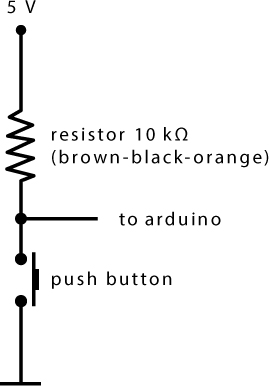
To use any button as an input to an Arduino, you’ll need to use a pull-up resistor circuit like the one in Figure 4-7. A pull-up resistor connects to a power source on one side and to an input component (like a button) on the other. The part of a circuit that needs to detect input is connected at the intersection of the resistor and the button.
In the configuration shown in Figure 4-7, the resistor to 5 V pulls the Arduino pin’s default voltage up to 5 V, which is considered HIGH. When the button is pushed, a path is created between the Arduino pin and ground, and the Arduino pin reads a LOW voltage. This works because current always flows along the path of least resistance: when the button isn’t pressed, the Arduino pin 10 kΩ resistor is the only path the current can access, but when the button is pressed, it offers a path with effectively zero resistance.
FIGURE 4-7: Pull-up resistor and push button circuit
BUILD THE REACTION TIMER PROTOTYPE
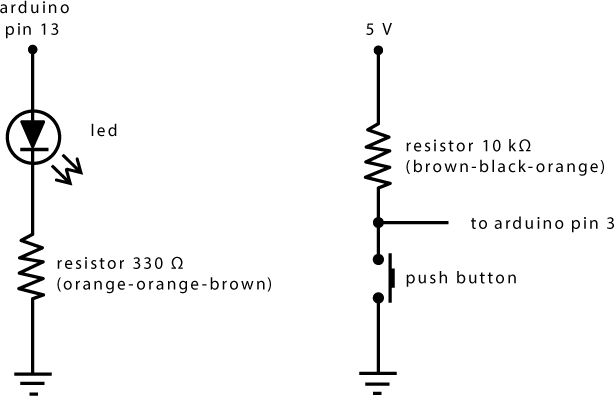
The Reaction Timer combines an LED circuit similar to the ones in previous projects with the button circuit from Figure 4-7 to make the supercircuit in Figure 4-8, which lights an LED and detects button presses.
FIGURE 4-8: Schematic diagram for the Reaction Timer prototype
Take out your breadboard and wire up a single LED and a button, as shown in Figures 4-9 and 4-10. You’ll use this prototype to test your code before building the final Reaction Timer.
FIGURE 4-9: Wiring diagram for the Reaction Timer circuit
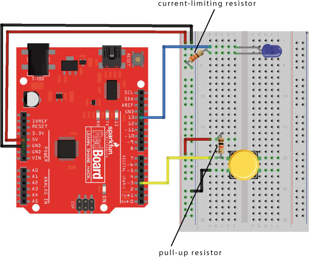
FIGURE 4-10: Final prototype circuit of the Reaction Timer with a single button and a single LED
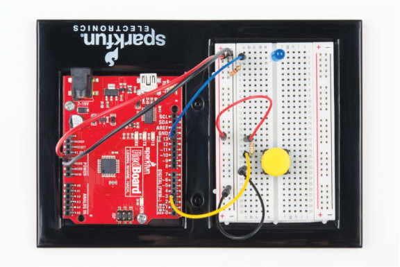
As you connect this circuit, note the two different resistance values: 330 Ω for the LED and 10 kΩ for the push button. (See “Resistors and Bands” on page 308 for details on how to determine the value of a resistor from its color bands.) The resistor on the LED is a current-limiting resistor and should be tied to ground, while the resistor on the push button is a pull-up resistor connecting pin 3 to 5 V. But your circuit can’t do anything without the code, so let’s look at that now.
PROGRAM THE REACTION TIMER
As your sketches and circuits become more complex, you’ll find it helpful to organize your thoughts by listing each action you want the Arduino to take, in the order you want it to happen. Some programmers refer to a list like this as pseudocode. Here’s our pseudocode for the Reaction Timer:
1. Wait a random amount of time before turning on the LED (to prevent predicting/gaming the Reaction Timer).
2. Turn on the LED.
3. Record the starting time.
4. Start a timer and wait for a button press.
5. When the button is pressed, calculate the reaction time as the timer value minus the starting time.
6. Report the time back.
Pretty simple, right? Let’s open up Arduino and look at the sketch.
Write the setup() Function
Open a new sketch and type the initialization and the setup() code shown in Listing 4-1.
LISTING 4-1: setup() and initialization code for the Reaction Timer
➊ unsigned int waitTime; //random wait time before
//turning on LED
unsigned int startTime; //zero reference time
unsigned int reactTime; //calculated reaction time
void setup()
{
➋ Serial.begin(9600); //sets up serial
//communication
pinMode(13, OUTPUT); //sets pin 13 as an OUTPUT for the
//stimulus LED
➌ pinMode(3, INPUT); //sets pin 3 as an INPUT for the
//button
}
NOTE
The unsigned int data type can hold values from 0 to 65,535 (216 – 1).
First, the namespace defines three unsigned int variables ➊ to store the waitTime, startTime, and reactTime values.
Next comes the setup() function, which has a new instruction: Serial.begin(9600) ➋. Make sure to capitalize Serial and leave no spaces between Serial, the period, and begin. This instruction is a little different from previous commands because it has a period that divides the object and the method. An object is a concept used in computer programming that is similar to a special type of variable that can have different functions or actions. Here Serial is the name of the object we’re using. The functions that an object can perform are called methods. The begin() method initializes or begins serial communication between your Arduino and your computer, which allows the Arduino to send and receive data through the USB cable. For this command, the number in the parentheses, 9600, sets the communication rate to 9,600 bits per second (or baud). The Arduino will use serial communication to report your reaction time back to your computer. The Serial object has many other methods, which we’ll introduce throughout this book, to handle data between the computer and the Arduino.
Finally, you’ll set up your pins. This project uses a single LED on pin 13 to indicate when to press the button, so you once again use pin 13 as an OUTPUT using the pinMode() function. Then set pin 3 with the pinMode() function ➌using the INPUT keyword. You use INPUT here because Arduino needs to be able to detect button presses, not output to the button.
Write the loop() Function
Now let’s write the loop() part of the sketch. Enter the code in Listing 4-2 after your setup() function.
LISTING 4-2: The loop() function for the Reaction Timer
void loop()
{
//prints the challenge instructions
➊ Serial.println("When the LED turns on, push the button!");
Serial.println("Now, watch the LED. Ready?");
➋ waitTime = random(2000, 4000); //random wait time
//from 2000 to 4000 ms
➌ delay(waitTime); //delay random wait time
//turn on the LED!
digitalWrite(13, HIGH);
startTime = ➍millis(); //set zero time reference
//loop to wait until button is pressed
➎ while(digitalRead(3) == HIGH)
{
}
➏ reactTime = millis() - startTime; //calculation of
//reaction time
digitalWrite(13, LOW); //turn off LED!
//display information to Serial Monitor
➐ Serial.print("Nice job! Your reaction time was ");
➑ Serial.print(reactTime);
➒ Serial.println(" milliseconds");
delay(1000); //short delay before starting again
}
First, this code uses the Serial.println() method ➊ to show a message prompt explaining how to play the game. The println() method sends text to the computer and adds a newline character to move the cursor down one line. When this method is called, any text between quotation marks (" ") is displayed on the Arduino IDE’s Serial Monitor. The Serial Monitor is like a simple chat window, or terminal, that allows you to send and receive data between the Arduino and your computer. You can open the Serial Monitor by clicking the magnifying glass button in the top-right corner of the Arduino IDE (shown in Figure 4-11), by clicking Tools ▸ Serial Monitor, or by using the hotkey CTRL-SHIFT-M.
FIGURE 4-11: Opening the Serial Monitor through the Arduino IDE
![]()
We’ll look at the Serial Monitor in just a moment.
Generate the Delay Time
To make the Reaction Timer less predictable, the sketch calls the random() function ➋ to generate a random waitTime. The random() function takes a minimum value and a maximum value as arguments and returns a pseudorandom number (a number that appears to be random but isn’t; this is explained in more detail in “Try It Out: Make waitTime More Random” on page 109). In this example, the waitTime variable is set to a “random” number between 2,000 and 4,000 and is passed to delay() ➌ before the LED turns on. This prevents you and your friends from predicting when to press the button.
When the LED turns on, a call to the millis() function ➍ captures the starting time. The millis() function checks the Arduino’s internal timer and returns the number of milliseconds since the Arduino was turned on or reset. The millis() function is handy for any Arduino project that involves timing.
Check the Button with a while() Loop
After fetching the start time, the sketch uses a while() loop ➎ to wait for a button press. In Arduino, as in many other programming languages, a while() loop runs the code inside its curly brackets as long as the expression between its parentheses is true. In this case, the expression is
digitalRead(3) == HIGH
The digitalRead() command reads the voltage on the pin specified between the parentheses and returns a value of HIGH or LOW depending on if it sees 5 V or GND. This call checks the voltage on pin 3. Remember that pull-up resistor on the push button? The button’s normal state is open, and the pin defaults to HIGH until you press the button to close the circuit. When you press the button, pin 3 connects to ground, and the state becomes LOW. The double equal sign (==) checks equality. (See “Logical Comparison Operators” on page 106.)
As long as the button isn’t pressed, the expression is true, and the while() loop should repeat, preventing the sketch from executing any code after. Notice, however, that there’s no actual code inside the loop. This is referred to as a holding or blocking loop, and rather than executing any code itself, it just prevents other code from executing. When the button is pressed, the expression becomes false, and the sketch proceeds.
Calculate and Display the Reaction Time
Next, the sketch computes the reaction time ➏ by subtracting the startTime from the current timer value, which is fetched with the millis() command.
As a final step, the LEDs are turned off, and the reactTime value is printed to the serial communication line. To make the information more readable, the sketch prints the string "Nice job! Your reaction time was " to the Serial Monitor using the print() method ➐ of the Serial object. This method sends the text between the quotation marks and doesn’t move the cursor to a new line. In fact, it keeps the cursor on the same line so that you can append more information, like the actual reaction time, which is added at ➑ with Serial.print(reactTime);. The sentence is finished with a call to the println() method ➒, which prints the string " milliseconds" and then moves the cursor to a new line.
LOGICAL COMPARISON OPERATORS
Logical comparison operators perform operations that test one value against another value. For example, the double equal sign (==) compares two values to see whether they are equal. A logical operation can return only one of two values: true, meaning the comparison evaluates correctly, or false, meaning it doesn’t evaluate correctly. In Arduino, there are many ways to compare two values, and all of the operators are listed in the following table:
|
OPERATOR |
COMPARISON |
|
== |
Equal to |
|
!= |
Not equal to |
|
> |
Greater than |
|
>= |
Greater than or equal to |
|
< |
Less than |
|
<= |
Less than or equal to |
For example, if you enter 2 == 4 in the Arduino IDE, it will return false, because two is not equal to four. However, if you enter 2 <= 4 in the Arduino IDE, it will return true, because two is less than or equal to four. In sketches, comparison operators are often used with if() or while() statements to run a certain block of code based on a certain condition. For example, the while() loop in Listing 4-2 says, “while digitalRead(3) == HIGH is true, repeat the holding loop; otherwise, skip to the next bit of code.”
A common bug is to mistakenly use a single equal sign when working with comparisons. Remember: a single equal sign sets a variable, whereas the double equal sign compares the two values.
You’ll use comparison operators more and more as you start to evaluate data your Arduino gathers from various sensors and inputs, and we’ll use some of them later in this chapter, too.
Notice that every character must be explicitly printed, including any spaces you want between numbers or characters. You can use the print() and println() methods, as in this example, to combine, format, or organize text that you display in the Serial Monitor.
The final line of code in the loop() function is a short delay() function to pause the sketch before it loops back and starts the Reaction Timer again.
SPECIAL COMMAND CHARACTERS
When printing data or text, you must represent every individual character, including spaces, and every formatting command in your code. There’s a set of reserved characters, called escape sequences, to indicate special formatting. For example, \n moves the cursor to a new line; so, Serial.print("Hello Arduino!\n"); is equivalent to Serial.println("Hello Arduino!");.
You can use escape sequences in your print statements to add formatting or other special characters to your text. The following table lists a handful of useful escape sequences.
|
ESCAPE SEQUENCE |
RESULT |
|
\t |
Tab |
|
\n |
New line |
|
\' |
Single quotation mark |
|
\" |
Double quotation mark |
|
\xhh |
ASCII character, where hh is a hexadecimal number |
Test the Reaction Timer Sketch
That’s all the code you need to test your Reaction Timer game circuit! Save your sketch, compile it, and upload it to your Arduino now. To see the data that your sketch sends on the serial communication line, open the Serial Monitor window by clicking Tools ▸ Serial Monitor or the magnifying glass button in the upper-right corner of the IDE.
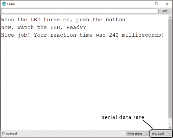
Notice that the bottom-right corner of the Serial Monitor has a pull-down menu to control the serial data rate in baud (bits per second), which defaults to 9,600 baud (see Figure 4-12). This is the same value this sketch uses to initialize the Serial object, using the Serial.begin(9600) instruction. Always check that the Serial Monitor speed is the same as the rate set in the sketch with Serial.begin()—otherwise, you may just get gibberish!
FIGURE 4-12: The Arduino IDE’s Serial Monitor window testing the Reaction Timer
NOTE
Some components, such as GPS or a serial-enabled LCD screen, will communicate with the Arduino at different baud rates, so when using a new part, it’s a good idea to check what rate it uses and set that in the sketch.
You can set the serial data rate to any standard rate from 300 to 250,000 baud, but 9,600 baud is the most common speed. Generally speaking, slower speeds are more reliable and use less power and fewer resources on the Arduino, but they also introduce a delay that slows down the loop(). If you need a really fast response and don’t care much about power usage, you can use a faster baud rate.
Now, let’s play! Run the sketch and watch your LED closely. When it lights up, push the button. Your code will print your reaction time, in milliseconds, to the Serial Monitor, like in Figure 4-12. How fast are you? Go challenge one of your friends! The average is about 215 ms. How do you measure up?
TRY IT OUT: MAKE WAITTIME MORE RANDOM
In most digital devices like an Arduino, it’s hard to get a truly random number because the random number is generated through a mathematical calculation. On an Arduino, each time the random() function is called, the function bases its calculation on the previous result from random(). Because the next “random” number is calculated from the previous result, the sequence of numbers will always be the same.
For example, on our Arduino (and probably yours), the first call to random(2000, 4000) will always set waitTime to 2807. The second number generated will always be 3249, the third will be 2073, and so on.
You can make the waitTime value appear more random by calling the function randomSeed() in your setup() function. This generates a seed value that tells random() where the pseudorandom sequence should start. When your Arduino starts running a sketch, the seed defaults to 1, which is why 2807 is always the first number generated by the random(2000, 4000) call.
To make your Reaction Timer behave more randomly, add this line of code to your setup() routine, just before the closing curly bracket:
randomSeed(analogRead(A5));
This seeds the random-number generator with the current voltage value on the Arduino’s analog pin A5. We’ll cover analogRead() in more detail in Chapter 5, but for now, just know that it reads the voltage level on the analog pin passed to it. Because pin A5 isn’t connected to anything in the Reaction Timer, the voltage floats, or bounces around somewhat unpredictably.
If you choose to add this line of code, then each time you run your sketch, the first call to random(2000, 4000) should return a different number. To confirm, add these two lines of code after the delay(waitTime) call in your sketch:
Serial.print("waitTime = ");
Serial.println(waitTime);
Now, comment out the randomSeed() call by adding // at the beginning of the line, run your sketch a few times, and note the initial waitTime values printed. Uncomment the randomSeed() call and repeat the process. Over time and a lot of data points, there will still be a pattern, but that’s a topic for another book—or perhaps for a degree in computer science!
Play Again?
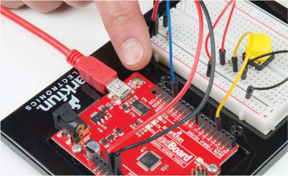
To play again, simply press the Arduino’s reset button—the brass-colored button near the corner of the board, shown in Figure 4-13. This will restart your code and let you play again. Watch the LED closely. Are you any faster?
FIGURE 4-13: Press the reset button to play again.
Add a Game Element
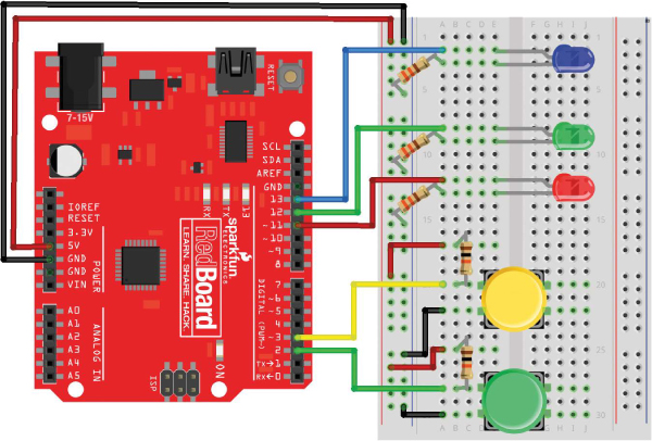
To add a little carnival-game style to this project, you can add a visual speed indicator to show if you’re faster than a given reaction time. We suggest starting with the average, 215 ms, as the time to beat. To do this, you’ll need to add two more LEDs: a green one to indicate that you were faster than the time set in the code and a red one to say you were slower. Since you already used pin 13 for the stimulus LED, you’ll connect these two LEDs to pins 11 and 12. Add these to your breadboard as shown in Figures 4-14 and 4-15.
FIGURE 4-14: Circuit diagram with two extra LEDs
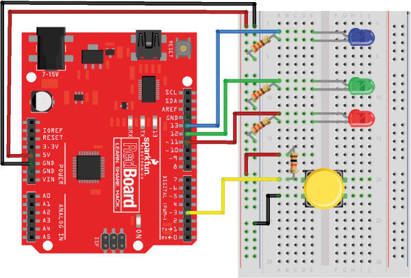
FIGURE 4-15: Completed wiring of the new circuit with two extra LEDs
Update the Code for Extra LEDs
Now that you have these two indicator LEDs, you’ll add a few extra lines of code to your project to turn on the green LED if you’re faster than the time to beat and the red LED if you’re not.
You’ll need to add a pinMode() command for pins 12 and 11 and set these up as OUTPUTs to control your new LEDs. The changes to the setup() function are shown in Listing 4-3 (the existing code is shown in light gray).
LISTING 4-3: The modified setup() function for the Reaction Timer with the extra speed-indicator LEDs
void setup()
{
Serial.begin(9600); //sets up serial
//communication
pinMode(13, OUTPUT); //sets pin 13 as an OUTPUT for the
//stimulus LED
pinMode(12, OUTPUT); //sets pin 12 as an OUTPUT for the
//green LED
pinMode(11, OUTPUT); //sets pin 11 as an OUTPUT for the
//red LED
pinMode(3, INPUT); //sets pin 3 as an INPUT for the
//button
}
You simply inserted two extra pinMode() instructions for the two extra LEDs that you’re going to add.
Control the Flow with if() and else()
Now you’ll need to add a little bit of decision logic into your sketch. In Arduino programming, an if() statement allows you to control the direction and flow of a sketch. It tells the code “if this is true, run the code in the following curly brackets.” The general syntax for the if() statement is shown in Listing 4-4.
LISTING 4-4: Generic if() statement in Arduino
if(➊expression) //if expression is true, run the code in
//the following loop
{
➋
}
➌ else //otherwise, run the code in this loop instead
{
➍
}
The expression ➊ is a Boolean expression that is either true or false, like the ones we discussed earlier in “Logical Comparison Operators” on page 106. If the expression is true, the sketch will start executing any code between the curly brackets ➋. If it’s not true, the sketch skips over the curly brackets and goes to the next statement. Oftentimes, the if() statement is paired with an else ➌. If the expression is not true, the sketch skips over the first set of curly brackets ➋ and continues on to the code that is part of the else statement ➍.
For the Reaction Timer game, you’ll use an if() statement to turn on the green LED if the reaction time is less than or equal to 215 ms and the red LED if the reaction time is greater than 215 ms. You’ll be able to change this value to make it harder or easier, but this is a good middling value for now. Listing 4-5 shows the code to do this.
LISTING 4-5: Code snippet of the if() statement for the Reaction Timer game
➊ if (➋reactTime <= 215)
{
➌ digitalWrite(12, HIGH); //green LED ON
➍ digitalWrite(11, LOW); //red LED OFF
}
➎ else
{
digitalWrite(12, LOW); //green LED OFF
digitalWrite(11, HIGH); //red LED ON
}
You can see at ➊ that the sketch uses the if() statement to perform this logic. The Boolean expression, reactTime <= 215 ➋, checks whether the value from reactTime is less than or equal to 215, and if it is, the green LED turns on ➌. When the green LED turns on, the red LED needs to be off, so you add one extra instruction ➍ to do that. Finally, you add the else statement ➎ to turn the red LED on if the if() statement evaluates to false.
Upload the Complete Code for the Reaction Timer
The new if() statement should be placed within the loop(), after the code to turn off the red LED, as shown in Listing 4-6. (The snip indicates where existing code has been omitted on the page for length.)
LISTING 4-6: Adding the if() statement for the green and red LED game indicators
--snip--
//loop to wait until button is pressed
while(digitalRead(3) == HIGH)
{
}
reactTime = millis() - startTime; //calculation of reaction
//time
digitalWrite(13, LOW); //turn off LED!
if (reactTime <= 215)
{
digitalWrite(12, HIGH); //green LED ON
digitalWrite(11, LOW); //red LED OFF
}
else
{
digitalWrite(12, LOW); //green LED OFF
digitalWrite(11, HIGH); //red LED ON
}
//display information to Serial Monitor
--snip--
After you’ve added the new code, upload the whole sketch to your Arduino. Open the Serial Monitor and play a game to make sure it all works as expected. Can you get the green light to turn on? You have to be fast!
GAMING THE GAME: CONTROL THE DIFFICULTY
As with all games, with the Reaction Timer, sometimes you’ll need to adjust the difficulty level. Since you’re the programmer, you get to control the game. If 215 ms is too fast or too slow, you can adjust your game threshold by changing the number in the line if (reactTime <= 215).
Want to make it impossible to beat? Change this value to a low number like 100 ms. Want to be nice and make it easier? Change it to a number like 500 ms. You’re writing the code, so you get to decide the rules of the game!
BUILD THE REACTION TIMER ENCLOSURE
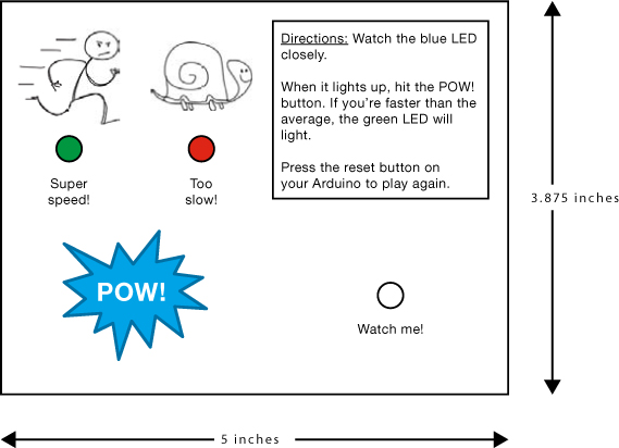
When your prototype works, it’s time to build a more permanent enclosure. To keep this project as simple as possible, our version of the Reaction Timer is designed to fit into a small SparkFun box. The top of the box measures 3 7/8 inches × 5 inches, but you can put your game in anything you have lying around the house—an old cereal box, oatmeal container, or anything else made of a sturdy cardboard.
We made our Reaction Timer look like an old-school carnival game with a few fun clip-art drawings we found, but you can make yours look however you want. Figure 4-16 shows a template for the outside of our box. For this design, we have a hole for the button, a hole for the stimulus LED, and two holes for indicator LEDs—one to show that you’re faster than a ninja and the other to show that you’re as slow as a turtle. You can download the template with this book’s resources via https://www.nostarch.com/arduinoinventor/ or just cut holes for the LEDs and buttons anywhere you like on your box.
FIGURE 4-16: Template for the Reaction Timer carnival game cover art (not full size)
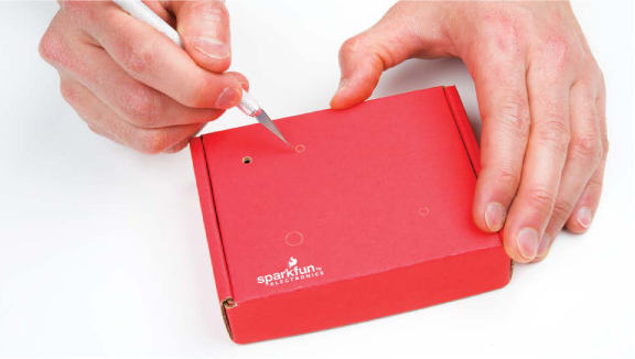
Cut Out the Cardboard
If you use our template, print it and then glue or tape it to the front of your box. Whether you use the template or not, you’ll need to make a total of four holes in the cardboard for the three LEDs and the button. You can use a craft knife or a drill to carefully cut out the holes, as shown in Figure 4-17. The LEDs are 5 mm in diameter, so a 3/16-inch drill bit is a pretty close fit. For the button hole, we recommend using a 5/16-inch drill bit, if you’re drilling, or a sharp pencil.
FIGURE 4-17: Cutting out the holes from a cardboard box
Assemble the Electronics
Now that you have the holes cut out of your Reaction Timer box, you need to add the electronic components. You’re going to move the three LEDs and the button from the breadboard to the exterior of your new cardboard box so that players can see them.
Attach the LEDs and Button to the Cardboard
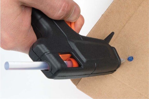
First, press the LEDs through their three holes from the back side of the cardboard, making sure that each sits snugly. If the holes you cut are too big and the LEDs are a little loose, simply add a small dab of glue to keep them in, as in Figure 4-18.
FIGURE 4-18: Moving the LEDs to your project box/ cardboard
Next, add the button. The push buttons that come in the SparkFun Inventor’s Kit have a cap that pops off. Remove the button cap, insert the button from the inside of the box, and glue the button onto the cardboard, as in Figure 4-19. Reattach the button cap on the top side of the cardboard. Players are going to mash this button as they try to get the best score possible, so use a lot of glue to make sure it’s secure! When the glue is dry, try the button out. You need to be able to press the button in all the way, so make sure the cap doesn’t get caught on any cardboard when you press it down.
FIGURE 4-19: Secure the button in place with a lot of glue.
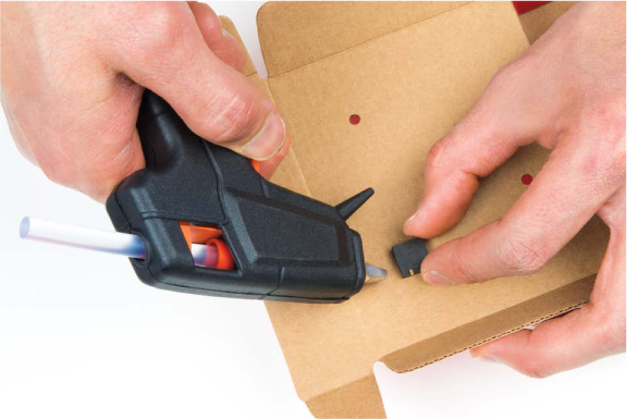
NOTE
If using hot glue, be cautious when gluing the button to the cardboard. Hot glue is hot!
Reconnect the Components to the Arduino
Now, use male-to-female jumper wires to connect the LEDs to the breadboard. Remember that the shorter leg of the LED needs to connect to ground (GND) in the circuit, and each of the longer legs should connect to its respective pin on the Arduino, through a 330 Ω resistor. Because the LED legs are a bit long, you may need to clip them back with wire cutters. A strategy we often use is to cut the shorter leg just a little shorter so that you can always tell which leg is the negative leg, as shown in Figure 4-20.
FIGURE 4-20: Cutting back the LED legs. Keep the short leg short!
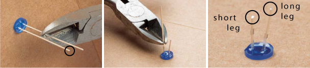
If you can’t tell which leg is longer, you can also look at the shape of the plastic lens on the LED. There is typically a flat edge on the side nearest to the negative leg of the LED. The flat edge is subtle, but if you look closely, you should be able to see it.
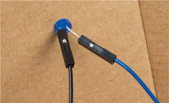
Press the female ends of the male-to-female jumper wires onto the ends of the LEDs so that they fit snugly, like in Figure 4-21. To keep things organized and easy to follow, we recommend using a black wire for the negative (short leg) of the LED.
FIGURE 4-21: Connecting the LED to the jumper wires
Once the jumper wires are connected to all three LEDs, connect the male ends to the breadboard circuit. The wires for the stimulus LED should go to E2 and E3, for the green LED to E8 and E9, and for the red LED to E12 and E13.
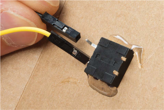
Next, reconnect the button to the circuit. The button has four legs, but you only need to connect to two legs on one side of the button. Connect one male-to-female wire to one leg and another to the other leg, as in Figure 4-22. Then, plug one wire into the same breadboard row that connects the 10 kΩ resistor and Arduino pin 3, and plug the other into GND on the breadboard. (If you wired up your breadboard prototype just like the diagram in Figure 4-14, then connect these wires to E20 and E22 on the breadboard.) Because the button is just a switch, it doesn’t matter which wire you plug into GND.
FIGURE 4-22: Connecting the male-to-female jumper wires to two legs on one side of the button
With your components in place, plug your Arduino into the computer and open the Serial Monitor to make sure your circuit still works. You should see your instruction messages on the Serial Monitor. When the blue LED lights, press the button as fast as you can. The Serial Monitor should show your reaction time, and either the red or green LED should turn on, based on how fast you were.
If your circuit doesn’t seem to be working, check that all of your connections are secure, and compare your circuit to Figures 4-14 and 4-15 to make sure the connections are correct.
Spice Up Your Game Enclosure
To finish up, add some bling to your new game. Use your imagination! You might want to cover your Reaction Timer with your favorite stickers or paint the box. We love using ping-pong balls in our projects, and since we had a half left over from Project 2, we decided to glue it on top of the blue LED, as in Figure 4-23.
FIGURE 4-23: Carnival-themed Reaction Timer game

GOING FURTHER
Next, try combining what you learned in the first three projects with what you know from this project to make it more interesting—add even more LEDs, or maybe make the game suitable for two players.
Hack
Add two more LEDs to make a four-LED scale that will show your speed more accurately. Faster reaction times will light up more LEDs. To do this, you’ll need the help of a nested if()–else if() control statement. You can stack your condition statements to tell the code what to do in different conditions, so if the first logical expression is false, the next one is tested; if that’s also false, the next is tested; and so on until the final else() statement, which runs if none of the previous conditions were true. Listing 4-7 shows an example of this conditional logic. It assumes you’ve added two extra LEDs connected to pins 10 and 9. Don’t forget the pinMode() commands you’ll have to add to the setup()!
LISTING 4-7: Snippet of nested if()–else if() statement
➊ if (reactTime <= 215)
{
//turn all LEDs on
digitalWrite(12, HIGH);
digitalWrite(11, HIGH);
digitalWrite(10, HIGH);
digitalWrite(9, HIGH);
}
➋ else if (reactTime <= 250)
{
//turn three LEDs on
digitalWrite(12, LOW);
digitalWrite(11, HIGH);
digitalWrite(10, HIGH);
digitalWrite(9, HIGH);
}
➌ else if (reactTime <= 300)
{
//turn two LEDs on
digitalWrite(12, LOW);
digitalWrite(11, LOW);
digitalWrite(10, HIGH);
digitalWrite(9, HIGH);
}
➍ else
{
//turn one LED on
digitalWrite(12, LOW);
digitalWrite(11, LOW);
digitalWrite(10, LOW);
digitalWrite(9, HIGH);
}
The if() statement at ➊ checks whether the reaction time is less than or equal to 215 ms and lights up all four LEDs. Then two else if() statements catch times between 215 ms and 250 ms ➋, lighting up three LEDs, and between 250 ms and 300 ms ➌, lighting up two LEDs. Finally, an else statement ➍ catches all times slower than 300 ms and lights up a single LED.
If you need a little more help with the code, check out our example sketch in the resources at https://www.nostarch.com/arduinoinventor/.
Modify
One fun way to modify this project would be to make it a two-player game. You could add a second button and repurpose your LEDs to indicate which player is faster. In this modification, the green LED will light up if Player 1 is faster, and the red LED will light up if Player 2 is faster.
First, add a second button. Figure 4-24 shows the additional button at the bottom of the breadboard. Notice that it’s just a duplication of the pull-up resistor/button combination circuit that you built for the first button.
FIGURE 4-24: Adding a second button for two-player mode
NOTE
If both players hit the buttons at exactly the same time, the game will favor Player 1 (the green LED). Although this would be a really rare occurrence, how would you modify the code to light up both LEDs if both buttons are pressed at the same time?
The complete code for the two-player modification is available, along with the wiring diagram for the modification, at https://www.nostarch.com/arduinoinventor/.
Now, go and take your new game out on the town. Are you faster than your family? Are you faster than your friends? Who is the fastest person you know?
All materials on the site are licensed Creative Commons Attribution-Sharealike 3.0 Unported CC BY-SA 3.0 & GNU Free Documentation License (GFDL)
If you are the copyright holder of any material contained on our site and intend to remove it, please contact our site administrator for approval.
© 2016-2026 All site design rights belong to S.Y.A.