The Arduino Inventor's Guide (2017)
5 A Color-Mixing Night-Light
The wonderful thing about digital electronics and microcontrollers is that they are smart. They can read sensors and make decisions based on what those sensors tell them. Sensors are components that collect information about the environment around them and convert that into something a microcontroller can understand.
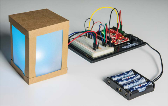
You can use sensors to make projects that react to all sorts of stimuli (like temperature, sound, and the proximity of an object), but in this project, we’ll start small with a night-light that reacts to changes in light level, shown in Figure 5-1.
FIGURE 5-1: Finished Night-Light project
MATERIALS TO GATHER
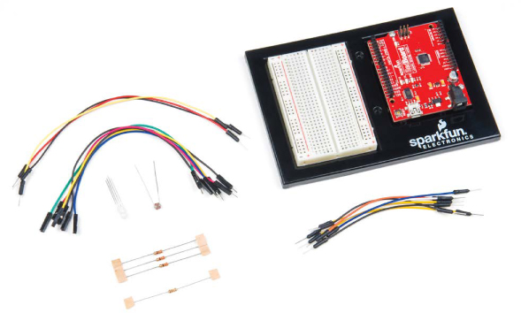
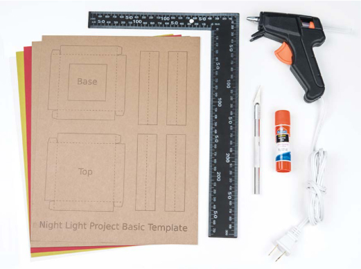
This project uses a new kind of LED and a photoresistor, a sensor that changes resistance based on how much light it detects. We encourage you to be creative and design a custom shade, too, but if you don’t feel up to that challenge yet, fear not! This book’s resource files include a shade design you can start with. Figures 5-2 and 5-3 show the parts and equipment you’ll need for this project.
Electronic Parts
NOTE
The parts marked with an asterisk (*) do not come with the standard SparkFun Inventor’s Kit but are available in the separate add-on kit.
• One SparkFun RedBoard (DEV-13975), Arduino Uno (DEV-11021), or another Arduino-compatible board
• One USB Mini-B cable (CAB-11301 or your board’s USB cable; not shown)
• One solderless breadboard (PRT-12002)
• One mini breadboard (PRT-12043*; not shown)
• One RGB LED, common cathode (COM-09264)
• Three 330 Ω resistors (COM-08377, or COM-11507 for a pack of 20)
• One 10 kΩ resistor (COM-08374, or COM-11508 for a pack of 20)
• One photoresistor (SEN-09088)
• Male-to-male jumper wires (PRT-11026)
• Short 4-inch male-to-male jumper wires (PRT-13870*)
• (Optional) Male-to-female jumper wires (PRT-09140*)
• (Optional) One 4 AA battery holder (PRT-09835*; not shown)
FIGURE 5-2: Components for the Night-Light
Other Materials and Tools
• Craft knife
• Metal ruler
• Glue (hot glue gun or craft glue)
• One sheet of cardstock (not cardboard), about 8.5 × 11 inches
• One sheet of white or translucent vellum, or standard copy paper, about 8.5 × 11 inches
• Enclosure template (see Figure 5-20 on page 144)
FIGURE 5-3: Recommended building materials for the Night-Light
NEW COMPONENTS
You’ll be using two new components in this project: an LED that has three colors integrated into a single package, and a photoresistor. Let’s take a look at how these components work.
The RGB LED
If you’ve built any of the other projects in this book, then you already have experience with regular LEDs. The red, green, blue (RGB) LED shown in Figure 5-4 works very similarly. This LED is actually three LEDs in one package: one red, one green, and one blue. Each LED has its own positive (or anode) leg, but they all share a single negative (or cathode) leg, called the common cathode.
If you look closely at the LED in Figure 5-4, you’ll notice that the legs are all different lengths. With regular LEDs, the short leg is the negative leg, but with the RGB LED, the longest leg is the negative leg. The circuit diagram for this component is usually drawn like Figure 5-5. Notice that it shows three separate LEDs connected together, and they each share a single negative connection.
FIGURE 5-4: An RGB LED with a common cathode leg
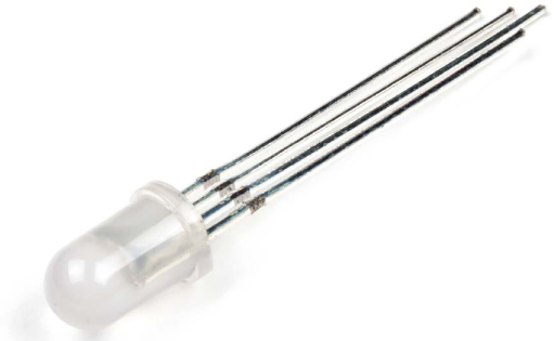
FIGURE 5-5: Circuit diagram of an RGB LED
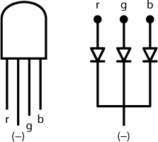
To figure out which positive leg is which color for this particular LED, orient the LED so that it looks like the one shown in Figure 5-5. In this orientation, the leftmost leg is the red positive leg. The next leg (the longest one) is the shared negative leg, and the last two legs are the green and blue positive legs, respectively.
Keeping in mind which positive leg corresponds to which color, you can wire this LED into a circuit just like you would three separate LEDs. Just connect the positive leg(s) you want to use to power or to an Arduino output pin through a current-limiting resistor, and connect the common cathode to ground.
RGB LEDs are cool because you can use them to create a slew of colors. Red, green, and blue are the primary colors in the additive color scheme, and the LED can mix these colors to create light in other colors. (This is different from the primary pigments—red, blue, and yellow—which, as you might remember from grade-school art class, mix together in paints to create new colors.) The additive color wheel in Figure 5-6 shows how primary colors can combine to create any color in the rainbow.
FIGURE 5-6: The additive color wheel
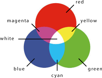
With your RGB LED, if you turn on the blue LED and the red LED together, you get magenta light. Combine the red and green LEDs, and you get yellow. If all the LEDs are on, you get white light. This concept is the foundation for how an LED TV or monitor works: each pixel on your screen is essentially an RGB LED.
The Photoresistor
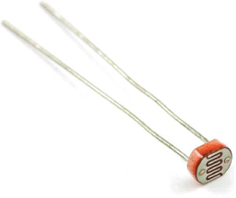
This Night-Light will turn on when it is in a dark room and turn off when the room is bright. That means the Night-Light needs to determine whether the room is dark. To do so, it uses a light sensor to monitor the light level of its surroundings. There are a number of different light sensors available, but we used the simple photoresistor shown in Figure 5-7. This component is sometimes also called a light-dependent resistor (LDR) or a photocell. Also, similar to many other types of sensors, a photoresistor is sometimes referred to as a variable resistor sensor.
The resistance of the photoresistor in this project varies from about 80 Ω to around 1,000,000 Ω (1 MΩ) depending on how much light it is exposed to. The photoresistor has a low resistance when exposed to bright light and a high resistance when it’s in the dark.
FIGURE 5-7: A photoresistor
To use the photoresistor to measure brightness, you have to place it in a voltage divider circuit, like the one in Figure 5-8. A voltage divider uses two resistors wired in series (that is, in line with each other) between a supply voltage (5 V) and ground to obtain a smaller voltage.
FIGURE 5-8: Voltage divider circuit
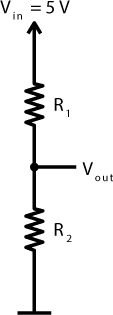
The total voltage across these two resistors is 5 V, and the voltages across R1 and R2 depend on the ratio of the two resistors’ resistances. Vout will be some voltage between 5 V and 0 V, because the voltage is divided between the two resistors. The relationship between Vout and the resistor values R1 and R2 can be characterized by the following equation.
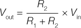
We know what you’re thinking: that looks like math! Well, it is, and math is an important part of electronics, but it doesn’t have to be complicated. We’ll take things slow to make sure everyone understands it as we go along. This little equation is especially helpful when you’re dealing with this photoresistor or any other type of resistive sensor. In the voltage divider circuit, if you replace R1 with the photoresistor, you get the circuit shown in Figure 5-9.
FIGURE 5-9: A voltage divider circuit with a photoresistor
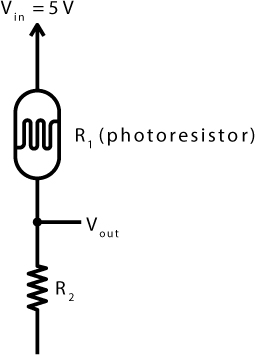
The resistance of the photoresistor increases as the light around it gets dim. Now, look at the voltage divider equation. As resistance R1 increases, the denominator of the fraction increases, making the entire fraction smaller. That means Vout gets smaller as it gets darker.
With this circuit, you can accurately read the amount of light on the photoresistor by connecting Vout to an analog input pin on the left-hand side of the Arduino (the pins marked with an A). Analog signals are those that can vary across a range of values. Up to this point, you’ve only used the digital pins on the right-hand side of the Arduino board. Unlike a push button, which has only two states, the photoresistor can have a range of values based on the brightness of light and the voltage divider circuit. This is the difference between a digital and an analog signal.
That’s all you really need to know to use this voltage divider circuit, but if you want to practice the calculations, see “Show Me Some Math: Voltage Dividers” on page 130.
SHOW ME SOME MATH: VOLTAGE DIVIDERS
Using a multimeter, you can measure the resistance of a photoresistor under different conditions. (For instructions on using a multimeter, see “Measuring Electricity with a Multimeter” on page 298.) When we shined a bright light from a flashlight or cell phone on the photoresistor, we measured a resistance of about 100 Ω. When we covered the photoresistor with our hands, we saw a resistance of about 200 kΩ. With the fixed resistor (R2) set at 10 kΩ, we’d expect to see the following values from the voltage divider in those two situations:
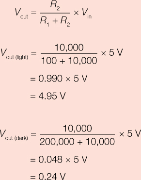
With an input voltage of 5 V, the voltage across the photoresistor varies from 0.24 V to 4.95 V through a range of light levels. We’ll show you how to use the Arduino to read these voltages in this chapter. Pretty cool, right? Math works!
BUILD THE NIGHT-LIGHT PROTOTYPE
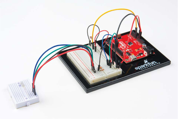
Let’s put the RGB LED and the voltage divider together to build the Night-Light circuit. You’ll start by building the voltage divider circuit with the photoresistor and then add the RGB LED. When you’re done, your breadboard should look like Figure 5-10. We’ve also included a circuit diagram in Figure 5-11 for your reference.
FIGURE 5-10: Completed prototype circuit
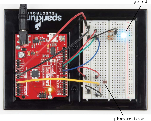
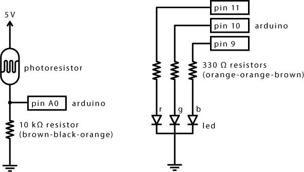
FIGURE 5-11: Circuit diagram of completed prototype Night-Light circuit
Wire the Voltage Divider
Find your photoresistor (it should look like the one in Figure 5-7) and a 10 kΩ resistor. Recall that a 10 kΩ resistor has brown, black, and orange color bands, as shown in Figure 5-12. See “Resistors and Bands” on page 308 for details on how to determine the value of a resistor from its color bands.
FIGURE 5-12: 10 kΩ resistor (brown-black-orange)
![]()
With your parts in hand, build the voltage divider circuit as shown in Figure 5-13. It’s good practice to connect both power (5 V) and ground when setting up the breadboard for building circuits, so do that first. Find the ground rail (–) and the power rail (+) on the left side of your breadboard. Connect 5 V on the Arduino to the power rail, and connect GND on the Arduino to the ground rail.
FIGURE 5-13: Completed voltage divider, using the photoresistor
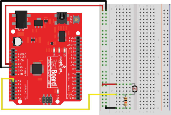
Next, plug the photoresistor in near the bottom of the breadboard, with each leg in its own row. Plug one side of the 10 kΩ resistor into the same row as one of the photoresistor legs (connecting the two together), and plug the other side of the resistor into a row by itself. Add a wire to connect the 5 V power rail (+) to the photoresistor leg that isn’t connected to the resistor. Then, add another wire to connect the ground rail (–) to the resistor leg that’s in a row by itself.
Finally, connect the photoresistor to the Arduino by running a wire from the breadboard row that’s shared with both a leg from the resistor and a leg from the photoresistor to the Arduino analog input pin A0. This wire is often called the output voltage of the photoresistor, or the signal wire. The analog input pins, A0–A5, can all be used to measure a range of voltages.
Notice how the breadboard circuit looks a lot like the diagram in Figure 5-9. This is one of the most basic sensor circuits used in Arduino projects. Many other analog sensors, like sensors for flex, temperature, and pressure, are variable resistors, too. To experiment with one of those later, just replace the photoresistor with that sensor.
Wire the RGB LED
Remember the Stoplight circuit in Project 2? That project had three LEDs. The RGB LED basically squishes those three LEDs together. The RGB LED has four legs, and the longest leg is the common cathode (negative) leg. With your RGB LED oriented as in Figure 5-5, find the red leg. Plug the RGB LED into the breadboard so that the red leg is at the top and the longest leg is the second one down, as shown in Figure 5-14.
FIGURE 5-14: Adding the RGB LED to the voltage divider circuit
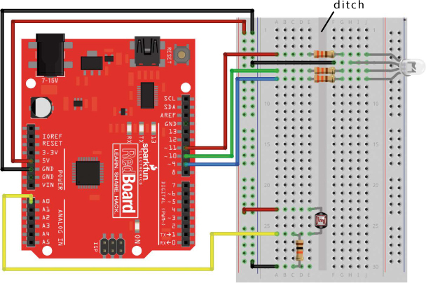
The two halves of the breadboard are divided by a ditch that separates the rows. Plug the RGB LED into the right side, starting with the red pin in row 4.
Next, find three 330 Ω resistors; their color bands are orange-orange-brown. Use the three resistors to bridge the red, green, and blue pins across the ditch to open rows on the other side, as shown in Figure 5-14. The resistors need to straddle the ditch so that the two ends of the resistors aren’t shorted together. Run a wire from the common cathode (negative) leg of the LED to the ground rail on the left side of the breadboard. Finally, connect the three pins of the RGB LED to the Arduino by running a wire from pin 11 on the Arduino to the resistor connected to the red pin on the breadboard, pin 10 on the Arduino to the resistor for the green pin on the breadboard, and pin 9 on the Arduino to the resistor for the blue pin on the breadboard. When you’re done, it should resemble the diagram in Figure 5-14. Notice that the red, green, and blue wires correspond to the red, green, and blue positive legs on the LED.
With the RGB LED hooked up, you can control each color like a separate LED, using pins 9, 10, and 11. Open up the Arduino IDE, and let’s play with this idea!
TEST THE NIGHT-LIGHT WITH BASIC COLOR MIXING
You’ll tackle a few new concepts with this project, starting with how to mix colors using an RGB LED. The RGB LED is really three LEDs in one, and you need to treat it that way in your code. Create a new sketch, and replace the default code with the setup() and loop() functions in Listing 5-1.
LISTING 5-1: A simple code example to display cyan on the RGB LED
void setup()
{
➊ pinMode(11, OUTPUT); //red
pinMode(10, OUTPUT); //green
pinMode(9, OUTPUT); //blue
}
void loop()
{
➋ digitalWrite(11, LOW); //red
➌ digitalWrite(10, HIGH); //green
➍ digitalWrite(9, HIGH); //blue
}
Each pin that controls the RGB LED needs its own pinMode() function to set that pin as an OUTPUT ➊. Previous projects used the digitalWrite() function to turn LEDs on and off with individual pins, and you’re going to do the same with the RGB LED. Using the color wheel in Figure 5-6, choose from any of the colors represented. We selected cyan, the combination of green and blue. To create cyan, you need to turn on the green ➌ and blue ➍ LEDs using the digitalWrite() function. To make sure that the red LED is off, the code also needs a third digitalWrite() function ➋.
Upload this sketch to your Arduino, and if the circuit is wired up correctly and the code is correct, your RGB LED should glow with a soft cyan light. If it’s a different color or not lighting up at all, check your wiring and the orientation of the RGB LED.
Notice that even though you’re using the RGB LED to mix colors, your code is still pretty similar to the code from other LED projects in this book. Each LED is turned on by a separate digital pin using the pinMode() function. You’re just controlling the colors by using multiple digitalWrite() functions at the same time.
TRY IT OUT: MIX MORE COLORS!
Try changing the color of the LED on your own, and this time, incorporate red into the color. Can you make magenta? What about yellow? What color do you get when you turn all three colors on? Use the color wheel as a reference.
PROGRAM THE NIGHT-LIGHT
In the Night-Light circuit, the photoresistor is used as a light sensor. The photoresistor voltage divider is connected to analog input pin A0. Recall that the Arduino can be used to measure voltage on any of the analog input pins. You can have the Arduino read the sensor value from that pin using the analogRead() function. The analogRead() function reads the voltage applied to an analog input pin and returns a value between 0 and 1,023, scaled from a voltage range of 0 V to 5 V. For example, if you applied 2.5 V to A0, the analogRead(A0) function would return a value of about 512, or roughly half of 1,023.
As the amount of light hitting the photoresistor changes, its resistance changes, and because of the voltage divider circuit, the voltage on the analog input pin changes, too. Let’s see how to code this on the Arduino. To determine whether the Night-Light should be on or off, you want to read the voltage from the photoresistor and compare it against a value that indicates whether the room is dark or bright. You should already have the circuit wired up, with the RGB LED and the photoresistor hooked up to pin A0. Listing 5-2 shows the Arduino sketch in its entirety. You can either modify the sketch you made for Listing 5-1 to match it or just add this code to a brand-new sketch.
LISTING 5-2: Complete Night-Light code
int calibrationValue;
int lightValue;
void setup()
{
pinMode(9, OUTPUT);
pinMode(10, OUTPUT);
pinMode(11, OUTPUT);
➊ calibrationValue = analogRead(A0);
}
void loop()
{
➋ lightValue = analogRead(A0);
if(lightValue < calibrationValue - 50)
{
digitalWrite(11, LOW); //red
digitalWrite(10, HIGH); //green
digitalWrite(9, HIGH); //blue
}
➌ else
{
digitalWrite(11, LOW); //red
digitalWrite(10, LOW); //green
digitalWrite(9, LOW); //blue
}
}
Upload this to your Arduino board, and make sure the room you’re in is brightly lit. When you shade the photoresistor enough with your hand, the RGB LED should turn on with a cyan color. If it doesn’t work, try cupping your hands around the photoresistor or covering it with a book or magazine to make sure that it doesn’t sense any light. Now, if you remove your hand and expose the photoresistor to light, the RGB LED should return to being off. Pretty cool! Let’s look at how this works.
Prepare to Check the Light Level
First, the sketch creates the calibrationValue and lightValue global variables without assigning values to them. Like the code in Listing 5-1, the setup() function calls pinMode() once for each pin of the RGB LED, setting pins 9, 10, and 11 to OUTPUT. Next, the sketch takes a single initial calibration reading from the photoresistor ➊ and places it in the calibrationValue variable. This is the value the sketch will compare future measured light levels against to decide whether to turn the LED on or not.
Now, jump into the loop() function. The loop() function repeatedly reads the current light level and stores it in the lightValue ➋ variable. The value of lightValue will be updated every time the loop() function repeats.
Control the Night-Light Based on the Light Level
With the initial light level stored in the calibrationValue variable and the current light level stored in the lightValue variable, the Arduino can compare the two and decide whether to turn the Night-Light on or off. You can tell the Arduino to do this by using an if() statement, a structure that controls the flow of code execution in a sketch. It allows the Arduino to make a decision based on the truth of an expression, a mathematical statement that has one of only two outcomes: true or false. You can see the basic flow of an if() statement in Figure 5-15.
FIGURE 5-15: The structural flow of an if() statement
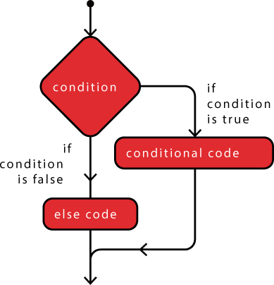
This sketch’s if() statement checks the expression lightValue < calibrationValue - 50. The < symbol means “less than,” so this statement reads, “Is lightValue less than calibrationValue minus 50?” If that expression is true, the sketch enacts the code inside the set of curly brackets just underneath the if() statement.
As the room gets darker, the voltage coming from the sensor circuit decreases. This expression checks if lightValue is significantly smaller than calibrationValue, which is true if the room has gotten darker. If it has, the sketch sets pins 9 and 10 HIGH and sets pin 11 LOW to turn the Night-Light on with a cyan color.
When the if() statement is false, the Arduino skips to the code that follows. This sketch includes an else ➌ statement, which gets executed only after an if() statement’s expression evaluates to false. Inside the else statement, the sketch turns off all three pins.
Prevent False Alarms
If the sketch just needs to check whether the light level has changed, why subtract 50 from the calibrationValue variable in the expression? Checking lightValue against a number smaller than calibrationValue increases the tolerance on the sketch. If you were to use the lightValue < calibrationValue expression, your Night-Light would flicker on and off at the smallest changes in light (flip back to “Logical Comparison Operators” on page 106 for more on the <symbol). Subtracting 50 from the calibration value makes sure that the Night-Light turns on when the light level is more than 50 below the calibration (initial) measurement.
Recalibrate the Night-Light
One last piece of useful information before you prettify your Night-Light is how to reset the calibration value to recalibrate for different light levels. The value of calibrationValue is set in the setup() function, so it runs only once. When your Arduino is powered, there are two different ways to restart your sketch. First, you can turn the Arduino off and on again, but that’s kind of annoying and unsophisticated. The second way is a little more elegant. As with Project 4, you can simply press the reset button shown in Figure 5-16 to restart your sketch. It works the same way as the reset button on a computer or game console. Every time you press that button, the calibration value for the Night-Light is reset.
FIGURE 5-16: The reset button in all of its clicky glory
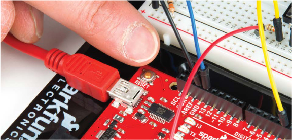
Each time you move your project into a new room or lighting situation, recalibrate your photoresistor by pressing the reset button. When you recalibrate your photoresistor, make sure that it’s reading the actual lighting conditions of your room and that you’re not accidentally shadowing it in any way.
CREATE MORE COLORS WITH ANALOGWRITE()
You’re not restricted to just the colors you’ve seen so far with the RGB LED. By mixing gradations of those colors, you can make cerulean, orange, powder pink, or any of the other thousands of combinations. But you can’t create these colors by just turning the different standard colors on an RGB LED on and off, so you need a way to turn red on just a bit and add a hint of blue and green to create, for example, pink.
Create Analog Signals with PWM
To use the LED in this way, you need to use analog values rather than digital values. In the Electronics Primer, we talked about the difference between analog and digital (page 10). A digital value can only be on or off, like a normal light switch. An analog signal has an infinite number of values, so it works on a scale, like a dimmer switch.
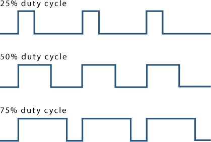
The problem is that the Arduino is a digital device, which means that it can only turn things on and off. To get it to output a value somewhere between on and off, you use a technique called pulse width modulation (PWM) to emulate an analog signal with digital values. The Arduino does this by turning a digital pin on and off extremely fast and then varying the relative amount of time the signal is HIGH (on) compared to the amount of time the signal is LOW(off) to create a signal that appears to be analog. The longer a pin is at a high value, the greater the analog value of the signal. This is sometimes also called varying the duty cycle. Figure 5-17 shows some duty cycles with varying pulse widths; the analog value of the pulse at 75 percent is higher than the value of the 25 percent duty cycle.
FIGURE 5-17: Duty cycle signals showing different widths of the pulse
That’s great, but not all Arduino pins have the ability to use PWM. On a standard Arduino, only certain GPIO pins—that is, pins 3, 5, 6, 9, 10, and 11—are PWM compatible. These pins are noted with a tilde (~) on the board, highlighted in Figure 5-18.
FIGURE 5-18: PWM pins on the standard RedBoard

Anytime you want to control something with varying values, like the brightness of an LED, the speed of a motor, or the tone of a buzzer, you’ll need to use a PWM pin to fake an analog signal. Here, we’ll use it to control the brightness of each color of the RGB LED in order to mix the colors. For this project, you have the RGB LED red, green, and blue pins already hooked up to PWM pins 11, 10, and 9, respectively, so you don’t have to change any of your wiring, only your code.
Mix Colors with analogWrite()
To utilize these PWM powers, you need to use the analogWrite() function, which writes a PWM value to a pin. The analogWrite() function accepts two parameters: the pin number that you want to control and a PWM value to write, which is always a range from 0 to 255. The value of 0 is completely off, and 255 is completely on. Let’s write a simple sketch that demonstrates the analogWrite() function.
void setup()
{
➊ pinMode(9, OUTPUT);
}
void loop()
{
➋ analogWrite(9, 2);
}
First, as with any other pin, you need to specify how you’re going to use the GPIO pin using the pinMode() function. You pass the pin number, and, since the LED is an output, you pass OUTPUT as you have in past projects ➊. To set a PWM value, you use the analogWrite() function to set an analog value between 0 and 255. In the example, pin 9 (the blue anode of the RGB LED) is set to an analog value of 2 ➋. Upload this sketch to your Arduino, and you should have a dim blue colored RGB LED. The analogWrite() value of 2 uses PWM to turn on this LED for about 0.7 percent or 2/255 of the time. Before moving on, try changing the PWM value and reuploading a few times to get a feel for the different values and their intensity.
Now that you have the hang of the analogWrite() function, try using it to mix colors. Listing 5-3 creates a blink pattern with different, more interesting colors than those used so far.
LISTING 5-3: Multicolored blink
void setup()
{
➊ pinMode(11, OUTPUT); //red
pinMode(10, OUTPUT); //green
pinMode(9, OUTPUT); //blue
}
void loop()
{
➋ analogWrite(11, 153); //dark orchid purple
analogWrite(10, 50);
analogWrite(9, 204);
delay(1000);
➌ analogWrite(11, 155); //pale cerulean
analogWrite(10, 196);
analogWrite(9, 226);
delay(1000);
➍ analogWrite(11, 255); //cadmium yellow
analogWrite(10, 246);
analogWrite(9, 0);
delay(1000);
}
First, add the other two color pins using the pinMode() function ➊. Then, cycle through three different colors by setting different analog values to the three pins. This sets the brightness level of each specific color, changing how much of that color is added to the final mix.
The first color set creates a bluish purple ➋, the second creates a dusty pale blue ➌, and the final set creates a bright yellow ➍. Play around with analogWrite() to create different colors.
Find RGB Values with Color Picker
You created some pretty specific colors before, but it can be hard to predict which RGB values will give you certain colors. An easy way of finding out is to use a color-picker tool on the web. There are plenty of them out there, but we recommend https://www.colorpicker.com/. This tool gives you the RGB values for colors you pick from a palette, as shown in Figure 5-19.
FIGURE 5-19: The color-selector tool from https://www.colorpicker.com/.
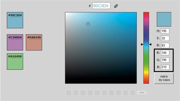
The three numbers you want to use are labeled R, G, B for the three colors Red, Green, and Blue. Ignore the top three H, S, B boxes; they refer to another common method for specifying colors called HSB (hue, saturation, and brightness). This is a useful technique for many color mixing and graphic design applications, but it’s not as useful when you have direct control over the three colors red, green, and blue.
The Custom-Color Night-Light Code
With the RGB knowledge in hand, now you can easily modify your Night-Light code to include your custom color by replacing your digitalWrite() function with analogWrite(). Listing 5-4 shows changes to the Night-Light code, with the color values set to the teal color we selected in Figure 5-19.
LISTING 5-4: Final Night-Light code with analogWrite() instead of digitalWrite() commands
int calibrationValue;
int lightValue;
void setup()
{
pinMode(9, OUTPUT);
pinMode(10, OUTPUT);
pinMode(11, OUTPUT);
calibrationValue = analogRead(A0);
}
void loop()
{
lightValue = analogRead(A0);
if(lightValue < calibrationValue - 50)
{
analogWrite(11, 66); //red
analogWrite(10, 166); //green
analogWrite(9, 199); //blue
}
else
{
analogWrite(11, 0); //red off
analogWrite(10, 0); //green off
analogWrite(9, 0); //blue off
}
}
With that, your Night-Light prototype is done! If you don’t like the teal we selected, use the color-selector tool to find a color you prefer, update your analogWrite() functions with its RGB value, and then re-upload your sketch before moving on. Visit http://99colors.net/color-names/ if you want to browse through some fun color suggestions.
Now that you have the code working, it’s time to get creative and build the enclosure and lampshade.
BUILD THE NIGHT-LIGHT ENCLOSURE
We suggest cardstock for this project’s enclosure rather than cardboard (as it produces cleaner edges and is easier to work with) and a vellum material or translucent paper for the shade. Let’s get building.
Cardstock Construction
We’ll show you a basic Night-Light design to get you started, but we encourage you to get creative by customizing the design later. Or, if you’re feeling confident, you can design your own Night-Light enclosure from scratch without using our templates at all.
Cut Out the Parts
This project has two templates: one for the structure of the Night-Light and one for the shade. The shade can be made from any material similar to printer paper in thickness, but we’ve found that a fully translucent material like vellum works best. If you have a printer, you can open the templates in Figure 5-20 from this book’s resource files and print them directly to your material to cut out.
FIGURE 5-20: Enclosure templates for the Night-Light (not full size)
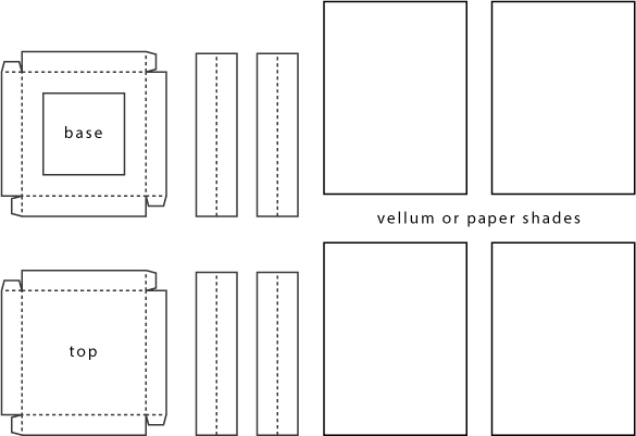
Note that the base of the Night-Light enclosure has a square cut out for access to wires. We also found it convenient to leave one of the four side panels off so that we could run the wires back to the larger breadboard more easily. We’ll leave it up to you whether to include that fourth panel.
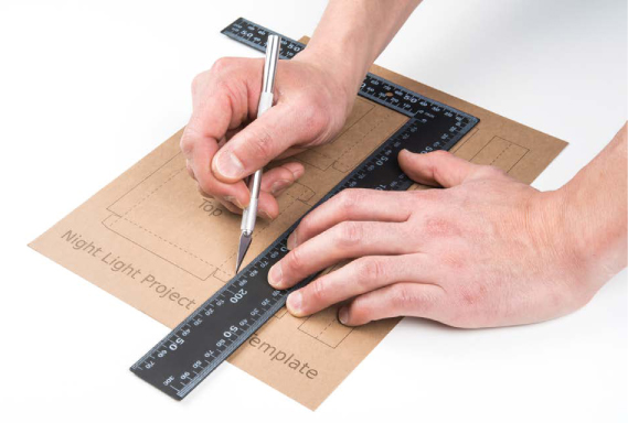
Once your template pieces are copied onto your cardstock and translucent material, cut them out. We highly recommend a sharp craft knife and a metal ruler to get clean edges for your project, as shown in Figure 5-21. Remember craft-knife safety: always pull the blade (don’t push), and make multiple passes.
FIGURE 5-21: Cutting out templates from cardstock
Assemble the Parts
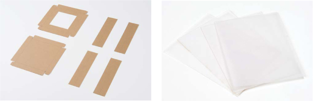
Arrange all of your pieces in front of you. You should have six pieces for the structure and four pieces for the shade material, as shown in Figure 5-22.
FIGURE 5-22: Individual parts cut out and ready for assembly
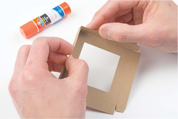
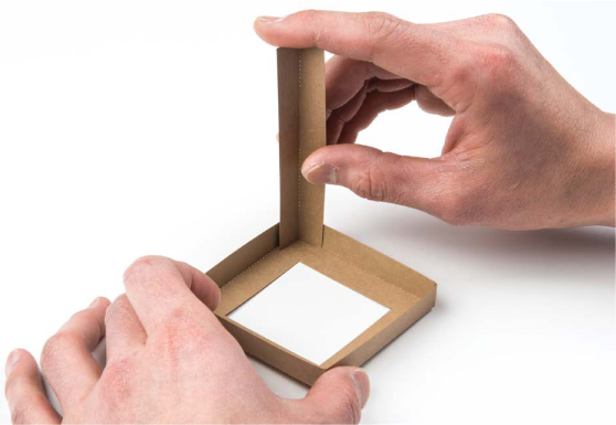
First, pick up the base (the piece with the center cut out). Hold it flat in front of you and fold the left and top edges toward you to form a right angle. Fold the tab on the left edge inward and secure it to the top edge with a small amount of glue, as shown in Figure 5-23. Repeat this for the other four corners of the base piece, and then use the same technique to assemble the top piece.
NOTE
Depending on your card-stock thickness, you may want to lightly score the fold lines with your craft knife. This will result in sharper, cleaner corners.
FIGURE 5-23: Assembling the base and top pieces
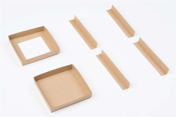
Next, fold each of the four side pieces down the middle lengthwise to form a nice 90-degree angle. There is a dotted line in the template to guide you. Once you have the top and base assembled and the sides folded, the six pieces should look like the ones in Figure 5-24.
FIGURE 5-24: Assembled pieces for the Night-Light enclosure
Finally, take each corner piece and glue it to the base, as shown in Figure 5-25.
FIGURE 5-25: Glue each corner piece to the base
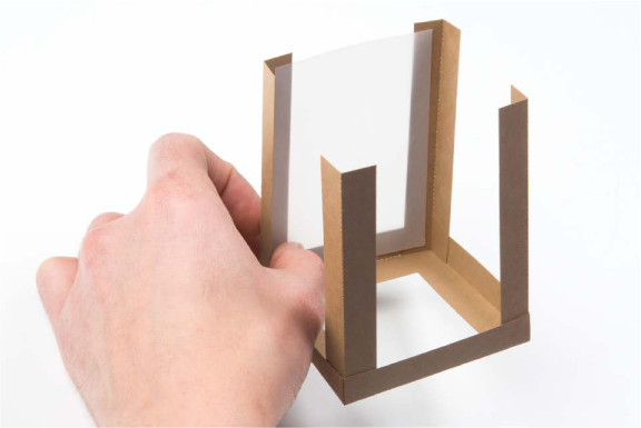
When you’re finished gluing corners, you should have four standing corner support structures. We found it easier to glue the shades in place before gluing the top piece, so just add a small dab of glue on the inside edge of each support structure, and press the shades into place, as shown in Figure 5-26. You may want to use only three shades, to allow access for wires.
FIGURE 5-26: Before adding the top piece, glue the shades into place.
When you’ve added all the panels you want, add the top piece. Simply add a small dab of glue on each corner to secure the top piece in place, as shown in Figure 5-27.
FIGURE 5-27: Adding the final top piece

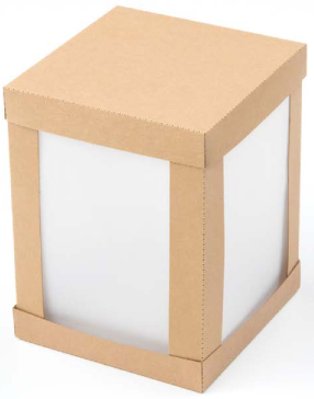
Now you should have a completed Night-Light enclosure like the one in Figure 5-28!
FIGURE 5-28: Final Night-Light enclosure
Put the Electronics Inside
You have a couple of options for transferring the electronics into your new project: put the breadboard and the Arduino baseplate under the Night-Light, or move just the LED inside the Night-Light. We took the second approach.
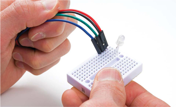
First, unplug your Arduino from the computer, and then move the RGB LED onto a mini breadboard. The mini breadboard works the same way as its bigger cousin does; it just lacks power rails and is shorter. Add jumper wires to the mini breadboard to make the connection from the LED back to your original circuit, as shown in Figure 5-29. Notice that each of the four legs of the RGB LED is in a separate row: one for the red leg, one for the ground leg (the longest), one for green, and one for blue.
FIGURE 5-29: Using the mini breadboard to move the RGB LED inside the Night-Light
Now, connect the other end of each jumper wire to the breadboard row where the corresponding RGB LED leg used to be, as in Figure 5-30.
FIGURE 5-30: Connecting the mini breadboard back to the main circuit
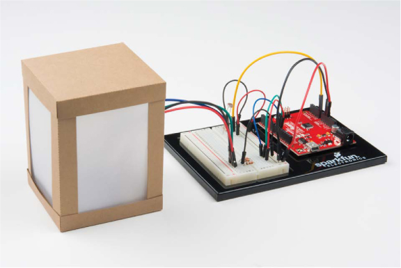
If you left one of the sides open, simply run the wires out the back of the lamp enclosure, like we did in Figure 5-31. Otherwise, carefully place your shade over the mini breadboard, and either tape your jumper wires to the table so the shade stays flat or make a couple of notches in the cardboard at the bottom of the enclosure for the wires to fit through.
FIGURE 5-31: Placing the shade on top of the mini breadboard
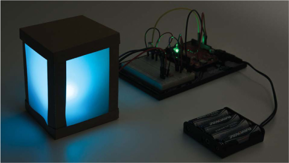
Let It Glow!
If you have the external battery pack, you can now put four AA batteries in, and plug the barrel jack into the Arduino. The board should still be programmed and running, so just turn off the lights. You should get a nice, softly glowing night-light, like ours in Figure 5-32.
FIGURE 5-32: Lights out! Our final glowing Night-Light project.
GOING FURTHER
This project used a lot of new skills and knowledge, but it still has a load of potential for further hacking. There are plenty of things you can do in terms of both the design and the code as you build your skills with Arduino.
Hack
One great sketch hack would be to have the colors change periodically when the Night-Light is on. For some hints, look back at your Stoplight project code. One method would be to add some simple blink code within the if()statement rather than just digitalWrite() functions and build a color animation.
You could also try adding different colors for different light readings using the else if() command rather than just if() or else on its own. The base structure of this method might look something like Listing 5-5.
LISTING 5-5: Three-stage Night-Light code example
if (lightValue < calibrationValue - 200)
{
//do if it is completely dark
digitalWrite(11, HIGH);
digitalWrite(10, LOW);
}
else if (lightValue < calibrationValue - 50)
{
//do if it is a little dim
digitalWrite(11, LOW);
digitalWrite(10, HIGH);
}
else
{
//do if it is bright
digitalWrite(11, LOW);
digitalWrite(10, LOW);
}
You can see the sketch uses else if() to set categories of light value. You would then need to set the color for each category.
Modify
The design of your Night-Light is totally up to you, so you can create a whole new design if you want. There are a number of tools you can use to design an enclosure and then produce it through automated means, such as laser cutting with balsa wood, 3D printing with materials like ABS or HIPS plastics, or even CNC milling, routing, or machining. Computer-controlled manufacturing will produce superclean and accurate parts that will amount to a more refined product. We encourage you to explore these possibilities to create something more permanent and polished. If you don’t have access to these kinds of tools, try looking into local hacker or maker spaces in your city. Often they’ll have facilities and tools that you can work with.
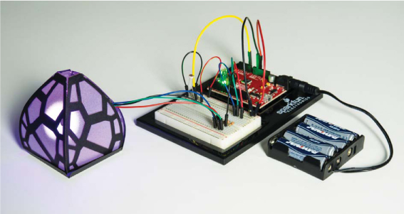
We have included a few example templates and ideas of projects that you can build and adapt at https://www.nostarch.com/arduinoinventor/. Figure 5-33 shows an example of how you can break up the lampshade design with some fun patterns.
FIGURE 5-33: A fun design from our design templates.
All materials on the site are licensed Creative Commons Attribution-Sharealike 3.0 Unported CC BY-SA 3.0 & GNU Free Documentation License (GFDL)
If you are the copyright holder of any material contained on our site and intend to remove it, please contact our site administrator for approval.
© 2016-2026 All site design rights belong to S.Y.A.