The Arduino Inventor's Guide (2017)
6 Balance Beam
In this project, you’ll build a desktop balance beam game using a turn knob and a servo motor (a small motor capable of making precise movements). The aim of the game is to roll a ball back and forth along the beam without it falling off. You’ll do this by using the turn knob to control the position of the servo. As the servo moves, so will the beam! Ready to get started?
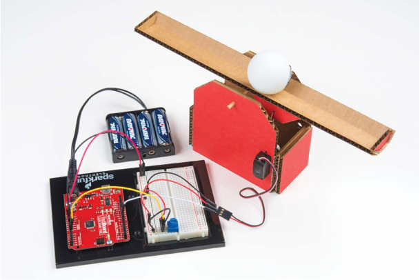
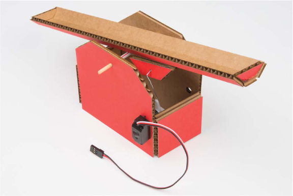
Figure 6-1 shows the finished project. This is a simple mechanism that is made entirely of cardboard and a few household materials.
FIGURE 6-1: The finished Balance Beam project
MATERIALS TO GATHER
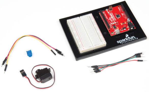
The circuit for this project uses relatively few parts, though we will introduce two new pieces of hardware: the servo motor and the potentiometer. Take a look at the electronic parts and other materials you’ll need, shown in Figures 6-2 through 6-4.
Electronic Parts
• One SparkFun RedBoard (DEV-13975), Arduino Uno (DEV-11021), or any other Arduino-compatible board
• One USB Mini-B cable (CAB-11301 or your board’s USB cable; not shown)
• One solderless breadboard (PRT-12002)
• One 10 kΩ potentiometer (COM-09806)
• One submicro size servo motor (ROB-09065)
• Male-to-male jumper wires (PRT-11026)
NOTE
All of the parts used in this project are standard in the SparkFun Inventor’s Kit.
FIGURE 6-2: Components for the Balance Beam
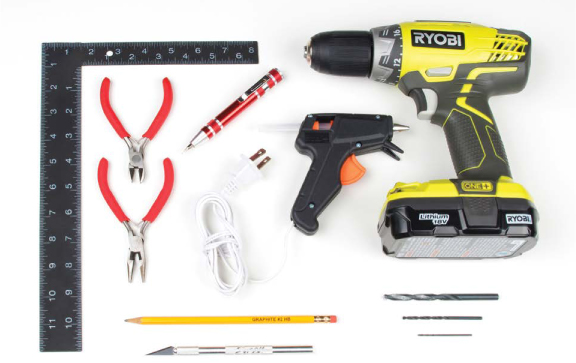
Other Materials and Tools
• Pencil or marker
• Craft knife
• Metal ruler
• Needle-nose pliers
• Wire cutters
• Glue (hot glue gun or craft glue)
• Mini screwdriver
• Scissors (not shown)
• (Optional) Drill and 1/4-inch, 1/8-inch, and 1/16-inch bits
• Two sheets of cardboard (roughly 8.5 × 11 inches in size)
• Balance Beam template (see Figure 6-16 on page 167)
• One bamboo skewer
• One small drinking straw (the bamboo skewer should fit into the straw loosely)
• One ping-pong ball
• One medium-size paper clip
FIGURE 6-3: Recommended building materials

FIGURE 6-4: Recommended tools
NEW COMPONENTS
In the previous projects, you’ve mostly used your Arduino to control LEDs, but now it’s time to branch out and explore other components. This project introduces a new sensor, called a potentiometer, and motors, specifically the servo motor.
The Potentiometer
In this project, you’ll use a potentiometer to control the movement of the Balance Beam. A potentiometer is a kind of sensor known as a variable resistor, which just means it’s a resistor whose value can vary.
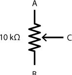
A potentiometer generally has three legs or connection points and is represented by the symbol shown in Figure 6-5.
FIGURE 6-5: Schematic diagram for a potentiometer
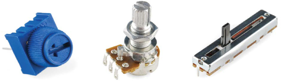
Potentiometers come in many shapes and sizes, a few of which are shown in Figure 6-6. Some look like turn knobs, some are sliders, and others require a small screwdriver to manipulate. Regardless of their appearance, they all work in the same way. And they are all around you—at home, you might find them in the dimmer switch of your dining room light, in the volume knob on your stereo, or inside devices like DVD players.
FIGURE 6-6: Various shapes and sizes of potentiometers. We’ll be using the one on the left.
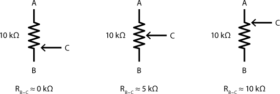
A potentiometer has a fixed resistance between the two opposite legs marked A and B in Figure 6-7. Potentiometers can come in all sorts of resistance values, but for this project you’ll use a 10 kΩ potentiometer. As you turn the knob or move the slider, the third leg of the potentiometer (marked C), called the wiper, moves up or down the resistor, and the resistance between B and C changes. It’s this resistance value that’s applied to the circuit.
If you turn the knob clockwise, the wiper moves toward A and the resistance between C and B increases; if you turn the knob counterclockwise, the wiper moves toward B and the resistance decreases. Figure 6-7 shows how moving the wiper affects the resistance.
FIGURE 6-7: Various positions on a potentiometer
If you connect A to 5 V, B to GND, and C to an analog input pin on your Arduino, this circuit starts to resemble the voltage divider you used in Project 5. As you turn the knob, you can vary the voltage on C between 0 V and 5 V. This setup is also sometimes called an adjustable voltage divider.
The Servo Motor
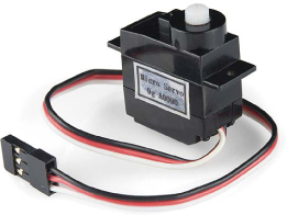
A servo motor (or just servo for short) is a special type of motor designed to rotate an arm (or horn) to a particular angle, which you will determine in your sketch. Most servo motors have a given range of 180 degrees, though some can rotate a full 360 degrees; these are called continuous rotation servos. In this project, you’ll be using a standard 180-degree hobby servo, shown in Figure 6-8.
FIGURE 6-8: A standard hobby servo
Servo motors are used in thousands of different products, from model cars and airplanes to the speedometer in your car and the robotic arms that built it.
What’s inside that black box? We opened one up so you don’t have to—see Figure 6-9.
FIGURE 6-9: The inside of a servo motor
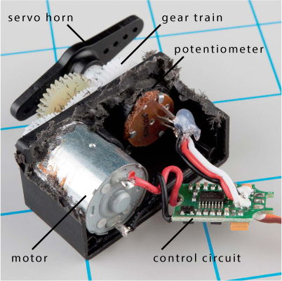
Inside a servo are three main parts: the motor, gear train, and control circuit. When voltage is applied to the motor, it turns the gear train, which turns the hub of the servo motor. The rotational position of the hub is controlled by the control circuit. Part of the gear train is a potentiometer that rotates as the motor rotates. Remember that a potentiometer is a simple sensor that changes resistance based on how much it rotates, and when it’s connected up as an adjustable voltage divider, the voltage varies as the potentiometer rotates. The control circuit reads both the value in the input signal coming into the servo (from the Arduino, in this case) and the potentiometer value and compares them. When the two values are equal, the motor stops and holds its position.
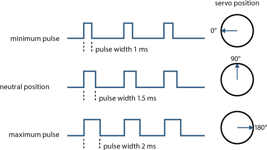
A servo motor relies on PWM, a concept we introduced in “Create More Colors with analogWrite()” on page 138. To control the position of a servo, the Arduino sends out a PWM signal that pulses every 20 ms. The width of the pulse corresponds to a specific rotational position for the servo motor. Figure 6-10 illustrates this by showing the minimum PWM pulse widths for 0 degrees of a servo, the midpoint of 90 degrees, and the maximum of 180 degrees. Similar to blinking an LED, you can use the Arduino to create a very short pulse that is on for 1 ms and off for 19 ms to move the servo to an angle of 0 degrees.
FIGURE 6-10: The PWM duty cycles for the standard range of a servo
To set the angle of a servo motor to 0 degrees, you could use code like the following:
void setup()
{
pinMode(9, OUTPUT);
}
void loop()
{
digitalWrite(9, HIGH);
delay(1);
digitalWrite(9, LOW)
delay(19);
}
This code drives pin 9 HIGH for 1 ms, and then immediately sets the pin LOW for 19 ms. As soon as the 19 ms are over, it has to drive the pin HIGH again for 1 ms to maintain the timing cycle. If your code is busy managing timing like this, you can’t add anything else to it without affecting the timing of the pulses and control of the servo. Thankfully, the Arduino has a trick to simplify the way you control the servo motor: using a library. A library is a file containing extra code that you can use with your sketch to perform specific tasks or make it easier to use particular parts. The Servo library handles all of the pulse timing needed to drive the servo motor to a specific angle.
In this project, you’ll be using the Arduino to move a balance beam based on the voltage output of a sensor—your potentiometer. The code will use the voltage reading of the sensor to set the appropriate pulse width length for a given rotation for the servo, which will determine the angle of the beam.
The good news is that the Arduino, and more specifically the Servo library, does all of the hard work for you! It is great to understand how the pulse width controls the position of the servo, but, in the end, the software takes care of it for you.
BUILD THE BALANCE BEAM PROTOTYPE
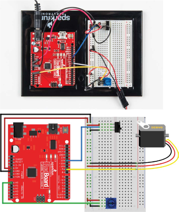
Now that you know the theory, you’ll build the circuit for the Balance Beam. You’ll start by connecting the servo, and then you’ll add a potentiometer; Figure 6-11 shows the full circuit.
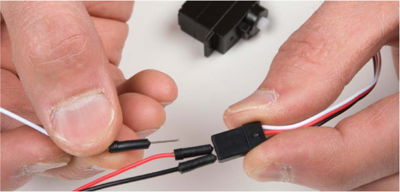
Notice that the servo has a single three-pin female header. To connect this to your circuit, you’ll need to use male-to-male jumper wires. Take three short male-to-male jumper wires and connect these to the female pins, as shown in Figure 6-12. It’s good practice to use the colors that correspond to the servo wires to make it easier to see which is which: black, red, and white represent the ground, power, and signal lines, respectively. Now, hook the servo up to the Arduino.
FIGURE 6-11: Balance Beam prototype circuit
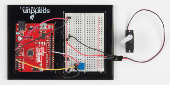
FIGURE 6-12: Adding male-to-male jumper wire extensions to the servo motor
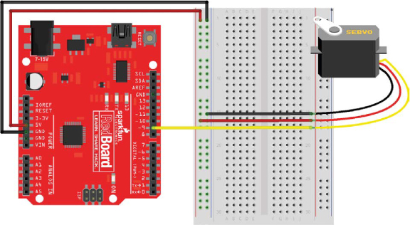
The circuit connection is pretty simple: connect 5 V and GND from the Arduino to the power rails on the left side of the breadboard. Connect the servo’s ground (black) wire to the ground rail on the breadboard and the power (red) wire to the 5 V rail. Connect the signal wire directly to pin 9 on the Arduino. A complete diagram is shown in Figure 6-13.
FIGURE 6-13: Servo hooked up to signal, power, and ground
Finally, add the servo horn onto the hub of the servo. Horns are different-shaped arms for a servo that rotate with the hub to make it easier to use and attach things to the servo. At this point, select any one of the horns that come with the servo, and press-fit it onto the hub of the servo, as shown in Figure 6-14. You will add a specific horn later, but for now we just want to make it easier to see rotation.
FIGURE 6-14: Press-fitting a servo horn from the included options
If the servo starts moving or acting erratically, simply disconnect its black wire from the ground rail to stop it. It’s good safety practice to keep the black wire disconnected until you upload code.
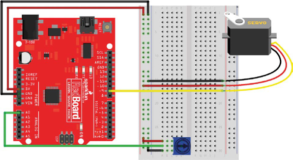
Now, wire up the potentiometer. The breadboard has plenty of room, so place the potentiometer anywhere you like, making sure each leg is in its own row. Connect the two outside pins to the 5 V and ground rails, with the center pin connected to analog input pin A0 directly on the Arduino, as shown in Figure 6-15.
FIGURE 6-15: The full Balance Beam circuit
At the moment, you just have a servo connected to a potentiometer. To give the project its balancing powers, you need to program it.
PROGRAM THE BALANCE BEAM
To use the servo with an Arduino, you need to use the Servo library— which, as mentioned earlier, is a collection of prewritten code that expands the commands and capabilities of the code in your sketch. It gives you more features and functions to work with and simplifies using external hardware with your Arduino. For example, the Servo library includes code that attaches the servo to a specific Arduino pin, moves the servo to specific angles, and even detaches the servo from a pin.
Before you program the full project, you’ll upload a quick test sketch to check that your servo is working correctly.
Test the Servo
Here’s a simple example sketch for controlling your servo. Start a new sketch by selecting File ▸ New, and then enter the sketch in Listing 6-1:
LISTING 6-1: A servo “Hello world”
➊ #include<Servo.h>
➋ Servo myServo;
void setup()
{
➌ myServo.attach(9);
}
void loop()
{
➍ myServo.write(90);
}
To use the Servo library, call #include<Servo.h> ➊, which tells the Arduino to include the Servo.h file containing the Servo library code. This adds the functions and definitions of the library to the sketch. Notice that this is one of the rare instances where there isn’t a semicolon at the end of the line. In Arduino programming, the # symbol indicates that the following code is a preprocessor directive, a special piece of code that should be executed before the rest of the sketch. When you compile a sketch, the first thing that runs is the preprocessor, which searches for any lines that start with a # symbol and don’t end with the semicolon and runs those lines first. The #include directive tells the preprocessor to include all of the code in the named file before compiling the code in your sketch.
You can also use the drop-down menu to add a library by selecting Sketch ▸ Include Library… and then selecting the library you want to use (in this case, Servo). This will automatically add the #include statement to your sketch. This option is great if you can’t remember the precise syntax of the #include command or the library name—for example, when you use a library for the first time.
The library allows you to create a type of data structure called an object. An object is simply a container for variables and functions that are predefined. Functions that are associated with the object are referred to as methods. In this sketch, the line Servo myServo; creates a new Servo object named myServo ➋.
You can give an object any name you like, but we recommend using a descriptive name, like myServo, so it’s recognizable. Now you can use that name to reference all the servo commands that are available to you in the Servo library. For example, the method myServo.attach() tells the Arduino which pin the servo is attached to. If you had multiple servos, each one would get a unique name so that you could control all of them independently.
As an example, think of a robot arm that moves at the shoulder, elbow, and wrist, using a servo for each joint. The code for it would create three Servo objects named shoulderServo, elbowServo, and wristServo so that you could position each one accurately and at a different orientation from the others. Each one of those Servo objects would have its own set of methods that you could use separately.
For the Balance Beam, you’ll use only one servo. The setup of the sketch tells the Arduino that you have a servo attached to pin 9 with the method myServo.attach(9) ➌. It then tells the Arduino to move the servo to a position of 90 degrees via the method myServo.write(90) ➍. The Servo library converts the angle in degrees of rotation to the appropriate pulse width behind the scenes. This is built into the write() method.
Now, plug the black wire of your servo into ground and upload your code to the Arduino, and the servo will rotate to 90 degrees. It’s safe for now to leave your servo wired up.
NOTE
Although the servo’s full range of motion is 180 degrees, we recommend keeping the write() value between 10 and 170 degrees, especially for servos with plastic gears. Overextending a servo’s range can do irreparable damage.
To move the servo again, just pass another number within the bounds of the servo’s range of motion (10–170) to the write() method and upload the sketch again. Play with your servo for a bit, passing in different values.
Okay, so you know how to get the servo to move just once. Now, here’s some code that really gets it moving. Listing 6-2 moves the control of the servo into a loop and repeats a motion.
LISTING 6-2: Servo blink sketch
#include<Servo.h>
Servo myServo;
void setup()
{
myServo.attach(9);
}
void loop()
{
myServo.write(10);
delay(1000);
myServo.write(170);
delay(1000);
}
This piece of code is a servo version of the blink sketch from Project 1. The servo moves to 10 degrees, waits for 1 second, moves to 170 degrees, waits for 1 second, and then repeats. We fondly refer to this as “robot march,” because when you have 20+ people doing it at once, it sounds like a robot army marching to take over the world.
Wow! You’re on a roll here. But servos really become interesting when you can control the servo yourself, without having to reprogram it each time. It’s time to get the potentiometer involved.
Complete the Balance Beam Sketch
For the final sketch, you’ll program the potentiometer to control the rotation of the servo. Modify your sketch as shown in Listing 6-3:
LISTING 6-3: Using the map() function to control a servo with a potentiometer
#include<Servo.h>
Servo myServo;
➊ int potVal;
int anglePosition;
void setup()
{
myServo.attach(9);
}
void loop()
{
potVal = analogRead(A0);
➋ anglePosition = map(potVal, 0, 1023, 10, 170);
myServo.write(anglePosition);
delay(20);
}
This sketch reads the value of the potentiometer, translates it into an angle value, and then writes that value to the servo. There are some new commands in here, so we’ll go over it step-by-step.
The top portion of this code looks just like the first two example listings. It includes the Servo library and creates a Servo object named myServo. It also declares two global variables ➊ named potVal and anglePosition. These variables will be used to store the raw value of the potentiometer and a calculated angle position for the servo, respectively.
In the loop() function, the variable potVal stores the raw analog-to-digital converter value from the analogRead(A0) function. As you turn the knob on the potentiometer, the voltage on the wiper pin will vary between 0 V and 5 V. Remember that analogRead() will convert a voltage from 0 V to 5 V to a number between 0 and 1,023. However, the values 0 to 1,023 aren’t very useful for controlling the servo. As we mentioned before, the servo needs to stay between 10 and 170 degrees.
Thankfully, Arduino has a built-in map() function that allows you to take one range of numbers and find the equivalent value in a different range. The variable anglePosition stores an angle position that is calculated from potValusing the map() function ➋. The map() function uses five parameters: map(input, fromLow, fromHigh, toLow, toHigh). In this example, it maps the value of potVal from the range of 0 to 1,023 to a new range of 10 to 170. This is a really nifty function in Arduino that makes scaling and translating between value ranges super easy!
The sketch also adds a short delay of 20 ms to give the servo enough time to move before it reads the potentiometer again. A 20 ms delay is the minimum delay that the servo needs. You may also recall that it’s the time period of the PWM signal that’s used to control the angle.
Once you have this sketch updated, upload it to your Arduino. Now when you turn the potentiometer, the servo moves with it. Pretty sweet! Next you’ll take your newfound superpower and build a balancing game out of it.
BUILD THE BALANCE BEAM
With this cool way to control a servo, we thought it would be fun to create a desktop game. You’ll create a balance beam that you control using the potentiometer and servo. A ping-pong ball will roll on the balance beam, and your goal is to get the ball as close as possible to the ends of the beam without it falling off.
Cut Out the Parts
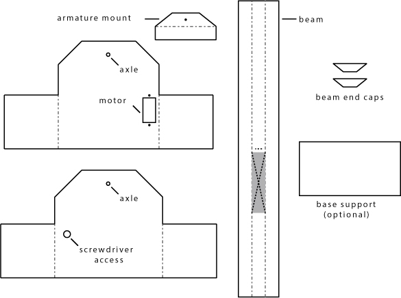
Download the template provided at https://www.nostarch.com/arduinoinventor/ (shown in Figure 6-16), print it out, and then trace it onto your cardboard. We designed this project to fit on as small a piece of cardboard as we could.
FIGURE 6-16: Balance Beam frame template (not full size)
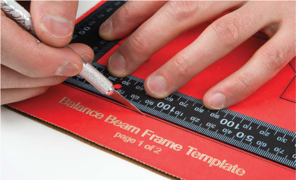
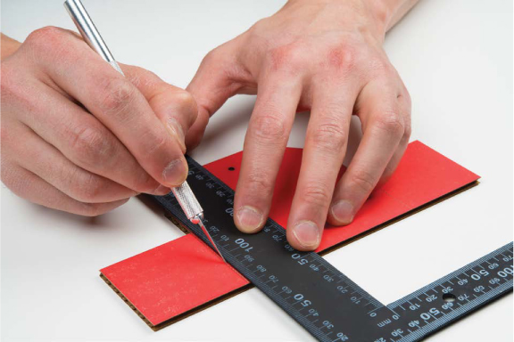
Using a craft knife, cut all the solid lines along the perimeter of each shape, as well as the cut-out for the motor mount. Don’t score any of the pieces just yet; you’ll do that as you go along. Remember to exercise safety when cutting. Use a metal ruler and a sharp craft knife, as shown in Figure 6-17, and take your time. Use a drill or a craft knife to make the six different holes in this design. If you’re using a drill, you’ll need a 1/4-inch drill bit for the screwdriver access hole, a 1/8-inch drill bit for the axle holes, and a 1/16-inch drill bit for the armature mount hole and the two motor mount holes.
FIGURE 6-17: Cutting out the frame pieces from the template
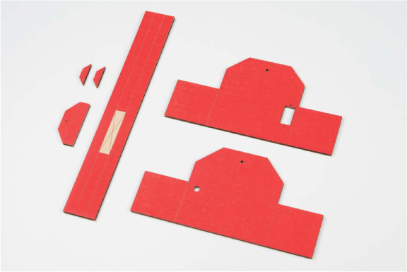
Once you’ve finished cutting, you should have six pieces like those shown in Figure 6-18.
FIGURE 6-18: All cardboard parts cut out
Build the Beam
Take the longest piece, which will be the actual beam, and carefully score the dotted line that runs along its length. This will allow you to curve the beam so that it cradles the ball. We designed the template so that the beam is 11 inches long, the length of a standard sheet of 8.5 × 11-inch paper.
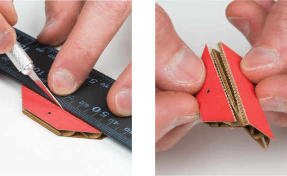
Next, prepare the armature mount. This is a small trapezoidal piece about 2 1/4 inches wide by 1 inch tall. You will use this piece to connect the servo motor to the beam. Score it and bend it into a right angle, as shown in Figure 6-19.
FIGURE 6-19: Preparing the armature mount
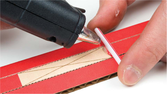
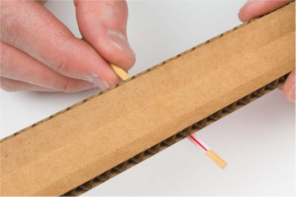
Next, cut down the drinking straw so that it’s 1 3/4 inches long, and glue it down along the center line of the beam, as shown in Figure 6-20.
FIGURE 6-20: Gluing down the straw at the midpoint of the beam
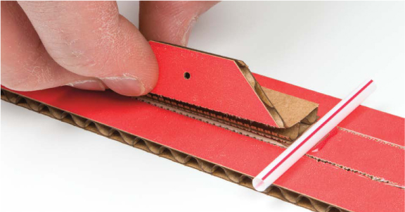
Now, glue down the half of the armature mount without the drilled hole. This goes just to the left of the drinking straw, as shown in Figure 6-21; make sure the half with the hole is facing you when the straw is at the right. This is important so that it fits with the servo mounting arm.
FIGURE 6-21: Gluing the armature mount to the beam
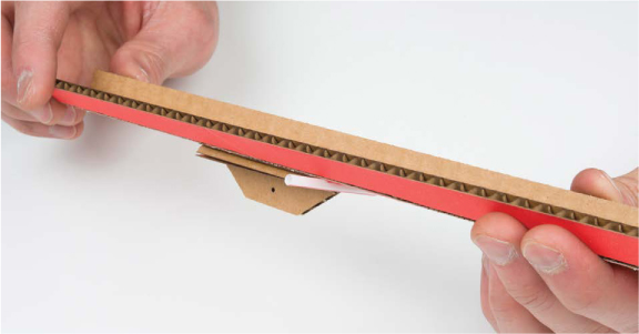
Next, bend the sides of the beam up to form a cradle that will hold the ball, as shown in Figure 6-22.
FIGURE 6-22: Bending the sides of the beam to form a cradle
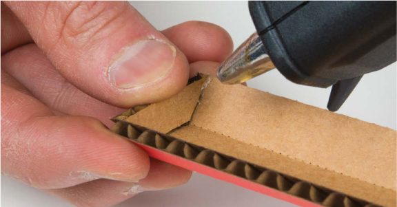
Use the smaller trapezoidal pieces to secure the ends of the beam and hold the beam together to keep the shape of the cradle. We suggest using a hot glue gun so that the pieces are secure, like in Figure 6-23.
FIGURE 6-23: Gluing the end pieces onto the beam
Next, use the wire cutters to cut down the bamboo skewer to about 3 1/4 inches. We suggest using the blunt end of the skewer. Insert the bamboo skewer into the drinking straw to form the axle for the balance beam (Figure 6-24).
FIGURE 6-24: Positioning the cut bamboo skewer so that it sticks out evenly on both sides
Build the Base and Attach the Servo
Now you’ll build the base of the balance beam. Score the sides of the base pieces, as shown in Figure 6-25, so that you can bend them into shape.
FIGURE 6-25: Scoring the sides of the base pieces
After scoring, bend the sides to form a U shape as shown in Figure 6-26. Repeat this for both pieces.
FIGURE 6-26: Bending the sides
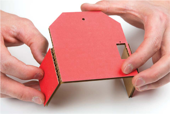
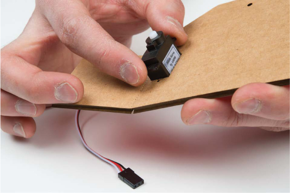
Before gluing together the base, you’ll mount the servo motor. Remove the servo motor from the breadboard circuit. There is a small, square cutout in one of the templates that should match the submicro-sized servo perfectly. Insert the servo so that the motor is facing inward, as shown in Figure 6-27.
FIGURE 6-27: Inserting the servo motor
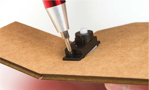
Your servo should have come with three small screws, one short and the other two longer. Use the two longer screws to secure the servo motor in place, like in Figure 6-28. If you don’t have screws, you can also use a small amount of hot glue to secure the motor.
FIGURE 6-28: Securing the servo motor in place using the two longer screws
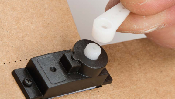
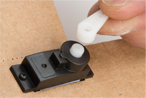
Now, select a servo horn that’s about 0.5 inches long and single sided. Gently push this into place on the end of the servo motor, as shown in Figure 6-29. Once you have it securely on the servo, orient the servo to 0 degrees. Gently rotate the servo counterclockwise with your fingers until it stops. You’ll hear the little gears inside the servo turn. Make sure that you move the servo slowly; the gears are often made of plastic and can break.
FIGURE 6-29: Attaching the single-sided servo horn
With the servo horn rotated as far as it can go counterclockwise, remove the horn and reposition it so that it is pointed straight up, as shown in Figure 6-30. This will make it easier to connect the linkage to the beam.
FIGURE 6-30: Servo horn aligned at 0 degrees
Finally, secure the horn in place using the last small screw that comes with the servo to ensure that the horn does not accidentally pop out. The horn may turn as you tighten the screw. This is okay—it won’t damage anything, but you may want to hold the servo horn in place with your fingers when tightening the screw to keep the horn from rotating. If you lost the screw, it’s not a big deal; you can leave it out and just reattach the horn if it does slip out. If you have to reposition the servo arm, you’ll need to remove this screw, which is why we included a hole on the other side of the base template.
Next, you need a linkage to connect the servo horn to the beam. To make this, you’ll shape a medium-size paper clip with a pair of needle-nose pliers. Figure 6-31 shows all the steps of this process.
FIGURE 6-31: The steps to cutting, bending, and shaping the servo linkage
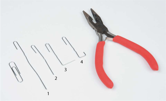
1. Use the pliers to straighten the paper clip out, leaving all but the small hook on one end.
2. Trim the paper clip down so that it is about 2 inches long from one end to the other.
3. Bend the straight end of the paper clip away from the hook at about 1 1/2 inches from the hooked end.
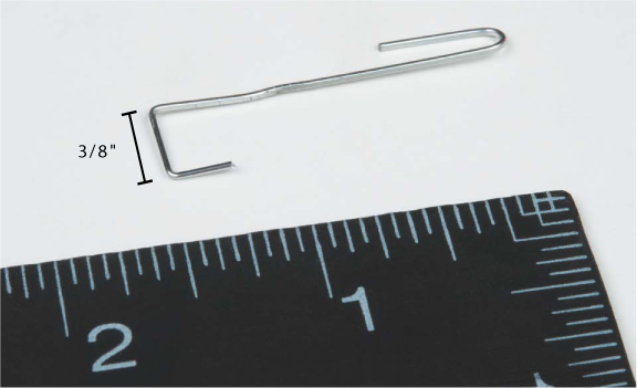
4. Add the final bend to create another hook about 3/8 inches deep. When complete, the servo linkage should be about 1 1/2 inches long (Figure 6-32). This length is perfect given the geometry of our template. If you’re designing your own enclosure, you might have to play around with this length a bit to get the servo horn connected to the beam properly.
FIGURE 6-32: Final bend in the paper clip linkage
Final Assembly
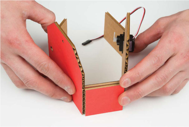
Now for the final assembly! First, glue together the two base pieces. Glue two of the square tabs together, starting with the side opposite the servo motor (Figures 6-33 and 6-34). This will give you room to get your hands in there and connect the servo horn linkage.
FIGURE 6-33: The best way to adhere two pieces together is to use a snake or S-shaped pattern with the glue.
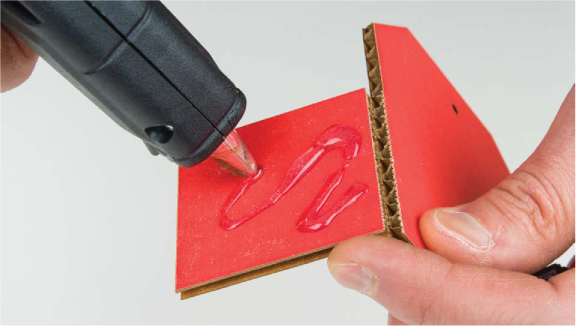
FIGURE 6-34: Secure the far side of the base first.
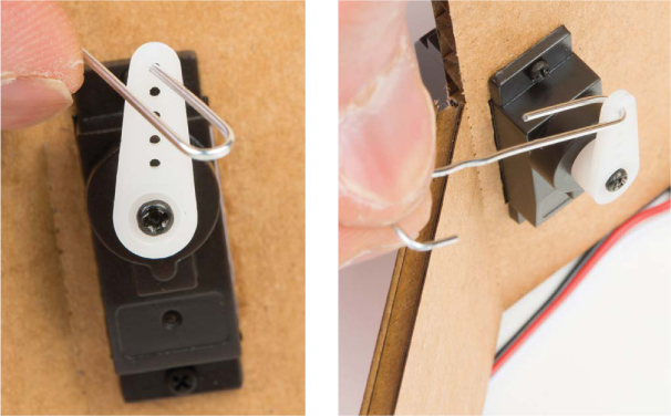
With the servo side open, take the original hooked end of the bent paper clip linkage and hook it through the last hole on the servo horn, as shown in Figure 6-35.
FIGURE 6-35: Hooking the paper clip through the last hole in the servo horn
FOUR-BAR LINKAGES AND CONNECTING SERVOS TO DO COOL THINGS
The mechanism used to turn the rotational movement of the servo horn into the up-and-down movement of the balance beam is called a four-bar linkage. We designed this template so that the length of the linkage should be about 1 1/2 inches, and it assumes that the servo horn is 1/2 inch long. We used these measurements to calculate the movements of the servo and beam. If you’re picturing circles, arcs, pivot points, and a lot of crazy geometry, don’t worry: we’ve done all the hard stuff already. The following figure shows a four-bar linkage in action, with the linkage itself and the pivot of the beam highlighted.
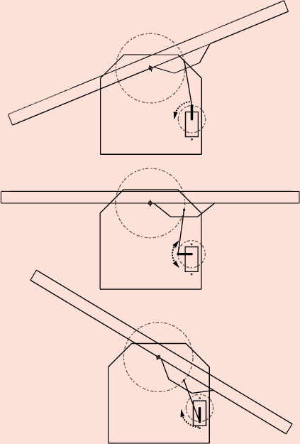
Four-bar linkages are an amazing way of converting the rotation of an object (like the servo) into a different motion (like the up-and-down motion of the beam). Engineers and roboticists use these kinds of mechanisms and linkages all the time to make things move.
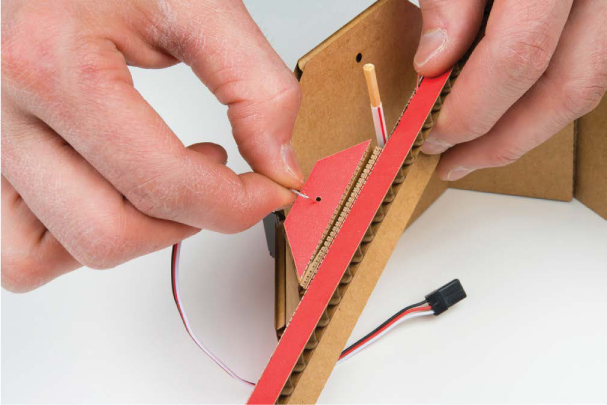
Hook the other end of the linkage through the hole in the armature mount, as shown in Figure 6-36.
FIGURE 6-36: Hooking the other end of the paper clip linkage to the armature mount
Now, insert the axle through one side of the base, carefully line up the second side, insert the axle through the matching hole, and glue the tabs at the other end of the base together (Figures 6-37 and 6-38).
FIGURE 6-37: Mounting the balance beam to the base
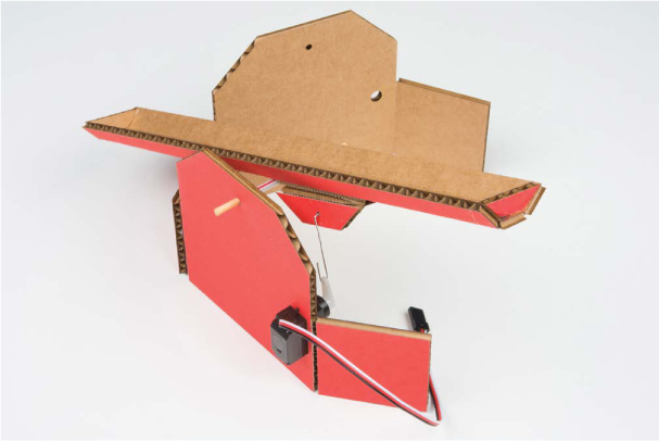
FIGURE 6-38: Completed Balance Beam project
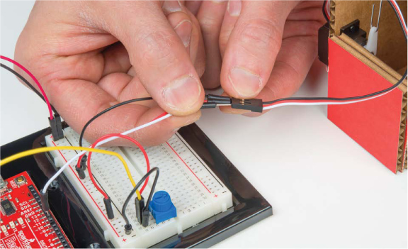
Finally, connect the servo motor back to the breadboard circuit (Figure 6-39). Power up your Arduino, and the servo motor should move into place. Turn the potentiometer and test to make sure that the linkage and the pivot points all move as expected. If they don’t, check that everything is still in place and nothing has fallen out.
As a final step, we suggest an extra rectangular base support piece. The base should measure about 2 × 3.75 inches. Insert this piece at the base of your enclosure to add extra support.
FIGURE 6-39: Reconnecting the servo motor to the breadboard circuit
With that, your project is complete! Now, find a ping-pong ball or marble and test your skills of control and precision. You now have a game to play when you should be doing something a little more productive. How many times can you roll the ball back and forth before dropping it? Challenge a friend, and see who’s better!
GOING FURTHER
This project is a great introduction to the world of servos and libraries in Arduino. There’s a lot of potential here, so we would like to share some launching points for you to play with servos.
Hack
Swap out the potentiometer with the light sensor circuit from Project 5. You’ll have to include a 10 kΩ resistor and adjust the scaling values you use. Now, move your hand up and down above the light sensor to control the ball. Go challenge a friend! Are you better with the light sensor or the potentiometer?
Modify
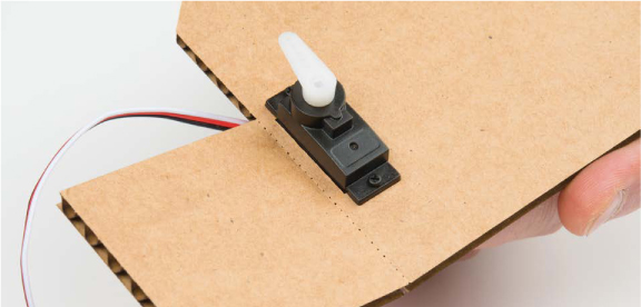
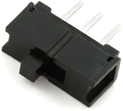
You can add an “autopilot” mode for your Balance Beam that will balance the ball on its own. To do this, you’re going to add a switch to your circuit. As you saw in Project 5, a switch is similar to a push button in that it makes or breaks a connection in a circuit, but in a switch the connection stays in place until it is switched again. The switch you’ll use is called a single-pole, double-throw (SPDT) switch, shown in Figure 6-40. This is a fancy way of saying there’s a single common pin and two options that it can be connected to. When the switch is in the leftmost position, it connects the center pin and the left pin. When the switch is in the rightmost position, it connects the center pin and the right pin.
FIGURE 6-40: The single-pole, double-throw switch
This switch, when wired correctly, will act as an on-off switch, allowing you to read whether it is set on 5 V or ground. Place the switch in the breadboard, making sure each leg gets its own row of holes. We placed ours at the top of the breadboard in Figure 6-41. As with the potentiometer, connect the two outer pins of the switch to the 5 V and ground power rails of the breadboard using two shorter jumper wires. Use a third jumper wire to connect the center pin of the switch to pin 12 of the Arduino. A complete diagram of this circuit is shown in Figure 6-41.
FIGURE 6-41: The final circuit with the mode selection switch
The center pin is the signal pin and will read either HIGH or LOW depending on the position of the switch. You’ll use this paired with some basic logic to switch between manual control, which uses the potentiometer, and autopilot, which sets the servo to move back and forth on its own.
From the book’s resources at https://www.nostarch.com/arduinoinventor/, upload the P6_AutoBalanceBeam.ino sketch to your Arduino. Take a look at the comments in the sketch to see how it works.
Remember that if the beam’s not centered when you switch autopilot on, the ball will likely fall off. It may take a few tries, but when you get it, it looks like magic! Take a look at a video of ours running here: https://www.nostarch.com/arduinoinventor/.
All materials on the site are licensed Creative Commons Attribution-Sharealike 3.0 Unported CC BY-SA 3.0 & GNU Free Documentation License (GFDL)
If you are the copyright holder of any material contained on our site and intend to remove it, please contact our site administrator for approval.
© 2016-2026 All site design rights belong to S.Y.A.