The Arduino Inventor's Guide (2017)
8 Drawbot, The Robotic Artist
As an homage to the Logo turtle project, in this project we’re going to make a Drawbot: a robot that you can program to move and draw. Logo was a programming language created in the late 1960s by Daniel G. Bobrow, Wally Feurzeig, Seymour Papert, and Cynthia Solomon. It was later adapted to support a robot with a drawing pen called a turtle (see Figure 8-1).
FIGURE 8-1: An early version of a Logo turtle
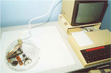
Turtles were connected to a computer to receive movement commands in the Logo language, such as fd 10 to drive forward 10 spaces. As the turtle moved, it drew with the attached pen. These Logo turtles were an early educational system designed to teach programming concepts in a visual way.
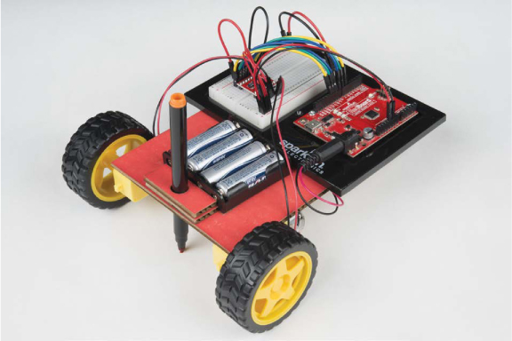
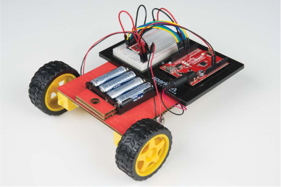
You’re going to build your own Arduino-controlled turtle, the Drawbot (Figure 8-2), which was inspired by the work of Seymour Papert and his team.
FIGURE 8-2: A completed Drawbot
MATERIALS TO GATHER
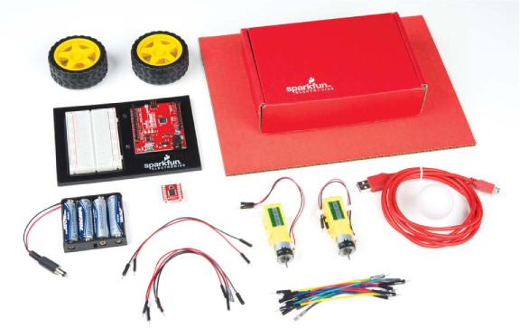
Your robot will have two wheels, each with a motor that’s controlled by the Arduino through a new component called an H-bridge. An H-bridge is a small modular circuit board similar to the transistor circuit you used in the last project, except that it will enable you to control both the speed and the direction of the motor. This will give your robot the most flexibility and control. Gather your parts (shown in Figures 8-3 and 8-4), and let’s get started!
Electronic Parts
• One SparkFun RedBoard (DEV-13975), Arduino Uno (DEV-11021), or any other Arduino-compatible board
• One USB Mini-B cable (CAB-11301 or your board’s USB cable)
• One solderless breadboard (PRT-12002)
• Two geared hobby motors (ROB-13302*)
• One TB6612FNG H-bridge motor driver (ROB-09457* unsoldered or ROB-13845* presoldered)
• Two rubber wheels fit for the geared hobby motors (ROB-13259*)
• Male-to-male jumper wires (PRT-11026)
• Male-to-female jumper wires (PRT-09140*)
• One 4 AA battery holder (PRT-09835*)
NOTE
The parts marked with an asterisk (*) do not come with the standard SparkFun Inventor’s Kit but are available in the separate add-on kit.
FIGURE 8-3: Components and materials for the Drawbot
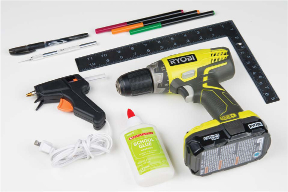
Other Materials and Tools
• Pencil
• Craft knife
• Metal ruler
• Glue (hot glue gun or craft glue)
• (Optional) Drill and 3/16-inch drill bit
• (Optional) Soldering iron
• Cardboard (about 12 inches square) or a cardboard box
• Ping-pong ball
• Enclosure template (see Figure 8-12 on page 235)
FIGURE 8-4: Recommended tools
NEW COMPONENTS
You’ll be using two new components in this project: an H-bridge motor driver and geared hobby motors. Let’s take a look at how these components work.
The H-Bridge Motor Driver Integrated Circuit
In Project 7, you used a transistor circuit to control a single motor with Arduino, which allowed you to control the speed of the motor but not the direction of its spin. In this project, you’ll use a new component called an H-bridge motor driver that will allow you to control both the speed and direction of the motor.
The H-bridge motor driver is an integrated circuit (IC) chip, made up of about a dozen transistors wired together internally inside a small plastic package. An IC chip is a prewired circuit that has been integrated into a single package to make building complex projects easier. There are many different ICs out there; one example is the brain behind the Arduino Uno, the ATMega328 chip. In this case, the H-bridge motor driver IC allows you to control a motor’s speed and direction of rotation by connecting power and just a few signal wires to the Arduino.
You might recall from Project 7 that a transistor is simply a switch that can be controlled electronically. A standard H-bridge motor driver consists of four or five transistors (or switches) wired up in an H configuration, as shown in Figure 8-5. (The motor shown in the middle isn’t included in the H-bridge IC; you’ll add that in.) By controlling which of the four main switches (labeled A–D) are open or closed, you can control the direction in which the current flows through the motor. The fifth switch (E) controls the speed of the motor’s rotation.
FIGURE 8-5: H-bridge circuit for both direction and speed control
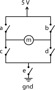
Remember that current flows from positive to negative. If you closed switches A and D, current would flow through the motor from left to right, turning the motor in one direction. If you instead closed switches B and C, current would flow through the motor from right to left, causing it to spin in the opposite direction.
Switch E is pulsed on and off rapidly through PWM (see “Create Analog Signals with PWM” on page 139). The duty cycle of this PWM signal will determine how fast the motor spins. On your robot, you’ll have two motors, each with its own H-bridge circuit, and you’ll attach a wheel to each motor so you can control its spin speed and direction.
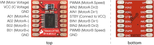
The H-bridge motor driver you’ll use in this project is the Toshiba TB6612FNG, shown in Figure 8-6. It comes as a breakout board with holes for pins that are spaced 0.100 inches apart—perfect for inserting into a breadboard.
FIGURE 8-6: TB6612FNG H-bridge motor driver breakout board (without pins soldered)
NOTE
The chip also has a standby pin that can be used to put the motor in standby mode to conserve power, but you won’t need this feature, so you’ll disable it.
The Toshiba TB6612FNG is actually a dual H-bridge IC. This means it has two full H-bridge circuits built into a little package, allowing you to control the two motors on your robot with a single board. The H-bridge distinguishes the two motors as A and B, as you can see on the underside of the board in Figure 8-6. To control each H-bridge circuit, you use three signal wires: two for direction and one for speed.
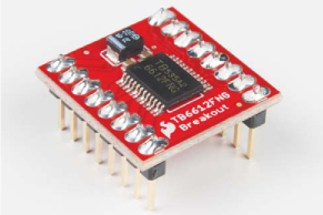
You can buy the board either with or without pins already soldered on, so if you want to save yourself the trouble of soldering, make sure you get the presoldered board (ROB-13845). If you have the board without header pins already soldered on (ROB-09457), it’s not a problem, but you’ll need to solder male headers onto the pins; for soldering instructions, see “How to Solder” on page 302. In either case, before you start building this project you should have a board that looks like Figure 8-7.
FIGURE 8-7: DEV-12211 H-bridge motor driver with headers soldered on
Geared Hobby Motor
The basic hobby motor that we used in Project 7 is great for simple mechanisms like spinning fans, but it doesn’t offer a lot of torque (rotational force). In this project, we want to use a motor to move the entire project around, so we need to use a geared motor—a motor that’s attached to a gearbox (see Figure 8-8).
FIGURE 8-8: A geared hobby motor consists of a basic motor and a gearbox
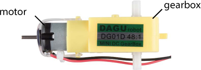
A gearbox essentially converts mechanical rotations into torque. This gearbox has a 48:1 gear reduction, which means 48 rotations of the motor equal one rotation of the output shaft. This slows down the motor by a factor of roughly 1/48 and results in a multiplication of the torque by a factor of 48. Basically, the output speed is slower, but the torque is a lot higher.
BUILD THE DRAWBOT PROTOTYPE
Now, let’s wire this up to see how it all works. You’ll connect just one motor for now to test the H-bridge motor driver, so you’ll use only one half of the dual H-bridge board. Figure 8-9 shows how the board and Arduino should be wired. The board is split horizontally, with the top half controlling Motor A and the bottom half controlling Motor B, though the power pins are used for both motors. Connect 5 V and GND from the Arduino to the power rails on the breadboard, and make sure to add a jumper wire to connect the two 5 V rails of the breadboard so you can use either rail to give power; this will save you from crossing too many wires and keep your board neat.
FIGURE 8-9: H-bridge test circuit
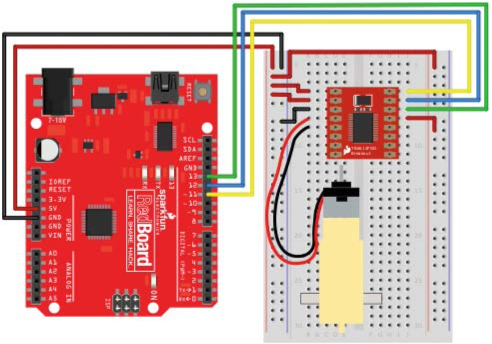
Starting from the top left of the H-bridge, connect 5 V to the top two pins, VM and VCC. VM controls the power for the motors, and VCC controls the power for the chip. Next, use a jumper wire to connect one of the chip’s GND pins to the GND rail of the breadboard. There are three pins available for ground on the H-bridge, as you can see in Figure 8-7, and you can use any of these.
Next you’ll connect the motor. The motor has two wires: red and black. The orientation of the wires doesn’t actually matter, but for consistency connect the red wire to the pin labeled A01 and the black wire to pin A02.
The remaining pins on the left side are those for controlling the second motor and another GND pin, so leave them for now. The pins on the top right of the H-bridge breakout board are for the signal wire connections for Motor A. The topmost pin, labeled PWMA, controls the motor’s speed. Connect this to pin 11 on the Arduino. (Remember that pins 3, 5, 6, 9, 10, and 11 all have PWM capability and can be used with the analogWrite() function.)
The next two pins, labeled AIN2 and AIN1, are used to control the direction and drive of Motor A, which you can do by setting these pins to different combinations of HIGH and LOW. Table 8-1 shows the combinations. Connect AIN2 to Arduino pin 12 and AIN1 to Arduino pin 11.
TABLE 8-1: H-bridge motor controller functions
|
AIN1 |
AIN2 |
FUNCTION |
|
HIGH |
LOW |
Clockwise |
|
LOW |
HIGH |
Counterclockwise |
|
HIGH |
HIGH |
Electronic brake (see note) |
|
LOW |
LOW |
Stop/coast |
NOTE
Setting both pins HIGH will employ electronic braking. The two wires of the motor are essentially shorted together, causing the motor’s spinning to stop abruptly. By contrast, setting both to LOW would just stop actively spinning the motors, meaning the wheels would coast to a stop rather than stopping deliberately.
Lastly you’ll need to disable the STBY pin. As mentioned earlier, this H-bridge IC has a standby pin that allows you to put the chip into a low-power sleep mode, which is useful for applications where power consumption is a concern. For this project, you don’t need this feature, so you’ll disable it. This chip is designed with STBY as an active low input. This means that when this pin is LOW, it goes into standby mode. To disable standby, you’ll connect this pin directly to 5 V on the power rail.
PROGRAM THE DRAWBOT
Let’s start the sketch with a little test. This simple example will spin the motor clockwise slowly for 1 second, change directions and spin counterclockwise quickly for 1 second, and then stop for 1 second before starting again. Open the Arduino IDE, and copy the code in Listing 8-1 into your window. When you’re done, click Upload and watch what happens!
LISTING 8-1: H-bridge motor controller example of speed and direction control
➊ const byte AIN1 = 13;
const byte AIN2 = 12;
const byte PWMA = 11;
void setup()
{
pinMode(AIN1, OUTPUT);
pinMode(AIN2, OUTPUT);
pinMode(PWMA, OUTPUT);
}
void loop()
{
//set direction to clockwise
➋ digitalWrite(AIN1, HIGH);
digitalWrite(AIN2, LOW);
➌ analogWrite(PWMA, 50);
delay(1000);
//set direction to counterclockwise
➍ digitalWrite(AIN1, LOW);
digitalWrite(AIN2, HIGH);
analogWrite(PWMA, 255);
delay(1000);
//brake
➎ digitalWrite(AIN1, HIGH);
digitalWrite(AIN2, HIGH);
delay(1000);
}
The sketch starts with a new data type: const byte ➊. The keyword const is used to declare a constant, which is like a variable but with a value that can’t be changed again later in the code. Thus, constants are useful for declaring things that will stay the same throughout the code, like pin numbers or configurations. In this case, these constants define the pin numbers that control the H-bridge. Since the pin numbers are numbers between 0 and 13, you can define these constants as the data type byte.
NOTE
Most of the time it doesn’t matter too much whether you use a constant or a variable, but constants use less memory on the Arduino, so it’s good practice to use them when you can, and you may see them used in other people’s examples online. Also, while it’s not a hard-and-fast rule, constant names are typically in all capital letters.
Next, you set the pins as outputs, and then set the direction you want the motor to spin using two digitalWrite() functions ➋ on pins AIN1 and AIN2. The first loop block sets AIN1 to HIGH and AIN2 to LOW, which spins the motor clockwise. To set the speed, you use an analogWrite() function ➌ on the PWMA pin. You may recall from Project 5 that you can use analogWrite() to set an analog pin to a PWM value from 0 to 255; the value given here, 50, is relatively slow. The motor will spin for 1 second because of delay(1000), and the next loop block changes directions with two more digitalWrite() functions ➍. Here the sketch simply swaps which pin is HIGH and which is LOW, sets the speed to 255 with analogWrite(), and adds another delay(1000) to set it to spin for 1 second.
The last part of the sketch sets both AIN1 and AIN2 to HIGH ➎, with another delay(1000). This applies an electronic brake and stops the motor for 1 second before the loop begins again and repeats the pattern.
Using this code as an example, you can now control both the speed and direction of a motor with just three lines of code! But we can make this even simpler. Let’s clean up the code by using custom functions.
Create a Custom Function
At the moment, every time you want to control the motor you’re using three lines of code: two to control the direction and one to set the speed. In this section you’ll make a custom function that will take just one number to determine both the direction and the speed of the spin. This number can be anything between -255 and 255 and will spin the motor clockwise if the number is positive and counterclockwise if it’s negative. Add the code in Listing 8-2 to the very end of your sketch.
LISTING 8-2: Custom function to set the motor speed of Motor A
void ➊setMotorA(➋int motorSpeed)
{
➌ if (motorSpeed > 0)
{
digitalWrite(AIN1, HIGH);
digitalWrite(AIN2, LOW);
}
➍ else if (motorSpeed < 0)
{
digitalWrite(AIN1, LOW);
digitalWrite(AIN2, HIGH);
}
➎ else
{
digitalWrite(AIN1, HIGH);
digitalWrite(AIN2, HIGH);
}
➏ analogWrite(PWMA, abs(motorSpeed));
}
Name the function setMotorA() ➊. This function uses a number as a single argument named motorSpeed ➋ to set the motor’s speed. First, a simple if() statement determines whether the number is positive or negative by checking whether motorSpeed is greater or less than zero. If motorSpeed is positive ➌, the if() statement sets the direction pins so that the motor spins clockwise. If it’s negative ➍, an else if() statement sets the direction pins to spin the motor counterclockwise. If it’s neither positive nor negative (that is, if it’s 0), a final else statement ➎ sets both direction pins HIGH to apply the brake and stop the motor.
The line at ➏ uses the abs() mathematical function to find the absolute value of motorSpeed. The analogWrite() function sets the speed of the motor, but it works only with values from 0 to 255. The abs() function makes sure that the positive part, or absolute magnitude, of motorSpeed is used to set the speed.
Clean Up the Code
Now, let’s clean up the loop() with this new function. You can see in Listing 8-3 that the loop() code is much shorter and easier to read. Make these changes to the loop() in your sketch and upload it to your board. It should behave the same way as before. Now, if you want to set the motor to a different speed or direction, you can do it with just a single line of code!
LISTING 8-3: Simplified version of the loop() using the custom function setMotorA()
void loop()
{
//set direction to clockwise
setMotorA(100);
delay(1000);
//set direction to counterclockwise
setMotorA(-255);
delay(1000);
//stop
setMotorA(0);
delay(1000);
}
This code sets a setMotorA() value and a delay to make each change in speed and direction. Now you have the beginnings of your Drawbot! Next, you’ll wire the second motor.
WIRE THE SECOND MOTOR
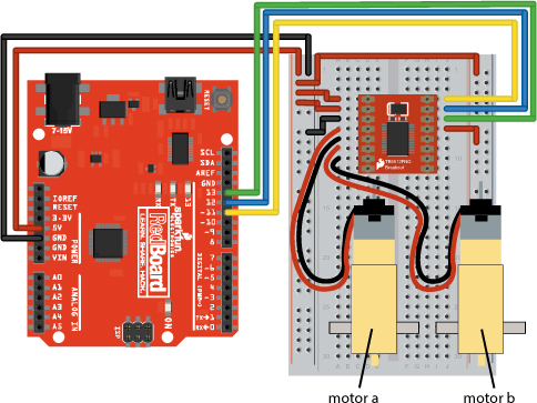
The DrawBot needs a second motor so it can zip around on two wheels. Figure 8-10 shows how the second motor will be wired. Plug Motor B in on the left side of the breakout board just below the connections for the first motor, with the red wire connected to B02 and the black wire connected to B01. Next, add the signal control lines to the H-bridge breakout board, just below the STBY pin on the right side. Connect the PWMB pin on the H-bridge to Arduino pin 10 for speed control, and connect the BIN1 and BIN2 pins to Arduino pins 8 and 9, respectively, for direction control.
FIGURE 8-10: Wiring diagram for the motor driver and two motors
Now, you’ll need to add code to control the second motor, as shown in Listing 8-4.
LISTING 8-4: Adding constants and pinMode() functions for Motor B
const byte AIN1 = 13;
const byte AIN2 = 12;
const byte PWMA = 11;
➊ const byte BIN1 = 8;
const byte BIN2 = 9;
const byte PWMB = 10;
void setup()
{
pinMode(AIN1, OUTPUT);
pinMode(AIN2, OUTPUT);
pinMode(PWMA, OUTPUT);
➋ pinMode(BIN1, OUTPUT);
pinMode(BIN2, OUTPUT);
pinMode(PWMB, OUTPUT);
}
This code adds the three additional constants ➊ for the signal control pins for Motor B, and sets each of these pins as OUTPUT ➋ in the setup().
Next, you’ll again write a custom function to control Motor B. This code is so similar to the setMotorA() function that you can save yourself some typing by highlighting the code for setMotorA(), copying it (CTRL-C), pasting it (CTRL-V) below the setMotorA() function, and changing the As to Bs. This is a technique that programmers use a lot, and it can save you a lot of time. You just need to make sure you’re careful to change all the As to Bs in this second custom function (Listing 8-5), or the code won’t work.
LISTING 8-5: Custom function for Motor B
void setMotorB(int motorSpeed)
{
if (motorSpeed > 0)
{
digitalWrite(BIN1, HIGH);
digitalWrite(BIN2, LOW);
}
else if (motorSpeed < 0)
{
digitalWrite(BIN1, LOW);
digitalWrite(BIN2, HIGH);
}
else
{
digitalWrite(BIN1, HIGH);
digitalWrite(BIN2, HIGH);
}
analogWrite(PWMB, abs(motorSpeed));
}
The sketch will now need motorSpeed values for both setMotorA() and setMotorB(). Let’s add those to test the motors out together.
DRIVE BOTH MOTORS
To make your Drawbot drive forward, you’ll need the right motor to spin clockwise and the left motor to spin counterclockwise. This may seem counterintuitive, but take a look at a robot base from the side. Figure 8-11 shows a robot frame from both sides with arrows indicating the forward direction.
FIGURE 8-11: Side views of the robot from the right and left sides. To move forward, the right wheel must spin clockwise and the left wheel must spin counterclockwise.
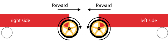
On the right side of the robot, the wheel needs to spin clockwise for the robot to move forward, but on the left side of the robot, the wheel needs to spin counterclockwise. Pay attention to the direction in which each axle is spinning. If you need to, attach a piece of masking tape to the spinning end of the motor so that you can see the axle’s direction.
Now, to make the robot go backward, you just reverse those directions. After adding the custom function code for setMotorB() to your sketch, adjust your loop() to look like Listing 8-6, and then upload this code and watch your motors spin!
LISTING 8-6: New loop() code to test both motors
void loop()
{
//drive forward medium speed for one second
setMotorA(100);
setMotorB(-100);
delay(1000)
//drive backward quickly for one second
setMotorA(-255);
setMotorB(255);
delay(1000);
//stop for one second
setMotorA(0);
setMotorB(0);
delay(1000);
}
You should see that Motor A (right side) is spinning clockwise and Motor B (left side) is spinning counterclockwise, and then after 1 second they flip. If you find that the motors are spinning in the same direction, swap the red and black wire connections on one of the motors.
With just a few lines of code, you can make your Drawbot move forward, turn right, turn left, move backward, and jiggle around!
Now it’s time to build a frame or a chassis for your Drawbot. Because the code you wrote is all in the loop() part of the sketch, your motors will continue to spin, stop, spin, and stop. To stop the motors from spinning while you’re building the chassis for your Drawbot, temporarily disconnect the USB cable from your computer.
BUILD THE DRAWBOT CHASSIS
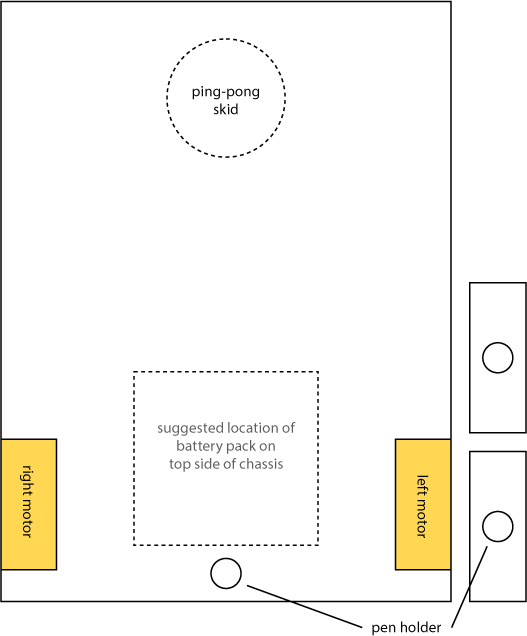
If you’re using the SIK with the breadboard holder and Arduino baseplate, you’ll need to make the chassis of the Drawbot at least as large as the baseplate itself. The baseplate measures 6 inches by 4.25 inches. Use a piece of cardboard or thin plywood to make your chassis. For our design, we made the chassis a rectangular 6 × 8-inch cutout, as shown in Figure 8-12. You can download a PDF of this template from https://www.nostarch.com/arduinoinventor/.
FIGURE 8-12: Drawbot chassis, bottom view (not full size)
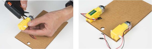
Using tape or a hot glue gun, attach the motors to the underside of the chassis, oriented as shown in Figure 8-13, with the motor hub near the back and the longer end of the motor body toward the front. (Hot glue is a great semipermanent method for attaching things because you can simply scrape it away with a craft knife and remove the part if you want to reuse it later.) You may need to temporarily disconnect the motors from your breadboard circuit while you’re attaching them to the chassis, so just remember to reconnect them to the circuit after you’ve glued them down. Refer back to Figure 8-10 if you need help rewiring it.
FIGURE 8-13: Attaching the motors to the chassis with hot glue
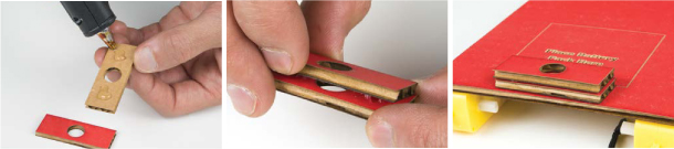
We have a hole in our base template that’s designed for a pen or marker. A Drawbot needs to be able to draw, after all! To give the pen more stability, we glued two smaller pieces of cardboard together to create a taller pen holder. Glue these pieces down right on top of the hole, as shown in Figure 8-14.
FIGURE 8-14: Gluing the pen holder onto the chassis
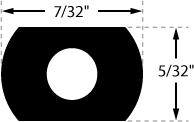
Finally, attach the wheels to the motors. You’ll notice that the motor axles have two flat edges (Figure 8-15). Make sure you line these up with the flat edges on the axle holes of the wheels. The fit may be a little tight. Hold on to the entire motor while pushing the wheel on so that you don’t accidentally rip the motor off your chassis.
FIGURE 8-15: Profile of motor axle. Line up the flat edges with the flats of the opening on the wheel.
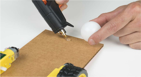
The Drawbot will move around using the two motor wheels as power and steering and a skid caster at the other end for balance. This method is called differential steering. This particular Drawbot is designed as a front-wheel-drive system, using a ping-pong ball as a skid caster in the back. As the Drawbot moves around, it will skid the ping-pong ball over the surface. Glue the ping-pong ball into place as shown in Figure 8-16, trying to center it as much as possible for the best balance.
NOTE
If you want to make your own wheels, use the shape and dimensions in Figure 8-15 for the axle holes.
FIGURE 8-16: Attaching a ping-pong ball as a skid caster
Now, set the breadboard holder, the Arduino, and a battery pack on top of the chassis, as shown in Figure 8-17. Use a little bit of tape or dabs of glue to make sure they don’t move around.
FIGURE 8-17: The breadboard holder, the Arduino, and a battery pack on the cardboard chassis
Test and Troubleshoot
Reconnect the USB cable to your Arduino board or plug in your battery pack and watch what happens. You might need to hold on to the cable so that it doesn’t get tangled up. The robot should move forward slowly for 1 second, reverse direction quickly for 1 second, and then stop for 1 second. Because all of your code is in the loop(), the Drawbot will repeat this motion over and over again until you disconnect it from power. While you’re working on tweaking your code, you may want to put the Drawbot’s back end up on a few books to keep the wheels from touching the table.
Now, if your robot doesn’t behave like you expect it to, you’ll need to do a little troubleshooting to figure out what’s going on. First, identify the problem. There are two common problems that we’ve seen with this bot: moving in the wrong direction and turning in circles. If it moves backward first instead of forward, switch the red and black wires for both motors going to the H-bridge. If your robot moves in circles instead of moving forward or backward, try flipping the motor wires on either Motor A or Motor B—don’t flip both of them, or you’ll get the same problem again. You should now have a Drawbot that moves forward and then backward, stops, and repeats this motion.
Before moving on, test how far the Drawbot moves in 1 second and make a note of this. You’ll add a marker pen for it to start drawing lines, and you may need to adjust the speeds and the times so that the Drawbot is easier to control. Slower speeds and shorter times might be best if you’re working on a small table.
Turn and Make Patterns: A Robot Square Dance
Now that you’ve mastered moving your robot forward and backward, see what fun patterns you can make with your new creation. Before you put a marker onto your Drawbot, try turning corners.
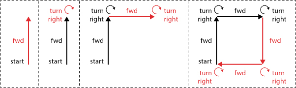
To turn the robot to the right, both motors need to spin counterclockwise, and to turn the robot left, they need to spin clockwise. See if you can get your Drawbot to do a little square dance! To draw a square, the basic steps are as follows:
• Move forward.
• Turn 90 degrees.
• Move forward.
• Turn 90 degrees.
• Move forward.
• Turn 90 degrees.
• Move forward.
• Turn 90 degrees.
Figure 8-18 illustrates the steps needed. You’ll notice that you repeat the same steps four times. You already know you can use a loop() for repeated actions, but loops repeat forever, and you want your Drawbot to stop after four turns. Luckily there’s a programming technique that’s perfect for repeating a part of the code a set number of times: a for() loop.
FIGURE 8-18: Steps to a simple square dance
A for() loop starts with the command for, followed by a set of parentheses. Inside the parentheses there are three sections. See Listing 8-7.
LISTING 8-7: The for() loop
for(➊int count = 0; ➋count < 4; ➌count++)
{
➍ //insert code here that you want to repeat
}
The first part ➊ is the declaration and initialization of a counter variable that keeps track of repetitions of the loop. You declare this variable as an integer, name it count, and initialize it to 0. You can name this variable anything you want, so long as you use the same variable name in the next two parts. The next part is the condition statement ➋, which controls whether the for() loop continues to repeat or stops. Here, you continue repeating as long as the condition statement count < 4 is true. Since count was initialized at 0, this condition is true on the first pass, and the loop will repeat. The third part is the increment statement ➌, which tells the for() loop what to do with the counter variable after each repetition. Here, count++ is a shorthand for count = count + 1. This increments the counter variable by 1 for each repetition. The final part ➍ is the code that you want to repeat or loop through, like any code you place inside curly brackets.
So in all, the for() loop’s arguments are saying that the loop should continue to run until it’s run four times, at which point the count will be incremented to 4, the condition statement will be false, and the loop will exit. The for() loop is a really handy way to clean up code and repeat instructions a particular number of times.
Now, use this new skill to write your square dance code. Replace the loop() in your sketch with the loop() in Listing 8-8. Everything else will stay the same.
LISTING 8-8: Square dance code
void loop()
{
➊ for(int count = 0; count < 4; count++)
{
//drive forward
➋ setMotorA(100);
setMotorB(-100);
➌ delay(500);
//turn right
➍ setMotorA(-100);
setMotorB(-100);
delay(250);
}
➎ delay(1000);
}
SHORTHAND FOR QUICKLY MANIPULATING VARIABLES
Often you may want to increment, decrement, or just modify the value of a variable in code. The most common use is to increment the value of a variable by one for each repetition of a loop, which you can do with the code variableName = variableName + 1. But there are also a few shorthand methods to modify values of variables, shown in the following table.
|
SHORTHAND CODE |
LONGHAND CODE |
DESCRIPTION |
|
variableName++; |
variableName = variableName + 1; |
Increment by 1 |
|
variableName += 2; |
variableName = variableName + 2; |
Increment by 2 |
|
variableName += n; |
variableName = variableName + n; |
Increment by n |
|
variableName--; |
variableName = variableName - 1; |
Decrement by 1 |
|
variableName -= 2; |
variableName = variableName - 2; |
Decrement by 2 |
|
variableName -= n; |
variableName + variableName - n; |
Decrement by n |
|
variableName *= n; |
variableName = variableName * n; |
Multiply by n |
|
variableName /= n; |
variableName = variableName / n; |
Divide by n |
To draw a square, the sketch uses the for() loop ➊ to repeat the steps four times. The robot first drives forward ➋ for just half a second ➌. You want to make sure that it doesn’t go too far and draw all over your floors. Next, to turn the robot, the sketch sets both motors to spin counterclockwise ➍. To complete each square, you add a short, 1-second delay ➎. Notice that the delay is after the curly bracket for the for() loop. The Drawbot will repeat the steps—move forward and turn four times—and then wait for 1 second before the whole loop() repeats. This will give you a chance to manually move the Drawbot or reposition it if you need to. The values in this code worked well in our office, but you may need to fine-tune and play around with the speed settings and timing for your own Drawbot. Tweak your sketch until you get your Drawbot moving in a square-like pattern. Don’t worry if it’s not perfect—just keep testing out the speeds of the corner turns. This is part of the art you’ll be creating!
We’ve included the full sketch for the square-dancing Drawbot in Listing 8-9.
LISTING 8-9: Complete Drawbot square dance code
const byte AIN1 = 13;
const byte AIN2 = 12;
const byte PWMA = 11;
const byte BIN1 = 8;
const byte BIN2 = 9;
const byte PWMB = 10;
void setup()
{
pinMode(AIN1, OUTPUT);
pinMode(AIN2, OUTPUT);
pinMode(PWMA, OUTPUT);
pinMode(BIN1, OUTPUT);
pinMode(BIN2, OUTPUT);
pinMode(PWMB, OUTPUT);
}
void loop()
{
for(int count = 0; count < 4; count++)
{
//drive forward
setMotorA(100);
setMotorB(-100);
delay(500);
//turn right
setMotorA(-100);
setMotorB(-100);
delay(250);
}
delay(1000);
}
void setMotorA(int motorSpeed)
{
if (motorSpeed > 0)
{
digitalWrite(AIN1, HIGH);
digitalWrite(AIN2, LOW);
}
else if (motorSpeed < 0)
{
digitalWrite(AIN1, LOW);
digitalWrite(AIN2, HIGH);
}
else
{
digitalWrite(AIN1, LOW);
digitalWrite(AIN2, LOW);
}
analogWrite(PWMA, abs(motorSpeed));
}
void setMotorB(int motorSpeed)
{
if (motorSpeed > 0)
{
digitalWrite(BIN1, HIGH);
digitalWrite(BIN2, LOW);
}
else if (motorSpeed < 0)
{
digitalWrite(BIN1, LOW);
digitalWrite(BIN2, HIGH);
}
else
{
digitalWrite(BIN1, LOW);
digitalWrite(BIN2, LOW);
}
analogWrite(PWMB, abs(motorSpeed));
}
As we mentioned earlier, the chassis template includes a notch on the front end to place a marker. We suggest using either a washable or dry-erase marker. Find a large piece of poster paper or dry-erase board that you can lay on the floor. Be really careful not to draw all over your floor! It might get you in trouble. (Trust us, we’ve made this mistake before, and we definitely regret it.)
Place your Drawbot on the drawing surface. Use a piece of masking tape to secure the marker in place, positioning it so that it makes good contact with the drawing surface. Move the Drawbot around manually on the drawing surface to test the marker placement. Now, plug the USB cable in to your computer and watch what happens. Be quick to grab the Drawbot if it looks like it’s going to run off your drawing surface and onto the floor.
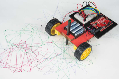
To mix things up, change marker colors or modify your code to draw different size squares. See if you can make your Drawbot draw spirals and stars! Figure 8-19 shows some of the fun patterns our Drawbot made in our office.
FIGURE 8-19: Drawbot in action—make sure you use a large piece of paper to keep it from drawing all over the floor!
If you want to add some style to your Drawbot, try digging through your craft supplies or finding some spare cardboard and see what you can come up with. We placed an old pretzel jar container on our Drawbot at the office. It’s now called Pretzel Bot, and it drives around and gives away free pretzels (Figure 8-20).
FIGURE 8-20: Pretzel Bot! The Arduino and breadboard are hidden inside the box.

GOING FURTHER
The Drawbot is an introduction to basic robotics. The simplest robots are really just a controller and two motors, and that’s what you have here. We’ll give you a few ideas to take it to the next level.
Hack
Preprogrammed motion is fun, but every time you want to change up the pattern, you have to reupload the sketch. But with some changes to the code, you can use the Serial Monitor to control your Drawbot while it’s still going.
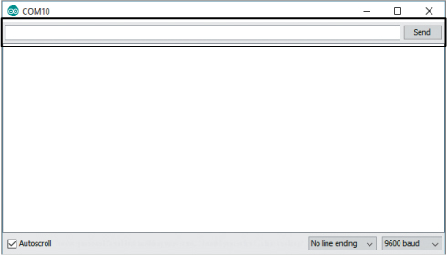
So far, you’ve used the Serial Monitor only to read data the Arduino sends back to the computer as the project is working, such as sensor data, but the Serial Monitor can also send data to the Arduino. Open the Serial Monitor window, and you’ll see a small text box at the top with a button labeled Send, as shown in Figure 8-21. This box allows you to send data to the Arduino so you can control it from the Serial Monitor.
FIGURE 8-21: Serial Monitor window
The P8_DrawbotSerial.ino sketch (downloadable from https://www.nostarch.com/arduinoinventor/) uses the Serial Monitor to send just three numbers to control Motor A, Motor B, and the driving time.
Take a look at the code. This new sketch declares three variables to hold the speed of Motor A, the speed of Motor B, and the delay time, which are the three numbers you send. You initialize communication with the Arduino with Serial.begin(9600); to send and receive data using the Serial Monitor. The Arduino reads the data you put into the Serial Monitor and assigns any integers to the three speedA, speedB, and delayTime variables, which are then used for the familiar setMotorA(), setMotorB(), and delay() functions. See the comments in the code for a more complete explanation.
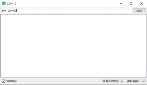
Upload the sketch to your Drawbot, open the Serial Monitor, enter 100 -100 500, and press ENTER or click Send (see Figure 8-22). The Drawbot should move forward for half a second and then stop. Now you can fine-tune your Drawbot routines without having to reupload the code each time! The code will run once and doesn’t repeat unless you give it additional commands. What happens when you enter six numbers, such as 100 -100 500 -100 -100 250? See if you can choreograph a dance routine that is represented by a sequence of numbers.
FIGURE 8-22: Choreographing a robo-dance
Modify
What other shapes can you program your Drawbot to create? Use what you learned with for() loops and see if you can hack your code to make it draw a triangle or star. You’ll have to do some experimenting to get the timing and speeds just right. What happens when you move just one wheel at a time?
Bonus
There’s a bonus script (at https://www.nostarch.com/arduinoinventor/) that will let you control the turtle with even simpler commands, like fd 10 and bk 10 to move forward or backward 10 spaces. Download P8_BonusTurtle.ino and load it into your IDE. Then open your Serial Monitor and enter a few of the following commands: fd 10 to move forward 10 spaces, bk 10 to move backward 10 spaces, rt 90 to turn right 90 degrees, and lt 90 to turn left 90 degrees. See if you can instruct your new turtle to do a square dance with these instructions!
All materials on the site are licensed Creative Commons Attribution-Sharealike 3.0 Unported CC BY-SA 3.0 & GNU Free Documentation License (GFDL)
If you are the copyright holder of any material contained on our site and intend to remove it, please contact our site administrator for approval.
© 2016-2026 All site design rights belong to S.Y.A.