Professional Embedded ARM Development (2014)
Part I. ARM Systems and Development
Chapter 5. First Steps
WHAT’S IN THIS CHAPTER?
Setting up a cross-compile environment
Your first ARM program
Running an ARM program in a simulator
Presenting some evaluation boards
Running a program on an evaluation board
WROX.COM CODE DOWNLOADS FOR THIS CHAPTER
The wrox.com code downloads for this chapter are found at www.wrox.com/go/profembeddedarmdev on the Download Code tab. The code for this chapter is divided into the following major examples:
hw-code.zip
hw2-code.zip
The time has come to start working. The first task consists of installing everything needed to compile for an ARM processor. By default, a development computer can compile code for itself; for example, a Linux i7 PC can compile code that runs on an x86 Linux system. You probably need something different; a cross compiler. A cross compiler is a compiler that can create executable code for a platform other than the one on which the compiler is run. My personal development machine is an i7, so to compile code for an ARM system, I needed to install a cross compiler.
Sourcery CodeBench Lite is a free cross compiler available from its website. Download the Embedded Application Binary Interface (EABI) version, and install it on your development PC. The Lite versions are available at http://www.mentor.com/embedded-software/sourcery-tools/sourcery-codebench/evaluations/.
Sourcery CodeBench Lite comes with a multitude of programs; most starting with arm-eabi. Don’t be frightened by all the programs; you will use a few, but not all of them. It also comes with a complete documentation explaining their use.
For the first steps, you will be compiling code for an ARM926EJ-S, which used to be a reference for embedded ARM platforms. You could, of course, have chosen just about any ARM core available, but the ARM9 core is a good choice for the tools available, since qemu has support for an entire board, called the Versatile. Newer projects should not use Classic ARM processors; they should use the newer Cortex processors. However, the Versatile board is an excellent resource for learning. The previous Versatile board has been superseded by the newer Versatile Express boards.
You can also compile these examples for other processors.
HELLO WORLD!
Traditionally, the first program anyone writes in a new language or on a new computer is Hello, world!, which is a program that outputs “Hello, world” onto a display device. Because it is typically one of the simplest programs possible in most programming languages, it is by tradition often used to illustrate to beginners the most basic syntax of a programming language, or to verify that a language or system is operating correctly. In embedded systems, this is sometimes tricky because you do not necessarily have a display, but there are other means. You can write out your text onto a serial port, but remember that when a system first starts, there are no drivers. To write any text onto a serial port, you must first initialize the device and create a driver, which is out of the scope of this book.
This example creates a barebones system using the absolute minimum. This system will not require any interrupt handlers or cache management, and therefore it will not be used. It is a basic program that you can add to later. The basic C routine looks like the following and is called hw-entry.c(code file: hw-code.zip):
int entry(void)
{
return 0;
}
The routine isn’t called “main” by choice because when writing a program using “main,” you can presume that most of the hardware is initialized, which is not the case here. Some hardware might be initialized in assembly, but other components will be initialized in C. This is one possible use of the entry function, an entry point from assembly to C.
Now compile that, like you would with any C routine. You need to cross compile your program; by using traditional tools, you can build a binary that would work on your current development platform: probably an x86. You want to compile your routine for an ARM processor and specifically an ARM926EJ-S.
arm-none-eabi-gcc -c -mcpu=arm926ej-s entry.c -o entry.o
This command compiles entry.c into entry.o, using ARM instructions. You aren’t done here — far from it. As explained previously, this is not a program that will be run inside an operating system, but this is a program run directly onto a processor with nothing else running. It is a bare metal application, meaning that you need to set everything up in assembly.
Of course, your C routine will be called from assembly, and before running your routine, you need to set some things up, notably the vector table. This is what the assembly file, called hw-startup.s (code file: hw-code.zip), will look like:
.section INTERRUPT_VECTOR, "x"
.global _Reset
_Reset:
B Reset_Handler /* Reset */
B . /* Undefined */
B . /* SWI */
B . /* Prefetch Abort */
B . /* Data Abort */
B . /* reserved */
B . /* IRQ */
B . /* FIQ */
Reset_Handler:
LDR sp, =stack_top
BL entry
B .
Specify that the section is called INTERRUPT_VECTOR, and that it contains executable code. The vector table is called _Reset; you need this later to specify exactly where you want this code. Because you need the vector table to be at location 0x0, you can specify that later.
The vector table contains jump instructions, and in this case, you have specified only one. The function Reset_Handler will be called whenever a Reset exception occurs. All other exception vectors point to themselves; you don’t need them yet. Even if you aren’t using them, it is always good practice to write the entire table. The reset handler sets up only the stack pointer and then calls your C routine. When the C routine returns, the final branch instruction branches to itself, putting the processor into a state of limbo.
Now assemble the assembly file.
arm-none-eabi-as -mcpu=arm926ej-s hw-startup.s -o hw-startup.o
Again, you aren’t quite finished. You now have compiled parts of your program, but when creating a bare metal program, there are other things you need to specify. You need to tell your linker where everything will go in memory. Of course, your vector table has to go to a specific memory address, and to do that, you need to create an LD file. The LD file, or linker file, is a text file containing the memory architecture. You can specify where certain parts of the code are to be placed. You can reserve space and then set another memory location. That is exactly what you need to do. Put the reset vector at 0x0, reserve 4 kilobytes of memory for the .data section, the .bss section. and the stack. Finally, it then initializes the stack pointer. This is the content of the file hw-boot.ld.
ENTRY(_Reset)
SECTIONS
{
. = 0x0;
.text : {
hw-startup.o (INTERRUPT_VECTOR)
*(.text)
}
.data : { *(.data) }
.bss : { *(.bss COMMON) }
. = ALIGN(8);
. = . + 0x1000; /* 4kB of stack memory */
stack_top = .;
}
Now that you have created your file, you can tell your linker to mix all those files together.
arm-none-eabi-ld -T hw-boot.ld hw-entry.o hw-startup.o -o hw-boot.elf
This goes and creates an ELF file, but you aren’t finished yet. You go more into ELF in the next section, but in short, ELF contains much more than simple binary; it contains memory positions, possible debug names, and sections. When you run a Linux binary, you are actually loading an ELF into RAM, where the header contains important information about how to load the binary, where to place it, how much memory you will require, and so on. A bare metal system has no such requirements because you will be specifying everything. Also, you do not yet have an operating system that could parse the information; you need a real binary. To obtain a binary from an ELF file, you need to use objcopy. And specify that you want a binary output, with the –O option. This command strips all the ELF information and leaves you with the bare minimum, exactly what you need for your system.
arm-none-eabi-objcopy -O binary hw-boot.elf hw-boot.bin
This creates a file for you: boot.bin. Congratulations, you have just created your first ARM executable! And not just any program; this is a program that correctly sets up a vector table and an entry point. This is the basis for every embedded application on ARM. The next step will be to initialize hardware or to run an application, but first it is time to see exactly what has been done.
Each source file has been “compiled,” that is to say it has been transformed into an object file. A linker combines one or more object files into an executable file, optionally reading in a file that defines memory locations. Finally, objcopy “strips” the ELF headers, converting the program into a binary file that can be run directly on the processor. This is illustrated in Figure 5-1.
FIGURE 5-1: Compiling and Linking
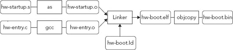
All of these source files are available in the ZIP file called hw-code.zip.
TAKING THE WORLD APART
So what exactly have you done? The compiler and linker have done their magic and created a file, but it is difficult to know exactly what they have done. What you have actually done is created an ELF file. An ELF file, short for Executable and Linkable Format, is a file that contains more than just the bare metal program. It also contains debugging information, and you can use this to peek inside.
Now check to see what you have built. By “dumping” the information held in the ELF file, you can verify what you have done. The application readelf is a program available on most development systems, and CodeSourcery supplies a version if none are available on your system. ARM also supplies a series of excellent tools, and their version is called fromelf.
The -A option prints out architecture specific details.
readelf -A hw-boot.elf
Attribute Section: aeabi
File Attributes
Tag_CPU_name: "ARM926EJ-S"
Tag_CPU_arch: v5TEJ
Tag_ARM_ISA_use: Yes
Tag_THUMB_ISA_use: Thumb-1
Tag_ABI_PCS_wchar_t: 4
Tag_ABI_FP_denormal: Needed
Tag_ABI_FP_exceptions: Needed
Tag_ABI_FP_number_model: IEEE 754
Tag_ABI_align_needed: 8-byte
Tag_ABI_enum_size: small
The Tag_CPU_name field tells you that this ELF file has been compiled for an ARM926EJ-S processor, exactly what you wanted. The following information also tells you exactly why it was important to specify the processor — and not just try to compile for a generic ARM. This is important for optimizations, and it also lets the compiler verify that everything you write is supported on this processor. The Tag_CPU_arch is v5TEJ. This means the target processor is a v5 architecture. “T” means that this processor supports the Thumb instruction set; “E” means that this processor contains Enhanced DSP instructions; and “J” means that the processor also supports Jazelle DBX. For more information, see the ARM Naming Convention section in Chapter 1.
The vector table needs to be at the address 0x0, so look at the binary that you just created. By “dumping” your ELF file, you can disassemble the file and take a closer look. This is where objdump comes in. The command from the CodeSourcery suite is called arm-none-eabi-objdump. Specify that you want to disassemble with the -d option.
This is what my output looks like this:
hw- boot.elf: file format elf32-littlearm
Disassembly of section .text:
00000000 <_Reset>:
0: ea000006 b 20 <Reset_Handler>
4: eafffffe b 4 <_Reset+0x4>
8: eafffffe b 8 <_Reset+0x8>
c: eafffffe b c <_Reset+0xc>
10: eafffffe b 10 <_Reset+0x10>
14: eafffffe b 14 <_Reset+0x14>
18: eafffffe b 18 <_Reset+0x18>
1c: eafffffe b 1c <_Reset+0x1c>
00000020 <Reset_Handler>:
20: e59fd004 ldr sp, [pc, #4] ; 2c <Reset_Handler+0xc>
24: eb000001 bl 30 <entry>
28: eafffffe b 28 <Reset_Handler+0x8>
2c: 00001050 .word 0x00001050
00000030 <entry>:
30: e52db004 push {fp} ; (str fp, [sp, #-4]!)
34: e28db000 add fp, sp, #0
38: e3a03000 mov r3, #0
3c: e1a00003 mov r0, r3
40: e28bd000 add sp, fp, #0
44: e8bd0800 ldmfd sp!, {fp}
48: e12fff1e bx lr
In this example, you can clearly see that the vector table has been placed at 0x00000000, called _Reset. Now look at the first line.
0: ea000006 b 20 <Reset_Handler>
This is the instruction at address 0x0. ea000006 is the hexadecimal dump; it is what you would find if you took a hex dump of the memory. Fortunately, you don’t have to decode that by hand; the disassembler does it for you. The instruction is B, or branch. It branches to the address 0x20, which as you can see later in the code, is the address of Reset_Handler. To help you, the disassembler also writes the name of the address, or the closest name possible with an offset. For the next instruction, the Undefined Instruction vector, the branch address is Reset_Handler + 0x4, which in this case is0x4.
So, the table has been set up, but there is one problem. How do you put this on to your system? And what happens when you turn the power off and then back on? It would be extremely complicated to be forced to manually reflash your device every time you turn on your TV or telephone, but the chances are that they use ARM processors, so the same boot sequence applies. Well, that all depends on your system.
Normally, the first few kilobytes of memory are located in read-only memory, or ROM. Sometimes, this is programmable ROM, sometimes not; it all depends on your needs. So when your system starts, it reads in the vector table from ROM and then probably runs some code from the ROM. This is known as a bootloader, and its job is to make sure that your main application (or system) can boot. Your application, or firmware, might be on another type of ROM, or maybe even on an external SD. The bootloader will do everything necessary to load that code into memory before executing it.
Bootloaders sometimes have a second function, known as recovery. In the case of a bad software update, the bootloader might detect a faulty firmware, or at least be forced into a special mode to reflash the firmware. This is often the case with mobiles phones; in the case of a faulty upgrade, the mobile telephone will no longer boot. By pressing a special (often hidden) key sequence, the firmware opens a serial connection and waits for a new firmware.
HELLO WORLD, FOR REAL THIS TIME!
Unless you have an ARM system ready, the previous example will be difficult to use. Fortunately, there are alternatives. However, they do have drawbacks. Qemu is an excellent open source program that emulates several systems, including several ARM systems. However, it is mainly used for running kernels, not fully embedded systems. When running qemu with the –kernel option, qemu loads a binary but places it at position 0x10000, not 0x0. The vector table still exists, but you cannot load a binary image into 0x0.
On a normal computer system, the kernel is loaded fairly “late.” On a desktop or laptop computer system, when you first turn it on, some implementation of BIOS runs. The BIOS checks basic configuration: system memory, sets some timers, initializes PCI express devices, and so on. The list of things to do is rather long. When that is done, it then looks for a suitable boot medium. It might be a hard drive, a USB disk, a CD-ROM, to name but a few. If it finds valid code, it loads that code into memory before executing it. This code, often called a bootloader, is responsible for low-level checks and initialization before running a kernel. On PC systems, GRUB2 and LILO are examples of boot loaders. For embedded systems, U-Boot is well known.
Qemu has its own bootloader, one that you cannot change. It does most of the hardware initialization and then expects you to supply a kernel, one that will be loaded into address 0x10000. From here on, you have two options. One is to simply ignore the vector table and load the binary straight into 0x10000. The other is to keep the vector table but to load it into 0x10000. Because the first entry of the vector table is a jump instruction, this should be transparent.
Qemu can emulate several systems, including the Versatile Platform Baseboard. The Versatile/PB is a complete system, based on an ARM926EJ-S core and also includes four UART ports. You can use this functionality to test a binary and to finally see your Hello, world!
From the Versatile/PB documentation, you can see the UART0 address is 0x101f1000. Qemu can be run with an option to display the output of UART0 directly as a terminal. The Qemu implementation of the Versatile/PB system automatically initializes some of the hardware, including the serial port. However, not all systems will do this, and indeed it is good practice to fully initialize hardware before attempting to use it. Your code will be minimal, but only for this system. For a real embedded system, you would need more code to initialize the baud rate, set some registers, and also to check that the output buffer is not full. On this simplified system, you don’t need to, and you will take advantage of that.
The hw2-entry.c file looks like this (code file: hw2-code.zip):
volatile unsigned char * const UART0_PTR = (unsigned char *)0x101f1000;
void print_uart0(const char *string)
{
while (*string != '\0')
{
*UART0_PTR = *string;
string++;
}
}
int entry(void)
{
print_uart0("Hello, world!\n");
return 0;
}
You have added two things here. First, the address of your serial port register used to send data. Second, you have added a routine that outputs your string to a serial device, character by character. Yes, UART devices are that simple. That’s why they are so often used for debugging. Modern PCs might be trying to get rid of “legacy” components such as serial ports, but embedded systems laboratories are full of them.
Now compile your C file. Use the ARM version of GCC.
arm-none-eabi-gcc -g -c -mcpu=arm926ej-s hw2-entry.c -o hw2-entry.o
By using the ARM GCC compiler, you can compile your C program into ARM assembly code.
Also, because your start address will be 0x10000, and because you will not be putting your binary directly into the vector table, you will not use a vector table. You change your assembly file to call your C routine directly. You can always add to that later, changing the vector table as needed. This brings a question; because you don’t need a vector table, why do you go through all the effort of creating a memory map? Why can’t you just compile a file and let the system load it? There are several reasons. When you create a program for an operating system, for example Linux, Windows, or MacOS, you don’t need to specify the memory location of the application. This is because the compiler looks for a specific function, main, and automatically compiles a program to start at a specific address. The operating system handles all the tasks involved: virtual memory, clearing memory space, and loading a program into a specific address before handing control over to the new program. However, on a bare metal system, there is no operating system present capable of doing the work; you have to do it. Because you know that Qemu expects a binary file present at 0x10000, you have to specify to your program that it will start at that address.
There is another reason for this. When the processor executes a jump instruction, you are telling the processor to change the PC to a specific address. Although you can use relative addresses, it is often much easier just to specify a specific memory location. If you compiled your program for a different memory address, on your first jump, the PC would have an incorrect value, and the rest of the program would be unpredictable.
In the meantime, start with a basic file. This is what your qemuboot.ld file will look like:
ENTRY(_MyApp)
SECTIONS
{
. = 0x10000;
.startup . : { startup.o(.text) }
.text : { *(.text) }
.data : { *(.data) }
.bss : { *(.bss COMMON) }
. = ALIGN(8);
. = . + 0x1000; /* 4kB of stack memory */
stack_top = .;
}
By using this file, you place the contents of startup.o at memory location 0x10000, where Qemu will be waiting for a binary file. After your program, you will reserve some space for the .data section, the .bss section, and some stack space.
Now for the startup.s file:
.global _MyApp
_MyApp:
LDR sp, =stack_top
BL entry
B .
Assemble this with an ARM assembler.
arm-none-eabi-as -g -mcpu=arm926ej-s startup.s -o startup.o
Now that you have assembled your code, you need to link the two files together using the memory map.
arm-none-eabi-ld -T qemuboot.ld entry.o startup.o -o qemuboot.elf
Just as before, this creates an ELF file, but you need to strip the ELF contents.
arm-none-eabi-objcopy -O binary qemuboot.elf qemuboot.bin
For the final part: You have compiled your bare metal program, and now you can run it inside Qemu. Configure Qemu to use the Versatile board, and ignore any graphics. All you want is the serial output.
qemu-system-arm -M versatilepb -nographic -kernel qemuboot.bin
There may be some warnings about different hardware problems that you can ignore. Qemu doesn’t emulate only a simple ARM board; you can run entire operating systems on it, complete with sound and video. According to your system, there might be different warnings about initializing sound systems. You can ignore these.
If all goes well, Qemu displays your “Hello, world!” on the screen.
SOFTWARE IMPLEMENTATION
Depending on the ARM core, some will implement hardware units for certain functions, others will rely on software. For example: division. In any project, sooner or later, the code will have to divide. The only problem is that some previous ARM cores cannot perform hardware division.
Consider the following simple helper routine:
int mydiv(int a, int b)
{
return a/b;
}
This is an extremely simple routine, and it isn’t something that is normally coded, but it serves as an example. The compiler doesn’t know what a and b will be, so it will have to create a routine that can divide any signed integer. To compile it, you can use the following:
arm-none-eabi-gcc -c -mcpu=arm926ej-s ./div.c
arm-none-eabi-objdump -S div.o
This is the output on my development computer:
Disassembly of section .text:
00000000 <intdiv>:
0: e92d4800 push {fp, lr}
4: e28db004 add fp, sp, #4
8: e24dd008 sub sp, sp, #8
c: e50b0008 str r0, [fp, #-8]
10: e50b100c str r1, [fp, #-12]
14: e51b0008 ldr r0, [fp, #-8]
18: e51b100c ldr r1, [fp, #-12]
1c: ebfffffe bl 0 <__aeabi_idiv>
20: e1a03000 mov r3, r0
24: e1a00003 mov r0, r3
28: e24bd004 sub sp, fp, #4
2c: e8bd8800 pop {fp, pc}
The compiler did indeed compile the code, but not quite as expected. What is this mysterious __aeabi_idiv? It isn’t part of the project; it is a helper class available in the GNU Compiler Collection and also from ARM directly for users of the ARM compiler. Even though this code isn’t a complete project, and it will print out a warning, it is still compilable. Well, almost.
arm-none-eabi-ld div.o -o div.elf
arm-none-eabi-ld: warning: cannot find entry symbol _start; defaulting to 00008000
div.o: In function 'intdiv':
div.c:(.text+0x1c): undefined reference to '__aeabi_idiv'
The first warning is normal. This isn’t a project; you don’t have an entry point. The compiler is doing the best it can, but it can’t do everything. The second warning is slightly more worrying. The compiler can’t find the function '__aeabi_idiv' and therefore cannot continue. The problem is, you didn’t want a function called '__aeabi_idiv', you just wanted to make a simple division. The short answer is, you can’t. This particular ARM core does not support hardware division.
This is where libraries come in. Because this core cannot natively divide, it makes use of software libraries. More recent cores do support hardware division, and a library call would have been replaced by a simple SDIV assembly instruction. For example, compile the same code for a Cortex-A15:
arm-none-eabi-gcc -c -mcpu=cortex-a15 ./div.c
arm-none-eabi-objdump -S div.o
00000000 <intdiv>:
0: e52db004 push {fp} ; (str fp, [sp, #-4]!)
4: e28db000 add fp, sp, #0
8: e24dd00c sub sp, sp, #12
c: e50b0008 str r0, [fp, #-8]
10: e50b100c str r1, [fp, #-12]
14: e51b2008 ldr r2, [fp, #-8]
18: e51b300c ldr r3, [fp, #-12]
1c: e713f312 sdiv r3, r2, r3
20: e1a00003 mov r0, r3
24: e28bd000 add sp, fp, #0
28: e8bd0800 ldmfd sp!, {fp}
2c: e12fff1e bx lr
MEMORY MAPPING
Upon RESET, an ARM core automatically deactivates the MMU, if present. Any memory fetches will directly fetch that portion of memory. That might sound strange, but there are cases in which this isn’t practical.
More advanced processors come with a specific bootloader, a small application that runs on RESET. The bootloaders generally come directly from the manufacturer and cannot be modified or deactivated. They normally enable basic tasks, like uploading a new binary in case of flash corruption or security checks to see if a valid binary is present before executing it.
For example, the reset vectors are often placed in ROM, not in RAM. Also, from a hardware point of view, RAM is not always located in the same place. A system may require placing the DDR2 controller at 0x90000000, but your software actually wants memory to start at 0x20000000. On some systems, there may be two DDR2 chips, and their memory locations might not be adjacent. To simplify this, the MMU must be configured.
The Memory Management Unit (MMU) is embedded into some ARM cores, and its primary job is to translate virtual memory to physical memory. Physical memory is what is actually physically present on the memory bus, and virtual memory is what the processor sees. When accessing memory, the processor requests a certain memory access. This access is sent to the MMU, which analyzes the request. The processor has requested memory at 0x2000F080, thinking that it is talking to DDR memory, but what it actually wants is the memory location at 0x9000F080, so give that to it instead. The processor has no idea of the change that has been done; as far as it is concerned, it has fetched the memory at 0x2000F080. Figure 5-2 shows the MMU on an ARM system. The ARM processor makes a request for a memory address, and the MMU receives the request, looks at the Translation Table, and if required, translates the memory address. The result is fed straight back to the processor.
FIGURE 5-2: MMU and memory requests
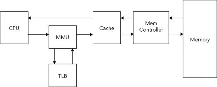
MMUs do not map only memory; they can also police access rights. An MMU can be programmed to refuse access to a certain portion of memory and can configure which portions of memory are cached.
Without going into too much detail about the different uses for virtual memory, one of the most common starting memory maps is the flat map, where virtual memory is the same as physical memory. It is a good starting point; it enables setting up memory access rights and cache.
The first thing to do is to know where to put the translation tables. A translation table is a zone in physical memory that contains the different translations. A translation table contains translation entries, and for this example, the only entry that will be used is the L1 entry.
To load the address, you need to program the CP15.
LDR r0, tlb_l1_base
MCR p15, 0, r0, c2, c0, 0
The variable tlb_l1_base can be defined as follows:
tlb_l1_base:
.word 0x00008000
By writing this, you define tlb_l1_base as a 32-bit value. The instruction mcr is short for Move to Coprocessor from ARM Register. Coprocessor instructions cannot use variables or fixed values; they can transfer only to and from ARM registers.
The first part has been done; the MMU now knows where the page data will be stored, but of course, the page data still has to be populated. That will be the next part of the program.
The Translation Table is full of Translation Entries, and as said earlier, for simplicity, I will use only L1 tables. The mapping will be flat; virtual memory = physical memory. Because L1 entries define 1 megabyte of memory, and because ARM processors can access 4096 megabytes of memory, you need 4096 section entries. Table 5.1 defines a section entry.
TABLE 5-1: Section Entry Layout
|
BITS |
DESCRIPTION |
|
31:20 |
Section base address |
|
11:10 |
Access permissions |
|
8:5 |
Domain |
|
3:2 |
Cacheable/Bufferable |
|
1:0 |
0b10 for section page table entry |
Undefined bits should be left as zero. The part that will interest you the most is the Section base address. For flat mapping, you will define that 0x000xxxxx will map to 0x000xxxxx, all the way to 0xfffxxxxx that will map to 0xfffxxxxx. So that is exactly what your loop is going to do. As for the other bits, the Access permissions will be 0x11; meaning that both supervisor and user code can access the memory.
LDR r0,=tlb_l1_base
MOVT r1, #0x0000
MOVW r1, #0x0C02 ; Full access, domain 0, no cache, page table entry
MOV r2, #4095 ; The number of entries to do, minus one
mmuloop:
STR r1, [r0] ; Store the contents of r1 into the translation table
ADD r0, #4 ; Next entry
ADD r1, #0x00100000 ; Next page
SUBS r2, #1
BNE mmuloop
done:
This small program starts by loading the address of the translation table into r0. The first page table entry is loaded into r1, and kept, because all pages will use the same parameters for now. Then, r2 is loaded with the value 4096, or the amount of entries to load into the translation table.
The mmuloop section is easy to understand. First, the value held in r1 is saved into the memory location pointed to by the value in r0 — the first table entry. The register r0 is then incremented by 4 because section entries are 32 bits long. It now contains the next address in the table. The register r1is then incremented by 0x00100000, or the size of a section. Finally, r2 is decreased by 1, and the routine loops if the value of r2 is not equal to zero. If it is equal to zero, then the program continues.
The MMU now knows about the base address, and the table has been populated, but there is still one more thing left to do — activate the MMU. The following code does just that:
MRC p15, 0, r0, c1, c0, 0
ORR r0, r0, #0x1
MCR p15, 0, r0, c1, c0, 0
Just like the previous coprocessor example, this small portion of code updates the MMU registers, but it first reads from the coprocessor. MRC will read a coprocessor register into an ARM register. Next, a logical OR is performed, setting the first bit to one. Then, the updated register is put back into the coprocessor.
Congratulations, the MMU is now activated!
REAL WORLD EXAMPLES
Theory can be fun, but the real fun is in trying applications on real-world systems. Some people are often frightened about purchasing an ARM system, mainly because of the price. Indeed, some high-end evaluation boards can be expensive, but they are often used for specific tasks: prototyping a next-gen telephone, or for testing multicore environments. Most people don’t know that a complete ARM system can be purchased for less than $50, together with all the tools needed to start a project.
This section presents three evaluation boards: Silicon Labs’ STK3800 and STK3200, and Atmel’s SAM D20 Xplained Pro.
Silicon Labs STK3800
ARM cores are not born equal. Because ARM licenses the technology, customers are allowed a certain degree of liberty, greatly enhancing the ARM ecosystem. Some clients modify the core to integrate more or less cache, others to be faster. Silicon Labs specializes in low-power devices and creates some of the most energy-efficient Cortex-M chips available on the market.
The Cortex-M series has always been well known for its exceptionally low power usage, but there are some cases in which a Cortex-M will consume just a little bit more energy, especially in high temperature environments. Silicon Labs has spent a lot of time and energy perfecting an already impressive design, and the result is the Gecko series.
Silicon Labs’ line of Gecko chips also come with exceptionally well-designed evaluation boards, equipped with numerous sensors that enable the end user to experiment freely. When the time has come to do a little more experimentation with external components, the board is equipped with solder points so that users can incorporate their own inputs and outputs. Also of note, these boards have a built-in hardware debugger, allowing developers to debug, to flash, and to profile code.
The Wonder Gecko STK3800 board integrates a Cortex-M4 with a Floating Point Unit (FPU), and two user buttons, one light sensor, one metal detector, a full-size LCD screen with numerous information displays, and something that is not found often on boards, a touch-sensitive sensor. All this comes with all the cables needed to function, two USB ports (one for debugging and one available as I/O), as well as a CD containing some interesting applications to flash test programs and to also show real-time power consumption. The board is shown in Figure 5-3.
FIGURE 5-3: Silicon Lab’s STK3800 Evaluation Board
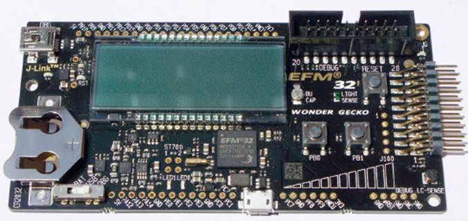
To show just a fraction of what this board can do, I’ll create a desk clock. The STK3800 board comes with a battery connector, allowing the board to be powered by a single CR2032 battery. Therefore, the board can be mobile, and the battery lasts longer than you’d first think. When the battery does run out, the EFM32 has yet another trick up its sleeve; the STK3800 has a super capacitor that can not only keep critical sections of the processor powered, but it also allows the board to keep RTC time; in this application it can keep time for up to 8 hours.
The clock will be event-driven, meaning that the Wonder Gecko will spend most of its time sleeping, therefore saving energy. The Wonder Gecko will wake up and respond to interrupts, but which ones exactly? I’ll create a program that shows only hours and minutes, so in theory that means only one interrupt a minute, but what about screen animation? The LCD display comes with a circular widget, something that would be ideal to tell the user that the system is still working. Again, the Wonder Gecko series has another trick; the LCD controller can actually do basic animations without help from the MCU.
The entire program will be separated into several stages: first, basic system initialization. For debugging, the application also initializes trace output. This can be removed later in the production stage.
After the basics have been set up, the application needs to do further configuration; core frequency, the LCD controller, and the real-time clock all need to be set up. After that is done, the GPIO will be configured for interrupts.
After all the initialization and configuration is done, it is time to run the real code; the clock itself.
Initialization
Initialization is a work that can frighten a lot of people. In theory, it means low-level system configuration: setting up the cache, preparing any system devices before entering your application. Remember that Cortex-M chips are designed to be “simple,” both architecturally and for developers. Cortex-M programs can be designed entirely in C, but Silicon Labs makes it even easier. The time has come to initialize the processor.
/* Chip errata */
CHIP_Init();
And that’s it. No, really. Due to some differences between chips, Silicon Labs created the CHIP_Init() function to set all the reset registers to the latest version of documentation. This keeps things nice and simple. Now that the chip itself is initialized, the power and code profiler can optionally be activated.
/* Enable the profiler */
BSP_TraceProfilerSetup();
Now, values can be read from the debug port, indicating power usage, a listing of which interrupts cause a change of state and the time they took. Next, you ensure that the core frequency has been updated.
/* Ensure core frequency has been updated */
SystemCoreClockUpdate();
For a clock application, you must initialize the LCD display.
/* Initialize LCD display with no voltage boost */
SegmentLCD_Init(false);
With four simple lines in C, the EFM32 is set up and ready to go.
Configuration
You want to save as much energy as possible, and for that, the processor must spend most of its time in a low power state. Instead of looping continuously, you will program the RTC to wake the processor every minute to update the LCD screen. After the processor awakens, you update a few variables and then go back to sleep. First, you need to configure the RTC.
1 void rtc_setup(void)
2 {
3 RTC_Init_TypeDef rtcInit = RTC_INIT_DEFAULT;
4 CMU_ClockEnable(cmuClock_CORELE, true);
5 CMU_ClockSelectSet(cmuClock_LFA, cmuSelect_LFXO);
6 CMU_ClockDivSet(cmuClock_RTC, cmuClkDiv_32);
7 CMU_ClockEnable(cmuClock_RTC, true);
8 rtcInit.enable = false;
9 rtcInit.debugRun = false;
10 rtcInit.comp0top = true;
11 RTC_Init(&rtcInit);
12 /* Schedule an interrupt every minute */
13 RTC_CompareSet(0, ((RTC_FREQ / 32 ) * 60 ) - 1;
14 /* Enable Interrupts */
15 NVIC_EnableIRQ(RTC_IRQn);
16 RTC_IntEnable(RTC_IEN_COMP0);
17 /* Enable the RTC */
18 RTC_Enable(true);
19 }
This merits a little bit of explanation. First, on line 3, you create a default RTC structure. Then, the Clock Management Unit is set to use a clock divider of 32, to save power, before activating the CMU.
Now you are ready to configure the RTC. Set it so that it is not enabled by default, and also so that it is halted on debug, making it easier for you if you need to run the application step by step.
The RTC_CompareSet instruction on line 13 is where a comparison register is set up. You will set it up for exactly 60 seconds, so every minute it will trigger an interrupt, which is what is configured in the next lines. Finally, when everything is set up, the RTC is enabled.
In just a few lines of code, the RTC and the CMU have been configured, and your application is almost ready. When an interrupt triggers, it will call a function called RTC_IRQHandler. This is what the source will look like:
1 void RTC_IRQHandler(void)
2 {
3 RTC_IntClear(RTC_IFC_COMP0); /* Clear the interrupt source */
4 minutes++; /* Increment minutes by one */
5 if (minutes > 59)
6 {
7 minutes = 0;
8 hours++;
9 if (hours > 23)
10 {
11 hours = 0;
12 }
13 }
14 }
When an interrupt occurs, first, you need to clear the interrupt source. Then the minutes variable is incremented, incrementing the hours as needed.
Main Application
The main application will be incredibly simple. A small loop will keep running in a while(1) structure, update the LCD screen, and then return to sleep mode.
while(1)
{
SegmentLCD_Number(hours * 100 + minutes);
EMU_EnterEM2(true);
}
The SegmentLCD_Number routine simply updates the LCD screen with the requested number; in this case, the time. Then, the processor is put into Energy Mode 2.
EFM32 chips have five energy modes, from 0 to 4. In Mode 2, the ARM core is powered down, and certain low power devices are still powered, including the LCD display and the RTC. Energy Modes 3 and 4 provide even more energy conservation but disable the RTC, which would need external support. Energy Mode 0 is normal operation, and this is the state to which the processor returns when an interrupt occurs.
Because the processor is put into sleep mode as soon as the LCD is updated, the LCD update routine is run only once per minute, meaning the processor spends almost all its time sleeping, conserving energy.
If the result is so energy efficient, just how long would that last? Well, Silicon Labs has a solution for that, too. They provide an application that inputs data from the different states. You will be spending approximately 1 minute in EM2, and just to be on the safe side, you can say that you will be spending 1 millisecond in EM0. In reality, the few routines present execute much faster than that, but it is always worth considering the worst-case scenario. If your clients have to change batteries every 2 weeks, they are not going to like your product. Running this in the Silicon Labs energyAware Battery software indicates that the problem is actually going to be the opposite; you had better make battery replacement easy, not because it is going to last just a few weeks, but because it will last for years on a simple CR2032 battery. My simulator predicts that my setup will last for more than 8 years, so our clients will probably have lost the instructions by then.
What Now?
Silicon Labs provides a more complete version of this clock as an example program. My version has no way of setting the current time, but that is easy to accomplish using the two push buttons on the evaluation board. Using the same techniques, by listening to an interrupt on the GPIO, the processor can increment hours and minutes.
The clock application is a basic application, and lots of functionality can be added. For example, the LCD isn’t back lit, and the STK3800 comes with a light sensor; why not turn the LCD screen off when the light falls below a certain level? Maybe even add an alarm clock feature. It wouldn’t take much to add a simple buzzer onto the board, but with a little bit of tweaking, it is also possible to set up the board to turn on a coffee machine, by enabling another GPIO.
Silicon Labs STK3200
The Wonder Gecko is a Cortex-M4 with an FPU, but for a clock application, this is often too powerful. While the Wonder Gecko is very energy efficient, there is an even better solution. The Cortex-M0+ is ARM’s most energy efficient microcontroller, and Silicon Labs has developed the Zero Gecko, based on the Cortex-M0+.
The STK3200 evaluation board is similar to the STK3800 board mentioned previously, but the major difference is that this board does not have a segment LCD. Instead, it has a Memory LCD screen, allowing for graphics while remaining very energy efficient. The 128 x 128 display is crisp and fast, and would be an excellent choice of screen for a smart watch. The STK-3200 is shown in Figure 5-4.
FIGURE 5-4: Silicon Lab’s STK3200 Evaluation Board
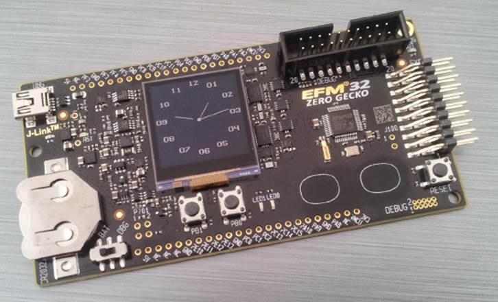
Of course, the board still has input devices; it has two push buttons and two touch-sensitive buttons, and has the same extension header as the STK3800. It has a USB input for debugging, and also a CR2032 battery slot.
In this application, you will again be making a clock. Since the STK3200 has a 128 x 128 Memory LCD, you will be using that to display an analogue clock. It will have an hour hand, a minute hand, and also a second hand. Once again, you will be using the power saving modes available on the Zero Gecko, to keep the application running as long as possible on battery power.
Initialization
Initializing the Zero Gecko is exactly the same as the Wonder Gecko. One single function does the entire low-level initialization.
CHIP_Init();
This function sets up the clocks and some of the low-level drivers, setting up registers to a stable state. Once the initialization state is done, you can move on to configuration.
Configuration
Next, the GPIO must be configured. There are four buttons on the STK3800 — two push buttons, and two touch-sensitive pads. For this application, you will only be using the push buttons. PB1 will be configured to advance time by one minute, PB0 to advance time by one hour. The two buttons are connected to the GPIO, which must be configured. Like the previous clock application, the CPU will spend most of its time sleeping, so the buttons must be configured to create an interrupt.
The documentation states that for the STK3200 board, PB0 is connected to PC8, and PB1 is connected to PC9. Before configuring these inputs, the GPIO clock needs to be configured so that the GPIO can react to inputs. Then, each pin is configured as an input, and configured to issue an interrupt when triggered. Finally, IRQs are enabled.
1 static void GpioSetup(void)
2 {
3 /* Enable GPIO clock */
4 CMU_ClockEnable(cmuClock_GPIO, true);
5
6 /* Configure PC8 as input and enable interrupt */
7 GPIO_PinModeSet(gpioPortC, 8, gpioModeInputPull, 1);
8 GPIO_IntConfig(gpioPortC, 8, false, true, true);
9
10 NVIC_ClearPendingIRQ(GPIO_EVEN_IRQn);
11 NVIC_EnableIRQ(GPIO_EVEN_IRQn);
12
13 /* Configure PC9 as input and enable interrupt */
14 GPIO_PinModeSet(gpioPortC, 9, gpioModeInputPull, 1);
15 GPIO_IntConfig( gpioPortC, 9, false, true, true);
16
17 NVIC_ClearPendingIRQ(GPIO_ODD_IRQn);
18 NVIC_EnableIRQ(GPIO_ODD_IRQn);
19 }
The STK3200 does not have a segment LCD display, but rather a Memory LCD. Configuration is done differently, but once again, software abstraction makes it extremely easy to do. Rather than specifically configuring a device, you initialize the display driver, which correctly configures the device that is present on that microcontroller.
DISPLAY_Init();
From here on, you can use instructions to write geometric shapes and text directly onto the display.
There is one more thing required before you are ready to start. In the previous example, the system spent most of its time in low power mode, using the RTC to wake up the device every minute to refresh the time. This application will be similar, but since this evaluation board has an impressive Memory LCD screen, you will be writing an application that shows analog time, and with a second hand. Therefore, the RTC has to be configured, but this time, instead of waking the system every minute, the RTC will be programmed to wake the system every second. The STK3800 had an intelligent Segment LCD controller that could perform basic animations on its own, but that isn’t possible on a Memory LCD. Instead, every second, the screen will be updated with a graphical second hand.
First things first; programming the RTC. The RTC configuration looks very much like the configuration for the STK3800, the only differences being the interrupt configuration and the divider. Since the RTC is counting a relatively small lapse of time, there is no need for a divider. The code will look like this:
1 void RtcInit(void)
2 {
3 RTC_Init_TypeDef rtcInit = RTC_INIT_DEFAULT;
4 /* Enable LE domain registers */
5 CMU_ClockEnable(cmuClock_CORELE, true);
6 /* Enable LFXO as LFACLK in CMU. This will also start LFXO */
7 CMU_ClockSelectSet(cmuClock_LFA, cmuSelect_LFXO);
8 /* Enable RTC clock */
9 CMU_ClockEnable(cmuClock_RTC, true);
10 /* Initialize RTC */
11 rtcInit.enable = false; /* Do not start RTC after initialization */
12 rtcInit.debugRun = false; /* Halt RTC when debugging. */
13 rtcInit.comp0Top = true; /* Wrap around on COMP0 match. */
14 RTC_Init(&rtcInit);
15 /* Interrupt at specified frequency. */
16 RTC_CompareSet(0, (CMU_ClockFreqGet(cmuClock_RTC) / RTC_FREQUENCY) - 1);
17 /* Enable interrupt */
18 NVIC_EnableIRQ(RTC_IRQn);
19 RTC_IntEnable(RTC_IEN_COMP0);
20 /* Start counter */
21 RTC_Enable(true);
22 }
On line 3, the RTC structure is created, and it is filled in on lines 11 to 13. Finally, the RTC is initialized on line 14, but not enabled (line 11). At line 16, the interrupt is set to every second, and interrupts are enabled on lines 18 and 19. Finally, the RTC is enabled, and the function returns.
Main Application
First, the application will need to know the current time. It will use a structure that only needs to be used inside the main function:
struct tm *time = localtime((time_t const*)&curTime);
A routine will need to be created that sets the graphics background and prints the background image. To save space and time, you could create an entire background image in Flash — a constant table 128 bits by 128 bits. To copy this table to the framebuffer, a simple command is used:
status = GLIB_drawBitmap(&glibContext,
0, 0, BACKGROUND_WIDTH, BACKGROUND_HEIGHT,
(uint8_t*)background);
This routine will start in one corner (0, 0), and finish in the opposite corner (BACKGROUND_WIDTH, BACKGROUND_HEIGHT), and fill in the image with the table found at background. For this example, the background width and height are set to the resolution of the Memory LCD:
#define BACKGROUND_WIDTH (128)
#define BACKGROUND_HEIGHT (128)
The interesting part of Memory LCD screens is that only the pixels that need updating are actually updated. Each pixel has its own one-bit memory, providing an always-on image, and using very little current. Memory LCD screens are fast enough to display animations, and the Cortex-M0+ has fast I/O capability that is more than able to keep up with animations. Therefore, displaying the background before displaying the hands is an acceptable solution. Only the pixels that have changed since the last screen refresh are updated (where the hands used to be), so there is no screen tearing.
Once the background has been transferred to the Memory LCD memory, it is time for a little bit of arithmetic. The “hands” are digital — a graphical line from the center of the screen to the exterior of a circle, depending on the time. This will be done with some trigonometry. You will be calculating the sine and cosine of the current time to produce coordinates for lines. This brings up a question: This processor will be calculating sines and cosines; wouldn’t a Cortex-M4 with an FPU be a better choice? The answer is no. While it is true that a Cortex-M4 with an FPU would have better precision and be faster, the Cortex-M0+ is more than capable. Firstly, even though you will be calculating trigonometry, there is no need for lots of precision. The result of a calculation will be used to display a line, and then immediately be discarded. In the very worst case, a lack of precision means that a hand might be off by one pixel, something that the end user will never notice. The application does not need that much precision. Secondly, what the application requires is a low-powered processor. The Cortex-M4F might be slightly faster for this type of calculation, but the processor will only be calculating a few sines and cosines per second before returning to a low-power mode. The Cortex-M0+ is the best candidate for this situation.
First, the minute hand. The minute hand will be a line, starting from the center of the clock, and it will have a length of 45 pixels. Imagine a circle, the center of which is the middle of the Memory LCD, and with a radius of 45 pixels. The minute hand will be a line from the center to a point on this circle, depending on the amount of minutes. You need to define a few variables before starting.
#define BACKGROUND_WIDTH (128)
#define BACKGROUND_HEIGHT (128)
#define CENTER_X (BACKGROUND_WIDTH/2)
#define CENTER_Y (BACKGROUND_HEIGHT/2)
#define MIN_START 0
#define MIN_END 45
Now, you will need to create a function to calculate the start and end of the line. For the minute hand, the line will start at the center, so this is easy, only the end coordinates will be calculated.
void MinuteHandDraw(int minute)
{
double a = (double)minute / 30.0 * PI;
GLIB_drawLine(&glibContext,
CENTER_X, /* start x */
CENTER_Y, /* start y */
CENTER_X + (int)(MIN_END * sin(a)), /* end x */
CENTER_Y - (int)(MIN_END * cos(a))); /* end y */
}
This function calculates the end coordinates, and then performs the drawing via the function GLIB_drawLine. Now you will do the hour hand. The hour hand will be a little different from the minute hand. The angle will be calculated as a mixture of the hours and the minutes. Hour hands are also shorter, so make this one 30 pixels long.
#define HOUR_START 0
#define HOUR_END 30
Now, create an HourHandDraw function.
void HourHandDraw(int hour, int minute)
{
int position = hour * 5 + minute / 12;
double a = (double)position / 30.0 * PI;
GLIB_drawLine(&glibContext,
CENTER_X, /* start x */
CENTER_Y, /* start y */
CENTER_X + (int)(HOUR_END * sin(a)), /* end x */
CENTER_Y - (int)(HOUR_END * cos(a))); /* end y */
}
The code is almost identical to the previous function, except that a slight adjustment is made for the current amount of minutes. As the minute hand advances towards 12, the hour hand will also slowly advance towards the next hour, just like a real clock.
If you require very low power operation, it is possible to stop here and to program the RTC to create an interrupt every minute. That way the screen will be updated by the microcontroller every minute. However, for this application, the requirement is to have a second hand, and the RTC has already been programmed to interrupt every second.
The second hand is slightly shorter, but also, for aesthetics, it will not start at the center, but slightly off, at a radius of 10 pixels.
#define SEC_START 10
#define SEC_END 35
Since the beginning coordinate will not start at the center of the screen, you must calculate both the start and the finish coordinates.
void SecondHandDraw(int second)
{
double a = (double)second / 30.0 * PI;
GLIB_drawLine(&glibContext,
CENTER_X + (int)(SEC_START * sin(a)), /* start x */
CENTER_Y - (int)(SEC_START * cos(a)), /* start y */
CENTER_X + (int)(SEC_END * sin(a)), /* end x */
CENTER_Y - (int)(SEC_END * cos(a))); /* end y */
}
You can now display the background image and the three hands of the clock. All that remains to be done is to create a main loop.
void main(void)
{
while(1)
{
time = localtime((time_t const*)&curTime);
GLIB_drawBitmap(&glibContext,
0, 0, BACKGROUND_WIDTH, BACKGROUND_HEIGHT,
(uint8_t*)background);
HourHandDraw(time->tm_hour % 12, t->tm_min);
MinuteHandDraw(time->tm_min);
SecondHandDraw(time->tm_sec);
/* Enter low-power mode */
EMU_EnterEM2(false);
}
}
The main loop simply gets the current time before updating the background image and displaying the three hands. Finally, the microcontroller is put into low-power mode, stopping program execution but retaining RAM. The microcontroller will stay in that state until it receives an interrupt, continuing program execution.
What Now?
Silicon Labs provides a more complete version of this application with their evaluation kit. It only briefly shows some of the functions, but the complete version has support, not only for an analog clock, but also a digital interface and functions for setting the time.
Using the same principle, it would be interesting to create a stopwatch and some other functions found commonly on wristwatches; showing the current date, for example. Once again, the STK3200 has excellent I/O capacity, and this card can be programmed to activate GPIOs depending on the time, for example a buzzer, useful for an alarm clock function.
Atmel D20 Xplained Pro
Atmel was founded in 1984, and ever since then, it has been close to hobbyists and makers, while also being a world-class supplier of next-gen logic circuits.
In 1995, Atmel did something unique; it developed a processor with integrated flash memory: a Flash Micro. It was based on the Intel 8051 and was a huge success with the simplified programming mechanism; the processor itself was programmed and no longer required external ROM.
In 1996, Atmel developed the AVR, an 8-bit RISC microcontroller that was also a Flash Micro. All other microcontrollers at the time used PROM or EEPROM, making modifications difficult, sometimes even impossible. Although the integrated flash memory was comparable to Atmel’s version of the Intel 8051, the design itself was radically different. The AVR was designed to be used with high-level programming languages such as C and was an efficient RISC core.
The AVR line was an instant hit and was loved by electronics enthusiasts everywhere. Some amazing projects have been created, but they were still 8-bit microcontrollers. Recently, Atmel developed AVR microcontrollers based on 32-bit cores, but also created a new line of products, using an ARM Cortex-M core, delivering a unique combination of power efficiency, flexibility, and performance. However, Atmel hasn’t simply taken an ARM core and put its logo on it; the Peripheral Event System is something that was loved by AVR enthusiasts and enables peripherals to interact with each other without using CPU resources. This technology is still available in Atmel’s AVR line, in both Atmel’s 8- and 32-bit versions, and Atmel has also created something very similar for their ARM-powered line of devices.
Atmel’s D20 microcontroller line is based on a Cortex-M0+ core and comes with an evaluation board, the SAM D20 Xplained Pro (see Figure 5-5). Although other boards may have different sensors or LCD screens, the D20 Xplained Pro has one user button and one LED. It doesn’t have an LCD screen, and it doesn’t have a light sensor, but what it does have is three extension headers; all three are the same electronically.
FIGURE 5-5: Atmel’s SAM D20 Evaluation Board
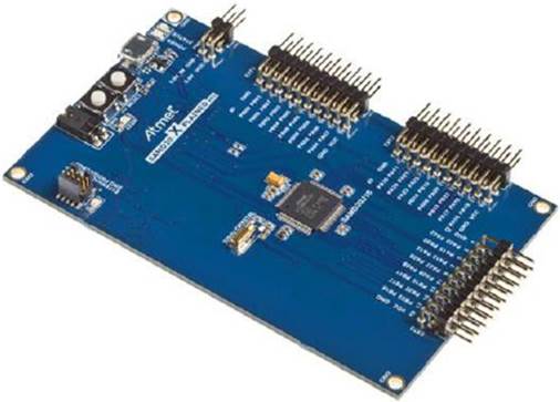
The Xplained Pro series isn’t just based on the SAM D20; other processors use the same interfaces. Atmel therefore also created an interesting line of external peripherals, or “wings” as they are sometimes called. The I/O1 board provides a light sensor, temperature sensor, and micro-SD reader. The OLED1 board provides a 128 x 32 OLED display, as well as three buttons and three LEDs. The QT1 board contains touch sensors used with Atmel’s Peripheral Touch Controller. If none of these boards contains what you need, the PROTO1 board provides a bread-boarding area where you can use your own components. All of these boards use a common connector — the Xplained Pro header.
Atmel Studio integrates Atmel Software Framework (ASF), a large library with thousands of project examples and code extracts.
All of these boards are supported by Atmel’s SDK, and ASF provides primitives and examples for each of the different components. You won’t spend any time developing your own drivers for these devices; Atmel Studio allows you to import the modules you require directly into your application.
Test Application
The SAM D20 Xplained Pro board does not have some of the peripherals found on other boards, like a segment LCD, for example. That does not stop it from being able to test simple applications. It does have a user LED, and a user button. Using these two devices, it is very easy to create a test application. In just a few lines of code, it is possible to create an application that turns the LED on if the button is pressed, or turns it off otherwise. The application will look like this:
int main(void)
{
system_init();
while(1)
{
if (port_pin_get_input_level(BUTTON_0_PIN) == BUTTON_0_ACTIVE)
{
port_pin_set_output_level(LED_0_PIN, LED_0_ACTIVE)
}
else
{
port_pin_set_output_level(LED_0_PIN, !LED_0_ACTIVE)
}
}
}
The function system_init() quickly sets up the board. Then the application loops, and scans the state of the user button, BUTTON_0. If BUTTON_0 is active, the LED output is set to high; otherwise, it is set to low. This is the default program that is generated when creating a new project, and is an excellent way to test that the board is functioning.
With the click of a button, Atmel Studio compiles the project. All project dependencies are compiled, and a binary is generated. Another click later, and the binary is flashed onto the Xplained Pro board. The SAM D20 comes with a hardware debugger built directly onto the board, and Atmel Studio makes the most of this to automatically flash an application and to perform debug operations.
Weather Station
As stated previously, Atmel also makes a large set of extension boards, notably the I/O1 board and the OLED1 board. The I/O1 board has a temperature sensor, and the OLED1 board has a 128 x 32 OLED display. With these two boards, it is possible to create a digital thermometer, reading the temperature from one board and displaying it on the other. The temperature will be precise to one tenth of a degree.
Atmel provides a training document for the SAM D20 series, to get to know the processor as well as Atmel’s development environment — Atmel Studio. This document shows how to set up Atmel Studio 6, which is beyond the scope of this book. In this section, I will concentrate on the code, not Atmel Studio. Atmel has excellent documentation that comes with Xplained Pro boards; please consult that documentation for information on how to use their interface.
Initialization
The SAM D20 requires some initialization before being able to run an application. This includes setting up the system clocks and some hardware configuration, but thanks to Atmel’s SDK, this is a simple task. When creating a blank project, several files are generated. One of them, conf_clocks.h, contains default clock settings, and can be used without any modification. As seen in the previous example, a single line of code is sufficient:
system_init();
This function takes the information in conf_clocks.h and performs low-level system initialization. Once this is done, you are now ready to perform configuration.
Configuring the Temperature Sensor
Atmel produces a wing that is perfect for this application, the I/O1. The I/O1 is a relatively small circuit board, but packed with peripherals. It contains a light sensor, temperature sensor, an SD card reader, and even a free GPIO connector. The I/O1 board is shown in Figure 5-6.
FIGURE 5-6: Atmel’s I/O1 Wing
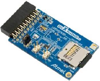
The temperature sensor on the I/O1 wing is an Atmel AT30TSE758, a lightweight component which is interfaced with I2C. Atmel provides a driver for this component, and including the driver is as simple as importing an ASF driver from Atmel Studio. This imports a new file,conf_at30tse75x.h, containing the driver configuration options. Most of Atmel’s drivers exist in two formats: polled, or callback. For this application, all operations will be polled.
Once the driver has been imported, all of the necessary calls are added to the project. Initializing the temperature sensor is as easy as calling a single function:
at30tse_init();
For this application, a sensor resolution of 12 bits will be used. This can be set with another function, at30tse_write_config_register. To keep all the configuration routines together, a new routine will be created:
static void temp_sensor_setup(void)
{
/* Init and enable temperature sensor */
at30tse_init();
/* Set 12-bit resolution */
at30tse_write_config_register(
AT30TSE_CONFIG_RES(AT30TSE_CONFIG_RES_12_bit));
}
Reading from the temperature sensor is once again a simple command; at30tse_read_temperature returns a double, containing temperature information. However, before reading the temperature, you must configure the output device on which the temperature will be written.
Configuring the OLED Display
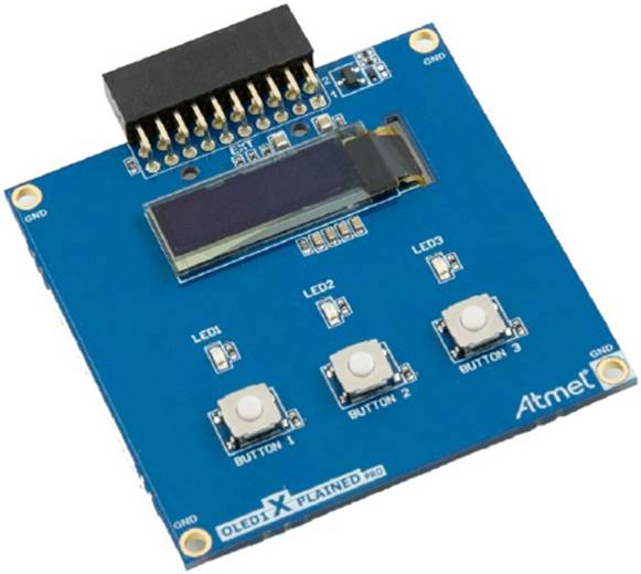
Atmel’s OLED1 wing contains a bright 128 x 32 OLED display, three buttons and three LEDs, and also connects to an Xplained Pro extension header. It is illustrated in Figure 5-7. This is an excellent way of viewing the current temperature.
FIGURE 5-7: Atmel’s OLED1 Wing
Once again, adding the OLED display to your project is as simple as importing a driver. An entire library has been created, not only to access the display, but also graphical functions for writing text and for graphical primitives. In order to import the driver, you must add the “GFX Monochrome - System Font” service. This not only imports the display driver, but also the communication method (SPI), graphical primitives, and the framebuffer device. Adding this ASF adds two header files:
conf_ssd1306.h and conf_sysfont.h.
Once again, a C function is required to initiate the graphics device. This is done in a single statement:
gfx_mono_init();
Putting It All Together
The two components used on this project have been imported, and one configuration routine has been created, for the temperature sensor. The graphics device only requires one line, so there is no need to create a function.
What is needed now is to add the device configuration. Add the configuration to the main function. Also, add a variable to hold the temperature value. The main function will look like this:
int main(void)
{
double temp_result;
/* Low-level initialization */
system_init();
/* Setup the graphics */
gfx_mono_init();
/* Setup the temperature sensor */
temp_sensor_setup();
/* Get a first reading */
temp_result = at30tse_read_temperature();
}
The application is beginning to take shape, but it doesn’t yet tell the user what the temperature is. Luckily, the OLED can be used as a terminal device; printing text is as simple as snprintf.
There are three things that must be declared before continuing. First, the maximum size of a string to be printed out — 20 should be more than enough.
#define APP_STRING_LENGTH 20
Secondly, the application must know where to print the text, in XY coordinates.
#define APP_POSITION_X 0
#define APP_POSITION_Y 0
Now, add a variable to hold the text.
char temp_string[APP_STRING_LENGTH];
This application needs to convert the temperature data into a string that can be displayed, and to do that the standard library must be imported.
#include <stdio.h>
Now, time to display the temperature. The temperature is held in the variable temp_result, which has been defined as a double. The standard library does not support many floating-point conversions due to size constraints, and especially the %f formatting specifier is not included. Therefore a bit of calculation is required.
For the decimal number, casting temp_result to int will discard the fractional part.
For the fractional part, the first digit after the decimal point will be used. To obtain this, temp_result will be multiplied by 10, before casting to an int to remove the remaining fraction. Finally, taking the modulo 10 will obtain the digit in the ones’ place.
This can be expressed by the following instructions:
snprintf(temp_string,
APP_STRING_LENGTH,
"Temp: %d.%dC\n",
(int)temp_result",
((int)(temp_result * 10)) % 10);
gfx_mono_draw_string(temp_string,
APP_POSITION_X, APP_POSITION_Y, &sysfont);
Now all that remains to be done is to add a loop, continuously read the temperature, and print the result. The final application will look like this:
#include <stdio.h>
#define APP_POSITION_X 0
#define APP_POSITION_Y 0
#define APP_STRING_LENGTH 20
int main(void)
{
double temp_result;
char temp_string[APP_STRING_LENGTH];
/* Low-level initialization */
system_init();
/* Setup the graphics */
gfx_mono_init();
/* Setup the temperature sensor */
temp_sensor_setup();
/* Keep looping */
while (true)
{
/* Get a first reading */
temp_result = at30tse_read_temperature();
/* Print the temperature */
snprintf(temp_string,
APP_STRING_LENGTH,
"Temp: %d.%dC\n",
(int)temp_result",
((int)(temp_result * 10)) % 10);
gfx_mono_draw_string(temp_string,
APP_POSITION_X, APP_POSITION_Y, &sysfont);
}
}
What Now?
With only a few lines of code, and without having knowledge of the electronic components on the wings, you have created a fully functional application. It is, of course, possible to add to this application. On the same wing as the temperature sensor is a light sensor and also an SD card reader. It is possible to create an application that not only records the temperature, but also the light levels, and to store them on an SD card. An entire Xplained Pro header is still available, so it is perfectly possible to add even more components; you could place a barometer or possibly a tachometer for measuring wind speed. With a small battery (Atmel also provides a battery case, the ATBATTERY-CASE-4AAA), this weather station could sit in a garden for weeks and record the weather for statistical data. You could even add a low-power Bluetooth device to automatically upload data when you connect, so you don’t have to take out the SD card. With the SAM D20 Xplained Pro board and accessories, anything is possible.
CASE STUDY: U-BOOT
When a computer is turned on, most people think that the first program to run is the operating system. When turning on a computer, you are greeted by a Windows logo, a MacOS background, or a Linux penguin. Most people tend to be unaware of the BIOS, which is actually a program in itself. Linux users who dual boot often see another application: either LILO or GRUB during the boot process. These two applications are known as boot loaders; their job is to provide the processor with a kernel to load. When they have loaded a kernel into RAM, they give full control to the kernel and are subsequently deleted from memory.
U-Boot from Denx Software is a well-known bootloader for embedded systems. Not only is it used extensively on development boards for its ease of use, it is also open source and can therefore be used to study bootloader operation and low-level programming.
U-Boot doesn’t just load a kernel into memory, it does far more. It can open a serial port and accept commands. It can use serial protocols to upload new binaries; it can output board and flash information; and it can also load kernels from specific locations, including from an Ethernet adapter. U-Boot has an impressive list of commands, which can be augmented with some development.
Inside the examples folder are a few programs that show you the power of this application. For example, the hello_world.c program can be compiled and copied to the target system using serial:
=> loads
## Ready for S-Record download ...
~>examples/hello_world.srec
1 2 3 4 5 6 7 8 9 10 11 ...
[file transfer complete]
[connected]
## Start Addr = 0x00040004
=> go 40004 Hello World! This is a test.
## Starting application at 0x00040004 ...
Hello World
argc = 7
argv[0] = "40004"
argv[1] = "Hello"
argv[2] = "World!"
argv[3] = "This"
argv[4] = "is"
argv[5] = "a"
argv[6] = "test."
argv[7] = ""
Hit any key to exit ...
## Application terminated, rc = 0x0
U-Boot can be used on almost any system because it supports most processor families, including ARM processors. It natively supports some filesystems, including common filesystems such as FAT and EXT2, as well as embedded filesystems such as JFFS2.
It is common to see development boards running U-Boot for flexibility and to have a suite of test applications written for U-Boot. With this bootloader, engineers can simulate events that are hard to reproduce; a program might corrupt specific areas of NAND flash to see how a backup partition reacts, or hardware might be set to a specific state before system boot. Some applications are also geared toward performance, running benchmarking applications independently of hardware to know the true throughput of a device bus, for example, and then comparing it to what is achieved running an operating system.
MACHINE STUDY: RASPBERRY PI
In 1981, Acorn released the BBC Micro, a computer system designed to be used in schools. Acorn designed a processor that was spun out into ARM, and in 2012, those processors were again back in schools with the Raspberry Pi, a credit-card sized single-board computer designed by the Raspberry Pi Foundation based on an ARM core: an ARM1176JZF-S.
The original intention of the Raspberry Pi Foundation was to create a computer for schools, perfect for teaching computer literacy. The low-cost design makes it easy to buy one computer per child, and with no internal hard drive, it is rugged and is not easy to break. Also of interest, because all the firmware resides on the SD card, it is almost impossible to get a Raspberry Pi into a state in which it cannot boot. There is no BIOS to flash, and there is no way of corrupting the bootloader image. This makes it perfect for learning ARM programming.
The Raspberry Pi boots from an SD card, so switching operating systems is as simple as swapping SD cards. Several operating systems are available: Debian and Arch Linux distributions are available, and a Fedora remix is also available. Also of interest is RISC OS, an operating system originally designed by Acorn and bundled with all Acorn Archimedes machines.
Although the Raspberry Pi was originally designed for schools, it has made a huge impact on the Maker community, a community of electronics and programming enthusiasts that dream of new contraptions, or simply identify a need and create a solution, and multiple projects have been created for this small-factor computer. It has been used for robotics systems, home automation, security, and just about anywhere that a user has identified a need. It is an excellent tool to learn about ARM systems, and a great way of having fun. When you have finished writing ARM binaries, you can swap the SD card and relax while playing a special version of Minecraft for the Raspberry Pi, or watching your favorite film directly on your television through some excellent video programs.
The Raspberry Pi is an entire computer system; it has video capabilities, USB, Ethernet, and enough system resources to run a full Linux system, so why is this considered to be embedded? Well, that all depends on your definition of embedded. It is a small factor computer, with everything on-board, and compared to a desktop computer, it has limited resources. What is interesting about this system is its versatility; by studying the boot procedure, it is possible to have a full Linux system, or to create a bare metal application, without all the fuss of flashing via specialized tools. The Raspberry Pi is an excellent low-cost starter platform.
Boot Procedure
The Raspberry Pi has an interesting boot procedure. On power on, the ARM core is held in a reset state, while the GPU takes control of the system. The GPU has some internal firmware that is responsible for the first boot steps, including reading from the first partition of the SD card. For the Raspberry Pi to boot, the first partition must be formatted to FAT32 and must contain several files.
bootcode.bin
This is the first file to be loaded from the SD card by the GPU. It is loaded into the L2 cache, and its role is to enable the SDRAM memory and to configure a few system settings. It then loads the next bootloader stage.
loader.bin
This file contains the binary routines necessary to load and execute ELF binaries, and looks for start.elf on the SD card.
start.elf
This is the final bootloader stage and where the magic starts. This file can load a file called kernel.img and place it at memory location 0x8000 (from the ARM core’s point of view). The start.elf file can also use an external file called config.txt that contains different parameters to fine-tune the ARM core (overclocking and overvoltage, for example). After kernel.img has been loaded into system memory, start.elf releases the reset state on the ARM core and gives it control.
kernel.img
This file is an ARM executable file, more often than not a Linux kernel. This can also be a bare metal application that you can design.
Compiling Programs for the Raspberry Pi
The interesting thing about the Raspberry Pi is that it comes with a complete Linux distribution and is fast enough to have its own compiler to compile binaries for itself. If you have another computer next to it, it is also possible to test out a cross-compiler environment, for both Linux binaries or for barebones applications because the Raspberry Pi can do both.
As seen previously, the GCC compiler needs to know a little bit more about the target processor before compiling. The Raspberry Pi uses an ARM1176JSF-S, which is an ARMv6 core, and has an FPU. So, the GCC command-line options should look like this:
-Ofast -mfpu=vfp -mfloat-abi=hard -march=armv6zk -mtune=arm1176jzf-s
In all the previous examples, you had to configure the vector table, but because start.elf places the binary at 0x8000, you don’t have to do that. Of course, if you need interrupts or if you want to handle exceptions, then you will have to configure that, but for basic barebones applications, you can ignore that.
Now try a simple program.
void main(void)
{
while(1)
{
}
}
Save this as kernel.c. This program doesn’t do anything, but it serves to show how the compilation works. So now compile that application.
arm-none-eabi-gcc -O2 -mfpu=vfp -mfloat-abi=hard -march=armv6zk \
-mtune=arm1176jzf-s -nostartfiles kernel.c -o kernel.elf
The -nostartfiles option tells the compiler to avoid all the code used to start programs in an operating system environment; it especially avoids adding exit() functions, something that you do not need here. The binary is compiled as an ELF, so it needs to be transformed into a binary before you proceed.
arm-none-eabi-objcopy kernel.elf -O binary kernel.img
You can output this program to the filename kernel.img because that is what is expected on the SD card. Now that everything is compiled, you can copy kernel.img to your SD card along with the other files (provided by the Raspberry Pi Foundation, available on its website), and you are good to go. More information can be found at http://www.raspberrypi.org/downloads.
What’s Next?
This simple program does nothing except put the processor into an infinite loop, but the Raspberry Pi also has other output devices. There is a serial port for writing a possible “Hello, World!” line. It has a GPIO header, and expansion boards are available, so you can create electronic projects to automate your home (example projects of a door lock are available), but there is also an HDMI output if you want to create graphic output and maybe even animation.
SUMMARY
This chapter gives a few example programs and techniques on both emulated and real-world boards. They have been in a mixture of assembly and C, some require specific hardware initialization, and some are close to systems programming. Now that you have followed these examples, you have two desktop clocks and a weather station, all made using readily available boards and programming tools.
The next chapter will present the Thumb extension, a versatile language created for high-density applications and microcontroller profiles. You will see the different instructions, and how to generate efficient Thumb code.
All materials on the site are licensed Creative Commons Attribution-Sharealike 3.0 Unported CC BY-SA 3.0 & GNU Free Documentation License (GFDL)
If you are the copyright holder of any material contained on our site and intend to remove it, please contact our site administrator for approval.
© 2016-2026 All site design rights belong to S.Y.A.