Make: AVR Programming (2014)
Part II. Intermediate AVR
Chapter 9. Introduction to the Timer/Counter Hardware
AM Radio Transmitter and Reaction Timer
In this chapter, we’ll test our reaction time, refine our old organ routines, and transmit AM radio directly from the AVR. What do these projects have in common? They’re all made possible by the internal timer-counter hardware. Previously, we’ve marked the passing of time by holding up the CPU in counting delay loops. No more! The AVRs have dedicated hardware that’ll do that for us.
In all of these cases, you’ll find that using the hardware timers costs a little bit in initial setup, but makes your resulting code significantly simpler, makes the timing significantly more accurate, and frees up the CPU for useful work.
WHAT YOU NEED
In addition to the basic kit, you will need:
§ A speaker and DC-blocking capacitor.
§ A pushbutton to test your reaction time.
§ A long length of wire for an AM antenna.
§ A USB-Serial adapter to display your times.
Timer/Counters: Why and How?
Looking back at the serial-port organ code, the function that made the music (such as it was) was called playNote(). It worked by turning the speaker pin on and waiting, and then turning the speaker pin off and waiting. To refresh your memory, see Example 9-1.
Example 9-1. Old playNote() listing
void playNote(uint16_t wavelength, uint16_t duration) {
uint16_t elapsed;
uint16_t i;
for (elapsed = 0; elapsed < duration; elapsed += wavelength) {
/* For loop with variable delay selects the pitch */
for (i = 0; i < wavelength; i++) {
_delay_us(1);
}
SPEAKER_PORT ^= (1 << SPEAKER);
}
}
This code works just fine, but if you’d like the CPU to do anything else at the same time, you’re out of luck—it’s all tied up doing the important task of waiting for a precise amount of time. We run into a similar situation with our LED blinking code where we invoke the_delay_ms() function. All of our processor power is momentarily tied up just spinning around in a fruitless loop that simply counts up until it’s done.
What we need instead is a clock that we can use as a timebase and a counter that’ll count up a certain number of clock ticks for us before it acts. This is, of course, what the internal timer/counter hardware peripheral does. Before we get down to applications, let’s take a quick tour of the hardware to see how it works. It’ll give you a better feel for the possibilities.
Essentially, the timer/counter hardware works as summarized in Figure 9-1. Input arrives from either the system clock or an external source connected up to an input pin (T0 for counter 0). In this way, the same hardware can be used as a timer (counting ticks of the system clock) or a generic counter (counting voltage change events on the dedicated input pin). The current count is stored in an internal timer/counter register (TCNTn).
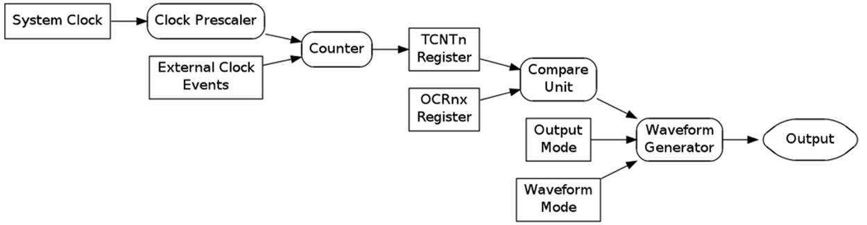
Figure 9-1. Timer/counter hardware
Your code can read the count from TCNT registers at any time, yielding the current count value. You can also write to it, and you’ll often do so in order to reset the count to zero. With just reading and writing to the timer register, you can make the equivalent of a stopwatch—set the timer value to zero, do something, and then check the value again to see how much time has elapsed.
If instead of a stopwatch, you’d like an alarm clock, you can put the Timer Compare Unit to work for you. Its job is to let you know when a certain count value is reached. You store this compare value in the Output Compare Register (OCRn). This way, you can store the value you’d like for an elapsed time, a frequency or a duty cycle in the OCRn, and then forget about it—the timer hardware will do the rest for you, freeing up the CPU to do more interesting things.
So the counter is counting, and the compare unit is comparing the count value to a value that you set. What happens when the compare value is reached? A compare event triggers the Waveform Generator, and what it does depends on a pair of important configuration options: the waveform mode and output mode. In brief, the Waveform Generator unit can be configured to generate three main types of output depending on the waveform mode: counter, timer, or (in Chapter 10) PWM. Whether you want pins set, cleared, or toggled is determined by the output modes. The timer/counters can also trigger interrupts, which is useful when you want to periodically update variables or run code; you’ve seen a bunch of interrupt examples in Chapter 8. In this chapter, we’ll be focusing on counter and timer waveform modes, and direct-to-pin output.
And if one timer/counter weren’t enough, the ATmega series of AVR chips have three timers, two with 8-bit (256 step) resolution and one with 16-bit (65,356 step) resolution. That way, you can have one timer/counter generating a frequency for you, another keeping track of wall-clock time, and the third timing short-duration events. They’re very useful once you’ve learned how to use them.
As you can see, there’s a lot of flexibility and utility built into the timer/counter hardware. If you want to count button presses, you can simply hook up your (hardware-debounced) switch directly to the appropriate counter input pin. Or imagine that you want to get the time in between button presses. Then you can set your code to zero the TCNT register at the beginning, connect the counter up to the system clock, and then when the button is pressed, simply read out the value in TCNT. The count will be the number of system clock ticks that have elapsed, which you can then manipulate any way you want. And because all of this is taken care of by the timer/counter hardware, the CPU is free to listen to serial ports or crunch numbers at the same time.
BASIC WAVEFORM GENERATION MODES
When you’re configuring the timer/counter hardware, the first thing you’ll need to decide is what mode of operation you want the timer/counter operating in. The AVR datasheet includes fairly good descriptions of each of these modes, and also a table that describes the bits you need to set to put the timers in each mode. Because we’ll be covering the PWM modes in Chapter 10, here’s a summary of the two basic timer/counter modes:
Normal Mode
In this mode, the counter counts up until it overflows at 255 or 65,535. You use this mode most when you’re counting clicks, timing an event, or clearing and reading TCNT from your code. We’ll be using Normal Mode for the reaction timer.
CTC Mode
In Clear Timer on Compare Match mode, the counter resets itself automatically when it reaches the value that’s stored in the OCRnA register instead of waiting until it hits 255 or 65,535. So by writing to the output compare register, we control the frequency of the cycles. Configuring a pin to toggle, set, or clear when a match occurs is a very common choice. Use this mode when you want an adjustable frequency or timebase. We’ll be using CTC mode for audio frequency generation in the revised organ code and for the (somewhat tuneable) carrier frequency of our AM transmitter. By triggering an interrupt when the counter resets, we can also execute arbitrary ISR code in a strictly timed fashion. This more advanced use of timers with interrupts will be the basis of a real-time clock and all sorts of scheduling systems.
Test Your Reaction Time
I’ve used milliseconds or microseconds to describe lengths of time quite a lot, but do you really know how long a millisecond is? Or 100 milliseconds? To the CPU, a millisecond is an eternity—at 8 MHz, it can run eight thousand computations in that time—but for humans, 100 milliseconds is fast. When we were debouncing switches, I mentioned that human reaction time was on the order of tens to hundreds of milliseconds. Here’s your chance to test it out.
Flash in the reactionTimer.c code here, and then open up a serial terminal window at 9,600 baud to communicate with the AVR. The program will wait for any key from your computer keyboard, then wait a slightly random delay time between 1 and 3.5 seconds, and then light all the LEDs. When that happens, your job is to press the button attached to pin PD2 as quickly as you can. Your time, in seconds, is sent over the USART for display. Have a quick skim through the code in Example 9-2 and see if you can figure it out.
Example 9-2. reactionTimer.c listing
/*
Press the button as quickly as you can after the LEDs light up.
Your time is printed out over the serial port.
*/
// ------- Preamble -------- //
#include <avr/io.h>
#include <util/delay.h>
#include <avr/interrupt.h>
#include "pinDefines.h"
#include "USART.h"
#include "support.h"
static inline void initTimer1(void) {
/* Normal mode (default), just counting */
TCCR1B |= (1 << CS11) | (1 << CS10);
/* Clock speed: 1 MHz / 64,
each tick is 64 microseconds ~= 15.6 per ms */
/* No special output modes */
}
int main(void) {
char byte;
uint16_t timerValue;
// -------- Inits --------- //
initUSART();
initTimer1();
LED_DDR = 0xff; /* all LEDs for output */
BUTTON_PORT |= (1 << BUTTON); /* enable internal pull-up */
printString("\r\nReaction Timer:\r\n");
printString("---------------\r\n");
printString("Press any key to start.\r\n");
// ------ Event loop ------ //
while (1) {
byte = receiveByte(); /* press any key */
printString("\r\nGet ready...");
randomDelay();
printString("\r\nGo!\r\n");
LED_PORT = 0xff; /* light LEDs */
TCNT1 = 0; /* reset counter */
if (bit_is_clear(BUTTON_PIN, BUTTON)) {
/* Button pressed _exactly_ as LEDs light up. Suspicious. */
printString("You're only cheating yourself.\r\n");
}
else {
// Wait until button pressed, save timer value.
loop_until_bit_is_clear(BUTTON_PIN, BUTTON);
timerValue = TCNT1 >> 4;
/* each tick is approx 1/16 milliseconds, so we bit-shift divide */
printMilliseconds(timerValue);
printComments(timerValue);
}
// Clear LEDs and start again.
LED_PORT = 0x00;
printString("Press any key to try again.\r\n");
} /* End event loop */
return (0); /* This line is never reached */
}
I’ve shifted the pretty-printing functions off to another pair of support.c and support.h files. If you look at the makefile, you’ll see that it includes them in addition to the USART files. All of this is to keep the main reactionTimer.c code tight and keep you focused on the timers. So for now, just assume that randomDelay(), printMilliseconds(), and printComments() do what their names imply.
The initialization section is pretty standard for our applications, and we’ll get to initTimer1() soon, so skip on down to the event loop, which starts off by waiting for a byte (any byte) across the USART. After a random delay, all the LEDs light up, “Go!” is transmitted on the USART, and we have the first timer-specific bit of code.
As described in the timer/counter overview, the current timer count value is kept in a hardware register called TCNT1 for Timer 1. (Not surprisingly, the counter register for Timer 0 is called TCNT0, and TCNT2 for Timer 2.) In this example, we’re using the timer/counter to simply count up at a fixed rate, starting out from zero. Later, when we read the TCNT1 register, we’ll know how many timer ticks have elapsed. And because people can have widely varying reaction times, I’ve chosen to use the 16-bit Timer 1 to allow us to easily count values from one eighth of a millisecond up to just over eight seconds.
So after the random delay, the LEDs are turned on, and the counter hardware register is reset to zero. The next thing the code does is checks if you’re already pressing the button and issues an admonishment. (Not that I don’t trust you or anything, but you know how the temptation is…) If you weren’t found to be cheating, the code continues on.
Next, the code goes into an endless loop until you press the button by using the loop_until_bit_is_clear macro function. But wait, if the CPU is looping around waiting, who’s doing the timing in the meantime? That’s right, the timer/counter module. When the button is finally pressed (after an eternity in CPU time), all that’s left to do is read the TCNT1 value out of the register and convert it to (approximate) milliseconds, print it out, and rate your time.
How do we know how long a timer tick lasts? That’s a function of the CPU clock speed and CPU prescaler, so let’s have a look at the initialization routine. In fact, when you get there, you’ll see that all the init routine does is set the clock speed. Looking at Table 15-5 in the “Register Description” section for Timer 1 in the datasheet, you’ll see the list of possible clock speeds and the necessary bits to set to get each of them. Some prescaler modes can be set with just one bit, while others require two or three, like “CPU/64,” which we use here.
ALTERNATIVE REPRESENTATIONS FOR SETTING BITS
You do remember your bit-shifting logic from Chapter 4, right? You’ll frequently need it when reading other people’s code, and may want to use it in your own sometimes.
For instance, the initialization code for setting the timer’s clock-speed prescaler that we wrote as:
TCCR1B |= (1 << CS10) | (1 << CS11);
could be written, using the built-in _BV() macros, as:
TCCR1B |= _BV(CS10) | _BV(CS11);
or using a set_bit style macro as:
#define set_bit(register, bit) \
(register |= (1<<bit))
set_bit(TCCR1B, CS10);
set_bit(TCCR1B, CS12);
or (yuck!) as:
TCCR1B |= 5;
if they’re total jerks.
There’s no reason to ever write nonreadable code like that last example. To figure out if “5” is setting the waveform generation bits or the clock speed, you’ll have to open up the datasheet and do a decimal-to-binary conversion. And all the one-liners compile to the same machine code anyway, so there’s nothing at all gained by using the difficult-to-read notation.
The two-line, set_bit macro version ends up taking twice as many instructions in machine code as TCCR1B |= (1 << CS10) | (1 << CS12);, and after you’re used to the explicit bit shifts, they’re just about as readable. If you’re writing timing-sensitive code, or setting multiple bits in a single register over and over again, the one-liner versions are better.
How did I figure out these timings? I typed make disasm and then read the resulting .lst file to see how the code converts into the machine language that gets flashed into the chip. You can disassemble the machine code by hand with the avr-objdump command. Looking over the quasi-assembler can help demystify compilation process and is informative even if you don’t know a word of assembler yet.
The rest of the reaction timer code is just pretty-printing the results to the serial output and the nice trick used to make a “random” delay. (Using the least significant bits of a fast-updating counter isn’t random by any means, but it’s good enough to make an unpredictable delay, as long as the counter value depends on human input.) These miscellaneous functions are listed in support.h and support.c, and should be fairly readable.
So let’s quickly recap the timer-relevant details of this project before we move on to something more complex. First, once the timer/counter is initialized, it just runs on its own, counting up until it reaches its maximum value and starts again from zero. In this example, I wanted more than 255 possible values for the reaction times, so I used the 16-bit Timer 1, which can count up to 65,535 before rolling over. The speed at which the timer/counter counts depends on the system CPU speed and the CPU prescaler that we pick when we’re initializing the timer. In this case, using an 1 MHz CPU clock and a divide-by-64 prescaler value, each timer tick takes 64 microseconds, which is close enough to 1/16th of a millisecond that we can calculate the timing with a bit-shift divide for convenience.
The initialization of the timer/counter was particularly simple here because we were already using Normal Mode, which is the default, so we didn’t need to set any of the waveform generation mode bits. Additionally, we weren’t using the output of the timer in any way except to read it straight out of the count hardware register, so we didn’t need to set up any of the output-mode bits. All we had to do was set up the clock source/prescaler and off it went.
The rest of this chapter introduces more nuanced ways to use the timer/counter hardware, with just-slightly more complicated initialization routines. Banzai!
Using Timer 0 for a Better 8-Bit Organ
Before we get on to something complicated and slightly hackish like making an AVR into an AM radio transmitter, let’s refine our playNote() code from the serialOrgan project by using the timer/counter in CTC mode. Remember in Basic Waveform Generation Modes, I mentioned that CTC mode is most often used when we want to set the timer/counter to repeat at a given frequency? Well, it turns out that’s exactly what we need to set the pitches on our 8-bit Organ.
To get zero-CPU-use audio out of the AVR, we’re going to use one of the timer/counter’s output modes to toggle our speaker out pin for us each time it goes around a cycle, and then we’ll use the CTC mode’s adjustable compare value to vary the pitch. We want all of this to run within the audio range, so we’ll need to divide down the 1 MHz CPU clock frequency into something more manageable. We’ll use Timer 0 here for simplicity and variety, but there’s no reason we couldn’t use Timer 1 if we wanted higher pitch accuracy or a wider frequency range.
Flash in timerAudio into your AVR and let’s dissect the code listing in Example 9-3. As usual, the initialization section calls initialization functions and then the event loop calls our playNote() function and waits. playNote() is fairly straightforward as well. The speaker output is enabled in its data-direction register, and then the values that correspond to our musical pitches are loaded into the output compare register.
Example 9-3. timerAudio.c listing
/*
Quick audio demo using Timer 0 to generate audio frequencies directly.
*/
// ------- Preamble -------- //
#include <avr/io.h> /* Defines pins, ports, etc */
#include <util/delay.h> /* Functions to waste time */
#include "pinDefines.h"
#include "scale8.h" /* 8-bit scale */
static inline void initTimer(void) {
TCCR0A |= (1 << WGM01); /* CTC mode */
TCCR0A |= (1 << COM0A0); /* Toggles pin each cycle through */
TCCR0B |= (1 << CS00) | (1 << CS01); /* CPU clock / 64 */
}
static inline void playNote(uint8_t wavelength, uint16_t duration) {
OCR0A = wavelength; /* set pitch */
SPEAKER_DDR |= (1 << SPEAKER); /* enable output on speaker */
while (duration) { /* Variable delay */
_delay_ms(1);
duration--;
}
SPEAKER_DDR &= ~(1 << SPEAKER); /* turn speaker off */
}
int main(void) {
// -------- Inits --------- //
initTimer();
// ------ Event loop ------ //
while (1) {
/* Play some notes */
playNote(C2, 200);
playNote(E2, 200);
playNote(G2, 200);
playNote(C3, 400);
_delay_ms(1000);
_delay_ms(1000);
_delay_ms(1000);
} /* End event loop */
return (0); /* This line is never reached */
}
For making a sound, that’s all there is to it—the timer unit takes care of the timing and pin toggling for us. The rest of the function just waits for the specified duration, while the speaker is being driven by the timer, and then turns the speaker off by disabling output on the SPEAKER pin.
Notice what’s different here. In Chapter 5, when we wanted to make sound, we toggled the speaker output bit on and off ourselves, and the timing of this toggling was pretty critical. We had to lock up our CPU in cycles of exactly the right length to keep the frequency consistent. Using the hardware timer to do the bit toggling, we only have to worry about waiting for the duration of the note, and that’s considerably less critical. Humans hear differences between pitches very well, but you might have trouble discriminating between durations that differ as much as a few tens of milliseconds.
So let’s look at the initialization code in initTimer() in the context of our timer hardware flowchart in Figure 9-1, working backward from the desired output. First we can see that we need to configure the waveform generation unit, and it needs to know the desired waveform mode and output mode. Here’s a good place to read along with the datasheet. Open up the datasheet to the section on Timer/Counter 0, “Register Description,” and follow along. (If you’re using a PDF reader that supports indexes, it’s a snap to jump to this section.)
For waveform mode, as previously mentioned, you need to think about what you’re doing with the timer. In this case, you’ll be making a variable frequency output, and CTC mode is perfect. Remember, CTC mode simply counts upward for every tick of its input clock, and then when the value in the counter reaches the value in the compare register (OCR0A), the count is cleared and starts again at zero. In CTC mode, the timer is reset every OCR0A+1 clock ticks (+1 because it starts counting at zero), and so with a fixed-frequency input clock, you can change the output frequency by changing the value in OCR0A.
Unlike the timer example, which used the default Normal Mode, we’ll need to set some configuration bits to enable CTC mode. So looking at the table for configuring the Waveform Generation Mode for Timer 0 in the datasheet, Table 14-8 in my copy, we see that we need to set Waveform Generation Mode bit 1 in TCCR0A. TCCR0A |= (1<<WGM01) sets the timer/counter to CTC waveform mode.
Next, we want to set the output mode, so we scroll up a couple pages in the datasheet to Table 14-2, Compare Output Mode, non-PWM. There we find that if we set the COM0A0 bit in TCCR0A, the hardware timer will toggle our OC0A pin for us when the counter reaches our compare match value. Note also that we have to set the DDR as usual to enable the pin for output—this is useful for turning the pin toggling (and our sound) on and off without stopping and starting the counter.
We’ve set the output mode and the waveform mode. All that’s left is to set up the clock prescaler for the counter as we did in Test Your Reaction Time. (Do not forget this step! If you don’t set a clock prescaler, the default is for the timer to be stopped.) Because we want audio frequencies in the range of 100–800 Hz, and the CPU clock starts out at one million Hz, we’re clearly going to have to divide it down before use.
In Table 9-1, I’ve worked out some examples of frequencies generated from the internal CPU clock, assuming that you’re output is a square wave toggled by the timer in CTC mode. (Note that because we’re toggling the speaker pin, each audio cycle is actually two trips through the counter, and the highest frequency is 1/2 of what you might expect.)
Table 9-1. Clock prescaler calculations: CTC mode
|
CPU clock |
Prescale |
CSx2, CSx1, CSx0 bits |
Clock tick time |
Highest frequency |
Lowest frequency (8-bit timer) |
Lowest frequency (16-bit timer) |
|
1 MHz |
1 |
0,0,1 |
1 microsecond |
500 kHz |
1.95 kHz (0.5 millisec) |
7.6 Hz (0.13 sec) |
|
1 MHz |
8 |
0,1,0 |
8 microseconds |
62.5 kHz |
244 Hz (4.1 millisec) |
0.96 Hz (1.05 sec) |
|
1 MHz |
64 |
0,1,1 |
64 microseconds |
7.8 kHz |
30.5 Hz (32 millisec) |
0.12 Hz (8.4 sec) |
|
1 MHz |
256 |
1,0,0 |
2.56 milliseconds |
1.95 kHz |
7.6 Hz (130 millisec) |
0.03 Hz (33.5 sec) |
|
1 MHz |
1024 |
1,0,1 |
1.024 milliseconds |
488 Hz |
1.9 Hz (0.5 sec) |
0.007 Hz (134 sec) |
|
8 MHz |
1 |
0,0,1 |
1/8 microsecond |
4 MHz |
15.6 kHz (64 microsec) |
61 Hz (16 millisec) |
|
8 MHz |
8 |
0,1,0 |
1 microsecond |
500 kHz |
1.95 kHz (0.5 millisec) |
7.6 Hz (0.13 sec) |
|
8 MHz |
64 |
0,1,1 |
8 microseconds |
62.5 kHz |
244 Hz (4.1 millisec) |
0.96 Hz (1.05 sec) |
|
8 MHz |
256 |
1,0,0 |
32 microseconds |
15.6 kHz |
61 Hz (16 millisec) |
0.24 Hz (4.2 sec) |
|
8 MHz |
1024 |
1,0,1 |
128 microseconds |
3.91 kHz |
15 Hz (65 millisec) |
0.06 Hz (16.8 sec) |
Looking over Table 9-1, and sticking to our 1 MHz default clock speed for the moment, we can see that prescale values of 64 or 256 will work for generating our desired 100–800 Hz range. Picking the faster of these two, prescale by 64, gives us a little bit more accuracy in the pitches at the higher-frequency end of the scale, so that’s my choice. If we didn’t want notes lower than 244 Hz, we would be even better off using the prescale-by-eight option. (And if you really care about pitch accuracy, you’re better off using 8 MHz, no prescaling, and Timer 1, which has 16-bit resolution. That’ll give you most of the range of human hearing with very decent accuracy, although if the music you’re playing is bass centric, the divide-by-eight prescaler may be a better choice.)
Before we leave this example, let’s recap what’s new in this section. When we used the default timer mode, all we needed to set was the clock prescaler. Because we want an adjustable frequency, here we set the timer/counter module for CTC waveform generation mode so that it counts from zero to the value that we’ve stored in the related Output Compare Register, in our case OCR0A. We generate different audio frequencies by toggling a pin connected to a speaker every time the counter reaches OCR0A and clears back to zero.
To sum up, the new AVR organ works like this:
1. Set the Waveform Generation Mode bits to CTC mode.
2. Set the Compare Output Match Mode bits to toggle the pin with our speaker on it.
3. Set the Clock Select bits to take a prescaled CPU clock as input.
4. Write the value to OCR0A that corresponds to the right frequency and then enabling output on the pin in the DDR.
Any time that you’ve got a frequency-generation or variable-timebase task in the future, you can feel free to use this bit of code as a template.
AM Radio
Amplitude-modulated (AM) radio was the first broadcast radio mode to become popular, and is certainly the most accessible for us. A signal is broadcast at a constant radio frequency (the carrier frequency); to hear it, you tune your radio to recieve that same frequency. The strength, or amplitude, of this signal is varied over time to mimic the sound wave you’d like to transmit—essentially, the audio sound wave is riding on the carrier wave’s amplitude. I plotted out the carrier and signal waves over time in Figure 9-2.
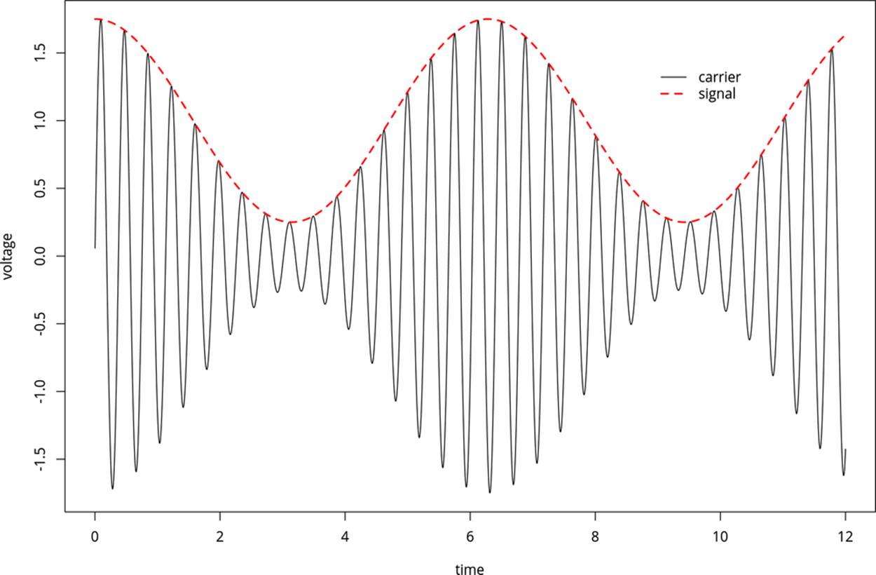
Figure 9-2. AM modulation
AM radio allows for a particularly simple receiver. When you tune the radio to the correct frequency, the antenna receives a time-varying voltage signal that looks like the solid line in Figure 9-2--the carrier modulated by the signal. To get rid of the carrier, you simply run the received voltage through a diode, so that you get only the positive voltages. Now you’ve got a signal that varies from roughly zero to 1.6 V, which you can output directly to a speaker with a capacitor, just as we did in the audio demos.
Indeed, the simplest versions of AM radio receivers are crystal radios, which really only have four parts: an inductor and tuning capacitor to select the right carrier frequency, a diode to separate the signal from the carrier, and a high-impedance earpiece that doesn’t require amplification (and has the blocking capacitor built in). If you’re interested, you can find crystal radio kits that’ll allow you to build an unpowered receiver for less than the cost of a nice dinner out. Or, for even less money, you can pick up any cheap powered radio receiver and some batteries.
OK, so you’ve got an AM radio receiver ready. How do you make the AVR into an AM radio transmitter? The first step is to create the carrier frequency, and for this we’re going to use the built-in timer/counter hardware to generate a square wave at just under 1 MHz, right in the middle of the AM radio frequencies.
1 MHZ?
Try as you might, you are not going to find 1 MHz on your AM radio dial. That’s because the medium-wave band where AM radio normally lives is usually measured in kiloHertz and runs from around 500 kHz to around 1600 kHz.
Set your radio to 1000 kHz to listen to this AVR project.
Once we’ve got that set up, we’ll modulate the amplitude of the carrier wave by turning on and off the output to the “antenna” pin at our audio frequency—this is the same thing as modulating the carrier with another square wave (at audio frequency). Because both our carrier wave and modulation waves are both square waves, the resulting radio signal will look something like Figure 9-3.
Note that this signal is what’s called 100% modulated. When the audio signal is at its maximum, the carrier is fully on, and when it’s at its minimum, the carrier is fully off. (Compare with the sine wave in Figure 9-2, which was sketched with 75% modulation.) We’ll output this signal directly to an antenna, and send it across the room.
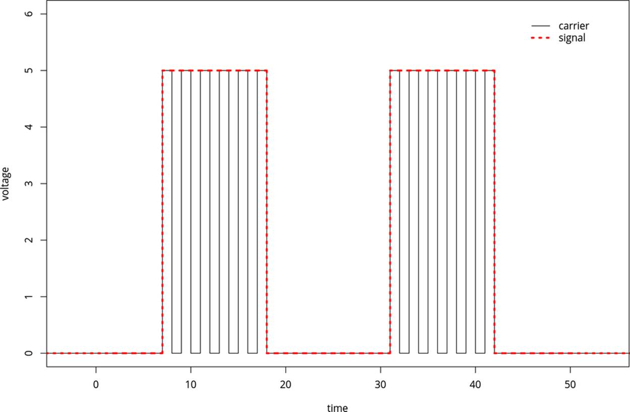
Figure 9-3. AM modulation: square-wave version
The Circuit
How much of a radio you’d like to construct is up to you. Because this project is mostly for fun (and to amaze your nongeek friends), I recommend going all-out minimalist. You can broadcast this signal within a room with just a wire hooked up to pin PD5 / OC0B. A longer wire will broadcast farther and louder, so if you have 10 feet or more of any type of wire just sitting around, that’ll do. If you have a wire that’s long enough to make a loop around the room you’re in, you’ll get phenomenal reception when you’re inside the loop.
Another super-simplistic broadcast antenna option is just to touch pin PD5 with your finger. You’d be surprised how good an AM antenna your body will make! Just as in with adding more wire, you can increase the signal by holding hands with a friend while you touch the antenna pin.
ON THE LEGALITY OF BROADCASTING LOW-POWER AM RADIO
You might be wondering if broadcasting your own bleepy-bloopy AM radio signal is legal. The answer depends on where you live, and what kind of power you’re transmitting. In the USA, for instance, it’s legal to broadcast on the AM bands if you use less than 100 milliwatts. It’s very unlikely that you’ll be putting anywhere near that much power with an AVR unless you’ve got a very long wire, so don’t worry about it.
Power limits aside, we’re making such a lousy AM transmitter that it’s almost surely the case that you won’t interfere with anyone else’s reception. When I did this experiment, I could only receive the signal within the room I was broadcasting in. And because I was only running the “station” for a few minutes, I didn’t worry about it, but I wouldn’t leave this circuit powered and running for too long out of consideration for others. If you’d like to be broadcasting for a long period of time, you should probably get yourself an amateur radio license and move over to a frequency that’s reserved for radio experimentation—then you can use (almost) all the power you need.
CPU Speed
Thus far, we’ve been running code that we needed to slow down to a human time-scale, so we were never all that concerned with how fast the AVR was able to run. Generating a radio signal at 1 MHz provides us the opposite problem—we need the chip running as fast as it can—without resorting to an external crystal.
The internal CPU clock in all of the ATmegaxx8 chips (like our 168s) run at 8 MHz, so we should have no real problem making our 1 MHz signal. But all of the ATmegaxx8 chips come from the factory with a 1/8th prescaler between the CPU clock and the CPU. That’s right—your chip comes fresh out of the box running at 1/8th of its possible speed. The reason is that, as we’ve seen here, most of the time the extra CPU speed isn’t necessary and just wastes power. But when you need speed, as here, it’s nice to be able to put the chip into overdrive.
There are two ways to turn off the prescaler on the ATmega 168 series chips. The first is permanent, and involves changing a so-called fuse in the AVR. The “fuses” are actually a bunch of programmable flash memory locations, just like we store our program in, only they directly control the behavior of the chip and are kept separate from the main program space so that we don’t mess anything up.
The advantage to setting the CPU speed by setting a fuse is that once you’ve set the chip up to run at full speed, you won’t have to remember to do it again. When you flash in another program, the AVR’s CPU clock will still run at 8 MHz as long as you haven’t reset the fuse in the meantime. The disadvantage is that sometimes, for power-reduction reasons, you might like to control the CPU speed on the fly from within your code. And this leads us to the second method of modifying the CPU clock prescaler—through software using the avr/power.h library functions.
The newer ATmega chips, including all of the xx8 series that we’re using here (and most of the new generation of ATtiny chips as well) have the ability to change the CPU prescaler from within software, and to many more possible values than simply 1 MHz or 8 MHz. I’ll go over switching the CPU speed both ways, fuses and from software, because you’ll still see a lot of code out there where people tell you to set the “fast fuse.” But note that you can just as easily add a couple lines to your code and control the speed in firmware.
Setting fuse bits
If you look up in the datasheet, or online, the fuse we’re interested in resetting is called the DIV8 clock fuse bit. If you’re interested in the nitty-gritty details of setting fuses, and you may need to set some of the AVR’s other fuses someday, read Burning Fuses: Enabling the High-Speed CPU Clock. If you’d just like to get the fuse set, and you’re using my makefiles, you can simply type make set_ fast_fuse.
And I should mention that you don’t really need to do any of this for the purposes of the code in this book. I’ll be setting the clock to fast-mode in software as needed.
BURNING FUSES: ENABLING THE HIGH-SPEED CPU CLOCK
Believe it or not, most of the AVR chips come from the factory set to divide the system CPU clock by eight. That’s right, they’re running slowed down 8x by default. Why would Atmel do this to you? Well, for a large majority of projects, the speed just isn’t necessary, and you save a lot on power drain by under-clocking. But here, we’re pushing the limits of what’s reasonable—using the hardware clock to directly produce a radio-frequency signal. We’re going to need all the speed we can get.
Changing up the clock speed turns out to be a matter of burning fuses. The AVR chips have two or three bytes of special memory locations that they call fuse bits. Because they fundamentally alter the way the chip behaves, the fuse bits are kept separate from the main program flash memory, but otherwise they function similarly. You can read and write them with a flash programmer and AVRDUDE just like programming any other flash memory in the chip.
Because the fuse bits alter the way the chips interact with the world, it pays to be a little cautious with the flash memory because there are a two main dangers.
The worst thing you can do is change the SPI-programming bit, which disables your ability to further program the chip using your flash programmer. Why would you want to do this? Because you might want to use the RESET pin for something other than a dedicated reset line, I guess. But if you do so, the programmer can’t signal to the chip that it should enter programming mode without extreme measures. Of course, you can unlock the chip again, using a high-voltage parallel programmer circuit, but this is more work than you’re going to want to get into just for an extra pin of digital I/O. So until you know better, and are prepared for a high-voltage rescue, don’t change the SPIEN-enable fuse bit!
The next worst thing that you can do with fuses is to select the CPU clock to be connected to an external crystal clock source when you haven’t got one installed. The CPU will just sit there waiting for an external clock pulse that never comes. Your code will run, and you won’t be able to reprogram the chip (or the fuses) until you provide an external clock source.
This situation really isn’t so bad, though. If you’ve got a crystal lying around, you can just plug in and then reset the fuses to the internal CPU clock as before. And even if you don’t have an oscillator crystal on hand, you can set up another AVR chip to create a (say) 1 MHz signal and hook that up to the “dead” AVR’s clock input. Then you can reflash the fuse bit to enable the internal clock and you’re back in business.
These two warnings aside, what can you do with the fuse bits that’s useful? In this chapter, we’ll be clearing the default CLKDIV8 fuse that divides the internal CPU clock by eight. Configuring the CPU clock to be driven by an external crystal is also quite common. There are fuse bits that set up how a bootloader (program in the chip itself that will flash the chip—often using a serial connection to replace your flash programmer) will operate.
The most convenient way I know to calculate what the AVR fuse bits should be is using an online fuse bit calculator program that has all the chip data pre-entered. This fuse calculator even goes so far as to provide you the AVRDUDE flags that you’d need to enter on the command line.
For the ATmega48, 88, 168, and 328 series, the default fuse values are:
§ lfuse = 0x62
§ hfuse = 0xDF
§ efuse = 0x01
and you only need to change the lfuse to 0xE2 to enable high-speed mode. The AVRDUDE flag to set the full-speed clock looks like -U lfuse:w:0xE2:m, which tells AVRDUDE to do a flash memory operation, on lfuse, writing the byte 0xE2 immediately (m, as opposed to reading the data from a file). On a Linux or Mac system, type man avrdude or search the Internet for “avrdude man page” to see what all of the command-line arguments do in detail.
Or, using my included makefile, you can simply type make set_fast_fuse or make set_default_fuses to switch back and forth between full-speed (8 MHz) and low-speed (1 MHz) mode.
Setting CPU speed in code
The modern way to change CPU speed is through code. Note that this won’t work if your chip doesn’t support it, and the compiler should throw an error. In that case, you’ll need to use the fuse-bit method to enable the chip’s full potential. But for the entire ATmegaxx8 line of chips, you’ll be able to control the speed dynamically through code. Here’s how.
SOFTWARE CPU CLOCK SPEED CONTROL
If you look through the AVR datasheet, in the section on the System Clock and the Register Description, you’ll find the “Clock Prescale Register,” CLKPR. The lowest four bits of this register (CLKPS3..CLKPS0) allow you to control the clock division by all powers of two from 1 to 256. So even if the main system clock is running at 8 MHz by default, you can run the CPU clock from 8 MHz all the way down to 8/256 MHz, or 31.25 kHz if you’d really like to save power and don’t need the extra speed.
Because monkeying around with the CPU speed is not something you’d want to do by accident, there is additionally a “Clock Prescaler Change Enable” bit that has to be set no more than four CPU clock cycles before the prescaler bits are able to be written. Because all of this timing is tight, the avr-libc library provides functions that make it trivial to change the speed. The CPU prescaler macro functions are included in the avr/power.h library. The advantage of setting them through the prebuilt libraries is that you don’t have to worry about any of the timing details and that nicely named convenience macros are defined for all of the speed grades.
So to set the chip to run at 8 MHz, full speed, you only need to add the following two lines to your code:
#include <avr/power.h>
/* and then in the main() function... */
clock_prescale_set(clock_div_1);
Or if you’d like to run the chip at 1/2 MHz to save power:
clock_prescale_set(clock_div_16);
Notice here that setting the clock speed in software essentially ignores the fuse setting. That is, if you have the fuse set to run the chip at 1 MHz (the default), you can either speed it up or slow it down from software. You can think of the fuse setting as a default speed that the software setting is able to override.
If you set the CPU speed too slow, you should be warned that your flash programmer may be trying to talk too fast for your chip. If this is the case—you’ve slowed the chip way down and you find that your programmer no longer works—you’ll need to slow the programmer down to match. In AVRDUDE, you use the -B flag to reset the bit-clock to a larger (slower) value. If you’re running the chip particularly slowly, you may need to add as much as -B 200 to program the chip if you’ve got it set a clock_div_256.
Also note that everything runs slower (or faster) if you’re changing the CPU speed on the fly from within your code. Functions like _delay_ms(100) may not take as much time as you’d expect, and none of the serial communication routines will work either. These functions use the #define F_CPU macro to figure out how fast they have to run. If you’re changing the CPU speed in your code on the fly, delays and serial routines won’t work unless the currently set speed matches the F_CPU definition in the makefile (or in your code, if you’ve decided to define it there instead).
But for everything we’ll do in this book, we set the CPU speed once in the init section and leave it alone. The corresponding makefile should have the matching F_CPU definition as well, so you won’t need to worry about that. It’s only if you’re mixing and matching that you’ll need to think about the CPU speed. If you need to use the serial port, for instance, at a CPU speed other than that defined in F_CPU, you’ll need to redo the device initialization stuff to match the new CPU speed. (Or just avoid switching CPU speeds on the fly entirely.)
Finally, before we leave the section where I introduced the avr/power.h library, I should mention that there are all sorts of other macros available that allow you to shut down parts of the AVR hardware in order to minimize power usage. For instance, if you’re not using the analog-to-digital converter (ADC) hardware, you might as well turn it off to save a little power:
power_adc_disable();
See the avr-libc homepage for the complete listing of all the parts of the chip that you can turn off to save power.
AM Radio: The Code
This code section really gets to show off what timers can do, and we even get to combine a timer with interrupts. Hold on tight!
In the radio code, we’ll be using Timer 0 in CTC mode as we did earlier to generate audio in the improved organ code. That is, we have the counter count up to a value that determines its frequency, and then clear the counter and start over at zero. Every time it resets, it will toggle a pin. Only this time, it’s toggling the pin at roughly 1 MHz and emitting radio waves rather than audio. This is the carrier frequency.
To modulate the carrier, we’re going to use another timer, Timer 1. Timer 1 is also run in CTC mode to generate variable frequencies. Only instead of toggling a pin directly, it calls an interrupt service routine every time it resets. Inside the ISR, we simply turn on and off the carrier signal to modulate it, generating the audio on top.
All that’s left to do is set the pitch in Timer 1’s OCR1A, and let it run for a given amount of time to sound the note. Let’s see how it goes in detail in Example 9-4.
Example 9-4. amRadio.c listing
/*
Plays a simple tune, broadcasts it in the AM radio band.
*/
// ------- Preamble -------- //
#include <avr/io.h> /* Defines pins, ports, etc */
#include <util/delay.h> /* Functions to waste time */
#include <avr/power.h>
#include <avr/interrupt.h>
#include "pinDefines.h"
#include "scale16.h"
#define COUNTER_VALUE 3 /* determines carrier frequency */
// From f = f_cpu / ( 2* N* (1 + OCRnx) )
// Good values for the AM band from 2 to 6: pick one that's clear
// Divide by two b/c we're toggling on or off each loop;
// a full cycle of the carrier takes two loops.
// 8Mhz / (2 * 1 * (1+2)) = 1333 kHz
// 8Mhz / (2 * 1 * (1+3)) = 1000 kHz
// 8Mhz / (2 * 1 * (1+4)) = 800 kHz
// 8Mhz / (2 * 1 * (1+5)) = 670 kHz
// 8Mhz / (2 * 1 * (1+6)) = 570 kHz
// 8Mhz / (2 * 1 * (1+7)) = 500 kHz
static inline void initTimer0(void) {
TCCR0A |= (1 << WGM01); /* CTC mode */
TCCR0A |= (1 << COM0B0); /* Toggles pin each time through */
TCCR0B |= (1 << CS00); /* Clock at CPU frequency, ~8MHz */
OCR0A = COUNTER_VALUE; /* carrier frequency */
}
static inline void initTimer1(void) {
TCCR1B |= (1 << WGM12); /* CTC mode */
TCCR1B |= (1 << CS11); /* Clock at CPU/8 frequency, ~1MHz */
TIMSK1 |= (1 << OCIE1A); /* enable output compare interrupt */
}
ISR(TIMER1_COMPA_vect) { /* ISR for audio-rate Timer 1 */
ANTENNA_DDR ^= (1 << ANTENNA); /* toggle carrier on and off */
}
static inline void transmitBeep(uint16_t pitch, uint16_t duration) {
OCR1A = pitch; /* set pitch for timer1 */
sei(); /* turn on interrupts */
do {
_delay_ms(1); /* delay for pitch cycles */
duration--;
} while (duration > 0);
cli(); /* and disable ISR so that it stops toggling */
ANTENNA_DDR |= (1 << ANTENNA); /* back on full carrier */
}
int main(void) {
// -------- Inits --------- //
clock_prescale_set(clock_div_1); /* CPU clock 8 MHz */
initTimer0();
initTimer1();
// ------ Event loop ------ //
while (1) {
transmitBeep(E3, 200);
_delay_ms(100);
transmitBeep(E3, 200);
_delay_ms(200);
transmitBeep(E3, 200);
_delay_ms(200);
transmitBeep(C3, 200);
transmitBeep(E3, 200);
_delay_ms(200);
transmitBeep(G3, 400);
_delay_ms(500);
transmitBeep(G2, 400);
_delay_ms(2500);
} /* End event loop */
return (0); /* This line is never reached */
}
Skipping straight down to the main() function, you can see that it plays a bunch of beeps overlaid on our AM carrier frequency, to play a simple song. All of the work of generating the radio and audio tones are done by timers. Let’s take a look at them.
initTimer0() is actually very very simple. We want a variable frequency (so that we can tune to different stations), so we set the timer in CTC mode. We want the hardware to toggle a pin, so we set the COM0B0 flag. Notice that we haven’t set the pin’s DDR to output yet—we’ll get nothing out until we do. The initialization function then sets the clock directly to the CPU clock, with “/1” prescaling, because we need all the speed we can get. Finally, we tune our broadcast station (very roughly) by selecting the output-compare value that we’ll be counting up to. As noted in the comments, this gives us five frequencies that we can tune to in the AM band. You can transmit on other frequencies of course, but your radio may not be designed to pick them up.
initTimer1() has a little more detail to it. Again, we select CTC mode. But notice that the Waveform Generation Mode bits we need to set are different. Timer 1, a 16-bit timer, has many more options than the 8-bit equivalents, and it has four WGM bits that you can set instead of only three. Table 16-4 in the datasheet goes through all of them. I just looked down until I found the CTC mode with a variable TOP value and used that. In order to get the audio pitches in the right range for the values I’d computed, I ended up dividing the CPU clock by eight for Timer 1 and setting the CS11 bit to do it.
Finally, there is one new bit in configuring this timer that we haven’t seen before. The Timer Interrupt Mask (TIMSK) registers allow us to configure all of the different ways to trigger interrupts from the timer/counter. The three options include triggering when the counter hits compare values A or B, or alternatively when the counter overflows.
Because we’re running the timer in CTC mode, it will essentially never overflow. Remember that when the timer hits a compare value, it is reset, right? So unless that compare value is equal to the maximum value (65,535 for the 16-bit timer), it will never overflow. Instead, the overflow interrupts are more useful when the timer is used in PWM mode, which we’ll discuss in Chapter 10.
Anyway, because we wanted to be able to control the pitch of the audio by modifying the compare-and-reset value OCR1A, we enable the interrupt by setting the bit for Output Compare Interrupt Enable 1A (OCIE1A).
The ISR for Timer 1’s compare interrupt A, called TIMER1_COMPA_vect, does our 100% modulation of the carrier for us. That is to say, it toggles the antenna output on and off. And that’s it. A short and sweet interrupt service routine!
Now the two timers are configured and doing their things, right? Timer 0 is looping through very quickly from zero to three, toggling a pin every time it resets. Timer 1 is looping through at audio rates, triggering an ISR every time it resets, right? Well not quite yet. We haven’t enabled the global interrupt bit yet.
That’s where the function transmitBeep() comes in. This function sets the pitch in the OCR1A register and then enables interrupts. Now the ISR toggles the antenna on and off, creating the audio signal over our carrier. There’s a simple _delay_ms() loop to allow for the duration of the note, and then interrupts are turned off again and the carrier is returned to being full on.
If you’re not familiar with radio broadcasting, it might seem strange to leave the carrier on full and claim that it’s not making any noise. But look back at the diagrams of how amplitude modulation works. It’s the change in the carrier wave—the modulation—that carries the pitch. If you just leave the carrier on full, without modulating its volume, that corresponds to a flat line in its outer volume envelope, and a flat line makes no noise. It’s only when we start wiggling the volume envelope at a particular frequency (by reenabling the ISR) that we get a pitch back out.
And that’s it, really. Our AM radio is a tiny bit of a hardware hack (if you consider hooking up a long wire to an AVR pin as a hardware hack) and the rest is done in software. For the audio, we reuse the concept for generating audio from our improved organ program, only instead we turn on and off the tranmitter through an ISR instead of directly driving a speaker. The transmitter is just another CTC-timer generating a really high-frequency square wave toggling our antenna pin. It’s not the cleanest radio station in the world, and certainly not professional, but you can play yourself bleepy music across the room.
Summary
In this chapter, we started in on our first of a two-part series on the timer/counter hardware. We used Normal mode to time short-duration events in the reaction timer. Then, we revisited our original organ program, offloading the job of toggling the speaker pin to a variable-frequency CTC-mode timer/counter with the output pins enabled.
Then finally, we shifted the timer into high gear, enabling the AVR’s full-speed mode through the power.h libraries, and used two timers to make a fully modulated AM radio signal. One timer ran at radio frequencies to create the carrier that you tune your radio to, and the other employed an ISR to turn this carrier on and off at given frequencies to make music.
When configuring timer/counters, so far, the important points to remember are:
§ Set the waveform mode to either Normal mode (the default) or to CTC mode by setting the appropriate waveform mode bits.
§ Select the clock prescaler speed. You must set these bits, because the default value leaves the timer/counter prescaler unconnected, and thus not running.
§ Optionally select an output mode if you’d like to set, clear, or toggle output pins from your timer/counter. (And don’t forget to set the corresponding DDR bits.)
§ If, instead of toggling pins directly, you’d like to have some code executed, you can enable an interrupt to trigger on compare match. (And don’t forget to enable interrupts globally with sei().)
In Chapter 10 we’ll see how to create “analog” voltage output by using pulse-width modulation. The PWM mode of timer/counter modules will come in handy there. We’ll also use timers to control motors in Chapter 11, Chapter 14, and Chapter 15. We’ll use timers plus interrupts again and again, both for making real-time clocks and in conjunction with PWM to make a direct-digital audio synthesizer and even (in Chapter 18) to play back your own voice samples.
In short, this chapter on timers and the preceding chapter on interrupts are the foundation for all of the advanced techniques in the rest of this book. So if it feels like a lot to take in all at once, don’t worry. You’ll get more examples of using both coming right up!
All materials on the site are licensed Creative Commons Attribution-Sharealike 3.0 Unported CC BY-SA 3.0 & GNU Free Documentation License (GFDL)
If you are the copyright holder of any material contained on our site and intend to remove it, please contact our site administrator for approval.
© 2016-2026 All site design rights belong to S.Y.A.