Make: AVR Programming (2014)
Part II. Intermediate AVR
Chapter 10. Pulse-Width Modulation
Fading LEDs and “Analog” Output
So far, everything’s been either on or off in our AVR world—strictly digital. LEDs have been either on or off. Speaker cones have been either pulled fully back or pushed fully forward. Electrons have been pushed this way or that through antennas without particular finesse. On and off is fun, but sometimes you want an LED to fade instead of blink, or a motor to run at half speed instead of being always on or off. Or you’d like to make some audio waveforms other than just the square wave, and you’d like them to have volume control.
To do that, we’ll need to figure out a way to make intermediate voltages from the AVR’s logical high and low, and one of the most common ways of doing so is pulse-width modulation (PWM). In brief, PWM toggles the logic output on and off very fast, so quickly that whatever is attached to the output can’t react fully. The result is that the output sees a voltage that is proportional to the average percent of the time that the AVR spends with its output on. (If that sounds strange right now, it’ll seem perfectly normal by the end of this chapter.)
In Chapter 13, we’ll use PWM to play back audio synthesizer waveforms. In Chapter 14 and Chapter 15, we’ll use PWM to drive motors at different speeds and even backward. Finally, in Chapter 18, timer/counter PWM will help us build a talking voltmeter that reads out voltages to you in your own voice. In sum, we’ll be using PWM in a lot of the upcoming projects, so please excuse me for this chapter if we simply pulse some LEDs.
PWM is such a common method of creating analog voltages from digital devices that almost all microcontrollers, including the AVR, have dedicated internal peripheral hardware that takes care of this high-speed bit toggling for you, and I recommend using this feature whenever you can. In this chapter, we’ll also step through a completely manual PWM routine that’s useful for helping build up your intuition about what’s going on, and I’ve added in another method of using the timer/counter peripheral and its interrupts to output PWM waveforms on any pin that’s capable of output. So let’s get down to the business at hand—flipping bits, fast.
WHAT YOU NEED
In addition to the basic kit, you will need:
§ LEDs and current-limiting resistors hooked up as in previous chapters.
§ A USB-Serial adapter.
Bright and Dim LEDs: PWM
PWM is perhaps the easiest technique for us to implement that’ll give us a partly-on, analog effect. As mentioned earlier, we’ll need to switch a digital output high and low fast enough that whatever device we’re driving can’t react to the individual on-off pulses, but instead only to the average value. We then regularly repeat these pulses and control the average value by varying the percentage of the time in a cycle that the output is held high. The resulting voltages are plotted in Figure 10-1.
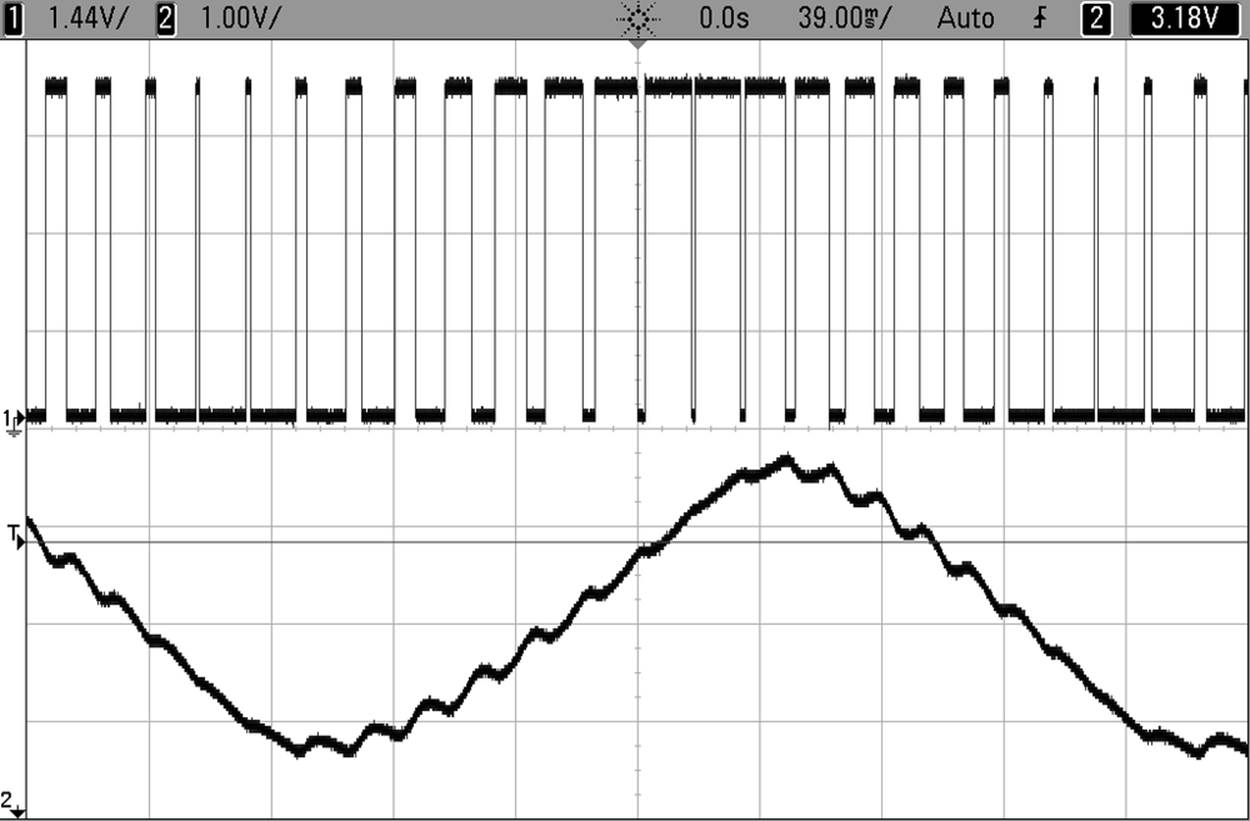
Figure 10-1. PWM oscilloscope traces
In Figure 10-1, the top line is the direct-from-the-AVR PWM trace. You can see how the percentage of time that the AVR output is high changes from low to high, and back down to low again. The lower line is the result of passing the PWM signal through a resistor-capacitor filter, like the one I will suggest for use with an amplifier in Chapter 13. This filter provides the slowed response that turns the PWM signal into an averaged-out analog voltage—when the PWM signal spends more of its time at 5 V, the analog output is higher, and vice versa. While the PWM signal is truly digital—it’s either high or low—the resulting (filtered) average voltage can take on values in between.
There are two parameters that we need to specify in order to use PWM. This percentage of the cycle time that is spent in the on state is called the duty cycle, and the frequency with which we go through a single cycle is usually called PWM frequency. The duty cycle will usually be our control parameter. That is, we vary the duty cycle frequently, possibly even continually, in order to control the “analog” average voltage, just as in Figure 10-1.
For most applications, we’ll choose the PWM frequency just once, at the beginning. As I hinted earlier, what’s crucial with the PWM frequency is that it’s fast enough that whatever system we are controlling doesn’t have time to react to each pulse, but rather only the average value. How fast is fast enough? That depends on the application and our tolerance for ripple, or the little remaining bits of the PWM pulse train that inevitably sneak through. Because I chose the PWM frequency to be so close to the output waveform’s frequency in Figure 10-1, you can see quite a bit of ripple in the output. If I used a much higher PWM frequency, the ripple would be a lot smaller (but it wouldn’t make as good an example).
How high your PWM frequency needs to be for a given amount of ripple depends on how slowly your driven device or filter responds to changes in input. For instance, motors are often only able to adjust their speed relatively slowly due to inertia of the arm or wheel or robot or train that they’re driving. For most motors, PWM frequencies as low as the 50–500 Hz range are probably optimal. Or they would be, except that they’re right in the middle of the range of human hearing, and people like their motors not to sing.
Many modern motor-control circuits use PWM frequencies slightly above 20 kHz (roughly the top frequency of human hearing) to save us the noise of squealing motor windings whenever they can. On the other hand, there are exceptions. Most subway cars have quite audible PWM frequencies, and you can listen to the motors wind up and down—the engineers seem to have been more concerned with driving the train efficiently than the little bit of motor whine.
Creating accurate analog audio for humans, as we will do in Chapter 13, requires even higher PWM frequencies on the order of two times the highest desired frequency, so you often see PWM frequencies higher than 40 kHz. (In our example, for 8-bit audio with the built-in 8 MHz CPU clock, we’re limited to 32.5 kHz. Good enough.)
The human eye, unlike the ear, falls in the slow response category. We saw this in the POV toy example, where we used pulses on the order of 2 milliseconds (500 Hz). It turns out that we don’t need a frequency anywhere near this high to avoid flickering—for me a period of around 18 milliseconds (just under 60 Hz) doesn’t seem to flicker. Remember that here I’m talking about the response time of the human eye, not the LEDs—those can pulse on and off in the megahertz range but we wouldn’t notice it. Here, the human optical system is the slowly adjusting mechanism that we’re using to average out the pulses.
Brute-Force PWM Demo
But don’t take my word for it. Example 10-1 is a fully adjustable, manual PWM routine to play around with. Flash in the program pwm.c and experiment with where your own flicker-fusion frequency lies by changing the delay time defined at the top. Then, let’s look at the event loop and see how it works.
Example 10-1. pwm.c listing
/* Quick and dirty PWM Demo */
// ------- Preamble -------- //
#include <avr/io.h> /* Defines pins, ports, etc */
#include <util/delay.h> /* Functions to waste time */
#include "pinDefines.h"
#define LED_DELAY 20 /* microseconds */
void pwmAllPins(uint8_t brightness) {
uint8_t i;
LED_PORT = 0xff; /* turn on */
for (i = 0; i < 255; i++) {
if (i >= brightness) { /* once it's been on long enough */
LED_PORT = 0; /* turn off */
}
_delay_us(LED_DELAY);
}
}
int main(void) {
uint8_t brightness = 0;
int8_t direction = 1;
// -------- Inits --------- //
// Init all LEDs
LED_DDR = 0xff;
// ------ Event loop ------ //
while (1) {
// Brighten and dim
if (brightness == 0) {
direction = 1;
}
if (brightness == 255) {
direction = -1;
}
brightness += direction;
pwmAllPins(brightness);
} /* End event loop */
return (0); /* This line is never reached */
}
This code is split up into two distinct parts. The function pwmAllPins() takes care of implementing PWM. The remaining code in the event loop increases and decreases a brightness variable. Calling pwmAllPins() with the increasing and decreasing brightnessmakes the LEDs pulse in and out.
In pwmAllPins(), we have a loop over i, which takes exactly 256 steps each time. Inside the i loop, we compare a variable brightness to i and turn on the LEDs if i is smaller. This has the effect of turning on the LEDs at the beginning of each set of 256 and then turning them off as soon as i reaches the value brightness, so for higher values of brightness the LEDs stay on for a greater percentage of the 256 steps. PWM! (But notice that we’ve locked up the entire CPU just brightening and dimming.)
Now, you can modify the per-step delay time and figure out where you just start to notice the flickering. (Or better still, hook up a potentiometer and adjust the delay time by turning the knob.) You’ll soon find your personal flicker-fusion rate. Notice when you move your head that you’ll see the persistence-of-vision trailer effects as well.
When you’re playing around with the delay, remember that you’re taking 256 steps per cycle, so if you delay 20 microseconds per step, that’s 5,120 microseconds, or 5.12 milliseconds per cycle. Because there are 1,000 milliseconds in a second, this gives a PWM frequency of 1,000 / 5.12, or around around 195 Hz.
The main() portion of the code sets up a direction variable (as a signed integer) that lets us add to or subtract from the current brightness. Finally, when the brightness hits either limit, direction reverses sign. The result is a brighter-and-dimmer pulsing fade.
When you’re playing with the LED demo, you may also notice that the human eye doesn’t respond to equal changes in brightness equally. In our simple fade, it looks like the LEDs go through the dark portion of their fade-in and fade-out faster than the light part, even though we know that the duty cycle is changing by +/– 1 delay period each step through the for loop.
The human eye is much better at telling the difference between low levels of light than higher ones. That is, the human eye’s response to light is nonlinear. Many LEDs are driven in PWM mode to exploit this fact—if you notice LED traffic lights flickering when you turn your head past them suddenly, that’s PWM. The reason that PWM-driven LEDs are so prevalent is that your eyes can’t really tell the difference between 90% and 100% duty cycles, so the city can run the traffic lights at 90% and pocket the 10% energy savings.
Timers PWM Demo
If you don’t believe me about your eye’s nonlinear response to brightness, let’s do the experiment. Example 10-2, pwmTimer.c, uses the serial port to take in characters you type and convert them to numeric PWM values. And along the way, you’ll learn about the best way to implement PWM—letting the hardware take care of it.
Flash in the firmware and then type in 10, 20, and 30 in a random order and see if you can tell which is the brightest. Now type in 210, 220, and 230 and repeat. Much easier to tell the dimmer ones apart, right? Your eye’s response to brightness is much closer to reacting to the percent changes in brightness than to the absolute changes. Just something to think about when you’re trying to make LED art—equally spaced PWM values won’t appear evenly spaced in brightness.
You might be wondering why we’re only lighting up three LEDs using the hardware PWM, and the sad reason is that the AVR’s dedicated PWM pins are limited to two per timer, for a total of six: four pins at an 8-bit PWM depth, and two at 16 bits. So the software lights up three LEDs in a row with the PWM values you’ve typed, shifting the new value in, the current values over, and the oldest value out. Now let’s see how it’s done in Example 10-2.
Example 10-2. pwmTimers.c Listing
/* PWM Demo with serial control over three LEDs */
// ------- Preamble -------- //
#include <avr/io.h> /* Defines pins, ports, etc */
#include <util/delay.h> /* Functions to waste time */
#include "pinDefines.h"
#include "USART.h"
static inline void initTimers(void) {
// Timer 1 A,B
TCCR1A |= (1 << WGM10); /* Fast PWM mode, 8-bit */
TCCR1B |= (1 << WGM12); /* Fast PWM mode, pt.2 */
TCCR1B |= (1 << CS11); /* PWM Freq = F_CPU/8/256 */
TCCR1A |= (1 << COM1A1); /* PWM output on OCR1A */
TCCR1A |= (1 << COM1B1); /* PWM output on OCR1B */
// Timer 2
TCCR2A |= (1 << WGM20); /* Fast PWM mode */
TCCR2A |= (1 << WGM21); /* Fast PWM mode, pt.2 */
TCCR2B |= (1 << CS21); /* PWM Freq = F_CPU/8/256 */
TCCR2A |= (1 << COM2A1); /* PWM output on OCR2A */
}
int main(void) {
uint8_t brightness;
// -------- Inits --------- //
initTimers();
initUSART();
printString("-- LED PWM Demo --\r\n");
/* enable output on LED pins, triggered by PWM hardware */
LED_DDR |= (1 << LED1);
LED_DDR |= (1 << LED2);
LED_DDR |= (1 << LED3);
// ------ Event loop ------ //
while (1) {
printString("\r\nEnter (0-255) for PWM duty cycle: ");
brightness = getNumber();
OCR2A = OCR1B;
OCR1B = OCR1A;
OCR1A = brightness;
} /* End event loop */
return (0); /* This line is never reached */
}
As with the rest of the timer/counter-based code demos so far, the event loop is quite sparse. It gets a value from the serial port and then shifts the values up a chain, corresponding to the output compare registers of LED1, LED2, and LED3. Note how we don’t need to use any more variables to store the “previous” values that we received over the serial line—they’re stored in the OCRnx registers just as if they were normal variables.
Writing those three variables takes just a couple microseconds even at 1 MHz. The rest of the CPU time is spent waiting for and processing our serial input. Note how we couldn’t do this at all with the software-based PWM approach in pwm.c; if we waited for serial input, the LEDs would stop blinking. Even if we just checked if the serial port had new data, it would throw off our PWM timings. Here, all our code has to do to keep the LEDs blinking at their appropriate duty cycle is write values to the appropriate OCRnx registers. The hardware takes care of the rest—counting, comparing, turning on and off pins. In this example, that leaves us free to use the CPU to talk to us over the serial port.
Initializing Timers for PWM Mode
Configuring PWM by timer is a lot like using the hardware timer/counter in Chapter 9 except that we’re selecting a PWM waveform generation mode instead of Normal or CTC modes.
Turn your attention to the initTimers() function, and you’ll see something similar to what we did in Chapter 9. We set up the timers’ waveform modes, set the clock input prescaler, and then set the compare output bits to enable direct output on the OCR1A, OCR1B, and OCR2A pins. Voila.
FAST PWM MODE
Fast PWM mode is probably the most-used PWM mode, as well as the most straightforward. The counter loops around from zero to its maximum value (255 or 65,535 or another value stored in the OCRxA register, depending on the particular timer and mode) continuously at the speed defined by the prescaler. Along the way, the counter is compared with the contents of the Output Compare (OCRnx) registers. When a match happens, the PWM output pins can be set or cleared and interrupts can be fired.
Fast PWM mode is fundamentally a hardware version of the pwm.c demo code, which continuously looped around from 0 to 255 and compared the counter value to a duty cycle variable. But using the hardware PWM mode can be much faster than doing the same thing in code and uses no CPU cycles.
Calculating the PWM frequency for fast PWM mode is easy. Take the CPU clock frequency, divide it by a prescaler value if applicable, and then divide by the number of steps per cycle. For example, I’ve set the prescaler at 8, using an 8-bit timer with 256 steps, and a 1 MHz CPU clock; therefore, the fast PWM frequency is 1,000,000 Hz / 8 / 256 = 488 Hz.
Have a look through the datasheet and make sure you understand at least where to find the bits that are being set in the initialization routine. You’ll notice that Timer 1 is more complicated because it’s a 16-bit timer—the AVR gives us modes to operate it in 8-bit, 10-bit, or full-resolution modes. We’ll use its full resolution later on to drive servo motors in Chapter 11, but for now, notice that we have it set up in an 8-bit PWM mode that uses 255 as its maximum value so that it’s consistent with the other LED on Timer 2.
Setting the compare output mode with the COM bits is also a little different here than in the CTC case. For one thing, there are different tables for what the bits mean in the CTC, fast PWM and phase-correct PWM cases, so make sure you’re looking at the right COMtables. In our case, setting COM1A1, COM1B1, and COM2A1 correspond to the “noninverting” mode—that is, the PWM turns the pin on when it overflows from 255 to 0, and turns it off when it reaches the compare value. This is just what we did in the brute-force PWM example that lead this chapter, and results in higher PWM values corresponding to higher duty cycles and thus brighter LEDs.
Setting up the clock speed prescaler is just the same as it was in the CTC examples, so there’s not much that’s interesting here. When we configured the prescaler in CTC mode, we were interested in the frequency for its own sake, but here it’s not super critical. With the PWM frequency, it’s only important that the PWM cycles are fast enough that our system responds to the average value. Play around with the different prescaler settings to get a feel for what range of frequencies are good for driving PWM’ed LEDs. Or take an engineering approach and see Fast PWM Mode on how to calculate the PWM frequency.
Before we leave the initialization section, note that we enable output for the three LEDs using the DDR registers. By now you might have noticed that even if you hit Return or type “0,” the dimmest the LEDs go is still not off. Why is that? When you set the OCR to zero, it doesn’t actually turn the pins off. Instead, the pins get turned on as soon as the hardware counter flips over from 255 to zero, and then turned off after the compare match unit compares a zero. That is, each pin is on for 1/256th (0.4%) of the time and this produces visible brightness on the LED.
So what can you do if you want the LED off, like really off-off? The easiest way is to disconnect the pin by putting it in input mode by clearing its corresponding bit in the bank’s DDR register. In some cases, you’ll want to send an actual ground-voltage, low signal; for instance, if you want to turn off a FET that’s attached to the pin. To get a constant logic low voltage, you need to clear the COM bit in the timer’s configuration register to decouple the pin from the timer, and make sure the DDR is set for output and the PORT bit is clear as you normally would.
The good news here is that there’s no such precaution necessary for the case when you want the LED always on. Setting the OCR to 255 does result in output that’s always high. It’s only when you want the pin entirely off that you need to override the hardware PWM.
And with this example under your belt, you should be able to set up and use hardware PWM anywhere in your code. Notice how little your main code actually needs to do to set or change the PWM average-value output once it’s configured. All that’s left for your code is to write a value to the output-compare register, and the hardware takes care of the rest. This makes using PWM conceptually very simple: if you want to output a voltage halfway between 5 V and 0 V, write OCR1A = 127 and you’re done. It’s like you were setting the output’s “analog” voltage directly from your code.
“ANALOG” OUTPUT ON THE ARDUINO
If you’ve used the Arduino platform, you’re probably wondering why we don’t just use the Analog Out pins. Here’s the deal—there are no Analog Out pins. By opening this book, you’ve taken the Red Pill, and you’re going to find out how deep this rabbit hole goes, right? The Arduino folks have been lying to you! It’s all a giant conspiracy to keep you from learning about PWM. Now you know the truth!
OK, more seriously, the Arduino platform aims to abstract away a lot of the nitty-gritty details, and so they don’t bother you with the difference between “analog” and PWM output, or require you to know which pins are connected to which timers. Have a look at the analogWrite() function in the Arduino source code file wiring_analog.c in thearduino-1.0/hardware/arduino/cores/arduino directory. (Change to match your version number.) You’ll see that we’re all doing the same thing after all.
analogWrite() first checks to see if the value you’re writing is 0 or 255, always off or always on. Then it figures out which timer (digitalPinToTimer(pin)) you need to configure for the pin you specified, and then sets the relevant COM bits and finally the OCR register value. Just like we’ve been doing here! (The Arduino library version sets the COM bits every time you change the duty cycle, which is redundant but makes sure that it’s set.)
The price paid for the Arduino pin/timer abstraction is that what we do in one or two lines of code, and two or three cycles of CPU time, the Arduino does in 50+ clock cycles. It tests if you want the pin fully on or off, and it uses a whole switch() expression and memory lookup to figure out which timer registers to write to—and all of this just so that you don’t have to look up the pin in the datasheet.
If you’re calling analogWrite() infrequently in your code, this will probably work OK, and you’ll never notice the speed penalty. If you’re setting the OCR bits frequently, as we will be in Chapter 13, this extra code overhead means the difference between the possible and impossible. If you’re coming from the Arduino world, you’ll probably be annoyed by how much detail about the chip you’re required to learn, but once you learn how to actually use the hardware peripherals as they’re intended, you’ll be surprised by how much more is possible. And once you know how the internal peripherals work, it’s not much harder to configure them yourself.
PWM on Any Pin
So far we’ve seen two ways to implement PWM in our AVR code. One method implements PWM entirely in code by looping and directly setting the pins on and off using the CPU. The “normal” hardware PWM method works significantly faster, but only on six designated pins, two for each timer.
If we want to implement PWM on an arbitrary pin, there is a trick, but it’s a little bit of hack. Instead of using the built-in pin-toggling function of the timer/counter, we’ll instead use the interrupts to trigger our own code, and turn on and off pins from within ISRs. We don’t have to tie up the CPU with counting and waiting, as we did in the brute-force PWM example. Rather, we can use a timer/counter in Normal mode to do the counting for us.
Then we trigger interrupts at the beginning of the cycle to turn the PWM pins on and use the output-compare values to trigger another interrupt to turn the pins back off. So this method is a little bit like a hybrid of the brute force and fully hardware PWM methods: the counter and ISRs make it take less than the full CPU time just for the PWM, but because the ISRs take some CPU time, it’s not as fast or rock solid as fully hardware PWM.
Because we’re using ISRs to turn on and off the pins in question, we have to be a little bit careful that the PWM values are long enough that the ISRs have time to execute. Imagine that we set the PWM duty cycle to some small number like 6, and the counter’s CPU clock divider to its fastest mode. We then only have six CPU cycles to execute the ISR that turns the LED on at the beginning of the cycle, and this won’t work—most ISRs take at least 10 cycles just in program overhead. (We can further hack around this limitation, but at some point it’s not worth it.)
So the trick to making this any-pin PWM work is making sure that we’ve set up the clock prescaler to at least divide by 64. Then we’ll have plenty of time for our interrupts, and all is well.
PWM on Any Pin Demo
To recap, the PWM-on-any-pin code works by setting up a timer/counter in Normal mode—counting up from 0 to 255 continuously—and interrupts are set to trigger off the timer. First, the overflow interrupt triggers when the timer rolls over back to 0. In this ISR, we turn the pins on. An output-compare ISR then turns the pin back off once the counter reaches the values stored in the output-compare register. That way, a larger value in the OCR registers mean that the pin is on for more of the cycle. PWM! See Example 10-3 for the code listing.
Example 10-3. pwmOnAnyPin.c listing
// Quick and dirty demo of how to get PWM on any pin with interrupts
// ------- Preamble -------- //
#include <avr/io.h>
#include <util/delay.h>
#include <avr/interrupt.h>
#include "pinDefines.h"
#define DELAY 3
volatile uint8_t brightnessA;
volatile uint8_t brightnessB;
// -------- Functions --------- //
static inline void initTimer0(void) {
/* must be /64 or more for ISR timing */
TCCR0B |= (1 << CS01) | (1 << CS00);
/* both output compare interrupts */
TIMSK0 |= ((1 << OCIE0A) | (1 << OCIE1B));
TIMSK0 |= (1 << TOIE0); /* overflow interrupt enable */
sei();
}
ISR(TIMER0_OVF_vect) {
LED_PORT = 0xff;
OCR0A = brightnessA;
OCR0B = brightnessB;
}
ISR(TIMER0_COMPA_vect) {
LED_PORT &= 0b11110000; /* turn off low four LEDs */
}
ISR(TIMER0_COMPB_vect) {
LED_PORT &= 0b00001111; /* turn off high four LEDs */
}
int main(void) {
// -------- Inits --------- //
uint8_t i;
LED_DDR = 0xff;
initTimer0();
// ------ Event loop ------ //
while (1) {
for (i = 0; i < 255; i++) {
_delay_ms(DELAY);
brightnessA = i;
brightnessB = 255 - i;
}
for (i = 254; i > 0; i--) {
_delay_ms(DELAY);
brightnessA = i;
brightnessB = 255 - i;
}
} /* End event loop */
return (0); /* This line is never reached */
}
There are also a couple of details to clean up. First, notice that there are two global variables defined, brightnessA and brightnessB, that will be used to load up the output-compare registers at the beginning of every cycle. Why not write to OCR0A and OCR0Bdirectly? Depending on the timing of exactly when the variable is written and its value, the PWM can glitch for one cycle. A way around that is to always set the output-compare registers at a predictable point in the cycle—inside the overflow ISR. These two global variables can be set by our code in main() whenever, but they’re only loaded into the OCR0 registers from inside the overflow ISR. It’s a simple buffer.
Triggering three different interrupts from one timing source is surprisingly easy. In the initTimer0 code, we can see that it basically amounts to setting three different bits in the TIMSK (timer interrupt mask) register. As mentioned previously, the clock source for the timer has to be significantly slower than the CPU clock to allow the ISRs time to run, so I’ve use a divide-by-64 clock setting. Finally, as with all situations when you’re using an interrupt, don’t forget to enable the global interrupt bit using the sei() function.
The rest of the code is straightforward. The ISRs should be kept as short as possible because they’re being called quite frequently. Here, the compare interrupts have only one instruction. Finally, the main() function demonstrates how to use the any-pin PWM functionality. We simply set the global variable to the desired level whenever it suits us, and the timer and interrupts take care of the rest.
Closing: Alternatives to PWM and a Timer Checklist
In this chapter, I’ve introduced you to three different methods of producing “analog” output by toggling a digital pin quickly. First, we coded everything up from scratch, using the full CPU time just to create PWM output. Next, we handed all of the duties off to the timer/counter PWM. This is by far the most common and powerful method of creating PWM output, but it’s limited to two designated hardware-PWM pins per timer. Bear these restrictions in mind when you’re laying out your own circuits, and the hardware PWM facilities will serve you well.
Finally, as a bit of a hack, I demonstrated a method to get PWM output on any pin by using a timer/counter and its automatically triggered interrupts to toggle any pin or pins for you. The costs here are a little more CPU overhead than the direct hardware method, reduced maximum speed due to the time needed to run the ISRs, and the need to use a couple of global variables to avoid glitches when setting up the output compare registers. On the other hand, when you really need PWM on a nonstandard pin or pins and you’ve got a free timer, using the timer in Normal mode coupled to fire off interrupts is a totally valid option.
So with three options in this chapter, we’ve pretty much exhausted PWM. In closing, though, I’d like to mention a few other options for getting analog output from the AVRs. If you’re in need of higher performance, either in terms of reduced digital noise or higher frequency output, there are other options you should know about.
Digital-to-analog converters (DACs):
Simple voltage divider
If you only need to produce four discrete voltage levels, you can connect both the high end and low end of a restive voltage divider to two AVR output pins. When both are driven high, the output will be VCC. When both are driven low, the output will read 0 V. When only one of the two outputs is driven high, the output of the voltage divider will be between the two extremes.
Imagine creating a voltage divider with twice as much resistance in one leg as in the other—creating a 1/3 voltage divider. Driving one pin high will output 1/3 × 5 V and driving the other pin high will output 2/3 × 5 V.
If you only need one intermediate analog value but you need it to be accurate, you can hand-pick the voltage divider resistors to get exactly the voltage you need. You could even use a potentiometer to make it tunable.
DIY R-2R DAC
Expanding on the logic of the simple voltage divider, you can make a multi-input nested voltage divider using a lot more resistors that’ll let you write out a binary value to the voltage-divider ladder and get the corresponding voltage out. The trick is to pick the resistance values to generate the right intermediate voltages.
For instance, to make an 8-bit R-2R DAC, you hook up all eight pins of PORTB to resistors of value 2R, and connect these together with resistors of value R, with another of 2R to ground at the least-significant bit. (Look up a schematic on the Web if you’d like to make one.) The end result is that each pin on the AVR contributes to the output voltage in a binary-weighted fashion so that you can simply write out the voltage you’d like to the AVR’s port. Writing 63 to PORTB produces 5 V/4 with a 5 V VCC, for instance.
Building an R-2R DAC is easy enough, and you can get enough accuracy for eight bits using 1% tolerance resistors for all the values. You can do even better by using the same resistors all around, but using two in parallel to make the R values. If you look up plans on the Web, don’t forget that almost all of them require an amplifier following the output, or else you risk loading down the output of the R-2R network with your speakers, for instance.
In addition to simplicity, the advantage of an R-2R-style DAC is that the bits are loaded, and the voltage generated, in parallel—you can change the output voltage almost as fast as you can write a new value to the port that’s driving it, which enables you to create signals with frequencies up into the megahertz range. There is also no ripple at a fixed output level, and the transitions between output voltage levels is usually well behaved. The disadvantage, of course, is that the DAC takes up eight pins that you might want to use for something else.
External DAC chips
Although the DIY R-2R DAC might work for 8-bit output, you have to match resistors carefully to get 10-bit resolution, and much more than 12-bit is nearly impossible. So for high-quality audio output, you’ll want to use a ready-made chip DAC. Some of these are just factory-trimmed R-2R DACs on the inside, whereas others have some digital logic that do high-frequency digital conversion for you.
Because they’re quite frequently used in consumer audio products, you’ll find DACs that are well-suited to generating stereo audio signals (16-bit to 24-bit, 44.1 to 96 kHz) for just a few dollars. These modern audio DACs mostly take their input data through SPI or I2C serial data lines, and you’ll learn about these protocols in Chapter 16 and Chapter 17.
When shopping for a DAC chip, it’s important to consider your desired conversion speed and need for DC accuracy in addition to the resolution in number of bits, because if you try to have everything, you’ll end up with a very expensive chip! That said, DACs for audio use aren’t very sensitive to absolute accuracy, and the maximum frequency is not difficult to attain, so they’re nice and cheap. It’s only when you need a DAC that’s microvolt accurate or operating into the megahertz range that you’ll need to compromise.
Finally, to round out the last couple chapters, which have centered around different uses of the timer/counter hardware, here’s a checklist of all the configuration demands to make use of them. This is not meant to substitute for the “Register Description” pages in the datasheet, but should help to guide you through them.
Timer configuration checklist:
1. First, decide on which timer to use. This will mostly depend on how many bits of resolution you need. If the answer is “8-bit is fine,” then use Timers 0 or 2. If you need 16-bit resolution, or just aren’t using it for anything else anyway, take Timer 1.
2. Next, decide which mode you need: set WGMn0 and WGMn1 bits in TCCRnA and WGMn2 in TCCRnB. See the table “Waveform Generation Mode Bit Description” in the datasheet.
a. Counting or timing events? You’ll want Normal mode. (No configuration bits necessary.)
b. Are you using the timer as a timebase or frequency generator? That’s easiest in CTC mode. Set the WGMn1 bit in TCCRnA.
c. Are you using the timer for PWM? Usually I use fast PWM mode. Set the WGMn0 and WGMn1 bits in TCCRnA if you don’t need adjustable PWM frequency, and additionally set WGMn2 in TCCRnB if you do.
3. Want direct output to the pins? Set COMxA and COMxB bits in TCCRnA accordingly.
4. Determine which clock speed divisor you need and set it with the CSnx bits in TCCRnB.
5. If you’re using a compare value, it’s nice to set a default value in OCRnA and/or OCRnB. Don’t forget to set the corresponding DDR to output mode when you want the pins to output the PWM signal.
6. Using interrupts with your timers?
a. Enable counter overflow interrupt if using Normal mode with bit TOIEn in TIMSKn.
b. Enable output compare interrupts if using PWM or CTC modes with bits OCIEnA and OCIEnB in TIMSKn.
c. Don’t forget to enable global interrupts via sei(); and write your interrupt service routines.
All materials on the site are licensed Creative Commons Attribution-Sharealike 3.0 Unported CC BY-SA 3.0 & GNU Free Documentation License (GFDL)
If you are the copyright holder of any material contained on our site and intend to remove it, please contact our site administrator for approval.
© 2016-2026 All site design rights belong to S.Y.A.