Make: AVR Programming (2014)
Part II. Intermediate AVR
Chapter 11. Driving Servo Motors
Real-Time Clocks and a Laser “Sundial”
Servos are an essential part of any small robot, and they’re literally tailor-made for running with logic-level signals. They’re so easy to drive with the AVR that they make the perfect introduction to microcontroller-driven movement. Figure 11-1 is a family portrait of a few servo motors that I had lying around.
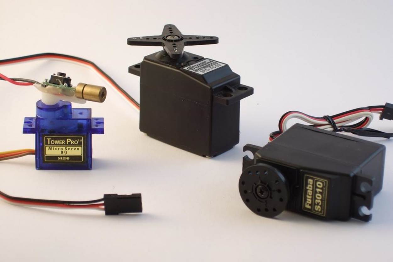
Figure 11-1. Some servo motors
In this chapter, we’ll use the servo’s reasonably accurate positioning to make a laser sundial—a laser dot that moves around your room that you can use to tell the time. Along the way, we’ll work on calibrating the AVR’s internal CPU clock well enough that you can use it as a standalone real-time clock that will keep time to within about a second per day. And that’s pretty useful even if you already have a decent clock in your office.
WHAT YOU NEED
In addition to the basic kit, you will need:
§ A servo. Any old hobby servo will do.
§ (Optionally, but a good idea) a separate power supply for the servo. I used 4xAA batteries. This helps keep the AVR’s power supply clean of motor-generated voltage noise.
§ A laser pointer that you’re willing to take apart. Use a cheapie. I used a cat toy that was given to me.
§ A 2N7000 MOSFET to turn the laser on and off.
§ A USB-Serial adapter to set and calibrate your clock in combination with your desktop or laptop computer.
Servos
Servos are positioning motors with a built-in feedback circuit, and it’s this internal circuitry that makes them so simple to use. As positioning motors, they don’t spin around and around like traditional motors. Instead, they only rotate through 180 degrees or so, and they can move to the desired position to roughly the nearest degree on command. This makes them ideal for pulling up the landing gear on a model airplane, or for moving robot arms. (Your elbow doesn’t spin continuously; why should your robot’s?)
You send position controls to a servo with a signal pulse that ranges nominally from 1 ms to 2 ms. When you send a 1 ms pulse, the motor turns to its most-counterclockwise position, and when you send a 2 ms pulse, it turns the shaft to its most clockwise. If you send a pulse of 1.5 ms, the motor turns the shaft to the center, and so on. These are “nominal” values—you’ll find that they vary a little bit from servo to servo, but assuming that 1.5 milliseconds is somewhere in the middle is a good starting point.
The circuitry inside the servo is expecting a pulse like this every 10–20 ms, and as long as it receives a pulse, it tries to turn the motor shaft to the right position. When no pulse is seen for a while, the servo disengages and can be turned more or less freely. From our perspective, this means that we need to be able to send a short voltage pulse signal of fairly precise duration that controls the position of the servo, and to send these pulses every 20 milliseconds or so.
Why do I say that servos are a perfect match for microcontrollers? First, because outputting this kind of simple control pulse is a job that’s basically tailor-made for the hardware timer circuitry. But most importantly, the AVR doesn’t need to supply any of the driving power for the servo, just the control signal. The servo’s internal circuitry takes care of driving the motor for us. This is in contrast to DC and stepper motors that we’ll see in Chapter 15, where we need all sorts of intermediary circuitry to get a motor to turn. With a servo, we plug it in to power, connect one signal line up to the AVR, and we’re running.
The Secret Life of Servos
If you’re wondering how servos convert the periodic pulses into motor positions, you’ll have to crack open the casing and peek inside. The feedback circuit inside a servo is based on comparing two voltages: one that’s proportional to the control signal that you’ve sent, and one that’s proportional to the motor shaft’s pointing direction. Every time the servo circuit receives a pulse, it turns its motor for a little while in the right direction to make the two voltages more equal.
The shaft-position voltage is simple enough to generate. A potentiometer is connected to the output shaft of the motor inside the servo’s black box. Just like we did in Chapter 7, the potentiometer is wired up as a voltage divider, and the voltage read off the middle terminal is controlled by turning the potentiometer, which is connected to the motor.
(For completeness, I should mention that the drivetrain inside the servo has a set of gears that connects the quick-but-weak motion of a tiny little motor into the stronger-but-slower turning of the output shaft. The geared-down output shaft, not the motor, is connected to the position-sensing potentiometer. The small motor actually turns many times for one half turn of the output shaft. But don’t let that confuse the issue; the practical effect is that the stepper motor’s shaft is connected to a potentiometer.)
Now let’s look at the control signal. When we send a control pulse, the integrator circuit starts to charge a capacitor with a fixed current. As soon as the control pulse drops low, the integrator circuit turns off the current. The result is that the voltage in the capacitor depends on how long it has been charged.
The motor potentiometer voltage and the integrated control pulse voltage are then fed into a comparator, which is just about what it sounds like: a circuit that outputs a high voltage level if the first input voltage is higher than the second, and a low voltage level otherwise. This high or low digital signal then controls the motor direction.
The other thing that happens at the end of a control pulse is that the motor is turned on, but it’s kept on a timer. For instance, for the servo on my desk, the motor runs for 23 ms per signal pulse. This timer is the reason for the 20 ms update rate—if we keep the control pulses coming in faster than this timer, the motor will always be moving in the right direction. And that’s the essence of servo control.
But if this were the end of the story, the motor would be continually running back and forth, oscillating around the control set point. If the position voltage is a tiny bit low, the motor turns clockwise until the position voltage is a tiny bit high and then the motor turns counterclockwise, and so on. It’s a noisy waste of battery power to have the motor continually “seeking” like this. The solution is to implement a dead band where the internal circuitry decides that it’s close enough and turns the motor off.
Because of this dead band, the positioning accuracy of a servo motor isn’t infinite—it won’t bother to reposition itself for tiny changes in the control pulse width. The width of the dead band will vary from motor to motor, but I’ve found that trying to get much more than a few hundred distinct positions from a cheap servo is a losing battle. You can test it out yourself with your motor using the code in this section.
And that explains all the mysteries of the servo-motor! The pulse length is critical because it determines the position. The inter-pulse timing is not nearly so critical, but if you’d like the motor to be always holding its position, the pulses need to arrive every 20ms or so. And finally, the dead band limits how finely you can control the position, but also reduces power consumption by preventing the motor from endlessly seeking.
So servos need a pulse between 1 ms and 2 ms long, and they need this pulse repeated regularly roughly every 20 ms. How are we going to do this? With timers! By far the easiest and most accurate way to drive a servo is simply to hook it up to the output from Timer 1, the 16-bit timer, set the timer’s period to be 20 ms, and then use the PWM output pins and register to send the pulses. You can do this easily with up to two servo motors, because the timer has two dedicated output compare pins. Let’s see how.
The Circuit
Servos have three pins: voltage supply, ground, and signal. We can connect the first two pins directly up to any 4–6 V power supply. The third pin, signal, we’ll connect directly to the AVR. On a breadboard, you’ll end up with something like what’s show in Figure 11-2.
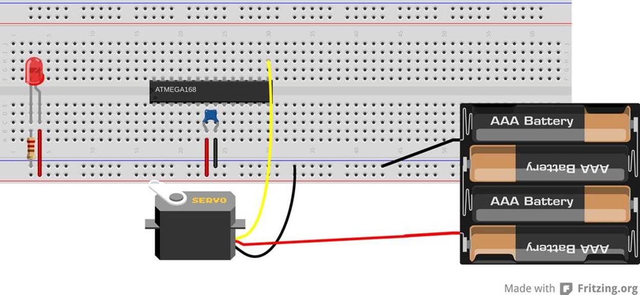
Figure 11-2. Simple servo hookup
To take advantage of Timer 1, which has its output compare channels on PB1/OC1A and PB2/OC1B, you may need to disconnect LED1, and connect it to the servo’s control pin. Or you might get lucky and they’ll work together. It all depends on how much current you’re drawing for the LED, which in turn depends on the LED current-limiting resistors you’ve chosen.
As mentioned earlier, you should also hook the servo up to a supply of 4–6 V. This can be the same power supply that you’re using for the AVR, but it’s sometimes nice to run your robot’s logic and motors on separate circuits so that if your motor stalls out and pulls hard on the battery, it won’t subject the AVR to a brownout. If you are trying to get by with the same power supply for both the servo and the AVR, note that it’ll need to be able to supply at least 500 mA, because a servo can easily draw that much current.
The best practice, though, is to use a separate power supply for the servo. Four AA cells will do the trick nicely. When using a separate power supply for the servo, be sure that the ground for the motor and battery are connected to the ground for the AVR so that they share a common reference voltage level. Otherwise, the AVR and the servo won’t be able to agree on what constitutes a voltage pulse on the signal line.
The Code
Physically connecting a servo to the AVR is simplicity itself. Now all we have to do to make it work is set up the AVR’s internal timer to create the control pulses. Let’s have a look at the code in Example 11-1.
Example 11-1. servoWorkout.c listing
/* Quick interactive demo running servo with Timer 1 */
// ------- Preamble -------- //
#include <avr/io.h>
#include <util/delay.h>
#include <avr/interrupt.h>
#include "pinDefines.h"
#include "USART.h"
#define PULSE_MIN 1000 /* experiment with these values */
#define PULSE_MAX 2000 /* to match your own servo */
#define PULSE_MID 1500
static inline uint16_t getNumber16(void);
static inline void initTimer1Servo(void) {
/* Set up Timer1 (16bit) to give a pulse every 20ms */
/* Use Fast PWM mode, counter max in ICR1 */
TCCR1A |= (1 << WGM11);
TCCR1B |= (1 << WGM12) | (1 << WGM13);
TCCR1B |= (1 << CS10); /* /1 prescaling -- counting in microseconds */
ICR1 = 20000; /* TOP value = 20ms */
TCCR1A |= (1 << COM1A1); /* Direct output on PB1 / OC1A */
DDRB |= (1 << PB1); /* set pin for output */
}
static inline void showOff(void) {
printString("Center\r\n");
OCR1A = PULSE_MID;
_delay_ms(1500);
printString("Clockwise Max\r\n");
OCR1A = PULSE_MIN;
_delay_ms(1500);
printString("Counterclockwise Max\r\n");
OCR1A = PULSE_MAX;
_delay_ms(1500);
printString("Center\r\n");
OCR1A = PULSE_MID;
_delay_ms(1500);
}
int main(void) {
// -------- Inits --------- //
uint16_t servoPulseLength;
OCR1A = PULSE_MID; /* set it to middle position initially */
initTimer1Servo();
initUSART();
printString("\r\nWelcome to the Servo Demo\r\n");
showOff();
// ------ Event loop ------ //
while (1) {
printString("\r\nEnter a four-digit pulse length:\r\n");
servoPulseLength = getNumber16();
printString("On my way....\r\n");
OCR1A = servoPulseLength;
DDRB |= (1 << PB1); /* re-enable output pin */
_delay_ms(1000);
printString("Releasing...\r\n");
while (TCNT1 < 3000) {;
} /* delay until pulse part of cycle done */
DDRB &= ~(1 << PB1); /* disable output pin */
} /* End event loop */
return (0); /* This line is never reached */
}
static inline uint16_t getNumber16(void) {
// Gets a PWM value from the serial port.
// Reads in characters, turns them into a number
char thousands = '0';
char hundreds = '0';
char tens = '0';
char ones = '0';
char thisChar = '0';
do {
thousands = hundreds; /* shift numbers over */
hundreds = tens;
tens = ones;
ones = thisChar;
thisChar = receiveByte(); /* get a new character */
transmitByte(thisChar); /* echo */
} while (thisChar != '\r');
transmitByte('\n'); /* newline */
return (1000 * (thousands - '0') + 100 * (hundreds - '0') +
10 * (tens - '0') + ones - '0');
}
Configuring the timer is the most complicated part of running a servo—after that, the hardware takes care of everything for us. Because we haven’t used Timer 1 yet, you might have a look at its chapter in the datasheet. Timer 1 is a 16-bit timer, which gives us enough precision to use it for the 20 ms period and still control the servo control pulse down to microsecond resolution, all without loading the CPU at all. Woot.
For configuration, the most important difference between Timer 1 and the 8-bit timers is that it’s got a lot more waveform generation modes. In particular, because 16-bit resolution is often overkill, we can additionally configure Timer 1 in 8-bit, 9-bit, and 10-bit modes as a convenience. (We won’t be using those modes here.)
The other main difference is the addition of a separate ICR1 register, which can be used to set the PWM frequency. The details involve how the AVR, an 8-bit machine, deals with 16-bit numbers, but the upshot is that we can use ICR1 to set the frequency for most PWM modes when we’re not changing the frequency often, and use OCR1A to set the frequency if we are changing it a lot. (OCR1A and OCR1B are double-buffered, which means they won’t get clobbered if, for instance, an ISR gets called in between writing the most significant eight bits and the least significant eight bits.)
OK, so we configure Timer 1 for Fast PWM mode with the top value (which determines the PWM frequency) stored in ICR1. It’s convenient, running the chip at 8 MHz, to divide the clock by eight so that each timer tick is 1 microsecond. This lets us set ICR1 to 20,000 microseconds, so that our complete PWM cycle repeats just in time for the servo’s nominal update frequency.
CONTROL PULSE FREQUENCY
The pulse rate of one control pulse per 20 ms is fairly flexible. My servo works anywhere from 10 ms to about 25 ms. Delays shorter than 10ms seem to mess up the deadband circuitry, and because the motor only engages for a maximum of 25 ms per pulse, longer PWM periods allow the motor to disengage a tiny bit before it turns back on, but you might not even notice this in practice. In short, the inter-pulse timing isn’t critical.
Finally, the initialization routine sets up the output pin OC1A/PB1 to go high at the end of a PWM cycle, and switch back low as soon as the counter value matches whatever’s in register OCR1A. This way, we control the length of the control pulse just by setting a value in a register; the higher we count up, the longer the pulse width.
Jumping down to the main() function, we can see that everything’s initialized, some greetings are sent out over the serial line, and then a showOff() routine runs the motor through a preset pattern one time. The event loop asks for a control-pulse length, then sets the output compare register OCR1A to that value. Because the timer is running in microsecond steps, a value of “1400” (for example) will set the pulse length to 1.400 ms, which should be somewhere near the middle of the servo’s range. Play around with these values and see where your servo’s limits are.
After a couple of seconds, the program stops sending control pulses by setting the data-direction register on PB1 to input, which blocks the timer’s automatic output. Now you should be able to turn the servo by hand, though you’ll feel some resistance due to the motor’s internal gearing. Type in a set value in the serial terminal and compare the resistance when the servo is receiving a command and when it’s not. Notice that the servo “fights” you to hold its place as long as it’s being sent control pulses. Cool, isn’t it? (Alternatively, if you’re interested in conserving your batteries, you should note that holding position requires power. If you don’t need to hold the motor’s position, don’t send position pulses.)
As a final experiment with servos for this section, try to figure out your servo’s minimum resolution (alternatively, the width of the dead band). Type in “1400” to set it near the middle of its range. Now try “1401” and see if it moves. If not, try “1402” and so on. Mine just twitched noticeably at “1403” or “1404.” My servo also has a working range of about 180 degrees from 400 to 2,250, which isn’t bad at all. So to control this servo at maximum resolution over the maximum range, we’ll need (2,250 – 400) / 3 = 616 steps, which is somewhere between nine and ten bits of information. (Which lines up nicely with the ADC’s input range, which makes me think about what I can do with a light-controlled servo. Play around if you’ve still got the LDR hooked up.)
The final bit of code is a simple modification of the getNumber() routine from the USART.h library that we’ve been using. It takes in a four-digit number via the serial port and converts it into a 16-bit number for use as the servo control pulse length. Notice that we don’t check to see whether or not this number is in range. If it’s too low, the servo will just seek against its mechanical endstop until the code stops sending pulses. In a real application, once you know how far you want the servo to rotate, you should probably encode limits into your servo routines using #define statements as I do here, so that they’re easy to change when you adjust hardware or switch to a different motor.
This little program, in addition to providing a fun way to show off a servo-control technique, can also help you characterize a new servo, especially once it’s installed in the final device. With it, you can figure out where the endpoints are, how many degrees it turns per microsecond pulse, how wide the deadband is, etc. So take good notes—we’ll use this data later on when we tie all this code together with a clock and a laser driver to make a “sundial.”
Servo Sundial
In the days of old, before people worked in offices, the average person could tell the time of day by the position of the sun in the sky. If you put a stake in the ground, it casts shadows. If you then mark out the location of these shadows at known times, you’ve got something you can use as a clock later on. Real sundials are a bit finicky, changing with the seasons and requiring pointing in a particular direction and all. Plus they need the sunshine as input, which means you’d better have an office with windows. Wouldn’t it be a lot easier and more practical to pan a laser around the room with a servo, controlled by a microcontroller, and mark out the time on the wall? Well, there’s only one way to find out.
This project could be dead simple—it doesn’t require much more than a servo motor and a cheapo laser pointer. I’ve had one of these up and running in my office for a while now, and it’s pretty fun, although there have been complaints about the sticky notes on the ceiling that I use to mark the hours. And once you get it calibrated, it keeps decent time, although it’s no atomic clock.
The Build
This is one of the few times where you’ve got some slight physical construction to do. The first task is to decide how you’re going to steer the laser beam with the servo. I’ve used two different ways to aim the laser using the servo, and you’re welcome to choose whichever seems easiest.
The first is to mount the laser directly to one of the plastic “servo horns” that turn with the motor. Hot glue is fantastic for this application, and you’re up and running in like 30 seconds. If you’re using a lightweight and cheap laser diode from a two-dollar laser pointer cat toy, I wouldn’t hesitate to just stick it all directly together. The problem with the direct-mounting method is that the laser (and its wires) end up moving around. Laser diodes can be sensitive to physical vibration, especially when they’re active, so the continual jerking around may shorten the life of your laser diode. On the other hand, my cheap laser-pointer laser has worked for a few months now, so it’s maybe not a big concern. My version of the direct-glue sundial is show in Figure 11-3.
The other option is to mount a small mirror on the servo horn and bounce the laser off of it. This setup allows you to keep both the motor and the laser fixed, steering the beam around with the mirror. If your laser doesn’t like to be shaken around, or is worth more than a few dollars, you should probably at least consider the mirror option. It’s the professional way to go. The other advantage is that by adjusting the angle of the mirror, you can adjust the way the beam arcs around the room. Again, I used hot-glue to affix the mirror to the servo horn. The result (with some fog to make the laser beam visible) is demonstrated in Figure 11-4.
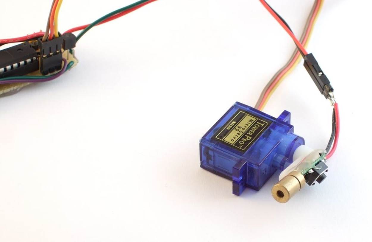
Figure 11-3. Directly mounted servo sundial
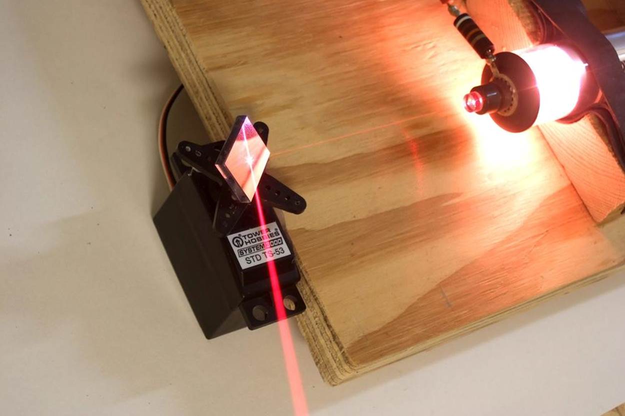
Figure 11-4. Helium-neon laser servo sundial
Try turning the servo through its full range, and figure out where on your ceiling or walls it points. Look around for a location with the widest possible angle that you can use to project the sundial on. If you’re lucky, you’ll be able to use nearly the servo’s full range for the sundial without shining the laser in your eye. And if you’re truly lucky, there will be the edge of a desk to hot-glue the servo to in just exactly the right spot. Add sticky notes to your ceiling to mark out the time, and you’ve got the setup in Figure 11-5.
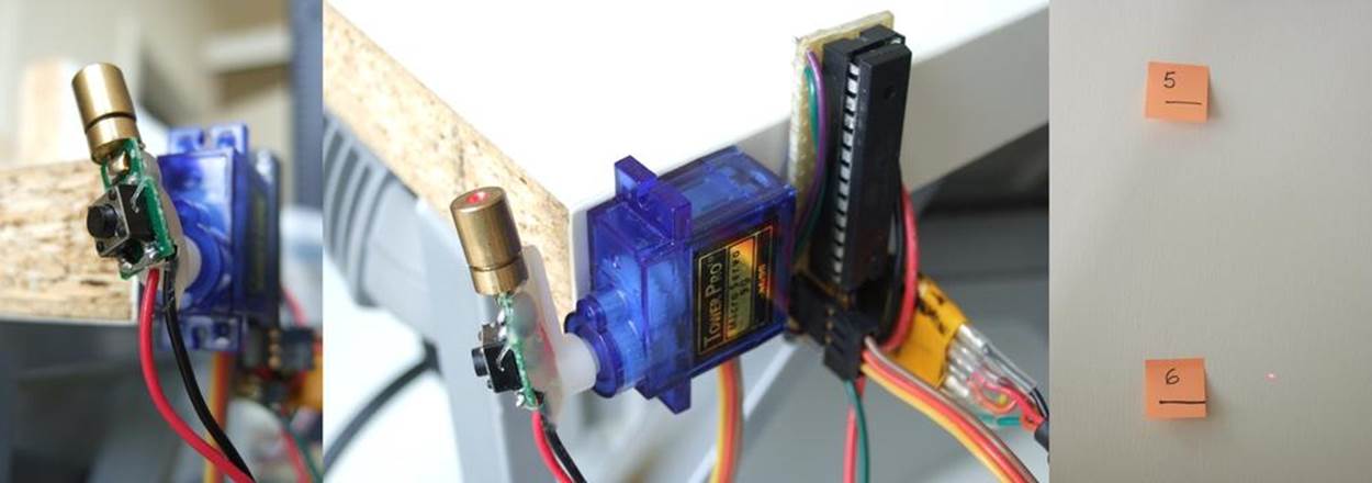
Figure 11-5. Laser servo sundial
Using the servo’s full range of motion allows you to tell the time more precisely. Remember from the servoWorkout.c demo that I figured out that my servo had about 600 usable positions once the width of the dead zone was taken into account? If you’re only using half of these, because you’re only using half of the servo’s total range of motion, you’ll have half of the possible time-resolution displayed on your wall.
The other tip to increase resolution is to limit the number of hours that the sweep of the “sundial” represents. If you’re only going to be in the office from 9 am to 5 pm, there’s no point in displaying times before or after that. If you can use the full servo range, and limit the sundial to displaying 10 hours (600 positions), it’ll easily get one-minute resolution.
But don’t sweat it too much. If you can locate the laser and servo someplace near to a power outlet (for plugging in a wall-wart to supply your clock with 5 V power) and the range is reasonable, go for it. Even if you’re only using half of the range and you need to display a whole day’s worth of time, you’ll be able to tell the time to the nearest five minutes, which is probably as good as any real sundial, right?
Once you get the software up and running, you can also fine-tune the position of some important times to match the joints in your wall or cracks on your ceiling. By setting the time over the serial port (or with the Python routine), you can test out where the beam falls at various times of the day, and tweak this to your liking. A final tip in this regard: don’t screw the servo horn in unless you need to. It’s convenient to be able to coarse-adjust the time-locations by pulling the whole attachment off and plugging it back in where you want it.
Or you can do what I did initially, and what our sun-using predecessors did, too, which is to take the position of the beam as granted and just mark off where the beam hits at different times of the day using sticky notes. With a laser sundial, you don’t have to correct for the seasons. And you don’t have to wait for a full day either; I’ve included a Python routine that steps the clock through the hours and that makes setting up your sticky notes a piece of cake.
My fantasy is to someday make light-sensitive alarm units (perhaps using the ADC and LDR setup of Chapter 7) and set alarms for myself by physically sticking them on the wall so that the light sensor is in the beam of the laser. When the time comes for the 10 am meeting, the laser hits the sensor, and an alarm is sounded, or a tweet is sent, or an email is dispatched. Rube Goldberg would be proud.
Ready the Lasers!
For this project, you’re not going to need a gigantic, multiwatt laser. In fact, the less bright it is, the better from both a power-usage and eye-hazard standpoint. And if you’re constantly wiggling the laser diode on the end of a motor, you’re not going to want to use anything valuable.
The standard red diode laser that comes in cat toys is perfect and only costs a few dollars, if you’re not lucky enough to have one around to scrounge. Most of these diodes come with circuitry that lets them run on three battery cells, or 4.5 V, which is close enough to just plug it straight into a 5 V power supply and hope for the best.
Whether or not you want to leave the laser in its decorative case is up to you. Originally, mine was in a mouse-shaped plastic case. Now I regret having extracted the laser unit, because who doesn’t want a servo-controlled laser mouse telling them the time? If you do want to pull out the laser unit, it’s as easy as shown in Figure 11-6.
The small “bullet” laser pointers that come in a thin metal casing can be removed only with brutality. I’ve gotten them loose using a pair of tin-snips and simply cutting through the case. (Do not use regular scissors.) Another option would be to simply buy a bare laser module. Online discount stores like DealExtreme have bare laser modules and cheap servos.
Many cheap laser pointers come with a switch that you’re supposed to press to turn the laser on. We’re going to need to take care of that. The easiest way to remove the switch from the circuit is just to solder across it. With a normal pushbutton switch, the two pairs of pins that are on the same side of the button connect to each other when pressed. Soldering a small wire across either pair will completely bypass the switch. You can see where I did this in the first frame of Figure 11-5.
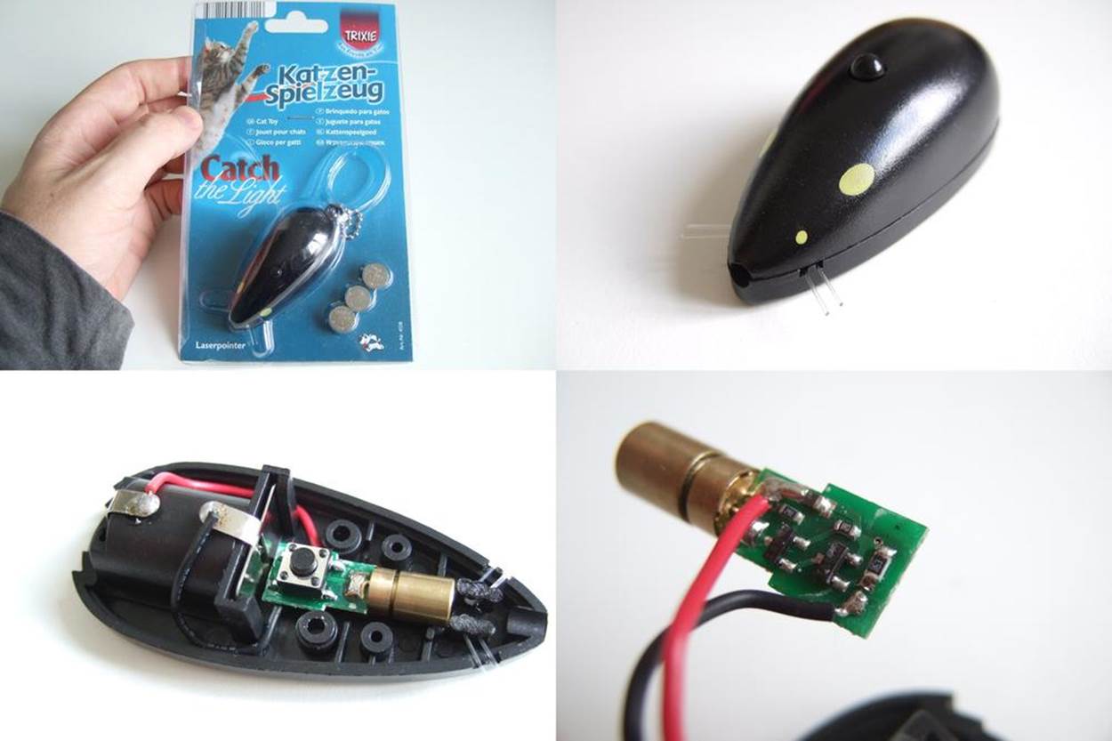
Figure 11-6. Getting the laser out
Now all you have to do is figure out how the AVR can turn the laser on and off. In Chapter 15, we’ll go over the use of transistor switches in great detail, so you can either look ahead at the description of using low-side MOSFET switches to control small loads, or you can just hook up the circuit in Figure 11-7.
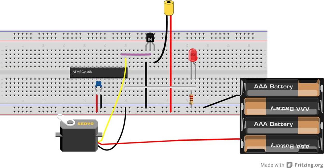
Figure 11-7. Breadboarding the laser sundial
The low-side switch consists of a 2N7000 MOSFET connected between the ground wire of the laser module and the circuit’s ground, so connect the ground wire from the laser to pin three of the 2N7000, and then connect pin one of the 2N7000 to our circuit ground. The AVR turns the 2N7000 switch on and off by changing the voltage on pin two of the 2N7000. Finally, because you can power the laser from your breadboard’s 5 V rail, simply plug that straight in.
The Code
The code to drive the servo sundial incorporates a bunch of snippets from code that we’ve seen before, and many of the parts will be familiar, but it’s a fair bit of code when it’s all put together. So to start, let’s sketch out the main sections.
We’ll use the 16-bit Timer 1 to drive the servo, and the 8-bit Timer 0 running as fast as possible to provide an accurate timebase for the clock. Because we’re mostly interested in displaying the minutes accurately, we’re really just keeping the seconds around to count up 60 of them. That is, we don’t really care when a second begins or ends as long as they all have the right length in time, and we can count them up. Because seconds aren’t tremendously timing-crucial to us, we’ll be handling all of the clock functions in themain loop.
The routine will also have to listen to the serial port, because that’s how we’ll be setting the time. In this case, because we’re going through the event loop rather quickly, we can also poll the serial port while we’re there. And finally, for fun and for debugging purposes, we’ll also be sending the time across the serial line every second.
So that’s the overview. This ends up being a large bunch of code, so I’ll break it up into a few files so that it’s more manageable. The main() routine is found in servoSundial.c, as are all of the functions to support using the servo. Definitions, function prototypes, and global variables are defined in servoSundial.h. Two more utility files are also included from within servoSundial.c: one for handling the serial I/O and another for the real-time clock functions. All four of these sections are covered separately here.
Main and the servo
Example 11-2 lists out the code for servoSundial.c.
Example 11-2. servoSundial.c listing
/* Quasi-realtime-clock with servo sundial. */
// ------- Includes -------- //
#include <avr/io.h>
#include <util/delay.h>
#include <avr/interrupt.h>
#include "pinDefines.h"
#include "USART.h"
#include "servoSundial.h"
#include "_servoSerialHelpers.c"
#include "_servoClockFunctions.c"
// -------- Functions --------- //
// Servo setup and utility functions
void initTimer1_Servo(void) {
/* Set up Timer1 (16bit) to give a pulse every 20ms */
TCCR1A |= (1 << WGM11); /* Using Fast PWM mode */
TCCR1B |= (1 << WGM12); /* counter max in ICR1 */
TCCR1B |= (1 << WGM13);
TCCR1B |= (1 << CS11); /* /8 prescaling -- microsecond steps */
TCCR1A |= (1 << COM1A1); /* set output on PB1 / OC1A for servo */
ICR1 = 20000; /* TOP value = 20ms */
}
void enableServo(void) {
while (TCNT1 < PULSE_OVER) {;
} /* delay until pulse part of cycle done */
SERVO_DDR |= (1 << SERVO); /* enable servo pulses */
}
void disableServo(void) {
while (TCNT1 < PULSE_OVER) {;
} /* delay until pulse part of cycle done */
SERVO_DDR &= ~(1 << SERVO); /* disable servo pulses */
}
void setServoPosition(void) {
uint32_t elapsedMinutes;
/* using 32 bits b/c elapsedMinutes * PULSE_RANGE will overflow 16 bits */
elapsedMinutes = (hours - START_TIME) * 60 + minutes;
OCR1A = PULSE_MIN + elapsedMinutes * PULSE_RANGE / (HOURS_RANGE * 60);
enableServo();
}
int main(void) {
// -------- Inits --------- //
initUSART();
printString("\r\nWelcome to the Servo Sundial.\r\n");
printString("Type S to set time.\r\n");
initTimer0_Clock();
initTimer1_Servo();
sei(); /* set enable interrupt bit */
LED_DDR |= (1 << LED0); /* blinky output */
LASER_DDR |= (1 << LASER); /* enable laser output */
// ------ Event loop ------ //
while (1) {
/* Poll clock routine */
if (ticks == OVERFLOWS_PER_SECOND) {
ticks = 0;
everySecond();
}
pollSerial();
} /* End event loop */
return (0); /* This line is never reached */
}
Just as before, we’re driving the servo using Timer 1, so the initialization for the servo-driving Timer 1 is almost the same as we used in Example 11-1. I probably cut and paste this same initialization routine every time I use a servo, and then tweak it to fit the particular application.
Up next are a few servo utility functions. When enabling and disabling servo control, it’s a good idea to make sure that we’re not doing so in the middle of a control pulse—this makes the motor glitch, often all the way down to the minimum end stop. BothenableServo() and disableServo() prevent this glitching by waiting for the Timer 1 counter to be past the longest possible pulse before changing the servo pin’s DDR.
setServoPosition() starts off by calculating how many minutes have elapsed since the turn-on time. To get the current control pulse length, we’d like to figure out how many microseconds of extra time to add per elapsed minute. That’s the point ofPULSE_RANGE/(HOURS_RANGE * 60) in the next line, but depending on your specific values, that’ll end up being a number like 1.6—which is unfortunately right in the middle of two small integers. If you round down to one, you’ll end up wasting around 30% of the servo’s range. If you round up to two, you run up against the servo’s endstop before the day is done. For maximum simplicity, you’d do the math using a floating-point math library. Using the AVR’s floating-point math library adds an extra 3.5 KB to your program’s size, and is generally not a good idea if you can avoid it. Although we’ve got the space for it here, I thought I’d take the opportunity to show you a workaround.
Rather than use floating-point numbers, we do all the multiplication and division in one line. That way, nothing gets rounded until the end of the calculation. The drawback, though, is that we risk an integer overflow during the calculation. For example, if your clock has been running 12 hours, that’s 720 minutes. If the difference between the minimum and maximum servo pulses is 1,000 microseconds, the quantity elapsedMinutes * PULSE_RANGE = 720 * 1,000 = 720,000, which is way too big to fit in a 16-bit integer. The solution is just to use a bigger integer type, so we define elapsedMinutes to be a 32-bit number. Now all of the calculations that involve elapsedMinutes, particularly the risky multiplication, will be done using 32-bit numbers, and we’ll get the right answer out. The code here takes less CPU time and less program memory than it would if we had used floating-point numbers, and we get the same answer!
Finally, moving down to main(), we call all the initialization functions, set up outputs, and enable interrupts. The event loop is a super-quick polling loop. If a second has passed, the clock-time handling functions are called via the everySecond() routine. Otherwise, the USART is checked to see if any data came in by calling the function pollSerial() that’s defined in the serial helper file.
Before we look into the real-time clock application section, let’s quickly get the header file out of the way.
The header
The header file’s contents are shown in Example 11-3.
Example 11-3. servoSundial.h listing
/* Quasi-realtime-clock with servo sundial. */
// ------- Includes -------- //
#include <avr/io.h>
// ------- Defines -------- //
#define PULSE_MIN 1000 /* experiment with these values */
#define PULSE_MAX 2000 /* to match your own servo */
#define PULSE_RANGE (PULSE_MAX - PULSE_MIN)
#define PULSE_OVER 3000 /* Must be larger than PULSE_MAX */
#define START_TIME 10 /* 10 am */
#define STOP_TIME 22 /* 10 pm */
#define HOURS_RANGE (STOP_TIME - START_TIME - 1)
#define LASER PB2
#define LASER_PORT PORTB
#define LASER_DDR DDRB
#define SERVO PB1
#define SERVO_PORT PORTB
#define SERVO_DDR DDRB
#define OVERFLOWS_PER_SECOND 31250 /* nominal, should calibrate */
// -------- Global Variables --------- //
volatile uint16_t ticks;
volatile uint8_t hours = 15; /* arbitrary default time */
volatile uint8_t minutes = 42;
volatile uint8_t seconds = 57;
// Serial input and output functions
void pollSerial(void);
void printTime(uint8_t hours, uint8_t minutes, uint8_t seconds);
// Servo setup and utility functions
void initTimer1_Servo(void);
void enableServo(void);
void disableServo(void);
void setServoPosition(void);
// Realtime-clock handling functions
// Use the globals ticks, hours, minutes, seconds
void initTimer0_Clock(void);
void everyHour(void);
void everyMinute(void);
void everySecond(void);
At the very top of the code are a bunch of defines that we’ll discuss in detail in Servo Sundial Calibration. Particularly, the OVERFLOWS_PER_SECOND variable will let us fine-tune the clock to get reasonably accurate seconds.
The other defines relate to the servo’s range of motion and the hours of the day that we’d like the device to run. You should be able to figure out the minimum and maximum for the servo pulse lengths from the servoWorkout.c demo code in the previous section.
Finally, before the function prototypes, the four global variables that make the real-time clock tick (tee-hee!) are defined. ticks will be incremented in an ISR, and the other variable names are fairly descriptive. The upshot of defining all of these time variables as global is that we can modify them from within the main() routine or any of the various subroutines that it calls.
The clock
Now let’s look at the clock code in Example 11-4.
Example 11-4. _servoClockFunctions.c listing
// Realtime-clock handling functions
void initTimer0_Clock(void) {
/* Normal mode, just used for the overflow interrupt */
TCCR0B |= (1 << CS00); /* 8 MHz clock = ~31250 overflows per second */
TIMSK0 |= (1 << TOIE0); /* timer overflow interrupt enable */
}
ISR(TIMER0_OVF_vect) {
/* This is going off very frequently, so we should make it speedy */
ticks++;
}
void everySecond(void) {
seconds++;
if (seconds > 59) {
seconds = 0;
everyMinute();
}
LED_PORT ^= (1 << LED0); /* blink */
printTime(hours, minutes, seconds); /* serial output */
/* Turn off servo motor after three seconds into new minute */
if (seconds == 3) {
disableServo();
}
}
void everyMinute(void) {
minutes++;
if (minutes > 59) {
minutes = 0;
everyHour();
}
// If during business hours, set servo to new minute
// Otherwise, don't need to move motor when laser is off
if ((hours >= START_TIME) && (hours < STOP_TIME)) {
setServoPosition();
enableServo();
LASER_PORT |= (1 << LASER); /* make sure laser is on */
}
else { /* make sure laser is off */
LASER_PORT &= ~(1 << LASER);
}
}
void everyHour(void) {
hours++;
if (hours > 23) { /* loop around at end of day */
hours = 0;
}
}
Between the timer initialization and the servo utility functions in servoSundial.c, we’ve got the servo sorted out. Global defines in servoSundial.h lay out the data skeleton for the clock. Now it’s time to get the clock up and running. Timer 0 and the associated ISR are the simplest possible clock timebase routine. The combination of the timer running at full speed, and overflowing every 256 steps yields a tick every 31,250th of a second (if the CPU clock runs exactly at 8 MHz).
If you look back at the event loop in main(), it continually checks the ticks variable to see when it hits our defined (and calibrated) OVERFLOWS_PER_SECOND value. When it does, it resets ticks and calls the routine everySecond(). This starts a cascade through the rest of the clock functions—just like the gears in a real mechanical clock.
The basic structure of each of the time-handling functions is the same. For instance, every second, the function increments the seconds variable and then checks to see if enough seconds have added up to warrant calling the everyMinute() function. Once that’s done, it handles the rest of the stuff that needs to happen every second. In this case, that’s blinking an LED, printing out the time over serial, and disabling the servo motor if it’s already been running for three seconds, to save energy.
The everyMinute() routine checks if it should increment the hours, then updates the servo position and turns on the laser if the time is within the device’s working hours. Finally, everyHour() increments the hours variable and wraps around to the start of a new day.
This code requires only a few global variables and a small bit of CPU overhead, but provides us with a tunable real-time clock with print-out functions over the serial port and alarm-clock like functions to boot. How can we beat that?
Serial I/O
Finally, wrapping up the firmware code are the two serial support functions in Example 11-5.
Example 11-5. _servoSerialHelpers.c listing
/* Functions for serial port output formatting and input */
void printTime(uint8_t hours, uint8_t minutes, uint8_t seconds) {
printByte(hours);
transmitByte(':');
printByte(minutes);
transmitByte(':');
printByte(seconds);
transmitByte('\r');
transmitByte('\n');
}
void pollSerial(void) {
/* Poll for serial input -- to set the time. */
char input;
if (bit_is_set(UCSR0A, RXC0)) {
input = UDR0;
if (input == 'S') { /* enter set-time mode */
printString("Setting time...\r\n");
printString("Hour: ");
hours = getNumber();
printString("\r\nMinutes: ");
minutes = getNumber();
printString("\r\nSeconds: ");
seconds = getNumber();
printString("\r\n");
ticks = 0;
if ((hours >= START_TIME) && (hours < STOP_TIME)) {
setServoPosition();
}
}
}
}
The printTime function is straightforward enough. As long as we don’t mind seeing leading zeros and reading the clock in 24-hour time, all we need to do is reuse our old favorite number-printing function from USART.c and spice it up with colons for punctuation.
If you recall the main event loop, it doesn’t really do much. It first checks to see if a second has elapsed and triggers the real-time clock functions if it has. Otherwise, it polls the serial line to see if anything has come in. If there has been data on the serial line, it enters the time-setting routine triggers if the character received is “S”, and otherwise just ignores anything that comes across the serial line.
The rest of the time-setting routine is implemented as prompt-input pairs until hours, minutes, and seconds have been entered. This interface isn’t very sexy, but it allows us (with good timing pressing Return) to get times into the sundial that are accurate down to the second. More importantly, for the calibration routines below, it’s very simple to script this time-setting procedure from a Python routine.
But for now, open up a serial terminal, type S and enter the current time in 24-hour time format, sit back, and relax. Maybe make marks, put up sticky notes, or even use some removable masking tape to plot out the time on the ceiling. If you’re impatient, you can short-circuit this procedure by typing in a time just before the one that you’re interested in setting, for instance 10:59:56. Now wait four seconds for 11 o’clock, and the servo will swing into place. Put your sticky note in place within the next minute, and repeat.
While you’re setting up the room to match the clock, you’ll probably notice that the servo isn’t exactly precise. The dead band is a lot easier to see when it’s magnified and projected on your ceiling. (In fact, if you’d like to reflash the servo workout routine, you can learn a lot more about the characteristics of your servo this way.)
In my office, the sundial only advances roughly every two or three minutes, and the direction that you approach the current time matters, too. To help with this, I wrote a small Python program, stepHours.py (included in the demo program’s directory), that slowly approaches each hour, and then stops for you to put up a sticky note and press Return before moving slowly on to the next one.
Servo Sundial Calibration
At this point, I do hope that you’ve got a little red dot creeping around your ceiling (or walls). It should provide you at least a few hours of accurate time-keeping as-is. But a few hours of accuracy is not enough! You want more. After all, you’ve put all this effort into hot-gluing a servo to the side of your desk, and taping sticky notes all over your ceiling. It’s probably worth a little bit of effort to see how accurate you can make the clock.
The reason behind the lousy accuracy is that the AVR’s internal CPU clock isn’t really meant for time-keeping. It’s meant to give you a quick-and-dirty clock pulse so that the chip can run without any external parts. The AVR datasheet suggests that this clock will be in the range of 7.3 to 8.1 MHz, which is nowhere near accurate enough. (If your chip is running at 7.3 MHz when you’re expecting 8 MHz, it will keep accurate time for about 12 minutes!) This is not to say that the AVR’s CPU clock will swing around across this wide frequency range—an individual chip’s CPU clock is pretty stable—but that if you pick a random chip out of a bucket, it could have a clock that runs fast or slow. Clearly, we’re going to have to fix this if our sundial clock is going to keep time.
The engineering (brute-force? proper?) solution to the problem is to use an external crystal instead of the internal clock source. After all, it’s easy enough to get a crystal that’s accurate to 20 parts per million, giving us a drift of around two seconds per day straight from the factory. Plug in a crystal, toss in a couple of capacitors, and then flash the AVR’s fuse bits to use the new clock source, and presto.
The hacker’s way is to take whatever we’ve got coming out of the chip and adjust our timebase to it. In particular, we’re counting up 31,250 overflows of the Timer 0 and calling that a second. But if your AVR’s internal clock is running fast, it may get 33,234 counts per true second. If we can figure out what this number should be, we’ll have a clock that’s accurate to roughly one part in 32,000, or 30 parts per million, which is almost as good as the crystal solution, and on the order of a few seconds per day.
As we saw earlier, the interface to the AVR’s clock routine was designed to be worked by humans. We type an “S” to enter time-setting mode, and then the hours, minutes, and seconds over the serial port to set it, and it echos the time back over serial every second. To calibrate your sundial, you could set the clock yourself, write down what time it is, and then come back in a while and see how much it has drifted. Then you’ll know how fast the clock is running, and you can just scale your counts-per-second define to match.
But doing that yourself is boring. Let’s whip up a quick Python routine that we can run on the computer to do the typing and dividing for us. Example 11-6 contains the code that I wrote up to do just that.
Example 11-6. calibrateTime.py listing
import time
import serial
def readTime(serialPort):
'''Reads the time from the AVR over the serial port'''
serialPort.flushInput()
character = ""
while(notcharacter == "\n"): # loop until see end of line
character = serialPort.read(1)
## The time string looks something like '011:045:023\r\n'
timeString = serialPort.read(13)
hms = timeString.split(":")
hms = [int(x) for x inhms] # make hour, minute, second numeric
return(hms)
def setTime(serialPort, hours, minutes, seconds):
'''Sends the time over the serial port'''
serialPort.flushOutput()
serialPort.write("S")
time.sleep(0.1) # delay while AVR sends
serialPort.write(str(hours) + "\r")
time.sleep(0.2) # delay while AVR sends
serialPort.write(str(minutes) + "\r")
time.sleep(0.2) # delay while AVR sends
serialPort.write(str(seconds) + "\r")
def setTimeNow(serialPort):
'''Sets the AVR clock to the current time'''
hours, minutes, seconds = time.localtime()[3:6]
setTime(serialPort, hours, minutes, seconds)
return(time.time())
def calculateTimeDelay(serialPort):
'''Gets AVR time and subtracts off actual (computer) time'''
avrHMS = readTime(serialPort)
hms = time.localtime()[3:6]
hmsDifference = [x - y for x,y inzip(avrHMS, hms)]
out = "AVR is fast by: {x[0]} hours, {x[1]} minutes, and {x[2]} seconds"
print out.format(x=hmsDifference)
return(hmsDifference)
def calculateTimeDrift(serialPort, startTime):
'''Calculates the ratio to multiply OVERFLOWS_PER_SECOND
given a start time and current error'''
h, m, s = calculateTimeDelay(serialPort)
driftSeconds = 60*60*h + 60*m + s
elapsed = time.time() - startTime
print "After {:.0f} seconds, ".format(elapsed)
return (driftSeconds / elapsed + 1)
if __name__ == "__main__":
## Set time automatically, recording start time,
## then periodically calculate multiplication factor
OVERFLOWS_PER_SECOND = 31250 # set this to equal the value in your code
SLEEP_TIME = 10
ratioLog = []
s = serial.Serial("/dev/ttyUSB0", 9600, timeout=5)
print "Setting time to current time...."
ratio = 0
while notratio == 1: # make sure starting time is right on
startTime = setTimeNow(s)
ratio = calculateTimeDrift(s, startTime)
## Note: you can either leave this running or
## you can re-run calculateTimeDrift() at any time in the future,
## as long as you don't overwrite the original startTime
while(True):
ratio = calculateTimeDrift(s, startTime)
ratioLog.append([time.time()-startTime, ratio])
newOverflow = int(OVERFLOWS_PER_SECOND * ratio)
print "OVERFLOWS_PER_SECOND should be {}\n\n".format(newOverflow)
time.sleep(SLEEP_TIME)
## As you leave this routine running, you should see it bounce
## around a lot in the beginning and then settle down after
## running a few hours. Ironically, it'll converge to a good
## number faster if it's initially very out of sync. (If it
## drifts faster, you can figure out the drift rate sooner.)
## Leave it running for 24 hours and you'll get one-second-per-day
## accuracy.
The Python code includes a bunch of helpful functions that you can use in your own code later on, and illustrates a couple of “tricks” that make interfacing over serial with the AVR easier. The first function, readTime(), takes input from an opened serial port and returns a list of the current hour, minute, and second. Because we’re outputting the time in “H:M:S” format from the AVR, we can split this string up on the colons, turn the values to integers, and return them. Done! Almost...
The first additional bit we’ll need to do is clear out all the old time messages that the AVR has been sending since we plugged it in. Your operating system has been (helpfully?) storing all of the data coming across the serial port in a buffer for you, which means when you start reading in all the data since you last read from the serial port. This is great when you don’t want to lose data in between reads, but it’s lousy when you simply want the freshest response, like we do here. The solution is to clear out the receive buffer first, and that’s what serialPort.flushInput() does. The code then reads in one character at a time until it sees the newline character (\n) that’s sent at the end of every line. Now we know that the next 13 characters to come across will be one time report.
The setTime() routine basically does what we’d do to set the time by hand. It sends an “S” over the line, pauses for a bit, and then sends the hours, minutes, and seconds data. The pausing is a bit of a kludge, in my opinion. What’s going on is that the AVR code echoes what we type back to us as we type it, and it uses the blocking transmitByte() routine for simplicity. Unfortunately, that causes the AVR’s serial port response to be a little slow, so the Python code compensates for that. It’s ugly. We could remove the echoing from the AVR’s code, and we wouldn’t need the delays in Python, but then we’d be typing blind. These delays are a compromise.
PYTHON MODULES
If you write code in Python that’s generally useful, you can include it in any of your other programs by simply including (“importing”) that module at the top of your code. Then all the functions defined in the imported module will be available under the name of that module.
This makes code reuse super easy. To create a software module, you can just save a bunch of functions in the same file, and import it later to use them. When you write another bit of code that needs one of the functions, just include the module file again. So if you define a function doStuff() in a file called myModule.py, you can later use it like this:
import myModule
## And use it
result = myModule.doStuff()
And this brings us to the code at the bottom of the module: if __name__ == "__main__":. This is a Python trick to make a file both able to run directly and be importable as a module. Basically, the code that follows the if __name__ == "__main__": statement will only be run if it’s the main program being run. If the file is imported from another file, the if statement is false, and the code at the bottom gets skipped. This way you can include code that you’d like to test out your module’s functionality when it’s called directly, but that you don’t have to load and run when it’s imported as a module. Neat, huh?
If we let this calibration routine run until it’s stationary, and use that result, we should get a clock that accurate to within a few seconds per day. Is this acceptable? Well, that’s a little more than a minute per month, and it’s probably better than the grandfather clock your parents had in the hallway. That should be good enough, right? I mean, the laser only moves perceptibly every couple minutes or so. But still, what if we want more? How accurate can we make this?
Suppose that, even though you’ve calibrated the seconds as precisely as you can, your sundial still runs fast by one second per day. As long as the clock is consistently fast by one second, you can fix this tiny drift up by adding in a leap second into your code, sometime while you’re sleeping. Just test the time with an if() statement in your code, and add a seconds++; whenever needed to keep the clock in line.
Adding leap seconds like this should make your clock accurate within a handful of seconds per week, and you should really stop here. The limits to how far you can push this exercise are most likely your patience and how stable you can keep the temperature in the room with the AVR—the AVR’s internal clock circuitry will run slightly faster as it gets warmer and slower when it gets colder. The AVR’s clock also speeds up a little bit as the supply voltage increases, so you’ll need to keep that precisely regulated as well. In the end, keeping super-accurate time is best left to government physics labs with large budgets.
And this realization leads us to the absolute best way to get a super-accurate AVR clock: get it from the Internet! If you’re able to connect to the Net, you’ll be able to sync your computer to a national standard clock to within one second. Now just write a Python script that sends the time to your AVR sundial once per day, and you’ll never be off by more than a few seconds. Even if you only resync once per month, your clock will be easily as accurate as its displayed resolution. Beats using the sun and shadows!
All materials on the site are licensed Creative Commons Attribution-Sharealike 3.0 Unported CC BY-SA 3.0 & GNU Free Documentation License (GFDL)
If you are the copyright holder of any material contained on our site and intend to remove it, please contact our site administrator for approval.
© 2016-2026 All site design rights belong to S.Y.A.