Make: AVR Programming (2014)
Part III. Advanced AVR Topics
Chapter 17. I2C
Logging Digital Thermometer
I2C is a tremendously popular protocol for interfacing microcontrollers with small sensors and these days even with devices that require more speed. Its main advantage is that you can talk to a large number of devices with just a couple of wires, which makes it much more like a network than the SPI bus. When you find yourself wanting to talk with I2C devices, this chapter will get you a head start!
We’ll be continuing on from Chapter 16 toward building a logging I2C thermometer. If you use the SPI EEPROM chip from last chapter, the logger will be capable of recording the temperature at a variable frequency for at least a few days on AA batteries. Then, when you want to read the data back out, the AVR code will dump it over the USB-Serial port back to your desktop computer for graphing and analysis.
And even if you don’t need a logging thermometer, you should be able to modify this code reasonably easily to work with other I2C devices. Indeed, I wrote most of the code in this chapter for a logging accelerometer that our hackerspace sent up into near-space with a helium balloon. There are I2C sensors available for almost any quantity you’d like to measure, all you have to do is look around.
WHAT YOU NEED
In addition to the basic kit, you will need:
§ An I2C device to talk to—my example uses the very common LM75 temperature sensor.
§ Two 10k ohm resistors to use as pull-ups for the I2C data line.
§ SPI EEPROM Memory chip from the previous chapter for logging data.
§ A USB-Serial adapter.
In the previous chapter, I extolled the main virtues of the SPI bus: it’s fast and simple. At least as long as you’re only communicating with a few devices. When you’re dealing with more than a few peripherals, the requirement to have one slave-select line per device on the network can get out of hand. (Imagine if the Internet worked like SPI! Each computer would need a physical wire to every other computer in the world just to tell the other that you’re ready to talk to it.)
Instead, we can give each device an address and require the master to send this address as a data prefix that the slave devices will listen for. That would drop SPI’s requirement of four wires (plus one more for each additional device) down to three.
And because most of the time we’re only sending meaningful data one way or the other, maybe we don’t need truly bidirectional, full-duplex communications like SPI provides. Maybe we could run everything half duplex, drop yet one more wire, and use only two? And if we could, we’d call the two wires by the more generic names “serial clock” and “serial data.” Hmmm….
Welcome to the beginnings of the I2C protocol. In contrast to SPI, it’s designed to use a minimum number of wires (two, plus ground) and yet handle a large network of devices (up to 128 with “standard” I2C). The trade-off is that I2C is a bit more complex from a user’s standpoint, and not capable of the same extreme speeds. However, when you need to connect your AVR to an LCD screen, a few buttons, some sensors, and a dozen networked multicolor blinky lights, I2C is the way to go. (Of course, nothing stops you from using both SPI and I2C peripherals at the same time—the AVR’s hardware peripherals are independent of each other.)
WHAT’S IN A NAME? (TWI, I2C, AND I2C)
“I2C” was once a trademark of Philips Electronics and is now owned by the spin-off IC company, NXP. While there’s absolutely no licensing issues surrounding using the “I2C” protocol, you’ll have to pay NXP money if you’d like to use the name “I2C” with your hardware.
Because of this, Atmel uses what they call a “Two-wire interface” (TWI) protocol that happens to be 100% compatible with “I2C,” but by calling it something else, they sidestep the trademark issue. So when you’re reading through Atmel documentation, feel free to read “I2C” anywhere you see “TWI.”
There are also a handful of “I2C"-like protocols, most of which are tiny variations (SMBus, PMBbus, etc.) or which are largely interoperable. So when I write “I2C,” I don’t mean “I2C,” but instead the whole family of “I2C"-like protocols that all work together. (And besides, typing superscripts all the time gets old.)
How I2C Works
Let’s start our discussion of I2C from the ground up. That is, we’ll start with some wires, then talk about the signals that run on the wires, and then finally the protocol that interprets these signals. The two wires that the I2C protocol uses are called SCL, for “serial clock,” and SDA, for “serial data.” The functions of these two lines won’t be particularly surprising.
Like SPI, I2C is a synchronous protocol, so there is a clock master that’s controlling the communication by sending out the timing signal. Unlike SPI, there’s a very strict convention about phase and polarity, thank goodness. With two exceptions, the I2C data line can change between high and low states only while the clock line is low, and data is to be read only while the clock line is high.
The two exceptions are made for the start and stop signals, respectively. A start signal is a falling edge while the clock line is held high, and a stop signal is a rising edge with the clock high. When the clock is low, anything can happen on the data line, but as soon as the clock line is pulled high, the only two allowed changes signal the beginning and end of a transmission, respectively. (See the timing diagram in Figure 17-1.)

Figure 17-1. I2C data timing
So an I2C conversation starts by pulling the SDA line low before the clock is started up. This is the start signal. Next, the master starts the clock with a low pulse. Data is then set up on the low clock phase and read out on the high clock phase until the transaction is over. In the end, the clock is stopped, and the master sends the stop signal by releasing the SDA line.
The I2C protocol doesn’t stop there, though. In order to allow multiple devices to share the same two lines, each slave device needs to know when it’s being spoken to. As hinted at earlier, this is done with an addressing scheme. In the original, and still most common, version of the I2C standard, each device has a specific seven-bit address, and every communication between the bus master and that device must start with the address.
But wait a minute…seven bits? The eighth bit is reserved for a read/write direction bit that determines whether the master or slave is going to send data over the data line next. A one/high-level direction bit means that the master expects to read data off the line, and a zero/low-level direction bit means that the master is going to write data to the SDA line.
So if the AVR sends a start, then the address of a slave device, and then a zero, the slave device knows that it’s going to receive a byte from the AVR (that is, the master is going to write a byte) immediately afterward. If the last bit after the address is a one, then the slave is responsible for sending data; the master reads data off the bus.
There’s one final complication that you need to know about. The device that’s receiving the data, whether it’s the master or slave, is responsible for acknowledging that it has received the byte. To do this, a ninth bit is sent after every 8-bit byte. A zero or low (“ACK”) indicates that the byte is acknowledged and signals that the sender should continue sending. A high bit (“NACK”) indicates that there was an error or that the transmitter should stop sending or that the whole communication is about to end, depending on the circumstances.
Note that the “ACK” or “NACK” bit is sent by the receiver rather than the transmitter. This makes it possible to detect if there’s been an error in the transmission, which can be handy if you’re operating in an electrically noisy environment. (And this is in contrast to SPI, where everything’s just assumed to work.)
Later on in this chapter, you’ll implement this exact conversation in code, but for now, to give you the flavor of a “complicated” I2C transaction between the AVR and an LM75 temperature sensor, let’s set the LM75 up for a temperature reading and get two bytes from it. To do this, the AVR will first need to send a byte to the LM75, to put it in temperature-reading mode, and then the AVR will need to receive two bytes (the temperature) from the LM75. The oscilloscope trace from this conversation can be seen in Figure 17-2.
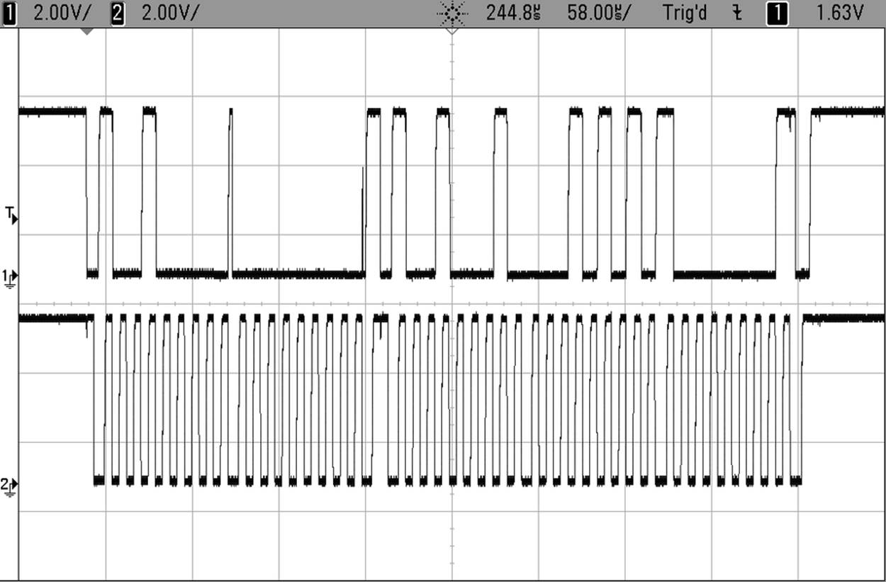
Figure 17-2. AVR talking I2C with LM75
To read the scope trace, it helps to keep three things in mind. First, I2C bytes are nine bits long—there’s always the ACK/NACK at the end. Second, if you look carefully at the clock line (the lower line), you can see how there are five slightly wider lows and one wide high. These occur at the start or end of every full byte. And finally, data is read out during the high clock period and changed during the lows. If you focus on the clock line, find a high, and then look up to the data line and read the value off, you can decode this. (You’ll notice that the LM75 is pretty quick about noticing a low clock and setting up its next bit as soon as it can.)
First, the AVR sends a start signal, changing the data line while the clock line is still high. Then the AVR sends the LM75’s address (1001000), followed by another zero to signal write mode, and the LM75 acknowledges. That thin upward spike in the scope trace during a clock low comes right after the slave’s ACK bit (the final zero) and the master picking up again to send the zero that starts off the next byte.
The second byte sent by the AVR is all zeros, which represents the temperature-register and tells the LM75 that a temperature read is coming next. The LM75 acknowledges again—a ninth zero. Now, because the AVR will be issuing a new command, the AVR briefly halts the clock signal while it’s high and sends another start command. That’s the downward transition in the data line during the long clock high period.
Next the AVR sends the address again, but this time followed by a one (10010001), indicating that the LM75 should speak. The LM75 acknowledges by holding the data line low, and then sends the most significant byte of data. In my office, it was apparently 21 degrees (00010101).
The AVR now acknowledges this byte with a zero, and the LM75 sends the least-significant byte, which in the case of the LM75 is the decimal place. For the cheap LM75s only the first bit counts, and it stands for half a degree. Here, the LM75 sent 10000000, so the full temperature reading is 21.5 degrees. Fancier LM75s can read down to the eighth of a Celsius degree, so there may be meaningful data in the first three of these bits.
And then finally, because it’s the end of the communication, the AVR sends a NACK (a one) and the stop signal by holding the clock line high and raising the data line.
I2C PROTOCOL SUMMARY
So to recap:
1. The SDA data line and SCL clock lines are both held normally high by pull-up resistors. Data is signalled as a zero by pulling the line low, or as a one by allowing the line to float back up high.
2. Communication starts with a start signal: pulling the data line low before the clock has started up.
3. Data is then set up during the clock low periods, and read out when the clock is high.
4. The first byte after a start is always the seven-bit address of the slave, followed by a direction bit indicating whether master or slave will be sending data on the SDA line next.
5. After each byte sent, the receiving device sends either an ACK bit (a low voltage, or zero) or a NACK bit (high, or one) depending on whether the communication is to continue.
6. If the master needs to change the direction of communication in the middle, it can send another start signal, followed by the address and new direction bit.
7. Finally, after the last transmitted byte, the master stops the clock and then releases the data line, sending a stop signal.
I2C WIRING
Both of these lines are normally held high when nobody is transmitting. In fact, electrically, the two I2C lines are held high by a pull-up resistor, and to send a zero on the data line, the devices connected to them pull the lines low with low-side transistor switches and just let the lines “float” back up to their high state.
A practical speed limit on how fast the I2C bus can run is how quickly this pull-up resistor can drag the whole wire back up to the high voltage level. For long I2C connections, the capacitance between the signal wires and ground can slow this transition down even further. If you’re having trouble with noise on a long (many inches) I2C line, that’s a good first place to start looking; try slowing down the data rate and see if that fixes the problem.
If you need the line to run faster, you can try to fine-tune the pull-up resistors on the line, but you may need to reroute the I2C lines to reduce inter-wire capacitance.
I2C Demo Hookup
It’s time to hook up the I2C thermometer to your breadboard. Don’t unplug the SPI EEPROM when adding in the LM75 temperature sensor chip, because we’re going to be using both together to make the temperature logger by the end of the chapter. With both peripherals on the breadboard, you should have something like Figure 17-3.
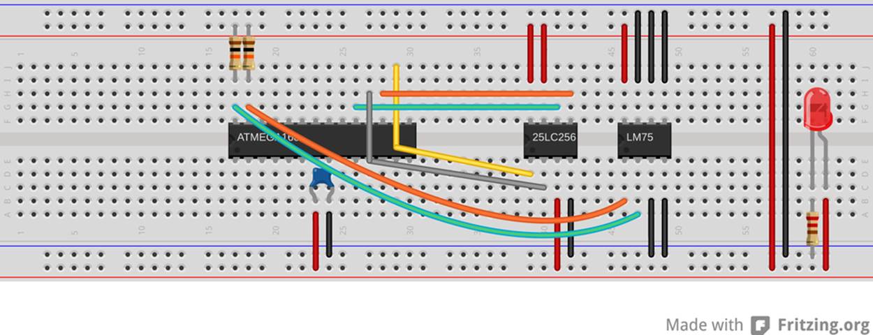
Figure 17-3. I2C/LM75 demo hookup
As with the 25LC256, the LM75 needs power and ground connected to its pins 8 and 4, respectively. In addition, the LM75 has three address pins that I’ve decided to set all to zero by grounding—they’re pins 5, 6, and 7 next to the VCC pin. Additionally, because I’m not using the external switch pin, pin 3, I ground it.
That leaves pins 1 and 2, SDA and SCL, which hook up to the AVR’s TWI pins, PC5/SDA and PC4/SCL. Last but not least, connect up the I2C protocol’s required pull-up resistors. They can be connected at either the AVR side or the LM75 side—whichever is convenient. That’s all that’s necessary for the circuit: basically two wires and two resistors. Too easy!
I2C Demo Library
If you just read my description of all that goes on in an I2C transaction, you’ll agree that it’s a lot of work to go through just to send a byte and get two back. (And if you read through the detailed description in the AVR datasheet, you’ll realize that I was giving you the short version!)
But because the protocol is so detailed, you can leave most of the details to hardware. The AVR’s “TWI” hardware, like the SPI and USART modules, has a register that is used to store data to be sent out across the I2C lines and stores the received byte after a successful receipt. All of the clocking and timing is taken care of by the AVR.
The TWI hardware helps you out with much more, however. If you’d like the AVR to act as an I2C slave, TWAR holds its address, and TWEA (“enable acknowledge”) automatically handles the generation of acknowledge bits when the AVR is receiving. There is an interrupt flag that signals, in slave mode, that the AVR is being addressed. The rest, you need to handle in your code.
If you want the AVR to behave as bus master, it needs to send start and stop signals, and you can send them by setting TWSTA and TWSTO bits, respectively. The AVR takes care of the timing, not sending its own start signal until after the line is clear. Then you send the address of the device you’re talking to, and then data, with or without acknowledge bits as configured.
If you thought I was a genius for being able to transmit the signal in Figure 17-2, you’ll be surprised how easy the AVR hardware makes it all. And for this demo, I basically just reused an old I2C library of mine that I had lying around, and frankly I encourage you to do the same whenever possible.
Because the AVR hardware takes care of so much of the low-level detail, the individual functions that read and write to the I2C bus are fairly straightforward and quite short. First, have a read through the header file in Example 17-1, and then we’ll dig into the code.
Example 17-1. i2c.h listing
// Functions for i2c communication
#include <avr/io.h>
#include "pinDefines.h"
void initI2C(void);
/* Sets pullups and initializes bus speed to 100kHz (at FCPU=8MHz) */
void i2cWaitForComplete(void);
/* Waits until the hardware sets the TWINT flag */
void i2cStart(void);
/* Sends a start condition (sets TWSTA) */
void i2cStop(void);
/* Sends a stop condition (sets TWSTO) */
void i2cSend(uint8_t data);
/* Loads data, sends it out, waiting for completion */
uint8_t i2cReadAck(void);
/* Read in from slave, sending ACK when done (sets TWEA) */
uint8_t i2cReadNoAck(void);
/* Read in from slave, sending NOACK when done (no TWEA) */
By now, you’re not surprised to see an initI2C function that sets up the necessaries for using hardware TWI. Because I’m not using interrupt-driven code, i2cWaitForComplete sits in a loop until an already-in-progress I2C byte is sent.
If you look back on the description of I2C in How I2C Works, you’ll see that we’re basically doing three things: sending data (and waiting for it to be acknowledged) or reading in data either with or without an acknowledge at the end. Of course, as the master, the AVR is also responsible for bracketing the conversation with start and stop conditions.
Let’s turn now to the i2c.c listing in Example 17-2. The actual code itself is not much longer than the words typed to describe it!
Example 17-2. i2c.c listing
#include "i2c.h"
void initI2C(void) {
TWBR = 32; /* set bit rate, see p. 242 */
/* 8MHz / (16+2*TWBR*1) ~= 100kHz */
TWCR |= (1 << TWEN); /* enable */
}
void i2cWaitForComplete(void) {
loop_until_bit_is_set(TWCR, TWINT);
}
void i2cStart(void) {
TWCR = (_BV(TWINT) | _BV(TWEN) | _BV(TWSTA));
i2cWaitForComplete();
}
void i2cStop(void) {
TWCR = (_BV(TWINT) | _BV(TWEN) | _BV(TWSTO));
}
uint8_t i2cReadAck(void) {
TWCR = (_BV(TWINT) | _BV(TWEN) | _BV(TWEA));
i2cWaitForComplete();
return (TWDR);
}
uint8_t i2cReadNoAck(void) {
TWCR = (_BV(TWINT) | _BV(TWEN));
i2cWaitForComplete();
return (TWDR);
}
void i2cSend(uint8_t data) {
TWDR = data;
TWCR = (_BV(TWINT) | _BV(TWEN)); /* init and enable */
i2cWaitForComplete();
}
Initialization is just a matter of configuring the SDA and SCL pins for output, selecting the bit rate, and hitting the enable button in the TWI configuration register, TWCR. If you want to run the I2C bus very slowly, that’s also fine, and there are also two prescaler bits in the TWI status register, TWSR, that you can use to divide the base rate by 1 (default), 4, 16, or 64.
I2C BUS SPEEDS
A word or two on the bit rate, while we’re here. The oldest I2C standard specified 100 kHz for the maximum bit-rate, and then came 400 kHz “Fast-mode” and 1 MHz “Fast-mode Plus” and recently 3.4 MHz “High-speed mode” and 5 MHz “Ultra Fast-mode.” My guess is that before the English language runs out of superlatives to go with “fast,” there will be a few more I2C speed grades as well.
In practical situations, the speed over the bus line is limited by how quickly the pull-up resistors can reraise the line’s voltage, and this in turn is limited by the intrinsic capacitance in the line. As you get up into higher and higher frequencies, the lines behave more like transmission lines than instantaneous signals, and you have to start worrying about termination and internal reflections and stuff like that.
If none of the above makes any sense, or it does and you just don’t feel like working these design issues into your circuit board, stick with the lower-speed 100 kHz or 400 kHz modes.
The function i2cWaitForComplete is the equivalent of the blocking-wait that we did in the UART code. When the byte in progress has been transferred across the I2C line, the TWINT flag is set. Here, we just loop until the transfer’s done. Unlike the UART code, where it can take a long time to get a byte in, especially if we’re waiting for a human to type it, here the wait is usually short enough that the cost of a blocking wait is not a problem.
The rest of the code simply gives readable names to the process of setting the bits we need to set in the TWI control register in order to send or receive data and includes the i2cWaitForComplete command where necessary. In particular, each of the other commands set the TWINT and TWEN bits, which has the effect of re-setting the interrupt flag and making sure that the TWI interface stays enabled. The additional bits in the TWCR that are either set or not determine the type of transaction: a start or stop signal; sending or receiving data; and with or without an ACK.
I2C ERROR CODES
If you wanted to be very careful about things, you could check up on the codes returned in the TWI status register after every transmission and make sure that there’s nothing strange going on. The AVR datasheet has five or six brutal pages going through all of the error codes and their causes. The util/twi.h standard library includes mnemonic macros for each of the I2C transaction status codes for your convenience.
Honestly, I’ve only had use for them once, and that was when I was trying to troubleshoot a problem that turned out to be of my own making—not sending a NACK at the end of a final byte caused the I2C data flash chip I was using to lock up every other conversation. You may get more out of the result codes than I did, however, so feel free to read through that section of the AVR datasheet when the time arises.
I2C Thermometer Demo
With I2C, just as with SPI, getting the AVR’s hardware to speak the protocol and shuttle data across is only half of the battle. The rest is in the specifics of communicating with a specific target chip. In the case here, it’s a cheap digital thermometer that sends the temperature over I2C. If you’d like to follow along as I work through the code in Example 17-3, go download the datasheet for your version of the LM75. (It’s a mostly standardized chip produced by multiple manufacturers, but with little difference across them. The datasheets should all be similar, too. For what it’s worth, I’ve looked at the ones from NXP and from National Semiconductor.)
Example 17-3. i2cThermometer.c listing
/* Reads LM75 Thermometer and Prints Value over Serial */
// ------- Preamble -------- //
#include <avr/io.h>
#include <util/delay.h>
#include <avr/power.h>
#include "pinDefines.h"
#include "USART.h"
#include "i2c.h"
// -------- Defines -------- //
#define LM75_ADDRESS_W 0b10010000
#define LM75_ADDRESS_R 0b10010001
#define LM75_TEMP_REGISTER 0b00000000
#define LM75_CONFIG_REGISTER 0b00000001
#define LM75_THYST_REGISTER 0b00000010
#define LM75_TOS_REGISTER 0b00000011
// -------- Functions --------- //
int main(void) {
uint8_t tempHighByte, tempLowByte;
// -------- Inits --------- //
clock_prescale_set(clock_div_1); /* 8MHz */
initUSART();
printString("\r\n==== i2c Thermometer ====\r\n");
initI2C();
// ------ Event loop ------ //
while (1) {
/* To set register, address LM75 in write mode */
i2cStart();
i2cSend(LM75_ADDRESS_W);
i2cSend(LM75_TEMP_REGISTER);
i2cStart(); /* restart, just send start again */
/* Setup and send address, with read bit */
i2cSend(LM75_ADDRESS_R);
/* Now receive two bytes of temperature */
tempHighByte = i2cReadAck();
tempLowByte = i2cReadNoAck();
i2cStop();
// Print it out nicely over serial for now...
printByte(tempHighByte);
if (tempLowByte & _BV(7)) {
printString(".5\r\n");
}
else {
printString(".0\r\n");
}
/* Once per second */
_delay_ms(1000);
} /* End event loop */
return (0); /* This line is never reached */
}
Find the section in the LM75 datasheet devoted to I2C, and we’ll work through the AVR code. The first thing I always do with I2C devices is create a definition for the slave’s 7-bit address with a zero and a one tacked on the end, so that I can remember which one is write mode and read mode.
Now if you read the datasheet, you’ll see that the last three bits of the address for a LM75 is “hardware programmable” by wiring up three pins of the chip to either VCC or GND where they take on values of one or zero, respectively.
I’ve wired up my LM75 with all three address pins to ground, so the address is 1001000. When we want to send data to the LM75, we’ll use 10010000 in the address field, and when we want to read data from the LM75, we’ll send 10010001, so I’ve definedLM75_ADDRESS_W and LM75_ADDRESS_R accordingly. I’ve also defined the four possible register pointer values from the datasheet, although we’ll only use one here. These allow you to set trigger temperature points in the LM75’s memory so that you can use it as a standalone thermostat or temperature controller, turning on an off an appliance when the temperature gets too hot or too cold.
Inside the event loop, the routine simply reads the temperature from the LM75, converts it from the two-byte format that it natively comes in, and transmits the value over the UART serial line. Let’s work quickly through the I2C communication section, though. To see why the code does what it does, have a look at the I2C timing diagrams located somewhere near halfway through the datasheet.
The LM75 comes in power-up default ready to read out its temperature data, but just so that we’re sure it’s giving us a temperature reading (and to demonstrate sending a restart signal), let’s set the temperature pointer just to be sure. Find the section in the LM75 datasheet where it describes something like “Read Temperature register including pointer byte (2-byte data)” or similar. Because the AVR hardware will take care of a bunch of the low-level detail for you, what you’re looking for in these diagrams are things like start and stop conditions, what bytes need to be sent in what order, and where ACK and NACKs are expected of the AVR when receiving data.
Communication with the thermometer starts off, naturally, with a start command. To set the pointer byte, we need to write to the LM75, so the AVR will send the LM75’s address plus the write flag and expect an ACK to be sure everything is OK. After the ACK, the AVR sends the temperature register command, which happens to be all zeros, and expects another ACK.
Now the AVR wants to read from the LM75, so it has to change the data direction. To do this, the AVR sends a restart and then the LM75’s address byte plus the read flag this time, and expects an ACK. Next, the LM75 should transmit a single byte, followed by an ACK, and then another byte, this time followed with a NACK to mark the end of the transmission. Finally, the AVR sends a stop signal to free up the I2C bus line for other communication. See how that translates fairly cleanly into code?
SPI and I2C Data Logger
Now let’s put all that we know about SPI and I2C together with a USART serial user interface. That’s right, three serial communication modes in one little project!
Combine an AVR, the EEPROM memory, and the LM75 thermometer and four AA batteries, and you’ve got a portable temperature logger that will run for days. And because the data is stored in the EEPROM, you can unplug the device at any time and pick up from wherever you left off. And when you connect it to your desktop computer’s serial port, you can dump all of the data and do whatever you’d like with it.
You should also note that, although this is a thermometer application, it could be anything. Data loggers are all very similar, and not particularly difficult to write once you’ve figured out how to communicate with the devices in question. For instance, if you wanted to build a GPS location-logger, you’ll be stoked to know that GPS modules almost all speak UART serial, and that parsing their report strings isn’t all that hard at all. Or maybe you’re interested in building a logging accelerometer. For instance, most accelerometers speak I2C and are even easier to integrate into a data logger. Heck, I don’t know what it is that you’re interested in logging, but here’s a simple framework to do it.
You’ve already seen the basics of how to work with both the SPI EEPROM and the I2C data from the LM75 temperature sensor. And because I wrote these functions into standalone libraries, reusing the functions is as easy as including the header files in the code and linking to their code in the makefile.
The main new bit in this project is a simple UART-serial based menu system that only activates if you type “m” within a few seconds of resetting the AVR chip. The goal was to build a device that’s both free-standing and can be controlled when plugged into your desktop computer. Implementing the menu is actually quite simple—you simply configure the serial port, wait for a few seconds, and then test if the desired character came across in the meantime. If yes, enter a menu loop that repeats until you type “s” to start logging. If “m” wasn’t received over the serial port during the delay time, jump straight into the event loop.
Let’s see how it all comes together in Example 17-4.
Example 17-4. loggingThermometer.c listing
// ------- Preamble -------- //
#include <avr/io.h>
#include <util/delay.h>
#include <avr/interrupt.h>
#include <avr/power.h>
#include "pinDefines.h"
#include "USART.h"
#include "i2c.h" /* for i2c functions */
#include "25LC256.h" /* for EEPROM specific */
// -------- Defines --------- //
#define LM75_ADDRESS_W 0b10010000
#define LM75_ADDRESS_R 0b10010001
#define LM75_TEMP_REGISTER 0b00000000
#define LM75_CONFIG_REGISTER 0b00000001
#define LM75_THYST_REGISTER 0b00000010
#define LM75_TOS_REGISTER 0b00000011
#define CURRENT_LOCATION_POINTER 0
/* where to store a pointer to the current reading in EEPROM */
#define SECONDS_POINTER 2
/* store seconds-delay value here */
#define MEMORY_START 4
/* where to start logging temperature values */
#define MENU_DELAY 5
/* seconds to wait before bypassing main menu */
// -------- Functions --------- //
static inline void printTemperature(uint8_t tempReading) {
/* temperature stored as 2x Celcius */
printByte((tempReading >> 1));
if (tempReading & 1) {
printString(".5\r\n");
}
else {
printString(".0\r\n");
}
}
int main(void) {
uint16_t secondsDelay; /* how long to wait between readings */
uint16_t currentMemoryLocation; /* where are we in EEPROM? */
uint16_t i; /* used to count memory locations */
uint8_t tempHighByte, tempLowByte, temperatureByte; /* from LM75 */
uint8_t enterMenu; /* logical flag */
// -------- Inits --------- //
clock_prescale_set(clock_div_1); /* 8 MHz */
initSPI();
initI2C();
initUSART();
LED_DDR |= (1 << LED0);
/* Load up last values from EEPROM */
secondsDelay = EEPROM_readWord(SECONDS_POINTER);
/* Delay to allow input to enter main menu */
printString("*** Press [m] within ");
printByte(MENU_DELAY);
printString(" seconds to enter menu. ***\r\n ");
for (i = 0; i < MENU_DELAY; i++) {
_delay_ms(1000);
}
if (bit_is_set(UCSR0A, RXC0) && (UDR0 == 'm')) {
enterMenu = 1;
}
else {
enterMenu = 0;
}
while (enterMenu) {
printString("\r\n====[ Logging Thermometer ]====\r\n ");
currentMemoryLocation = EEPROM_readWord(CURRENT_LOCATION_POINTER);
printWord(currentMemoryLocation - MEMORY_START);
printString(" readings in log.\r\n ");
printWord(secondsDelay);
printString(" seconds between readings.\r\n");
printString(" [<] to shorten sample delay time\r\n");
printString(" [>] to increase sample delay time\r\n");
printString(" [?] to reset delay time to 60 sec\r\n");
printString(" [d] to print out log over serial\r\n");
printString(" [e] to erase memory\r\n");
printString(" [s] to start logging\r\n\r\n");
switch (receiveByte()) {
case 'd':
SLAVE_SELECT;
SPI_tradeByte(EEPROM_READ);
EEPROM_send16BitAddress(MEMORY_START);
for (i = MEMORY_START; i < currentMemoryLocation; i++) {
SPI_tradeByte(0);
printTemperature(SPDR);
}
SLAVE_DESELECT;
break;
case '<':
if (secondsDelay >= 10) {
secondsDelay -= 5;
EEPROM_writeWord(SECONDS_POINTER, secondsDelay);
}
break;
case '>':
if (secondsDelay < 65000) {
secondsDelay += 5;
EEPROM_writeWord(SECONDS_POINTER, secondsDelay);
}
break;
case '?':
secondsDelay = 60;
EEPROM_writeWord(SECONDS_POINTER, secondsDelay);
break;
case 'e':
printString("Clearing EEPROM, this could take a few seconds.\r\n");
EEPROM_clearAll();
EEPROM_writeWord(CURRENT_LOCATION_POINTER, MEMORY_START);
EEPROM_writeWord(SECONDS_POINTER, secondsDelay);
break;
case 's':
printString("OK, logging...\r\n");
enterMenu = 0;
break;
default:
printString("Sorry, didn't understand that.\r\n");
}
}
// ------ Event loop ------ //
while (1) {
currentMemoryLocation = EEPROM_readWord(CURRENT_LOCATION_POINTER);
/* Make sure in temperature mode */
i2cStart();
i2cSend(LM75_ADDRESS_W);
i2cSend(LM75_TEMP_REGISTER);
/* Get Temp from thermometer */
i2cStart(); /* Setup and send address, with read bit */
i2cSend(LM75_ADDRESS_R);
tempHighByte = i2cReadAck(); /* two bytes of temperature */
tempLowByte = i2cReadNoAck();
i2cStop();
temperatureByte = (tempHighByte << 1) | (tempLowByte >> 7);
/* temperatureByte now contains 2x the temperature in Celcius */
printTemperature(temperatureByte); /* serial output */
/* Save the new temperature value */
EEPROM_writeByte(currentMemoryLocation, temperatureByte);
/* move on to next location and record new position
if not already at the end of memory */
if (currentMemoryLocation < EEPROM_BYTES_MAX) {
currentMemoryLocation++;
EEPROM_writeWord(CURRENT_LOCATION_POINTER, currentMemoryLocation);
}
/* delay */
for (i = 0; i < secondsDelay; i++) {
_delay_ms(1000);
LED_PORT ^= (1 << LED0); /* blink to show working */
}
} /* End event loop */
return (0); /* This line is never reached */
}
Pointers in EEPROM
First off, I just copied the definitions for the LM75’s I2C address into the top of the code to make reading and writing just as easy as it was in the demo program. What follows next, though, is a little bit interesting. I define three EEPROM memory locations.
The first defined memory location is the one in which I plan to store the memory location where the current temperature reading should go. (If you’ve never been through pointers in C, reread that sentence until it makes sense.) The idea is that if the AVR is reset, we don’t want to start writing again at the beginning of memory, because then we’d overwrite whatever data we have in memory. So instead, we keep track of where we should be writing next. But we can’t keep track of it in RAM, because we lose that when the battery goes dead, so we write the current EEPROM memory location itself into EEPROM. CURRENT_LOCATION_POINTER is the memory location where the current memory location value is stored.
Next, I wanted the device to be menu-configurable in terms of how many seconds to sleep between data readings, rather than have the value hardcoded into a #define or something. But this also means that whatever value is last decided on needs to be stored somewhere nonvolatile—on our SPI EEPROM. SECONDS_LOCATION is the location in EEPROM where the number of seconds per update is stored.
Jumping briefly down to the main() body, you can see that just after the various serial initialization functions are called, the code initializes a variable secondsDelay from the EEPROM location defined earlier. Because the code uses this value frequently, it’s probably worthwhile to keep it in RAM like this. If RAM is tight, though, you could simply reread the value from EEPROM every time you needed it.
CONFIGURATION PARAMETERS AND INTERNAL EEPROM
Storing nonvolatile configuration parameters like this is very common in small embeddded devices, and to help with that, the AVRs actually have a very small amount of built-in EEPROM so that you can do the same trick as here, but without needing external memory.
Unfortunately, internal EEPROM is measured in bytes rather than kilobytes, so it’s not very good for data-logging purposes, but we’ll see in Chapter 18 how to use internal EEPROM to store configuration parameters and other user data.
Both of the memory pointer and the delay value are 16-bit numbers, so note that I’m allocating two bytes for each in choosing the locations. Finally, MEMORY_START is a useful definition to have around. This way, we’ll know where to start recording again after a complete memory erase.
The UART Serial Menu
We saw a simple UART-serial menu system in a few examples so far. This one’s the most elaborate. In this menu, there are options for setting the delay, printing out all the data from the EEPROM over the serial line, erasing the SPI EEPROM, and simply leaving the menu and entering logging mode. First, let’s talk about how to get into menu mode, and then we’ll look at the menu code itself.
When the chip first wakes up from a reset, it prompts over the UART serial line to to press “m” within a few seconds to enter the menu. This is followed by a completely normal delay, and then the serial receive flag is checked. If anything came through, it’s checked to be equal to “m” or not. If it is, a flag variable, enterMenu, is set, and otherwise, not.
Now the menu loop can easily be constructed as a while(enterMenu) loop around a switch() statement that reads from the serial input, so that any of the commands in the menu can be run, and as long as they don’t change the value of enterMenu, we loop around for the next command. Then, if the serial input “s” is received, the enterMenu variable is set to zero and the while() is no longer true, and execution moves on to the event loop.
This pattern of a while() loop with a switch() inside, where one or more of the options invalidate the while(), is a common pattern for things like menus and multiple-choice routines.
From the perspective of this chapter, the other interesting detail in the menu section is the way that dumping all of the logged memory is handled. Here, we use the feature of the EEPROM that it will continue spitting out its memory contents one at a time as long as it receives an SPI clock. Because the last-stored memory location is in the variable currentMemoryLocation, we can run through all of the logged memory by starting at the defined MEMORY_START and reading out currentMemoryLocation-MEMORY_START values and printing them out over the UART serial port.
Accessing all of the logged EEPROM memory in one SPI transaction like this is by far the fastest way to dump all of the EEPROM, but it won’t actually have any real effect on overall speed, because the SPI bus is so much faster than the UART printout. Oh well.
The Logger’s Event Loop
Finally, whether the user has hit “s” to escape from the menu loop or never entered the menu to begin with, we enter the event loop, and the next chunk of code sets the LM75 temperature pointer and reads out the temperature just as we did in the temperature sensor demo.
The nine-bit temperature value is trimmed down to eight bits so that it fits more easily in memory, the memory location is updated if it’s still within the range of the EEPROM’s maximum number of bytes, and the data is stored. The memory address pointer in EEPROM is then updated and the AVR delays.
In my personal version of this code, I also added in a slow timer to provide a system tick so that you can put the AVR and LM75 to sleep, using the timer and an interrupt to wake everything back up. Dig into the LM75’s sleep mode in its datasheet if you’re interested. With both the AVR and the LM75 asleep (and the EEPROM drawing no power), the power drain is less than a battery’s self-discharge rate. If you only take a temperature reading once every fifteen minutes, you could leave it running for a year! Not bad for around $5 in parts.
All materials on the site are licensed Creative Commons Attribution-Sharealike 3.0 Unported CC BY-SA 3.0 & GNU Free Documentation License (GFDL)
If you are the copyright holder of any material contained on our site and intend to remove it, please contact our site administrator for approval.
© 2016-2026 All site design rights belong to S.Y.A.