Make: More Electronics (2014)
Chapter 22. Experiment 22: Logically Audible
In this experiment I want to take a break from logic problems and probability. I’m going to show you how to build something that is fun, weird, and simple (although later in the book, I’m going to find a way to make it more complicated). I’m going to show you how to pass audio signals through logic chips.
Background: Neither Here nor Theremin
Long ago, in the earliest days of electronics, a gadget called a theremin created creepy noises on the sound tracks of horror movies. The theremin (pronounced “ther-a-min”) was played in real time by a performer who waved his or her hands around two rods that were sensitive to fluctuations in capacitance between the theremin and ground. A skilled operator could make a theremin play recognizable melodies, although it sounded a bit like a violin bow moving to and fro across a tensioned hand saw.
Search online, and you’ll find a complete explanation of how the theremin worked. You can even find MP3s of theremin performances, and a component kit that you can buy to build a theremin of your own.
When you used a phototransistor to control the frequency of a timer in Experiment 3, you created results that sounded a bit like a theremin. Now that you have become well acquainted with logic chips, you can use that knowledge to combine two (or more) audio frequencies, like a super-theremin.
Logical Audio
You might think a logic chip is totally inappropriate in an audio circuit, but bear in mind three factors:
1. Audio frequencies of 20Hz to 15KHz are slow, from the point of view of a chip that is designed to handle frequencies above 1MHz.
2. The square waves produced by a timer will never sound as mellow and melodious as a sine wave, but they are certainly audible.
3. Conventional music is already digital. Almost all the music you listen to, from CDs to MP3s, is created and processed with digital sampling.
Audible XOR
In Figure 22-1 you’ll see a circuit that is somewhat similar to the one in Figure 5-1. The big difference is that the timer outputs are now linked by an XOR gate, and the output from the XOR goes through a transistor to a loudspeaker. Yes, this is a highly unusual arrangement, but all the components are operating within their specifications, and I think the results are interesting.
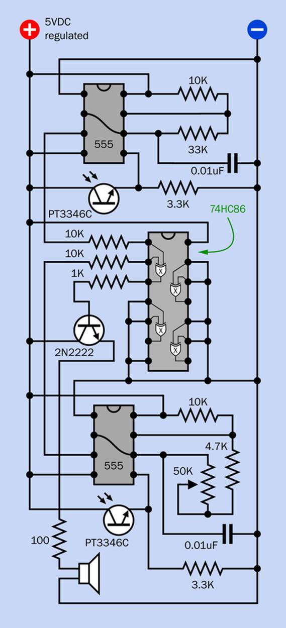
Figure 22-1. Schematic for a circuit that XORs the audible frequencies from two timers.
It shouldn’t take you long to put these components together. Figure 22-2 shows my breadboarded version.
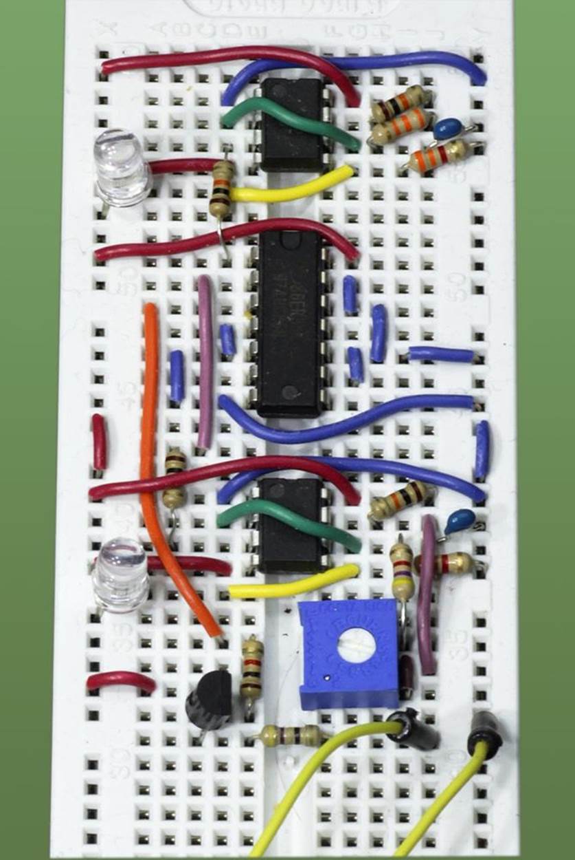
Figure 22-2. The breadboarded version of the previous schematic.
If you haven’t made any wiring errors, you should get all kinds of sounds when you vary the light on the phototransistors while adjusting the 50K trimmer up and down. What’s going on here?
All Mixed Up
Remember how an XOR gate works. Its output is only high when one of its inputs is high but not the other. Therefore, when you’re feeding two audio signals into it, the output from the XOR is high when the signals are out of phase, but it transitions low when the signals are in phase.
Figure 22-3 shows this graphically, with an XOR and also with an AND and an OR gate. The pinouts of the 74HC08 quad two-input AND chip, the 74HC32 quad two-input OR chip, and the 74HC86 quad two-input XOR chip are all the same, so you don’t need to change the wiring of your circuit to hear the different effects when you swap chips in and out.
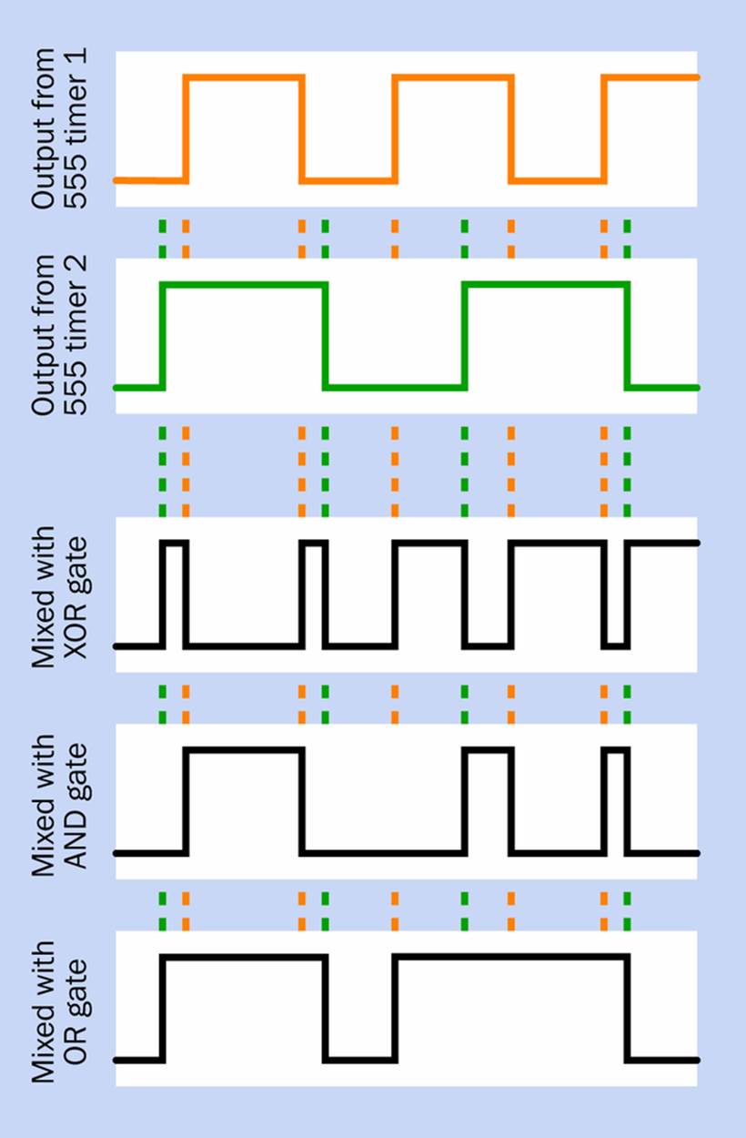
Figure 22-3. As the highs and lows of two audio frequencies overlap, different logic gates will create contrasting audio effects.
The OR gate gives an output when either of the timers emits a pulse, while the AND gate is fussier, only responding when both of the timers have high signals. I think the XOR gate is the most interesting, which is why I suggested you should try it first.
You can easily imagine more options. For example, you could substitute a second 50K trimmer for the 33K resistor—but put a 4.7K resistor in series with it to avoid a situation where you may end up applying zero resistance to Pin 6 of the timer when you turn the trimmer all the way down. This would be tough for even a robust 555 timer to endure.
You can increase the value of R1 relative to the value of R2 in one or both of the 555 circuits to lengthen the high cycle relative to the low cycle. This may sound good with the XOR gate, which tends to chop the cycles into smaller pieces. For instance, what happens when you substitute a 470K resistor for the 33K resistor? What happens if you substitute a 1M or even higher resistor for the 33K resistor?
When the first timer is running much more slowly than the second, you can really hear their frequencies interacting. With the 1M resistor in place, substitute a 0.1µF capacitor for the 0.01µF capacitor on the first timer. This creates a fluctuating two-tone effect. If you sketch the two outputs from the 555 timers, you should be able to see why.
Can you think of any applications for this circuit? Perhaps it could be the voice of a robot, changing as the robot moves around and exposes the phototransistors to different light patterns. Angle the phototransistors in different directions to heighten the effect. Or you could remove the phototransistors and simply adjust the trimmer to find the optimum sound that you want to use for an audible response in any other electronics project.
What if you created a duplicate of this entire circuit, and then XORed the two XOR outputs? I’m going to leave you to explore possibilities of that kind.
There’s an ulterior motive behind this experiment. I’m going to use the concept in Experiment 26 for a totally different purpose: creating random bursts of visible pulses.
All materials on the site are licensed Creative Commons Attribution-Sharealike 3.0 Unported CC BY-SA 3.0 & GNU Free Documentation License (GFDL)
If you are the copyright holder of any material contained on our site and intend to remove it, please contact our site administrator for approval.
© 2016-2026 All site design rights belong to S.Y.A.