Make: More Electronics (2014)
Chapter 23. Experiment 23: A Puzzling Project
Here’s another relatively simple experiment with logic, enabling a two-player game that seems deceptively easy—until you play it yourself. Like the Hot Slot game, I’m going to come back to it later in the book. In Experiment 32, I’ll suggest ways to upgrade the user input when I start to explore the world of sensors. For the time being, though, the game will be playable with pushbutton switches.
Background: The British King of Puzzles
Before the advent of television—before there was even radio!—British newspapers used to entertain their readers with little games and puzzles. These were much more challenging than today’s crossword puzzles.
King of the British puzzle-makers was Henry Ernest Dudeney, a master of the art of asking a question in just one paragraph that could require days or weeks for anyone to answer.
Many of his problems were geometrical or arithmetical. For instance, he challenged readers to find the two prime factors of the number 11,111,111,111,111,111—and somehow, using only pencil and paper, Dudeney was able to supply the right answer. (Even using a computer, this is not a trivial problem, because the numbers are so large.)
He had a playful streak, as in this cunning little puzzle:
§ A customer wants a builder to make a window measuring two feet on each side. The window must be divided into eight panes. Each pane must measure one foot on each side. There must be no empty spaces. This sounds impossible, yet it can be done. The question is, how?
For the answer to the window problem, see Answer to the Puzzle—but first, try to figure it out for yourself. A hint: the secret is in the way the question is worded.
Moving Counters
Dudeney enjoyed what he called moving-counter problems. Checkers is an obvious one, because counters move around the board until one person wins. Tic-tac-toe is not a moving-counter problem, because the marks remain fixed on a piece of paper—but it can become a moving-counter problem and is much more interesting as a result. In this mode, Dudeney referred to it as “Ovid’s Game,” because he claimed to have found it mentioned in the works of the Roman poet Ovid. That may or may not have been true, but in any event, while the strategy is subtle, the rules are very simple:
§ The game is for two players, each of whom has three counters. The counters for one player are different in color from the counters for the other player.
§ The playing board consists of nine square cells, like a tic-tac-toe grid.
§ Players take turns placing their counters one at a time, anywhere on the grid.
§ After each player has placed three counters, the players take turns moving their counters. A move consists of shifting one counter into an empty adjacent empty cell. Diagonal moves are not allowed.
§ A player wins by getting three counters in a row, horizontally, vertically, or diagonally.
§ Because the center cell is important in this game, the first player is not allowed to place a counter in the center on the first turn.
The key to this game is to place your counters to obstruct your opponent. Remember, although you can shuffle your counters around, you are not allowed to jump over your opponent’s counters, and you can only move one square at a time.
For example, in Figure 23-1, if it’s white’s turn to move, he should shift from square 6 to square 5, to obstruct black’s two counters. Now black has no way to prevent white from winning on the next turn by playing from square 3 to square 6. Game over!
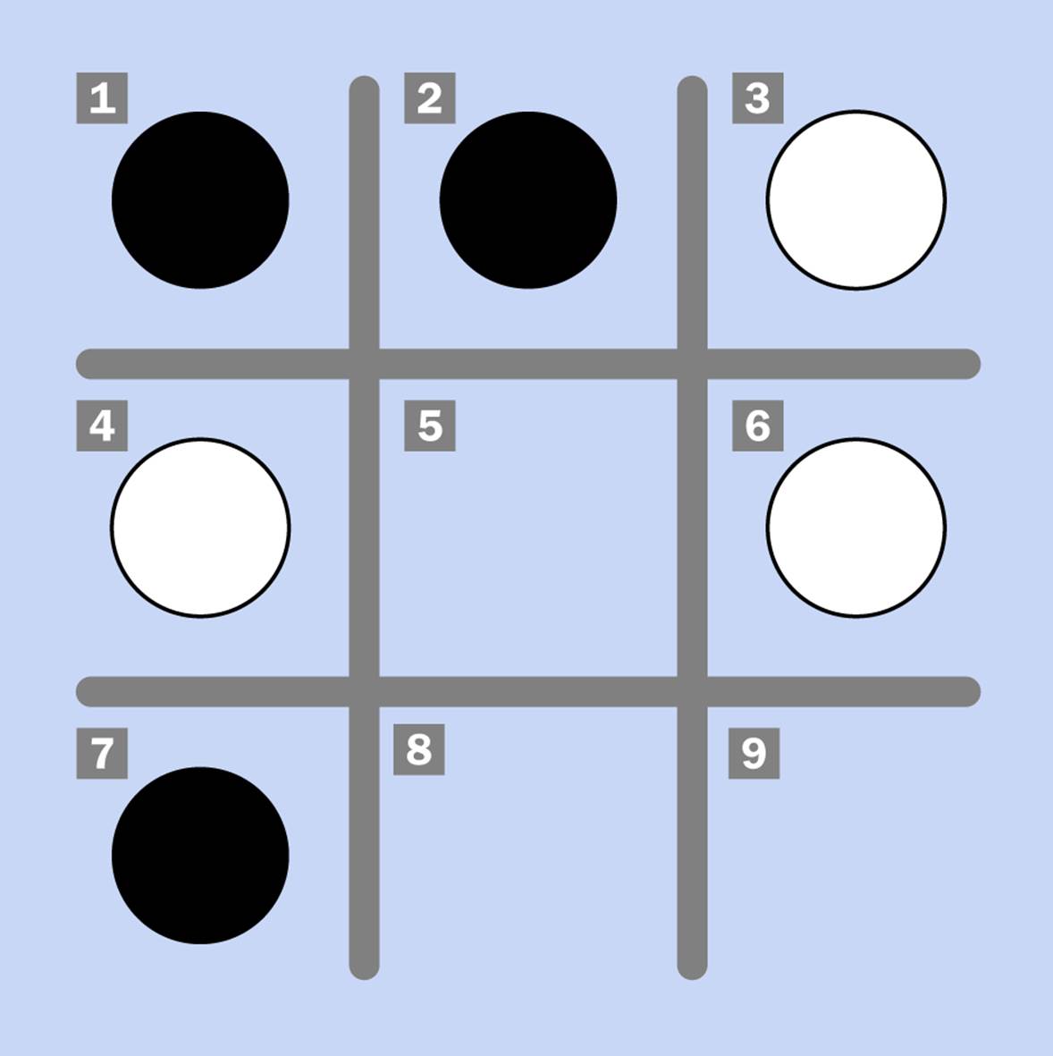
Figure 23-1. A hypothetical situation in Ovid’s Game.
But let’s suppose that it’s black’s move. In that case, she should move from 2 to 5 to prevent white from occupying that square. After that, the outcome of the game is hard to predict.
I don’t know how to build a circuit that’s smart enough to play this game, but I can show you a circuit that will detect if someone has won it. The same circuit will also respond if someone gets three in a row in a tic-tac-toe game, although I’m assuming that tic-tac-toe is too simple to interest most of my readers.
You may feel that a circuit that detects a winning combination is unnecessary, because anyone can see if there are three counters in a row. Well, yes, of course! But it’s fun to have an audible signal when you win, and a circuit that can detect this will rouse some curiosity. Just how does it work?
The Logical Grid
The first question we have to decide is how to process user input. That is, how can an electronic circuit detect if someone makes a move? The simplest answer is to get rid of the two colors of counters and substitute two kinds of switches (one for each player) in each cell on the board. At the start of a game, players take turns to flip switches until each person has activated three switches. After that, a move consists of turning off one switch and turning on a switch in an adjacent empty cell. Of course you’re not allowed to flip a switch in a cell that is already occupied by your opponent.
Latching pushbuttons (the type that you press once to turn on and a second time to turn off) seem ideal for this task. If there is a colored LED beside each button (perhaps red for one player and blue for the other), it will be easy to see who is occupying a square. InFigure 23-2 I’m including a rendering to show you what I have in mind.
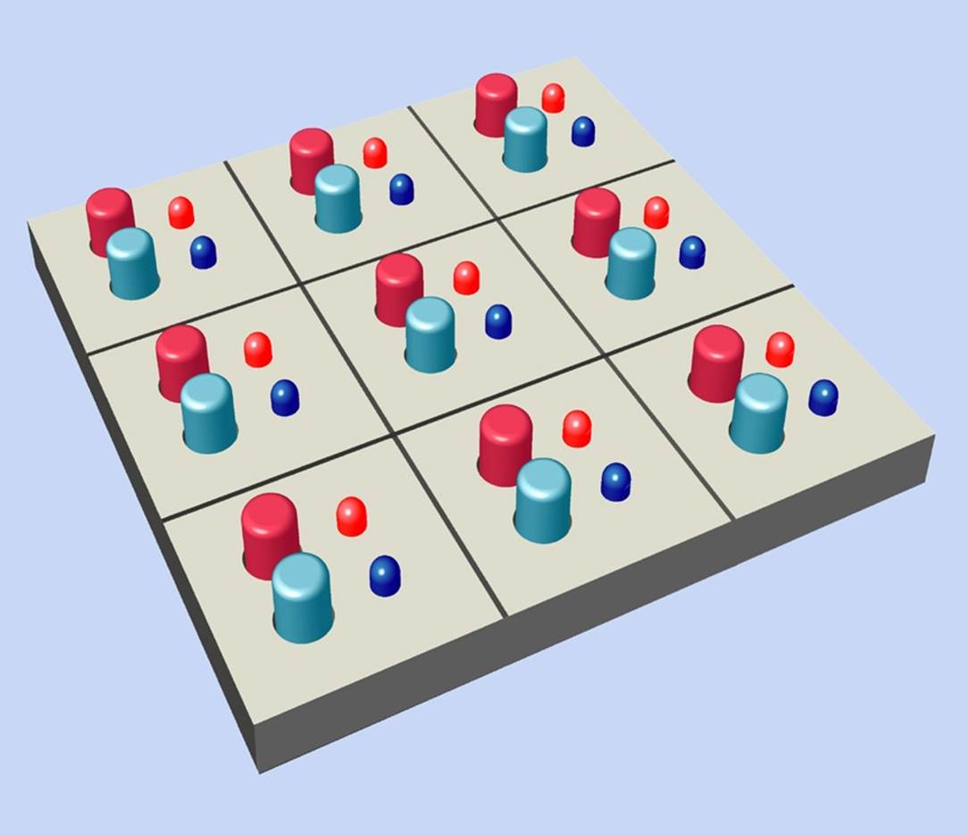
Figure 23-2. The simplest way to provide user input for electronics in Ovid’s Game is to have latching pushbuttons and LEDs for each player.
Another option would be to use ON-OFF-ON switches—that is, a three-position switch with a center-off position. Each player occupies a cell by turning the switch toward him, and the cell is vacated when the switch is returned to its center-off position. You can buy ON-OFF-ON single-pole switches very cheaply, and because each one has two “on” positions, you’ll only need nine instead of the eighteen latching pushbuttons.
Using Logic
Suppose we use logic gates to detect a winning move. In that case, as usual, I will begin by describing the logic in words. If the squares are numbered 1 through 9 as shown in Figure 23-1, I can state the problem like this:
The winning player must occupy cells 1 AND 2 AND 3, OR 4 AND 5 AND 6, OR 7 AND 8 AND 9, OR 1 AND 4 AND 7, OR 2 AND 5 AND 8, OR 3 AND 6 AND 9, OR 1 AND 5 AND 9, OR 3 AND 5 AND 7.
If you have been reading this book sequentially, you’ve had a lot of practice in converting this kind of sentence into an array of logic gates. You can see there are eight possible winning combinations, linked with ORs, and each combination consists of three conditions linked with ANDs. Can you draw a logic diagram? The basic concept is shown in Figure 23-3, while a complete diagram, including the switches, is shown in Figure 23-4.
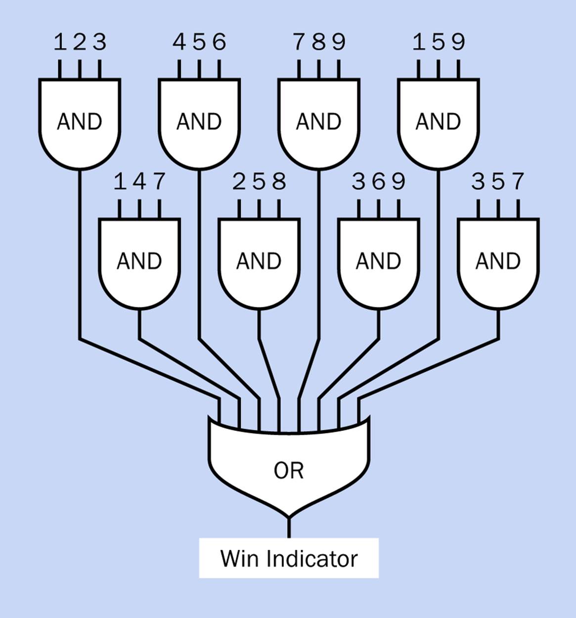
Figure 23-3. The bare bones of a logic diagram for Ovid’s Game. Each number feeding into an AND gate represents a square on a 3 x 3 board where one player’s counter has been placed.
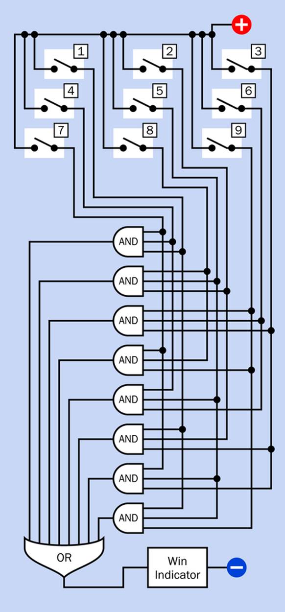
Figure 23-4. A logic diagram for Ovid’s Game showing switches that represent one player’s counters placed on the board.
Notice the eight-input OR gate at the bottom of each diagram. Does such a thing exist? Yes, it does, so this is not a problem. Likewise, three-input AND gates are easy to find. How many will be needed? There are eight different ways to win, so that will mean eight three-input AND gates. There are three of these gates on a 14-pin chip, so three chips will do it.
This will only detect one person’s win-or-lose situation. To detect the other person’s status, another set of switches and another set of logic chips will be needed—but if you want to give yourself less work, you can have a master switch to identify which person is taking a turn, and it will apply power to the same set of chips through one player’s set of switches, or the other.
I’m not sure I like either of these options. So now let me suggest an alternative.
Switching Ovid
Ovid’s Game (or tic-tac-toe) turns out to be ideal to be wired by multipole switches, without using any logic gates at all. By now you should be able to figure out this kind of circuit yourself, but I’m showing you the one that I came up with in Figure 23-5. (Can you derive a simpler version?)
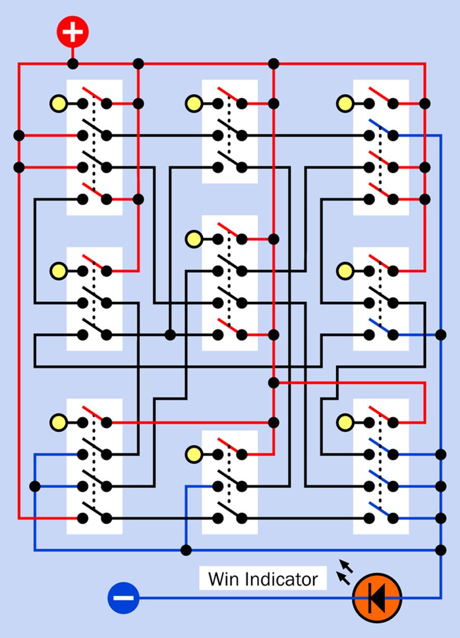
Figure 23-5. Ovid’s Game can be modelled using switches without logic chips.
To see how this works, begin by imagining that one of the switches has been closed, and follow the positive current through other switches to the negative ground wire. It’s really much simpler than it might first appear.
The little yellow circles will be small LEDs that light to confirm that a switch has been pressed. Naturally they will have to be connected with negative ground, but I omitted those connections to keep the schematic simple.
As you see, each switch will require three or four poles. Actually I was able to model the game using two-pole switches, but that required omitting the little LEDs.
You can buy 4PDT latching pushbuttons very cheaply, which will do the job. The big LED at the bottom lights up when the player has pressed three switches in a row.
A separate array of nine switches will be required for each player, making eighteen in all, as suggested in the rendering in Figure 23-2.
Do you like the logic-chip version of the game, or the switched version?
You know—moving counters around a board and using sensors to detect their position is clearly the best way to do it, so I really will come back this later, but in the meantime, I think you’ve had enough practice to build this game yourself. You can use wired switches or logic gates and retrofit it with sensors later.
Making Even More
I mentioned earlier that I don’t know how to build a circuit that’s smart enough to play this game. However, I think I could do it using software. A typical microcontroller has relatively little memory, but Ovid’s Game allows so few possibilities for each move, a program might be able to handle it by using just four rules, in order of precedence. These rules would tell the microcontroller what to do (and you could test them by following them yourself, if you play the game with someone):
§ If you can move a counter to make three in a row, do that. Otherwise—
§ If your opponent can move a counter that will create three in a row, try to block him. Otherwise—
§ If you can move a counter into the center cell, do that. Otherwise—
§ Move a counter at random into an unoccupied square. If this is not possible, the game is a tie.
This program wouldn’t win many games, but it would work. The problem is, it would have to represent the playing board and the counters in computer code, which really requires the use of integer arrays. On an Arduino, in C language, there is no error checking to make sure that you stay within the bounds of an array, and there are some other features that I don’t like too much. Even now, most microcontrollers are less powerful, less user friendly, and less error proof than the old IBM-PCjr on which I used to write games in Microsoft BASIC, back in the 1980s. What a sad state of affairs!
My friend Fredrik Jansson, a physicist from Finland who helped with fact-checking this book, suggested that you could implement Ovid’s Game with a microcontroller if you used a desktop computer to do the initial hard work. Fredrik calculated that there are 1,680 possible positions of three black counters and three white counters on the board. Because a position is logically the same if the black and white counters are swapped, really there are only 840 logically different positions. This number is small enough to allow a computer to play out every possible game and establish the best move in every situation.
If you use the computer to compile a table of all the best moves, you can install that table in the limited memory of a microcontroller. Fredrik figured that you only need four bits for each recommended move: two bits to select a counter, and two bits to instruct it to move up, down, left, or right. Therefore, the instructions for playing 840 logical positions could fit into 420 bytes. You’d still need some extra instructions for initial placement of the first three markers of each color, but still, this scheme looks doable. Each time a human opponent made a move, the microcontroller would just look up the best response that was previously determined by its more powerful cousin, the desktop computer.
If you decide to try this programming strategy, or any other, please be sure to let me know how it works out.
Answer to the Puzzle
The answer to Dudeney’s puzzle about the window is shown in Figure 23-6. The window measures two feet on each side, and each triangular pane measures one foot on each side. Therefore, the layout satisfies the requirements of the problem. Wait—you didn’t assume that the window had to be square and each pane had to have four sides, did you?
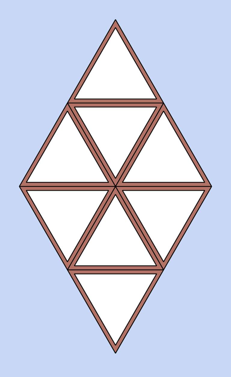
Figure 23-6. The solution to the “window puzzle” posed at the beginning of this section.
If you like this kind of puzzle, either to amuse yourself or confound your friends, there are two compilations of Dudeney’s life work: The Canterbury Puzzles and Puzzles and Curious Problems. Because they were published so long ago, they are now out of copyright and you can read them freely (and legally) online through The Gutenberg Project.
You can also get Ovid’s Game as an Android app, if you want to practice against a computer-opponent. But I think building something of your own is more interesting.
All materials on the site are licensed Creative Commons Attribution-Sharealike 3.0 Unported CC BY-SA 3.0 & GNU Free Documentation License (GFDL)
If you are the copyright holder of any material contained on our site and intend to remove it, please contact our site administrator for approval.
© 2016-2026 All site design rights belong to S.Y.A.