Practical Electronics: Components and Techniques (2015)
Chapter 10. Relays
Relays may be an old technology, but they are still essential in electronics. A relay is basically just an electrically operated switch. Some are tiny and handle only small amounts of current at low voltages, whereas other types, called contactors, are huge (the size of a small refrigerator) and can safely deal with hundreds of amperes and thousands of volts. But regardless of size and power capacity, all relays and their close cousins the contactors use the same basic principle of operation.
This chapter describes various types ranging from low-current TTL-compatible reed relays to high-power types used to control AC. Techniques for controlling a relay from a low-voltage circuit are also covered, as well as some examples of how relays can be used in control and logic circuits.
Relay Background
Relays have been around since about 1830. In fact, they are probably one of the oldest types of electrical components (other than perhaps switches). Relay-based switching systems replaced human telephone switchboard operators in mid–20th century, and some early computers were built using relays, such as the Zuse Z3 (1941), the Atanasoff-Berry Computer (1942), and the IBM ASCC/Harvard Mark I (1944). Although they haven’t changed much in terms of operation, they have evolved into a myriad of types over the past 180 years.
Regardless of the actual internal physical arrangement, all electromechanical relays operate on the principle of electromagnetism as the force driving a mechanism of some sort. The mechanism might be an armature, metal reeds, or a contactor bus bar type of arrangement.
Armature Relays
An armature relay has an internal mechanism that transfers the motion induced by a solenoid coil (an electromagnet) into physical motion, usually by means of some sort of lever action. The motion of the armature can be used to control multiple sets of contacts, and in some designs, a small pushbutton is brought out through the shell of the relay to allow manual operation. Figure 10-1 is a simplified illustration of a basic SPST type of relay.
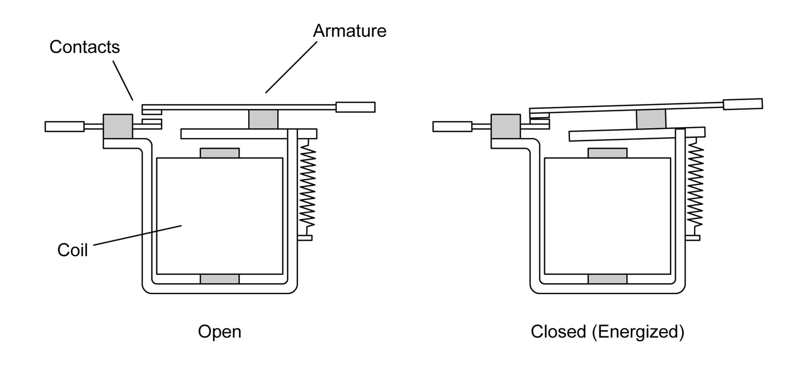
Figure 10-1. A basic electromagnetic relay
Armature type relays can have one or more sets of contacts (SPST, SPDT, DPST, DPDT, 3PDT, and so on), with the multiple contacts all mechanically connected to the same armature lever. Since they are basically electromechanical switches, the same general contact descriptions apply. But relays have the advantage of an electromagnet, which can exert considerable force. Relays with 10 or even 20 sets of contacts are sometimes found in applications such as elevator controls and old-style telephone switching systems. If you look ahead to Figure 10-8, you can see three sets of SPDT contacts through the clear plastic shell of the relay.
Reed Relays
Some types of relays use a set of thin metal strips called reeds for the contacts. These are sealed into a small glass tube, and a coil wound around the tube provides the electromagnetic force that causes the reeds to bend and make contact. Figure 10-2 shows how this type of device works.
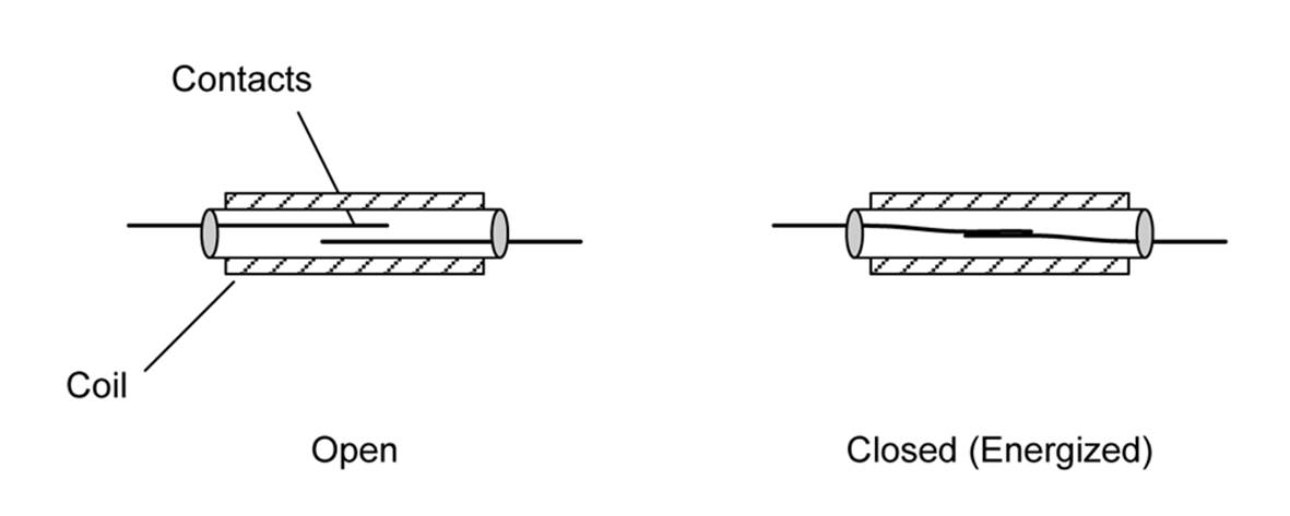
Figure 10-2. Reed relay operation
Any suitable magnetic field will cause the reeds to flex and make contact. In fact, the sensors used in security systems to detect an open door or window are often nothing more than the reed in its glass tube without a coil. A permanent magnet in the window or door frame closes the contacts when it’s close to the sensor. Figure 10-3 shows a bare reed sensor module suitable for use with something like an Arduino or BeagleBone single-board computer.
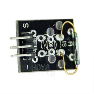
Figure 10-3. Reed contacts without a coil
Contactor
In a high-current, high-voltage type of relay known as a contactor, a solenoid coil is used to pull in a bar or frame that holds the contacts, as shown in Figure 10-4. The result is rather like a piston, with the bus bar making a shorting connection between the input and output terminals of the device.
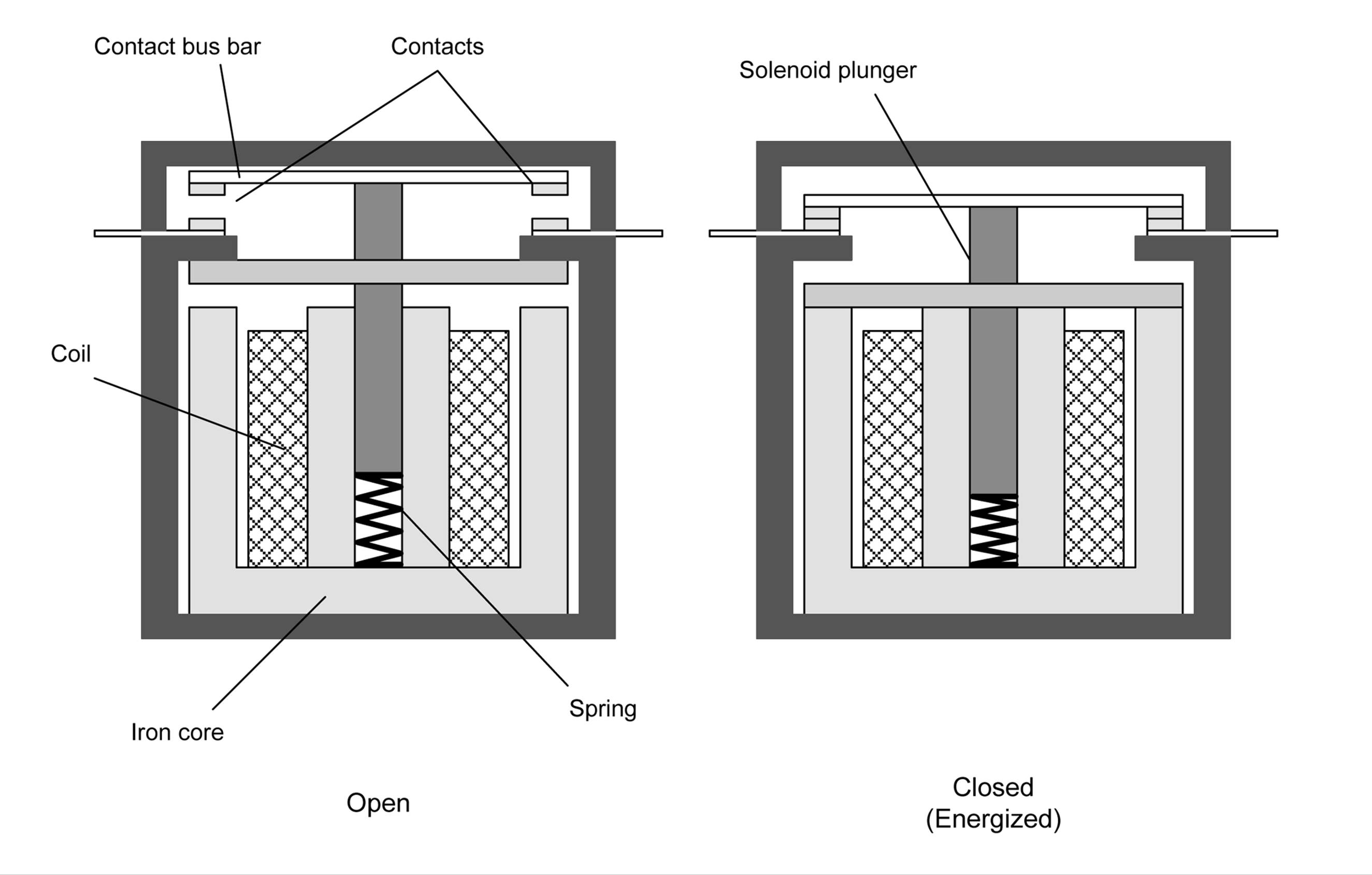
Figure 10-4. Operation of a heavy-duty contactor
Large contactors can be startling when they are energized, producing a loud bang as the bus bar is pulled in by the solenoid.
Relay Packages
Some relays are minuscule, while others are huge. Relays come in printed circuit board form factors with both through-hole and surface-mount packages. They can be found in packages that use a socket, making them easily replaceable. Other types have lug terminals for use in industrial and automotive applications, and still others have large bus-bar connections for applications such as high-power motor controllers. It all depends on how much current they are designed to handle at a given voltage and how much voltage and current is necessary to drive the relay mechanism.
PCB Relays
Small relays for PCB applications are available in types that range from reed relays to compact armature devices that are capable of handling up to 120 VAC at 10A or so. The previous section showed what a reed relay looks like (in Figure 10-3). Figure 10-5 shows a compact relay designed to be mounted to a PCB.
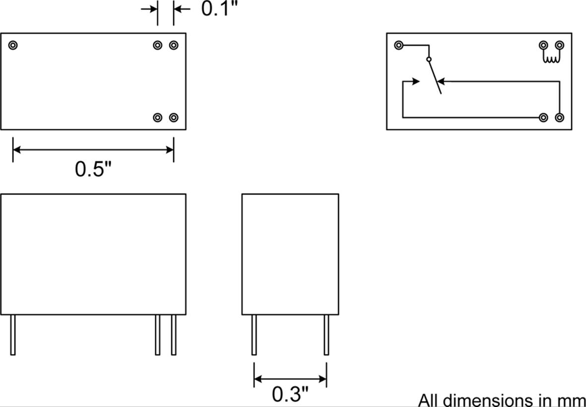
Figure 10-5. A PCB-mounted low-voltage relay
The contact ratings for a relay of this type can be substantial, even through the relay coil itself requires only 70–85 mA at 5V DC to operate. The actual coil current depends on the resistance of the coil, and this can vary between models and manufacturers. Note, however, that even 70 mA is way beyond the output capability of most ICs, so some type of relay driver IC or a transistor is needed to operate the relay, as described in “Controlling Relays with Low-Voltage Logic”. You can find relays of this type controlling things like lighting, heater elements, small electric motors, and as drivers for larger heavy-duty relays and contactors.
Reed relays are also available in packages that look like a typical 14-pin IC, as well as packages that have bare wire leads for the contacts and the coil. A reed relay might have a coil with a high enough resistance to allow it to be driven directly from a microcontroller or logic IC, but a reed relay usually won’t carry as much current through its contacts (the reeds) as an armature type of relay.
Both miniature armature and reed relays are available in through-hole and surface-mount packages. The surface-mount relay shown in Figure 10-6 is an example (all dimensions are in millimeters).
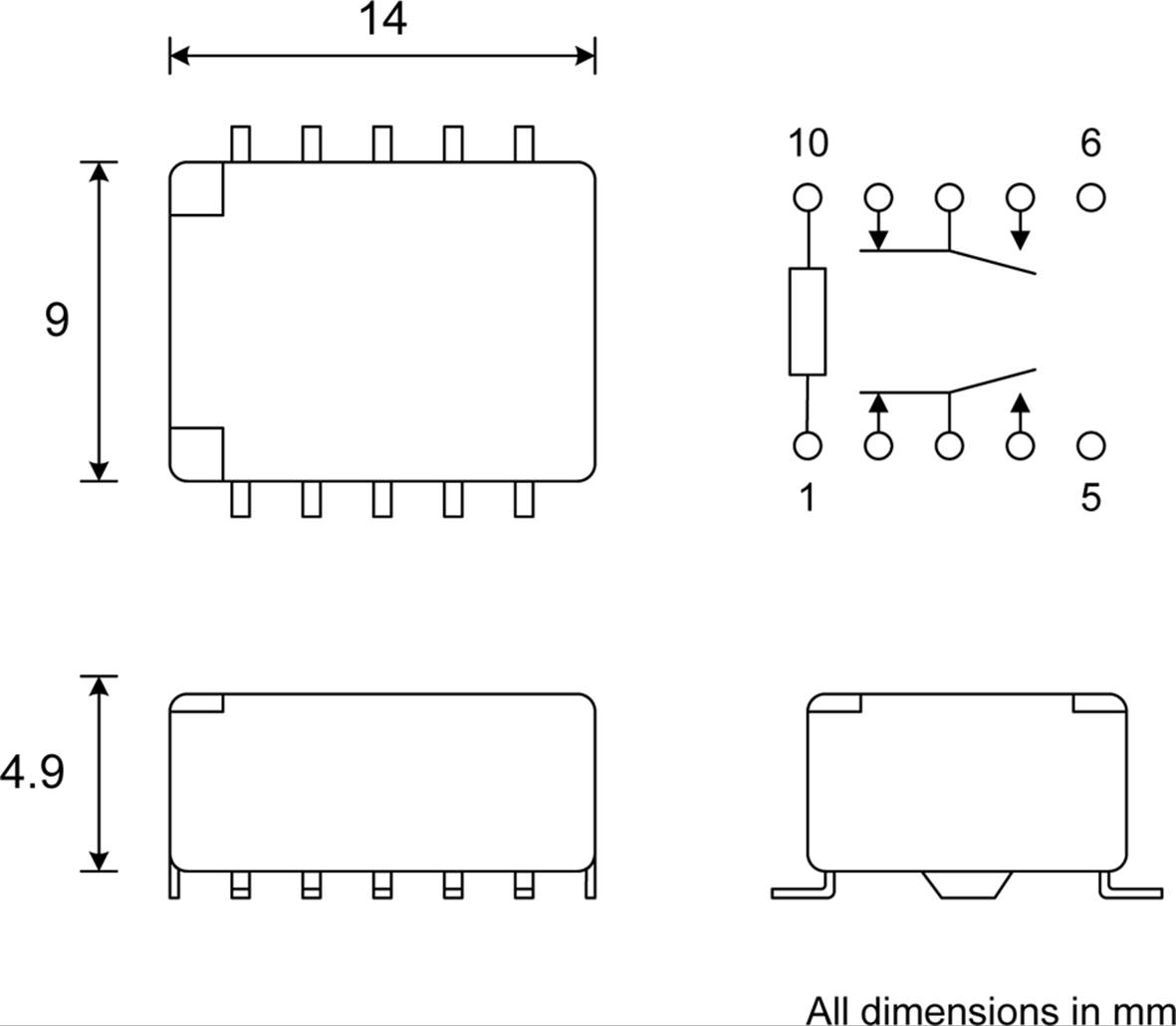
Figure 10-6. Surface-mount, low-voltage relay
This happens to be the package drawing for a Panasonic TQ series relay, but similar parts are available from Omron, NEC, and other manufacturers. The TQ2SA-5V has a 5V DC coil at 178 ohms with a nominal power consumption of 140 mW, and nominal contact ratings of 0.5 A at 125V AC.
Lug-Terminal Relays
Relays with terminals specifically designed to accept lug connectors, such as those used in automotive and industrial applications, are available in both vertical and horizontal mounting styles. Coil voltage ratings are available in both DC and AC values covering the range from 5V DC to 110V AC, or more. Figure 10-7 shows an example of an automotive lug-terminal relay with right-angle mounting brackets. The coil operates at 12V DC, and the SPDT contacts are rated for 12V DC at 40 A.
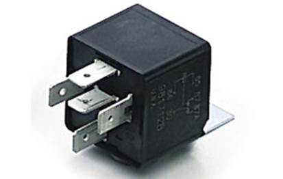
Figure 10-7. Right-angle-mounted lug-terminal armature relay
This type of relay uses the crimped lug connectors discussed in Chapter 7 and the crimping tool shown in Chapter 3. Although it is possible to solder to the terminals, this is generally not a good idea. Long ago, when the base of the relay assembly was made of Bakelite, it wasn’t as big of a problem, because Bakelite can tolerate the heat of soldering. Modern relays are made using plastics with much lower melting temperatures, and it is possible to deform the base and cause the terminal to shift during soldering.
Socketed Relays
Many early relays used solder terminals for connections, so replacing one was an exercise in desoldering and resoldering the wiring. As this was a tedious and error-prone process, clever engineers devised a means of using sockets for relays, along the same lines as the sockets used for vacuum tubes. Some socketed relays use round sockets with eight contact positions, like the one shown in Figure 10-8, while others use a rectangular socket with the holes arranged in a grid pattern. Both types typically bring out the relay connections to screw terminals, and either spade or ring lugs are used to connect the wiring.

Figure 10-8. A typical octal (eight-pin) relay socket with screw terminals
These types of relays are mostly used in industrial applications that involve switching high voltages and large amounts of current. They are also available in an 11-pin form.
Although octal sockets might seem like a throwback to the days of vacuum tubes, they are still quite common and readily available. It is also possible to purchase just the octal plug and put your own electronics into it. This is useful for applications where you might want a sealed module (like, say, a sensor data collector for a remote environmental monitor) that can quickly and easily be replaced if necessary.
Selecting a Relay
Relays have two sets of primary specifications: coil and contacts. The coil will have a nominal operating voltage and resistance, although sometimes the manufacturer will give a power value instead of a resistance. If the current isn’t specified, a quick application of Ohm’s law will tell us how much current we can expect the relay coil to draw, and we can use the power specification to figure out the coil resistance (see Chapter 1).
The contacts should be rated to handle the load they will be controlling and then some. To be safe, it’s a good idea to derate the contacts by 50%, meaning that if you want to control a 240V, 40 A contactor with a 24V AC coil that draws 36 mA with a driver relay, the smaller relay will need to have contacts that can handle 72 mA at 48V AC (twice the current and voltage actually required). A smaller relay is used in this case because the contactor uses AC for its coil, not DC. This makes it more challenging to control with just a solid-state driver circuit, although it is possible (and not uncommon). Using a small intermedite relay to handle the AC for the contactor’s coil keeps things simple.
A small relay rated for 100 mA contact current should do fine for this application. It also implies that, for a situation like this, you could use a miniature PCB-mount relay, like the units shown in Figure 10-9 (this is a bank of four, with built-in drivers).
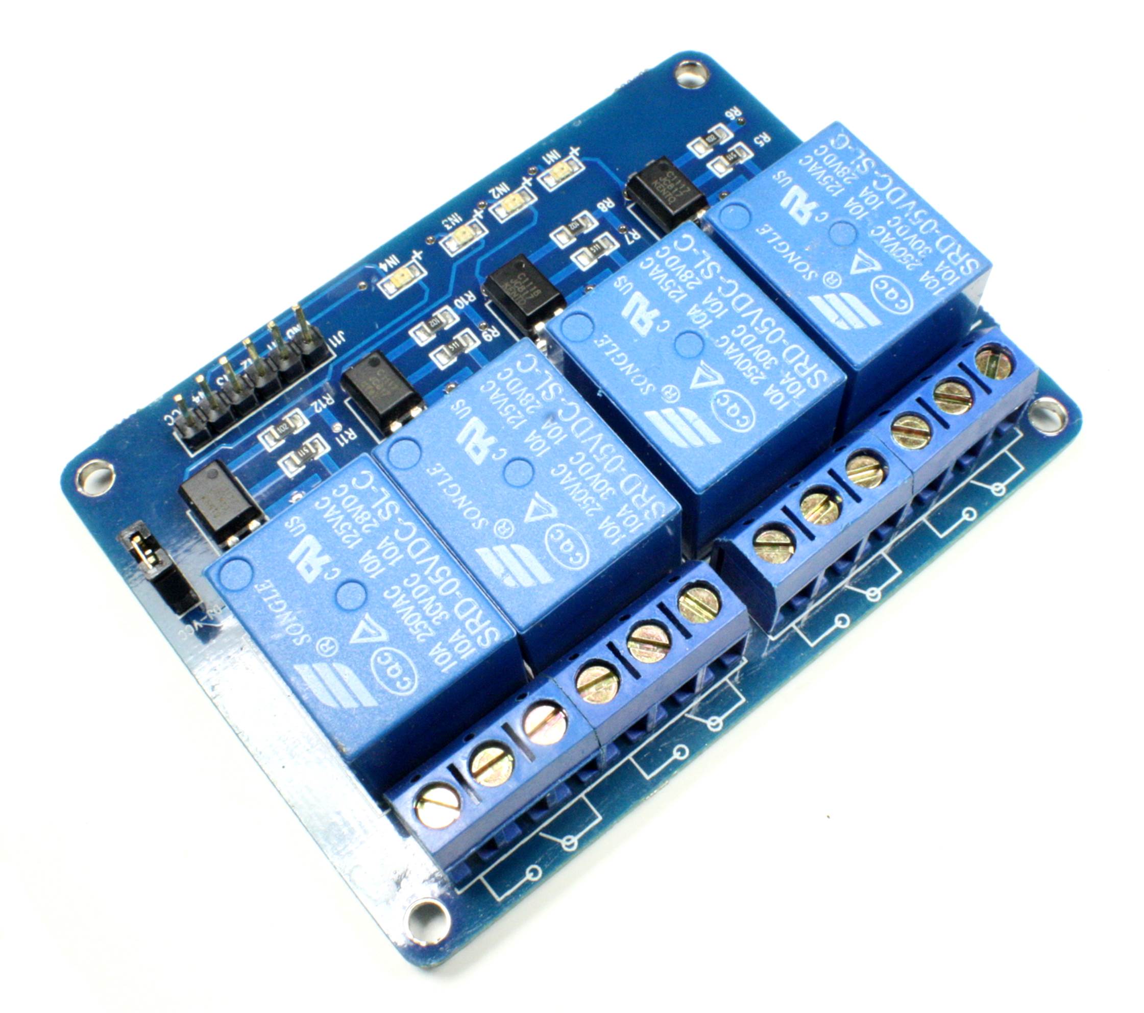
Figure 10-9. Relay module for use with a microcontroller
However, a small relay might require anywhere from 20 to 50 mA for its coil, which means it can’t be controlled directly from a standard logic IC or microcontroller. In this case, either a driver IC or a transistor driver (as described in “Controlling Relays with Low-Voltage Logic”) will be needed. The board shown in Figure 10-9 doesn’t have this problem, because the drivers are already on the PCB.
A cascade of relays is not an uncommon situation. Figure 10-10 shows how a sequence of relay driver, small relay, and contactor can be connected to control a high-current, high-power system. Conceptually, this can be extended as far as necessary, so that, in theory, a 5V logic signal could control hundreds of amperes of current.
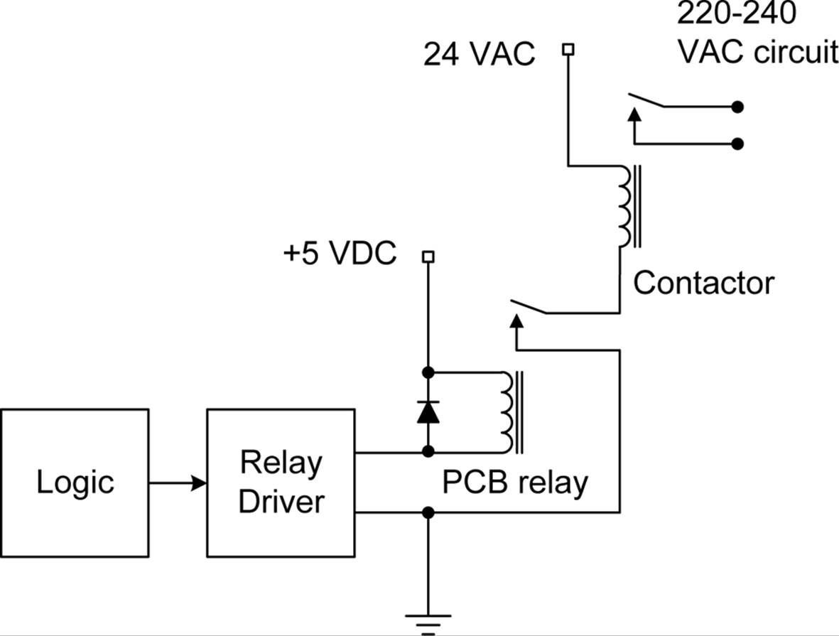
Figure 10-10. Using a small relay to control a larger relay
Relay Reliability Issues
Modern relays are fairly reliable, with claims for some small low-current types of over 10,000,000 mechanical cycles with no load. But relays are mechanical devices, and that implies wear and tear on the operating parts.
In a relay, a failure occurs when either the contacts can no longer pass current effectively or the relay’s coil will no longer operate the contact mechanism. Two major sources of relay failure are contact arcing and coil overheating.
Contact Arcing
Of course, the more load (power) a relay carries, the more the contacts will wear due to arcing. At some point, a loaded relay might actually burn the contacts to the point where they no longer make good contact. In other words, the contacts start to become resistors, or even open circuits. This can be a major problem when a relay is controlling an inductive load, such as a motor or another relay.
You can reduce arcing using a resistor-capacitor (RC) snubbing circuit to help damp out the arc at the contacts. Figure 10-11 shows one way to do this. This technique works for both DC and AC circuits, and it can help extend the life of a relay’s contacts considerably.
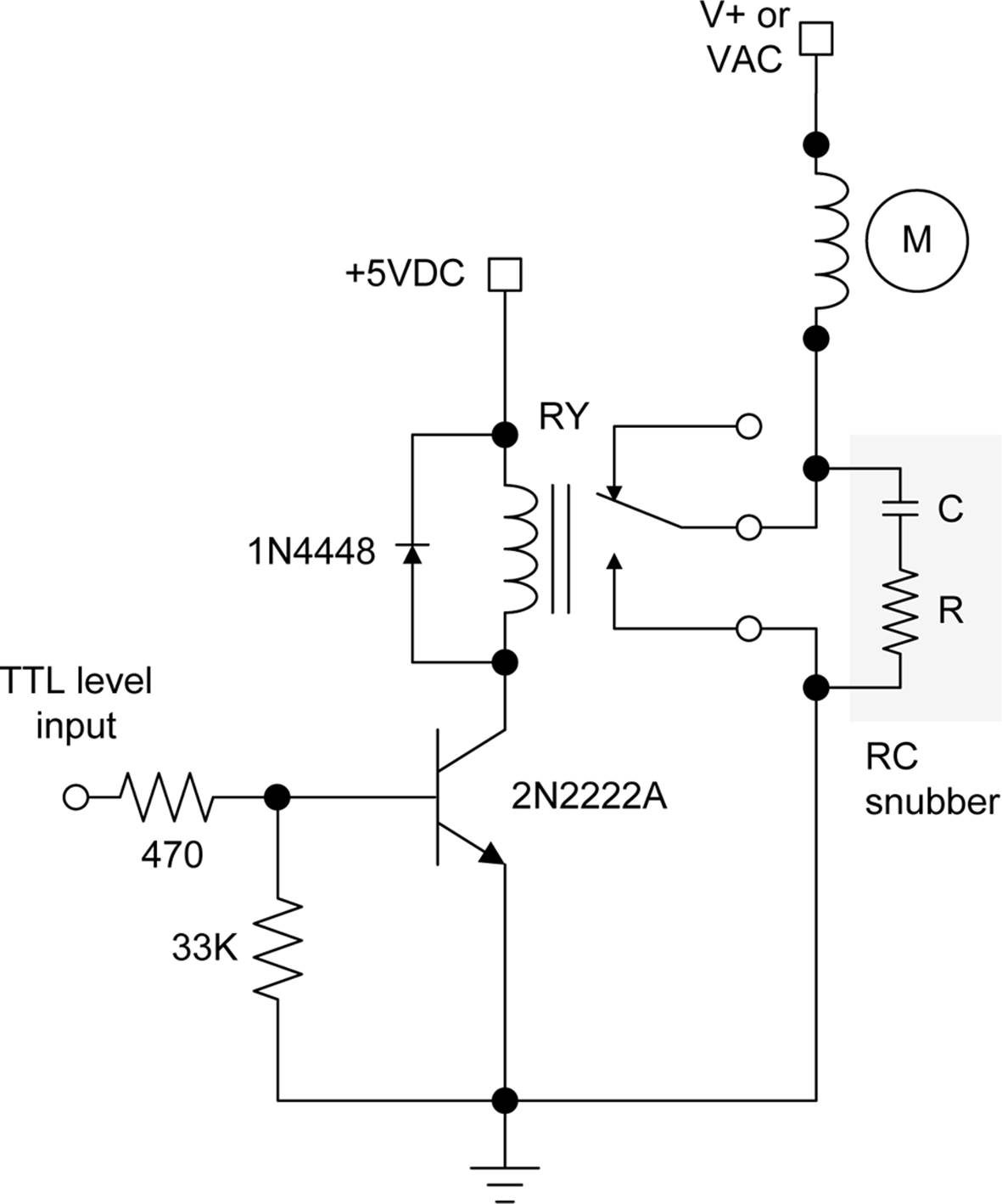
Figure 10-11. Relay contact snubber
Remember, if you need some assistance with the schematic symbols or electrical concepts presented in this section, refer to Appendix A or Appendix B.
The idea behind a snubber is that the combination of R and C will reduce the effect of spikes experienced by the relay contacts when power is removed from an inductive load, in this case a motor (M). When current flow through an inductive load stops, the magnetic field around the windings in the load will collapse, generating a large voltage spike. The RC circuit acts to stretch the spike so that by the time it reaches its maximum voltage, the relay contacts are far enough apart that an arc can’t form between them. Appendix A includes the equations for calculating values for an RC circuit.
In some high-power contactors, the contacts are made from a silver alloy. Since there will always be some arcing in high-current/high-voltage applications, the contacts will start to oxidize. But with silver contacts, the result is silver oxide, which is itself a decent conductor.
Coil Overheating
Coil overheating will cause the coil to deteriorate as the insulation becomes brittle and breaks down. This will eventually result in shorts in the windings, which will cause it to draw more current and get even hotter. It is not unheard of for a relay to burst into flames when the coil severely overheats, due to progressive shorts in the windings. The easiest way to avoid this situation is to ensure that the relay isn’t being driven with more than its rated voltage. If possible, the circuit should be designed so that the default state of the relay is off, not on. Putting a fuse in series with the coil of a relay is another way to help prevent a catastrophic failure.
Relay Bounce
Just like a mechanical switch, the contacts of a relay have a tendency to bounce when the relay closes. The resulting output from the relay looks something like Figure 10-12.
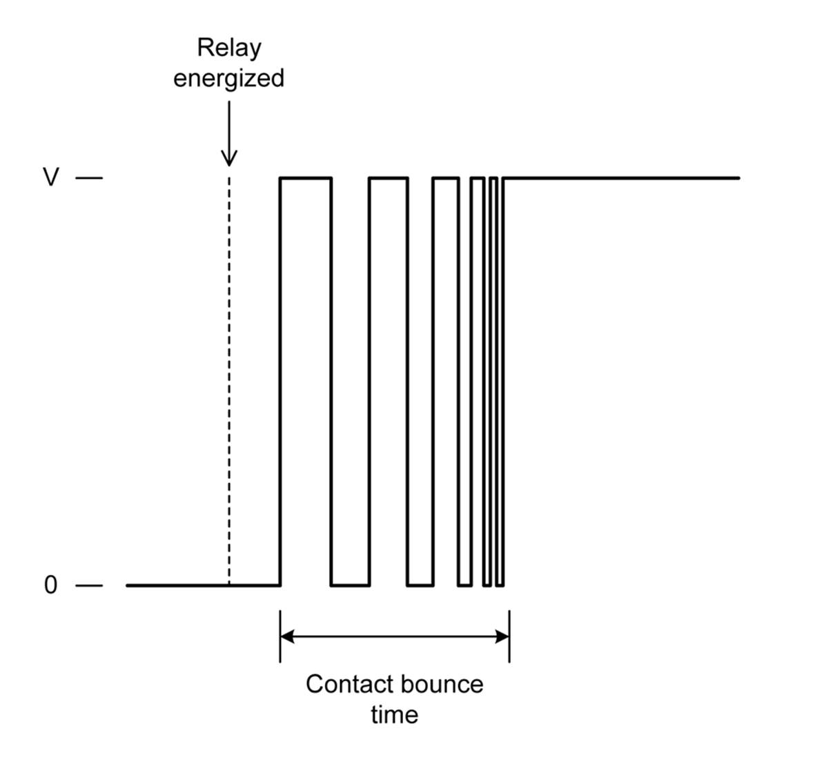
Figure 10-12. Relay contact bounce
If a relay is connected to another relay, or to something like a lamp, LED, or a motor, the contact bounce isn’t a real big issue, except that it does prolong contact arcing and subsequent wear (each bounce is an arc, even if tiny). The arc suppression techniques mentioned earlier can help reduce the effects of contact bounce on the relay contacts.
If a relay is connected to a digital circuit of some type (as an input, for example), bounce can be a big problem. In a situation like this, the input will need to be debounced, either by logic hardware or by software. Relay bounce can also sometimes be heard if a relay is switching an audio signal. It’s the “crunchy” blip or pop that occurs when the audio input is switched from one source to another using a set of relays.
Relay Applications
Relays are useful for routing signals, switching current, or as a form of logic for some applications. While is it possible to use a solid-state component to do switching and routing chores, the relay offers the advantage of low closed-circuit resistance, immunity to reverse current flow from inductive loads, and the ability to act as an isolated control transition between low- and high-voltage circuits.
Controlling Relays with Low-Voltage Logic
A relay uses a coil to move the contacts, so it’s an inductive load to whatever is driving that coil. An inductor will produce a current in the reverse direction when the energizing current ceases to flow and the magnetic field collapses, and the resulting voltage spike can be quite large. A relay coil can also draw a considerable amount of current, much more than most ICs can safely handle.
Some relays are made specifically for use with logic circuits, which means they will have a low coil-current (high resistance) and a built-in protection diode. However, the coil-current general-purpose relays with 5V DC coils can range anywhere from 20 to 80 mA, so this type of device should not be connected directly to something like a TTL logic chip or a microcontroller without some kind of interface circuit. The current through the coil will overwhelm the IC and probably damage it. Figure 10-13 shows one way to deal with this situation with an NPN transistor (a 2N2222A), a couple of resistors, and a diode.
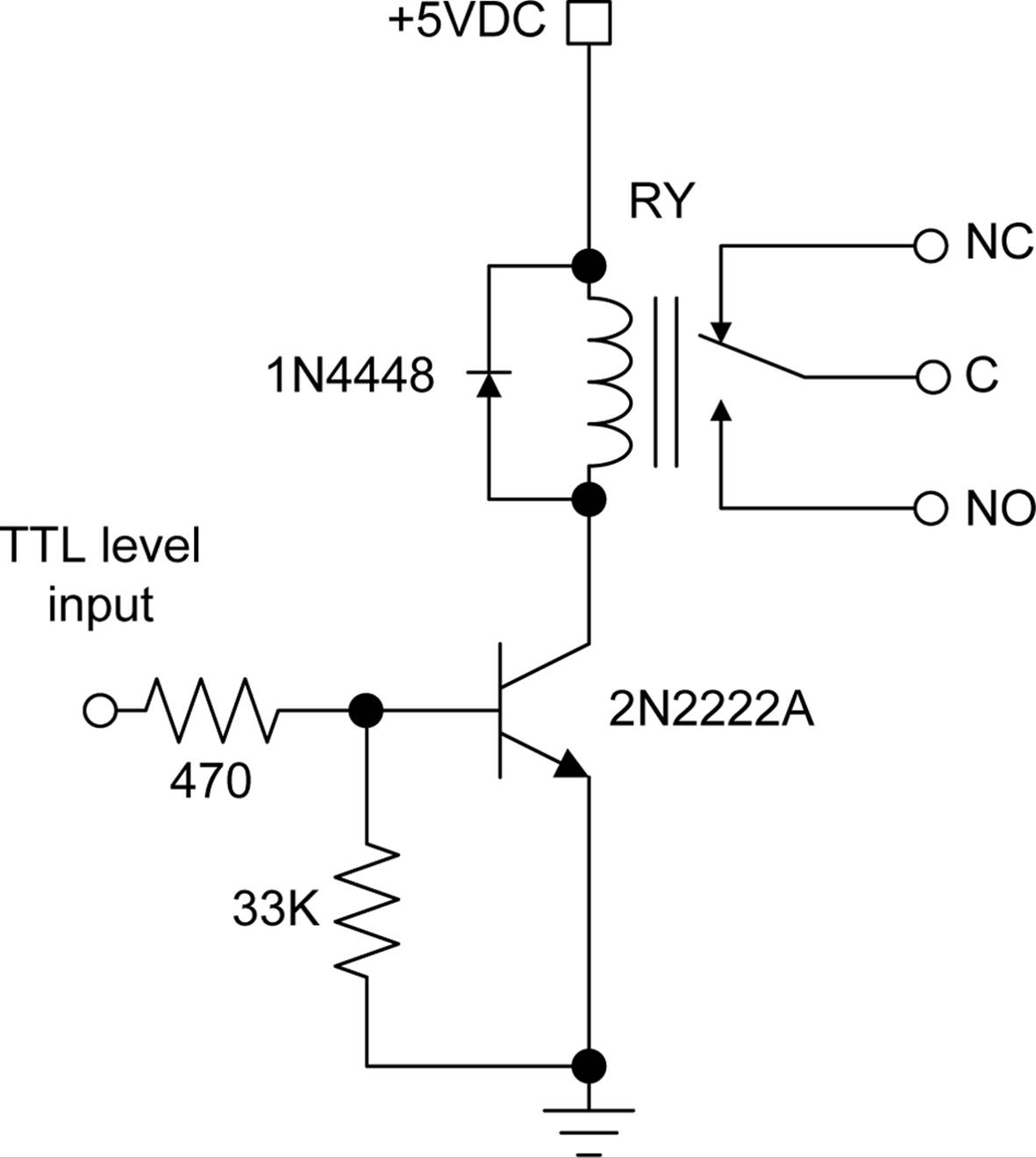
Figure 10-13. Simple one-transistor relay driver
This circuit is simple and effective, but relay driver ICs are also available that package from one to eight relay driver circuits into a single chip. The single-channel devices might be an option if you need to drive only one relay. Table 10-1 lists some of the available relay driver ICs.
|
Part number |
Manufacturer |
Internal logic |
Drive current |
|
CS1107 |
On Semiconductor |
Single driver |
350 mA |
|
MAX4896 |
Maxim |
8-channel driver |
410 mA single, 200 mA all |
|
SN75451B |
Texas Instruments |
Dual AND driver |
300 mA |
|
SN75452B |
Texas Instruments |
Dual NAND driver |
300 mA |
|
SN75453B |
Texas Instruments |
Dual OR driver |
300 mA |
|
SN75454B |
Texas Instruments |
Dual NOR driver |
300 mA |
|
TDE1747 |
STMicroelectronics |
Single driver |
1A |
|
UDN2981A |
Allegro |
8-channel driver |
500 mA max, 120 mA/channel |
|
Table 10-1. Relay driver ICs |
|||
Note that the parts in Table 10-1 can be used to drive things other than a relay, such as lamps, valves, actuator solenoids, high-current LED displays, and so on. Also, many of the parts listed here will work with CMOS as well as TTL logic levels. Check the datasheets from the manufacturers for details.
Signal Switching
Figure 10-14 shows a device (an HP 3488A switch/controller) that is typically used to route signals between different types of measurement equipment and devices or circuits under test. The switching is done by banks of relays mounted on PCBs that plug into the rear of the unit. The 3488A can be programmed to perform switching actions at specific times, but it can also be controlled using a GPIB/IEEE-488 control interface to a PC or other control device providing the commands to route signals through the relay banks.
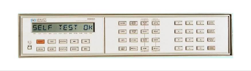
Figure 10-14. The HP 3488A switch/controller unit
Small relays can be used to switch standard video signals or select inputs for a measurement device. They were commonly used in the past to route telephone circuits, although that function has been largely replaced by solid-state components. For signal switching, reed relays are often used.
Power Switching
An example of using relays for power switching might be a situation where there is a need to control things like pumps, valves, and heaters for a marine specimen holding tank. Relays are a good choice for this, because a relay can operate a 120V AC pump as easily as a 12V DC pump. The main consideration would be the voltage and current ratings for the contacts.
Air conditioning units employ heavy-duty contactors to control various fans and compressors. The input to the contactors is often a low voltage like 24 VAC that is controlled by a thermostat. A conventional mechanical thermostat can be replaced with a microcontroller and a relay to create a custom programmable controller without the need to worry about creating a suitable circuit to interface directly with the existing A/C control voltage.
Relay Logic
As mentioned earlier, some of the first computer-like systems were based on relays. It was a natural choice, given that the telephone switching networks were starting to use relays for dynamic circuit routing. The rotary dial on old-style telephones wasn’t an aesthetic design decision; it was like that because each pulse produced by the dial as it spun back to the start position drove a rotary relay at a switching office somewhere. The caller effectively modified the network wiring between her phone and whomever she was calling every time she dialed a number. Multiple banks of rotary relays allowed simultaneous calls to go through the system, and huge windowless buildings once held thousands or even tens of thousands of relays, all chattering away at the same time.
Creating a latching circuit is straightforward, as shown in Figure 10-15. In the simple design shown in circuit A, the relay is held closed by a second set of contacts. Once the relay is energized, the current flow through the contacts will keep it energized until the connection to ground is opened by the normally closed switch. Note that this circuit will work for both AC and DC, up to the maximum voltage that the switches and relay contacts can tolerate.
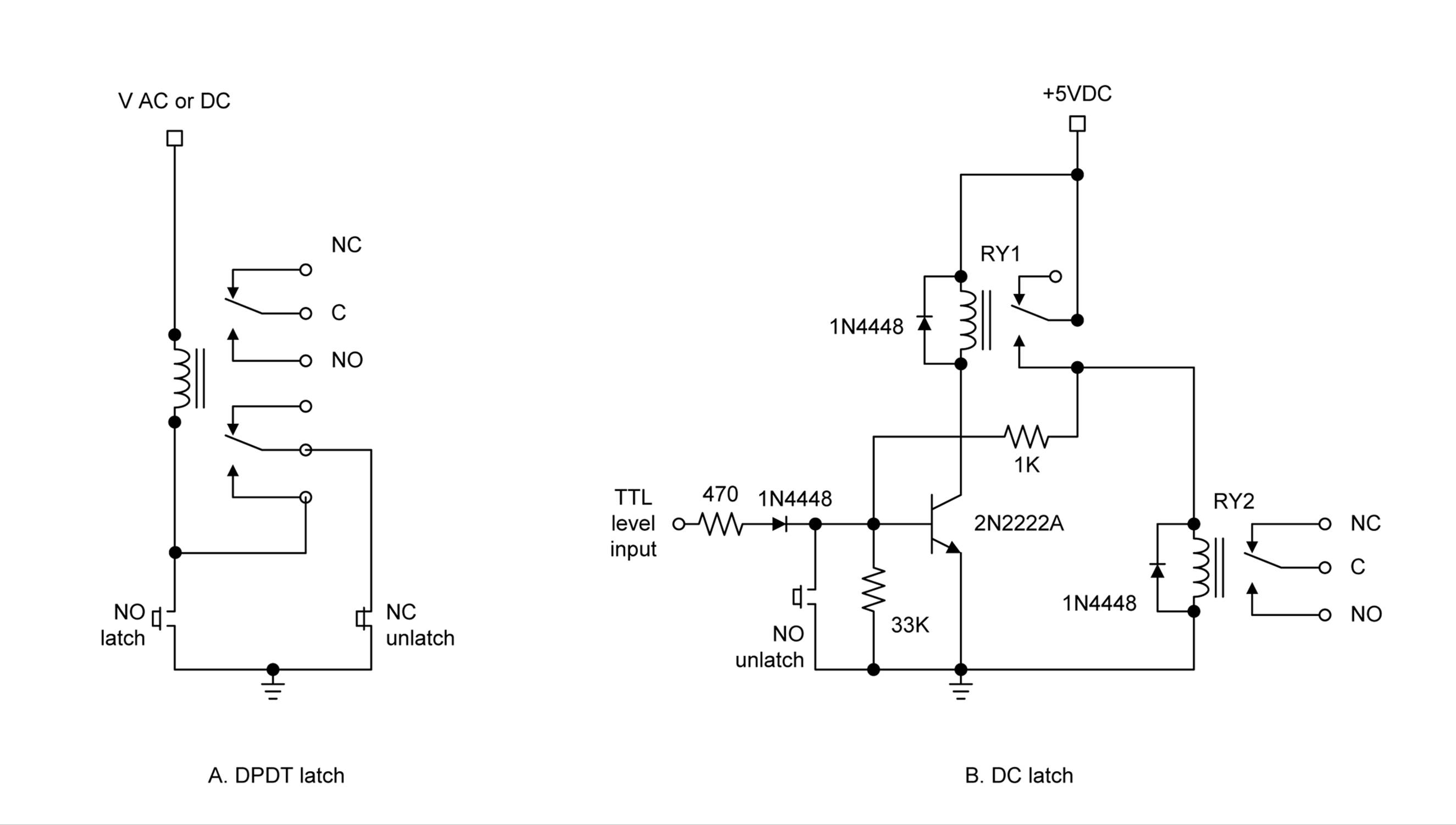
Figure 10-15. Latching relay circuits with manual reset
The circuit in part B of Figure 10-15 is intended for use with 5VDC only, and it’s basically just a variation on the driver circuit shown in Figure 10-13. The main difference is that, when RY1 is energized, it will supply 5V back into the transistor via the 1,000 (1k) ohm resistor, thus keeping it in an on state. When the pushbutton switch is pressed, the base of the transistor will be grounded, current flow through RY1 will stop, and the relay will open, thus breaking the lock.
It’s easy to construct OR and AND logic using relays (see Chapter 11 for more about logic devices), as shown in Figure 10-16. There are other ways to get the same results, using relays, but the idea here is to show how the standard truth tables for OR and AND can be satisfied with just a couple of SPDT relays. You can construct logic circuits for NOR, NAND, and XOR functions as well.
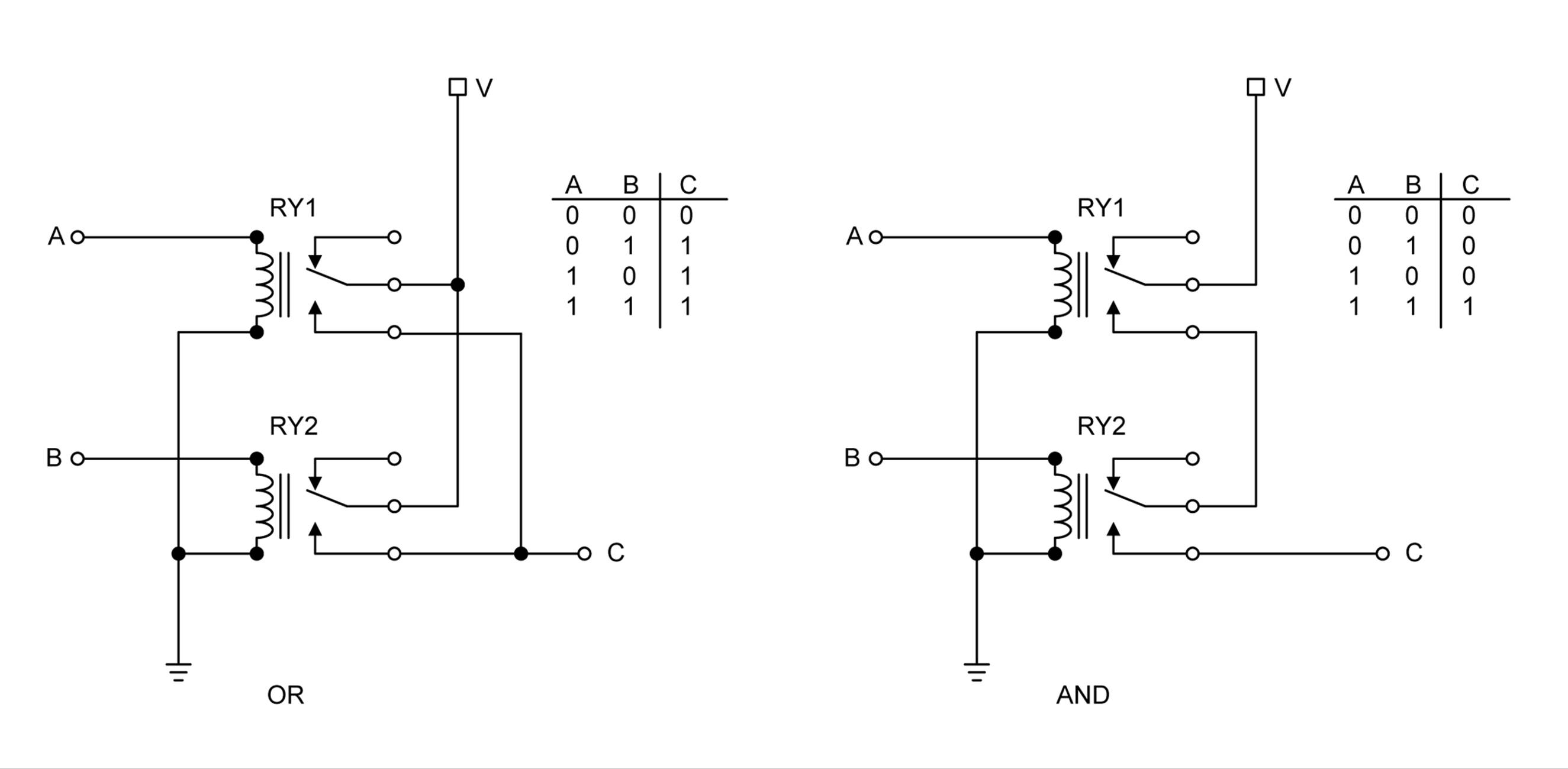
Figure 10-16. Simple OR and AND relay logic circuits
This isn’t as esoteric as you might think, and relay logic appears in various guises in circuits found in industrial controls, home appliances, automobiles, and even in some avionics. Eventually, however, even these applications will become the domain of solid-state controls and switches. But for now, relays are still very much alive and well, and when you’re dealing with the interfaces between systems operating at vastly different voltage and current levels, a relay may be the easiest and cheapest way to get the job done.
Summary
This chapter identified the three major types of relay mechanisms: armature, reed, and contactor solenoid. It also covered some of the available package types, including PCB, lug terminals, and sockets.
We also briefly examined some of the ways that relays can fail, and some of the techniques available to reduce the likelihood of failure. Lastly, we wrapped up with a look a relay latching and relay logic.
You should come away from this chapter with a sense of what types of relays are available and some of the ways they can be used. While it is beyond the scope of this book to delve into the theory behind things like one-shot debounce timers and complex relay logic, Appendix C lists some excellent references if you want to explore the topic further.
All materials on the site are licensed Creative Commons Attribution-Sharealike 3.0 Unported CC BY-SA 3.0 & GNU Free Documentation License (GFDL)
If you are the copyright holder of any material contained on our site and intend to remove it, please contact our site administrator for approval.
© 2016-2026 All site design rights belong to S.Y.A.