Practical Electronics: Components and Techniques (2015)
Chapter 7. Connectors and Wiring
Wires and connectors are the glue that binds electronic components, assemblies, and devices into cohesive systems. Wires can be the copper traces on a PCB or actual insulated wires from one point to another inside the chassis of a device. The concept of a wire extends to include things like USB cables, power supply wiring, Ethernet cables, and shielded cables carrying audio, video, or RF (radio frequency) signals.
This chapter covers the basics of wire sizes, stranded versus solid wires, and multi-conductor cables. It also looks at shielding and how it is employed to reduce interference from external noise sources, as well as how twisted-pair wires work.
Connectors provide convenient end points for wires and allow the parts of a device or system to be modularized. This makes for easier testing, assembly, and maintenance. Without connectors, we would have to resort to soldering the wires that connect various parts of a device, or removing wires from a circuit if part of it needed to be replaced. At one time, this was indeed the case. If you ever get the opportunity to disassemble an old television set from the 1960s, you should. It is an eye-opening example of how to do things the hard way (but, in all fairness, there weren’t a whole lot of affordable options back then).
Nowadays, connectors are ubiquitous. This chapter presents descriptions of some of the more common of the various types of connectors available and describes where they are typically used. It also covers the techniques used to assemble some of the more common types, such as DB-9, DB-25, high-density terminal blocks, and the 0.1-inch grid spacing pin connectors found on things like the Arduino, Raspberry Pi, and BeagleBone boards. Along the way, it also touches on topics such as soldering, crimping, and insulation displacement connector (IDC) techniques for connector assembly.
This chapter specifically focuses on those types of connectors that a typical human being can easily handle or assemble without resorting to a microscope and tweezers. It doesn’t cover USB connectors, which are not something you would want to assemble by hand if you can avoid it. Nor does it delve into the world of high-reliability connectors used by aerospace and the military, or miniaturized connectors such as the types found in consumer electronic devices, as these typically require special crimping and assembly tools that cost many hundreds of dollars.
Wire and Cable
The terms wire and cable are sometimes used as synonyms, but in general you can think of a wire as a single conductor of some sort and a cable as a collection or bundle of two or more individual wires. For example, the shielded and insulated bundle of wires between a microphone and an amplifier is referred to as a microphone cable, never as a microphone wire. This isn’t a hard-and-fast rule, however, and confusion sometimes arises when size is involved. Large wires, like those used to carry electricity between poles along the side of the road, are sometimes referred to as cables.
Wires come in specific sizes, with different types of insulation, or even no insulation at all. Wire is available as a single solid conductor or as a set of smaller wires in a bundle, called stranded wire. Figure 7-1 shows how smaller wires are twisted into a bundle to create stranded wire, whereas the solid wire is just a single conductor. Figure 7-2 shows cross-section views of both a solid and a stranded wire.
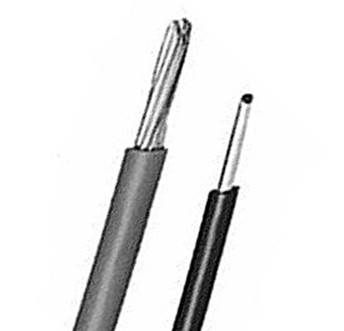
Figure 7-1. Stranded and solid wire
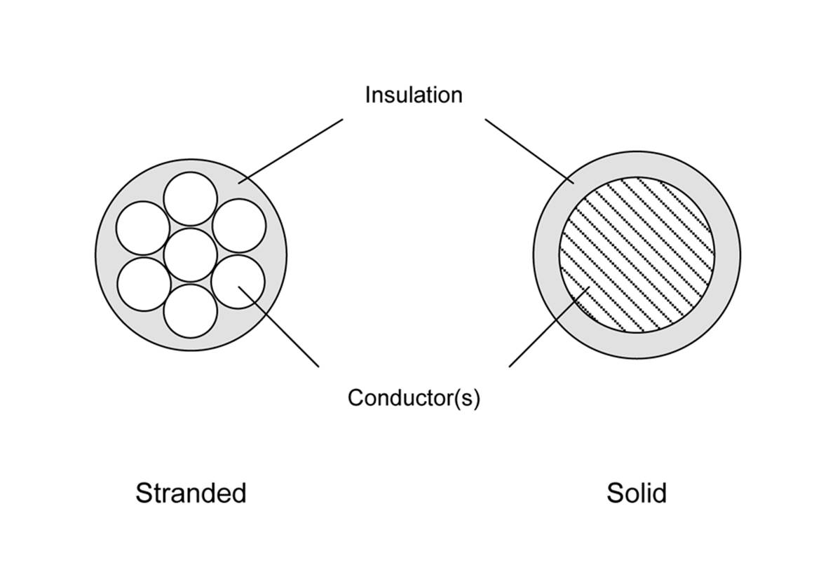
Figure 7-2. Cross-section views of stranded and solid wire
Stranded wire is generally preferable to solid wire because it is more flexible and less prone to breaking, but solid wire still has a role in some applications. Telephone patch bays, for example, contain what are called punch-down blocks and use solid wire. The punch-down blocks work by pushing a solid copper wire between metal blades. These slice through the insulation and make contact with the wire. Of course, there is a special tool for this, but unless you plan to do a lot of telephone-type wiring, it’s not worth buying one.
Solid wire might be a valid option in applications where the wire will not experience any significant flexing and cost is a consideration (solid wire is typically less expensive than stranded wire). For small wire gauges, it is more common to find solid wire, and for applications such as wire-wrap circuit construction, solid wire is the only appropriate choice.
Figure 7-3 shows a selection of insulated wire on small spools, often referred to as hook-up wire. Kits like this can be purchased from electronics distributors and other online sources in a variety of gauges and insulation types.
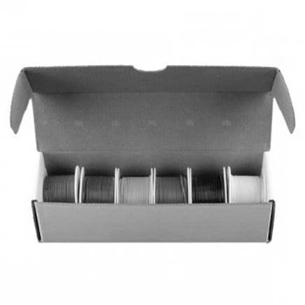
Figure 7-3. An assortment of hook-up wire spools in a dispenser box
Wire Gauges
Wire gauges are defined by the American Wire Gauge standard and are referred to as AWG sizes. With the AWG system, a higher number indicates a smaller diameter. This is historical and refers to the number of times a wire needed to be passed through a drawing die (a metal block with a hole in it) to reduce the wire to the desired diameter.
Both solid and stranded wires use the same gauge system, but there are some differences. An 18-gauge stranded wire has a larger diameter than an 18-gauge solid wire, because the spaces between the strands are not counted. Both wires will have an equivalent cross-sectional surface area of copper, however.
Table 7-1 lists the diameters and resistance for gauges 12 through 40. For electronics work, the most common type of wire encountered will be 32- to 16-gauge PVC insulated stranded wire. The most commonly used sizes seem to be 20, 22, and 24 gauge. Large diameter wire, such as 16 and 18 gauge, is sometimes used to carry large amounts of current (10A or greater) from a power supply.
|
Wire gauge |
OD (inches) |
OD (mm) |
R/1,000 ft |
R/1 km |
|
12 |
0.0808 |
2.053 |
1.588 |
5.211 |
|
14 |
0.0641 |
1.628 |
2.525 |
8.286 |
|
16 |
0.0508 |
1.291 |
4.016 |
13.17 |
|
18 |
0.0403 |
1.024 |
6.385 |
20.95 |
|
20 |
0.0320 |
0.812 |
10.15 |
33.31 |
|
22 |
0.0253 |
0.644 |
16.14 |
52.96 |
|
24 |
0.0201 |
0.511 |
25.67 |
84.22 |
|
26 |
0.0159 |
0.405 |
40.81 |
133.9 |
|
28 |
0.0126 |
0.321 |
64.90 |
212.9 |
|
30 |
0.0100 |
0.255 |
103.2 |
338.6 |
|
32 |
0.00795 |
0.202 |
164.1 |
538.3 |
|
34 |
0.00630 |
0.160 |
260.9 |
856.0 |
|
36 |
0.00500 |
0.127 |
414.8 |
1361 |
|
38 |
0.00397 |
0.101 |
659.6 |
2164 |
|
40 |
0.00314 |
0.0799 |
1049 |
3441 |
|
Table 7-1. Common AWG solid-wire gauges |
||||
Table 7-2 shows a sample of some of the more commonly encountered AWG gauges for stranded wire.
|
Wire gauge |
Stranding |
OD (inches) |
OD (mm) |
R/1,000 ft |
R/1 km |
|
16 |
7/24 |
0.060 |
1.5240 |
3.67 |
12.04 |
|
18 |
7/26 |
0.048 |
1.2192 |
5.86 |
19.23 |
|
20 |
10/30 |
0.035 |
.8890 |
10.32 |
33.86 |
|
22 |
7/30 |
0.030 |
.7620 |
14.74 |
48.36 |
|
24 |
7/32 |
0.024 |
.6096 |
23.3 |
76.44 |
|
26 |
10/36 |
0.021 |
.5445 |
41.48 |
136.09 |
|
28 |
7/36 |
0.015 |
.3810 |
64.9 |
212.92 |
|
Table 7-2. Common AWG-stranded wire gauges |
|||||
In Table 7-2 the “Stranding” column defines how the wire is organized internally. In the case of 26-gauge wire, for example, the table indicates that it comprises 10 strands of 36-gauge wire.
Note how the resistance of the wire over a given distance drops as the diameter of the wire increases (as shown in the R/1,000 and R/1 km columns for both solid and stranded wires). Also note that stranded wire conducts better (has less resistance) than solid wire of the same gauge. This is because, while the wire types might have the same cross-sectional area, the surface area of the stranded wire is greater than the solid wire.
As mentioned in Chapter 1, everything in a circuit has resistance, including the wires used to connect the circuit to a power source or another module. Since current is defined as the volume of electric charge moving through the cross-sectional area of a conductor in some unit of time, it stands to reason that the larger the cross-section area, the larger the current capacity of the conductor. This is one case where the analogy to a water pipe actually does apply fairly well. You can move a lot more water (in gallons/minute) through a 1-inch hose than you can through 1/4-inch tubing, so, by analogy, you can safely assume that 4-gauge wire will safely carry more current than 18-gauge wire.
For a realistic example, let’s say you have an application where a sensor is remotely located 250 feet or so from the rest of the equipment, and it is connected by a cable with multiple 28-gauge stranded connectors. According to Table 7-2, each conductor in the cable will have about 16 ohms of resistance over that distance. Failing to take this into account could result in bad readings or an excessive power drop to the sensor. Furthermore, because even the common (ground or neutral) return line has resistance, the sensor will tend to “float” at a voltage higher than the actual ground at the local controller, and this can introduce all kinds of nasty side effects.
Using a cable with larger conductors will help to reduce the problems, but in reality, it’s better to power a remote device with its own power source (perhaps a battery or solar panel, covered in Chapter 5) and use digital signaling and balanced twisted-pair wiring to communicate with it.Chapter 14 discusses techniques like these.
Insulation
No discussion of wire and cables would be complete without a discussion of insulation. Some time around the late 19th century, with the widespread introduction of electrical devices such as the telegraph, most wires were either bare or were wrapped with fabric or paper. In some cases, a coating of a tar-like substance or varnish was also applied to help preserve the cloth or paper insulating material.
In some historic buildings, you can still see the bare wires used to route AC power between the rooms, hopping from one ceramic insulator to the next across rafters, under floor joists, and down the inside of a wall. In smaller devices, such as early radios, the wires were often left bare and simply soldered between terminal strips or tube sockets. Electromagnetic components with tightly wound coils of wires, such as relays and solenoids, used either layers of insulating paper or wires coated with a type of varnish or shellac. Many of these types of components are still made this way today.
Times have changed, and now wires and cables are available with a variety of insulation materials. The most common type is polyvinyl chloride (PVC). This is a relatively soft, low-temperature material that is flexible and easy to strip. It does have a tendency to melt, shrink, and sometimes char when it is close to a solder joint that has been overheated during soldering. Because heavier gauge wires require more time to solder than a thinner gauge, PVC insulation on wire gauges larger than about 18 gauge can be a problem. A better choice is Teflon, but it can be difficult to strip cleanly.
Very small wire gauges, such as the fine solid wire used to do wire-wrap construction, are usually coated with Kynar, a type of polyvinylidene difluoride (PVDF). It can be annoying to strip and requires a special tool and some patience to get it right. Most manual wire-wrap tools come with a small stripper tool of some sort. But unless you need to do wire-wrap construction (which is not covered in this book) or you need to solder patch wires on a PCB, you probably won’t encounter wire-wrap wire.
Twisted Pairs
A wire is essentially an inductor (see Appendix A) and, as such, it can be subject to external interference from AC power lines, electric motors, lightning bolts, and even a nearby radio transmitter. The telescoping antenna on a portable radio is nothing more than a section of wire specifically intended to pick up the electromagnetic energy generated by a radio station. The conductive traces on a PCB can also inductively couple to one another, creating interesting and difficult-to-fix problems. Wires extending from a sensor back to a microcontroller can conduct more than just the sensor data. One technique to reduce the influence is to use twisted-pair wiring. Another involves shielding (see “Shielding”).
Twisted pairs, as the name suggests, are two wires that are twisted around each other. A twisted pair is always used for a single circuit, not two. Figure 7-4 shows both a single-channel and a multi-channel connection between two devices (device A and device B).
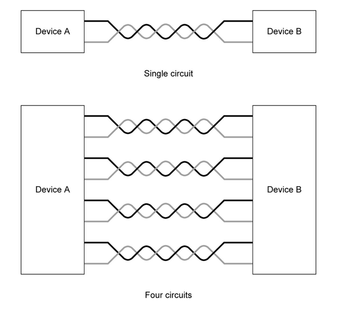
Figure 7-4. Single- and multiple-circuit twisted-pair connections
The concept of twisted pairs was invented by Alexander Graham Bell in 1881 to deal with noise on early telephone circuits. The early telephone system used existing telegraph lines, which involve just a single conductor with grounded batteries, keys, and clickers (sounders) at each end. The unshielded lines turned out to be excellent antennas for picking up things like electric street cars and noisy electrical motors.
The solution was to use twisted pairs. In a twisted-pair circuit, the wires carry the same signal with opposite polarity, so when one is positive, the other is negative. It is the difference between the wires that counts, and that difference is measured across a load at the end of the twisted pair. If external noise interacts with the pair and causes the same level of interference on both, it is ignored, because it will not induce a potential difference across the line load (this is called common-mode rejection). Chapter 14 discusses twisted-pair wiring in more detail, but the focus in this chapter is on what twisted pairs look like and how they are specified.
Figure 7-5 shows what a section of a twisted pair looks like. This was removed from a multi-conductor cable like the one shown in Figure 7-11. A twisted pair is specified in terms of wire gauge, wire type (solid or stranded), and twist rate (also called the twist pitch). In a multi-conductor cable with multiple twisted pairs, the twist rate is usually different between the pairs to minimize unwanted coupling (called cross-talk) between each of the pairs.
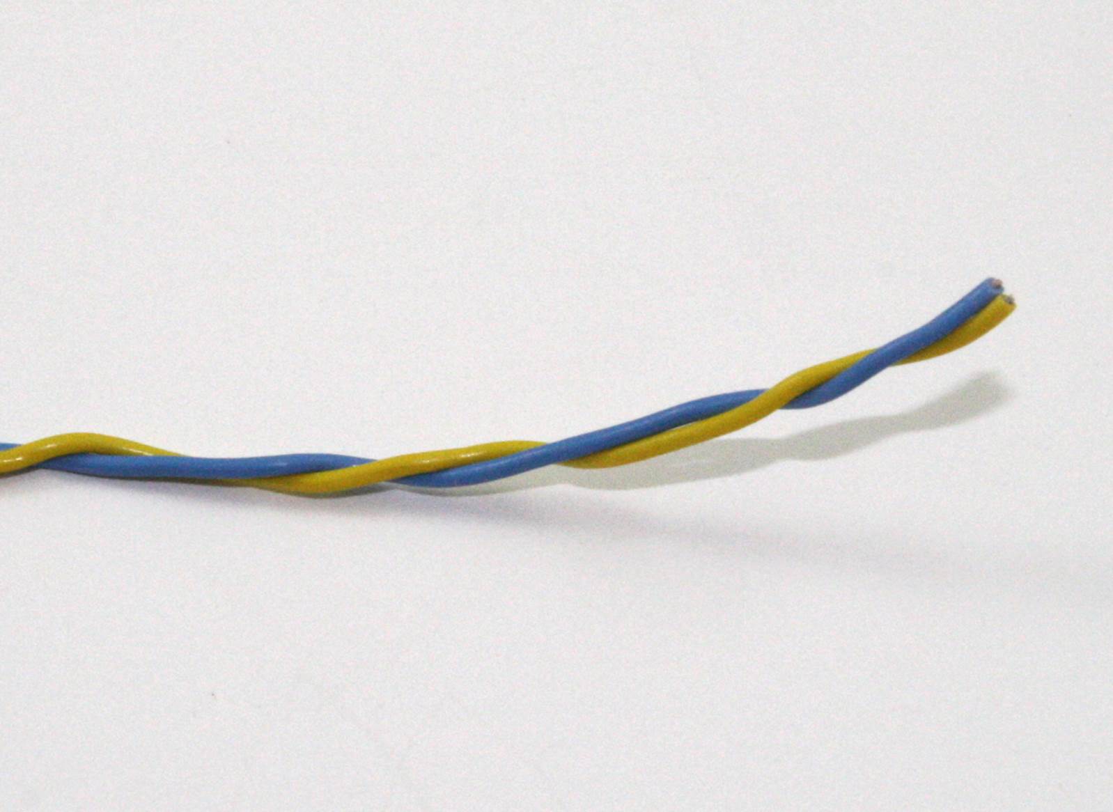
Figure 7-5. A section of twisted-pair wire from a larger cable
There is also a color code for twisted-pair wires. Typically, one member of the pair will be a solid color (blue, green, red, etc.) and the other will either be white with a stripe of the same color as its mate, or just white. Orange, blue, green, and brown are common colors found in Ethernet cables (they’re actually specified by a standard, TIA/EIA T568B). Other color schemes can be found, depending on the manufacturer and, in some cases, what the customer specifies.
Twisted-pair cables come in unshielded (UTP), shielded (STP), and foiled twisted-pair (FTP) forms. Common Ethernet cables are UTP types with four internal pairs. The cable shown in Figure 7-11 is an STP cable. In an FTP cable, each pair has conductive foil wrapped around it, and the entire cable might have an outside shield (this would be an S/FTP cable). These are sometimes found in instrumentation applications where any external interference that might skew a measurement is unacceptable.
You can make your own twisted-pair wires by simply twisting two wires. This isn’t quite as easy as it may sound, since the wires will have a tendency to end up with one wrapped around the other, instead of both twisted around each other. If you anchor the two wires at one end using something like a small vise, you can keep constant tension on them as you twist. This will help prevent wrapping.
Another way to make a twisted pair is to make a loop hook out of a piece of steel coat-hanger wire that can be used with a hand-held drill, and then drill two holes through a small block of wood large enough to pass the wire through. Cut off two lengths of wire at the length you need to twist, plus some extra (the twisting effectively shortens the wire a small amount). Knot the wires together at one end, and put the knot over the hook. Feed the loose wire ends through the holes in the wood block. While someone holds the drill and runs it at a slow speed, pull the wood block back along the wire as the drill creates the twist. Be careful to keep the wires separated before they enter the block. Figure 7-6 shows the guide board and what the homemade twist hook looks like in a drill. Figure 7-7 shows the result.
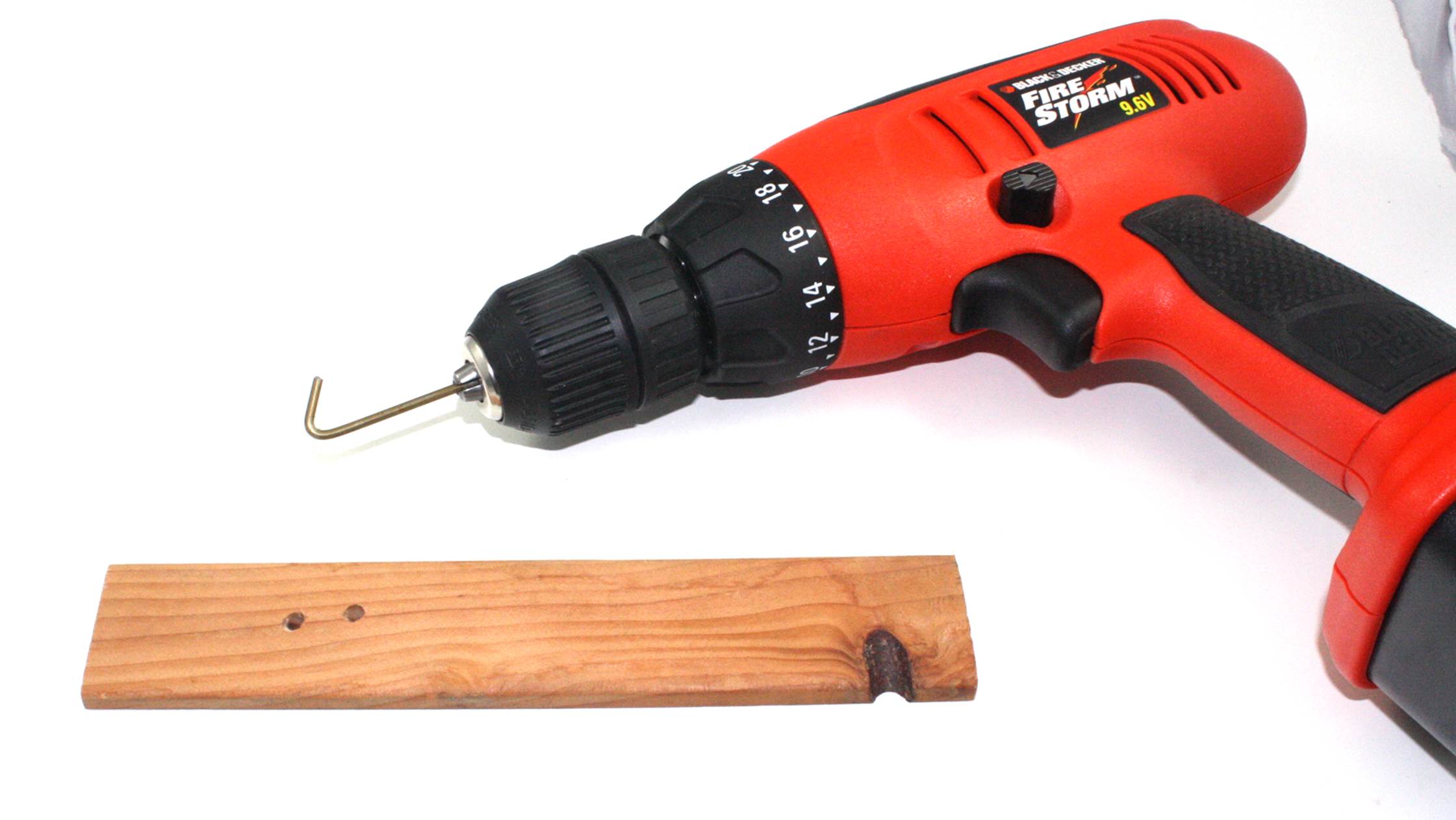
Figure 7-6. Improvised hook and guide board for making twisted-pair wire
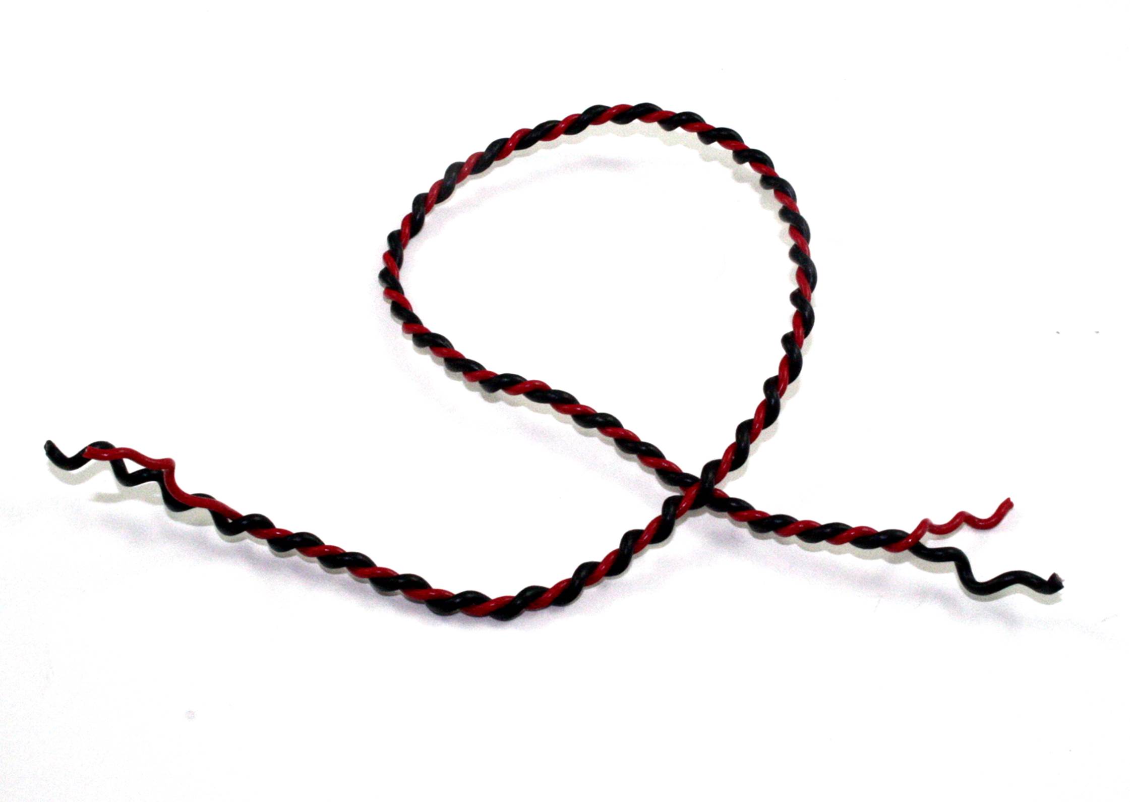
Figure 7-7. Result obtained with the improvised twist tools
Granted, the twist on the wire in Figure 7-7 might be a wee bit on the tight side, but it’s still perfectly usable. It helps to have two people to do the twisting when you’re using this technique. If you don’t have another person available to help out, or you just want to avoid the issue completely, you can purchase ready-made twisted-pair wire as just a single pair on spools in various lengths and gauges. Special bench-mounted power tools can also make twisted-pair wire, but they aren’t cheap. If you need just a little, I would suggest making it yourself. If you need a lot, buy it by the spool.
One more thing about twisted pairs: if two or more twisted pairs are run in a bundle, the degree of twist for each pair should be different. If each pair has the same degree of twist, they can cross-couple, which can create unwanted side effects. If you really need multiple pairs in a bundle, and it doesn’t have to carry much current, consider using a section of stranded CAT5 Ethernet cable. I also keep a large box of old computer and instrumentation cables on hand, and when I need a short length of multi-conductor cable, I can fish one out, lop off the old connectors, and put it to use. Then again, spools of multi-conductor twisted-pair cables are available in various lengths.
Shielding
Shielding is a way to minimize the effects of external sources of electromagnetic interference (EMI) on the conductor in a wire or cable. The concept is similar to a Faraday cage, which is a grounded conductive enclosure that prevents external electrical and electromagnetic energy from entering an enclosed space. The EMI is shunted away to ground before it can have any effect on the conductor.
The two most commonly encountered forms of wire shielding are braid and foil, and it’s not uncommon to find both in use in the same cable. Figure 7-8 shows an single conductor shielded cable, called a coaxial (or just coax) cable, which is used in video, CATV, and radio applications. Coaxial cable isn’t new; it was patented in England in 1880 by Oliver Heaviside.
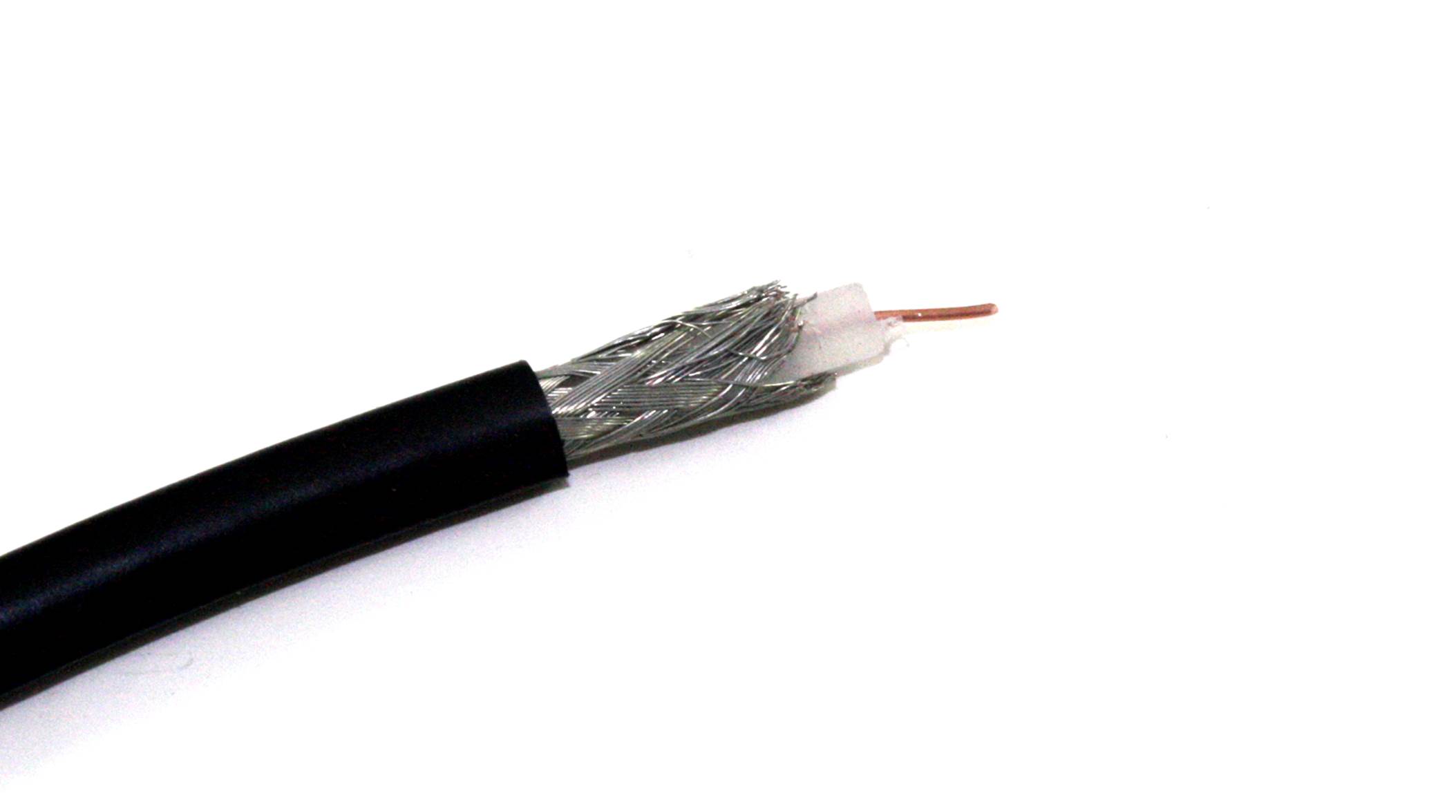
Figure 7-8. Shielded coaxial cable
Figure 7-9 diagrams the inner parts of a typical coaxial cable. The center conductor can be either solid or stranded; for RF use it’s typically solid, and for audio and video applications, a stranded conductor is often used.
Figure 7-10 shows another interesting example of a shielded cable, part of an old wireless Ethernet range extender. The cable is small-diameter coax with a connector at one end for an antenna and another at the opposite end to plug into a connector on a PCB. This was repurposed for use with a wireless data link module like the ones described in Chapter 14.
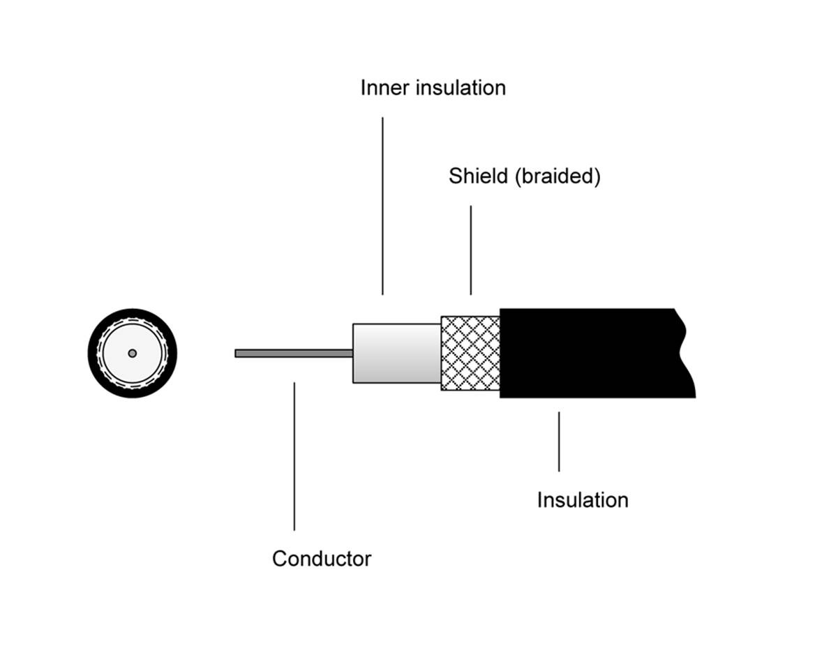
Figure 7-9. Inner construction of a shielded coaxial cable
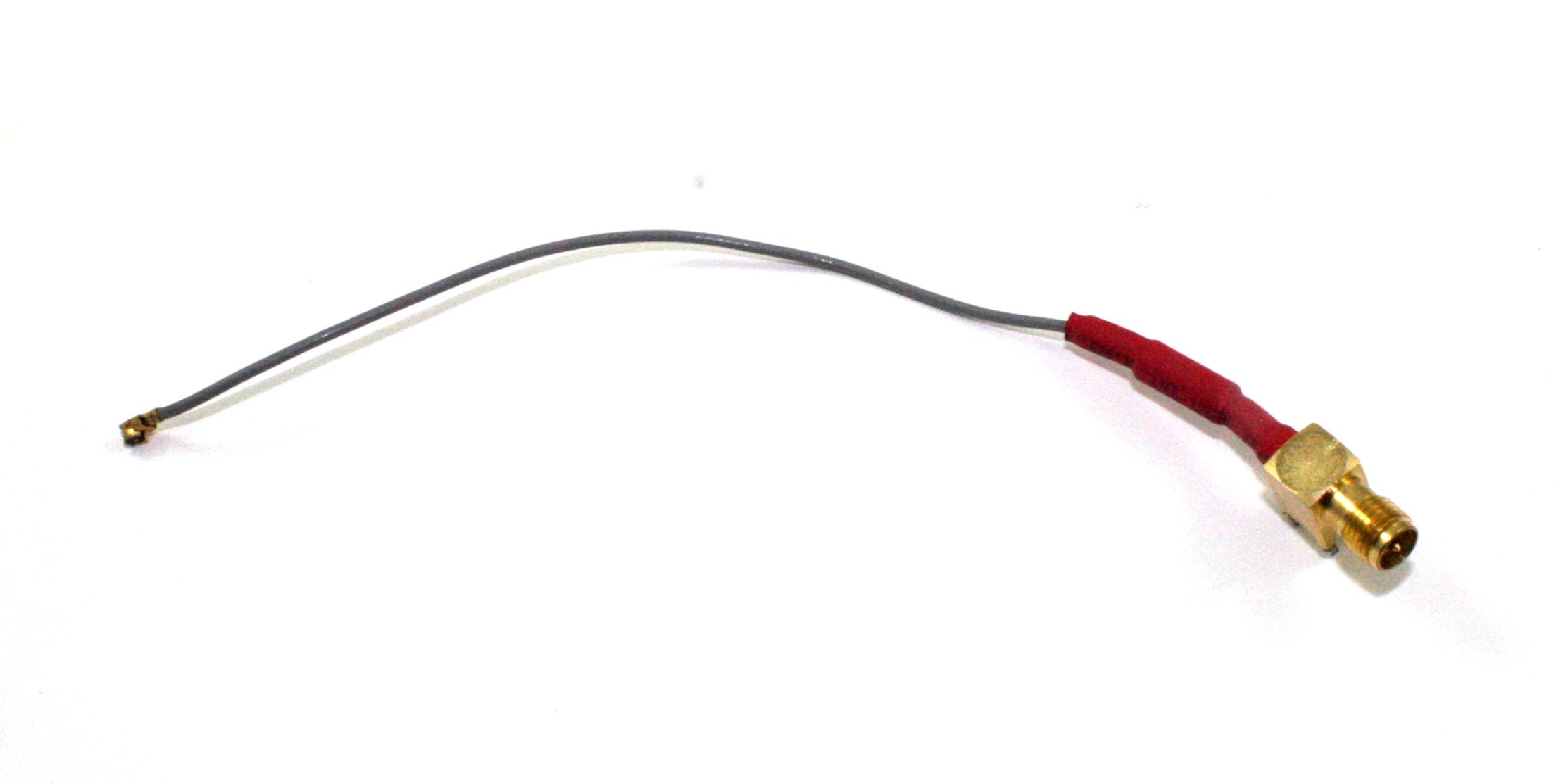
Figure 7-10. Small-diameter coaxial cable with antenna and PCB connectors attached
In some shielded cables with both a braided shield and a foil wrap, a drain wire is run along the length of the cable between the braid and the foil. This helps to ensure that the foil is grounded. The drain wire might be a solid bare wire or a bare twisted wire like the one shown in Figure 7-11. The drain wire doesn’t have to be connected so long as the braid is connected to ground, but it’s more convenient than pulling back the shield and using that as the shield ground connection.
Multi-Conductor Cables
As mentioned earlier, the term cable is usually reserved for bundles of two or more multiple conductors, or for very large single-conductor wires. This section focuses on the bundle definition.
Individual Conductors and Twisted Pairs
Some types of multi-conductor cables consist of individual wires or twisted pairs. They can be either shielded or unshielded, and the shielding might be a braid, foil, or both. Figure 7-11 shows one end of a multi-conductor cable that was used to connect a peripheral device to a PC.
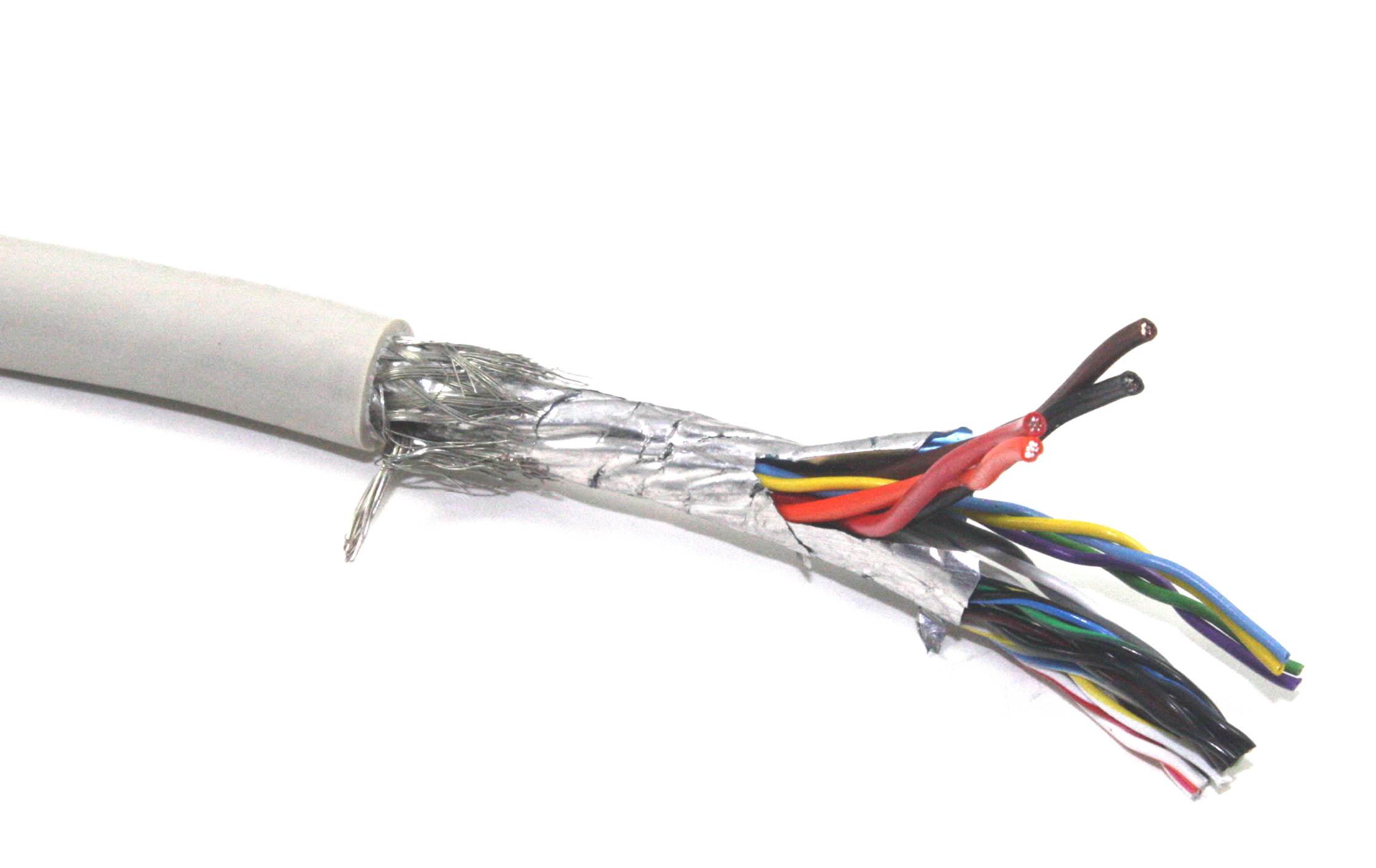
Figure 7-11. Multi-conductor shielded twisted-pair cable end
The cable shown in Figure 7-11 is a shielded twisted-pair type with both a braid and a foil shield around the entire wire bundle. The conductors consist of 10 pairs of 28-gauge stranded wires and two pairs of 20-gauge stranded wires, for a total of 24 conductors. The bare twisted strand sticking off to the side near the outer jacket insulation is the drain wire that runs along the length of the cable between the foil and the braided shield.
Unshielded multi-conductor cable is commonly used in applications where the extra protection against EMI is not necessary. Figure 7-12 shows an example of a multi-conductor cable that is suitable for DC power and control, such as connecting a remotely located relay bank or motor controller to a local microcontroller. This particular cable has two 20-gauge wires, two 22-gauge wires, and four 30-gauge wires, all stranded. There is no outer shielding.
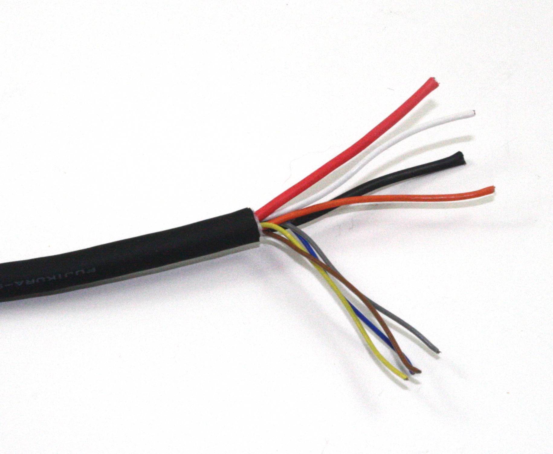
Figure 7-12. Multi-conductor unshielded cable
Ethernet cable is another type of unshielded twisted-pair multi-conductor cable. Because Ethernet uses balanced differential signaling, it is robust when it comes to rejecting external interference. So just the twisted pairs are sufficient.
Ribbon Cables
In electronics, you will often need to route a set of parallel signals from one place to another inside a device. Instead of connecting numerous single wires or using a multi-conductor cable with individual wires, you’ll find that a better solution is to use something like the ribbon cable shown in Figure 7-13. Note that part of the cable has been split and pulled back, for a reason described shortly.
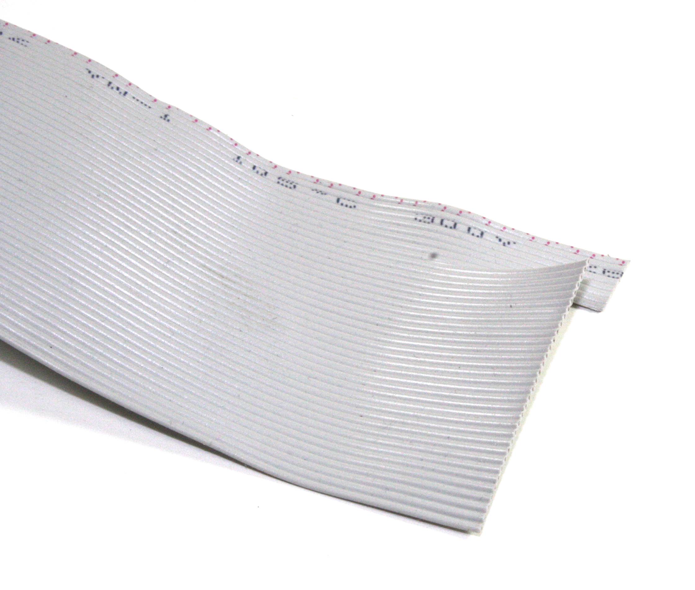
Figure 7-13. Ribbon cable
A ribbon cable (also sometimes referred to as multi-wire planar cable) consists of a set of conductors set side by side and molded into a common insulator. These flat cables come with various numbers of conductors and various conductor gauges. Cables are available with 4, 6, 8, 10, 14, 15, 16, 18, 20, 24, 25, 26, 34, 37, 40, 50, 60, 64, and 80 conductors. It just so happens that connectors are available for use with ribbon cables that have the same number of pins. These are described in “Insulation Displacement Connector”.
It is also possible to separate groups of wires in a ribbon cable into cables with some smaller number of conductors. Say, for example, you needed a ribbon cable with eight conductors, but all you have on hand is a roll of ribbon cable with 24 conductors. This is not a problem for most PVC-insulated ribbon cables. Just start the cut at the end of the larger cable for the number of conductors you want, and then pull it back. With a little care, you’ll get a nice eight-conductor ribbon cable, as shown in Figure 7-13.
The wire used in a ribbon cable is typically stranded wire in 22, 24 or 26 gauge, although some specialty cables have larger or smaller gauge wires. There are even ribbon cables with solid conductors that are intended to be soldered directly into a PCB. These would typically be used to connect two PCB modules over a short distance.
An example of where you might find solid-conductor ribbon cable is an LCD display module attached to a larger PCB. If the display will never be removed during the lifetime of the device, and the physical constraints of the packaging limit the mounting options, then a soldered solid-conductor ribbon cable might be a good choice.
As you might expect, there are special tools available to cut ribbon cable, and other tools to attach connectors. We’ll look at these a little later on.
Flex Cables
A flex cable is a relative of the ribbon cable, and is fabricated by bonding metallic conductors to the surface of a thin film and then applying another layer of film to seal the conductors inside. If you have ever opened up a cell phone, laptop computer, or portable DVD player, chances are, you’ve seen a flex cable. Figure 7-14 shows an example of a flex cable in its natural habitat. A flex cable is essentially a flexible PCB, and the cable also incorporates active components in some applications.
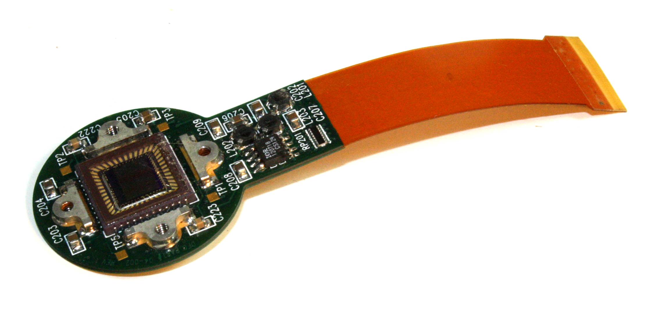
Figure 7-14. An installed flex cable
These types of cables are great for the production of miniature electronic devices, but not so good for prototypes or hacking. Still, you should probably be aware of them and have a general idea of how they are used.
Stripping Wire Insulation
Removing insulation from wire or cable isn’t always as easy as it might appear. Using a knife or wire cutters might seem like a good idea, but it’s easy to nick the underlying wire. The nick then becomes a weak point where the wire is more likely to break if flexed.
Chapter 3 describes special tools for stripping insulation from wires. It’s a good idea to invest in a couple of different types. They aren’t all that expensive and they can make the difference between having a reliable connection and a wire that breaks off during final assembly, leaving only a short stub on a connector or in a hole on a PCB.
An important point to keep in mind is how much insulation to remove. This varies, depending on how the wire will be attached. When dealing with crimped connections (see “Crimped”), you should follow the recommendations of the crimp contact manufacturer. Removing too much insulation defeats the purpose of the wire strain relief portion of the crimp contact, and leaving too much can result in no connection at all. Once a crimp contact is crimped, it cannot be easily undone.
For wires that will be soldered into a PCB, you must remove enough insulation to allow the wire to protrude through the hole in the PCB with about 1/4 inch of bare wire showing on the opposite side. Any more than this is a waste of wire. Once soldered in place, the excess wire can be removed with flush cutters (also described in Chapter 3).
As you might guess, specialty wire strippers are available for coaxial cable, ribbon cable, and multiconductor cables. These can range from cheap (and almost useless) to expensive tools designed for a production-line environment.
Figure 7-15 shows a semiautomatic wire stripping tool in action. This particular tool uses a set of blades with holes equal to specific AWG wire gauges. The main advantage of this tool is that it pulls the cut insulation away from the wire after the cut is made, and it maintains tension on the wire the whole time. It requires almost no effort to use, unlike a completely manual tool. If you elect to purchase a tool like this, also be sure to purchase an alternate blade set for other wire gauges.
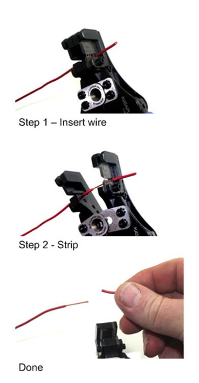
Figure 7-15. A semiautomatic wire stripping tool in action
Sometimes, however, the manual tool is the better way to go, particularly in those cases where the semiautomatic tool might not have a position for a given wire gauge. The manual tool can be continuously adjusted to accommodate a specific wire gauge. It also allows the user to feel when the tool has cut through the insulation. The semiautomatic tool has no such feedback during operation.
Connectors
It’s been said that most electronics failures are due to connectors. That may well be true, but connectors are essential, and all physical interfaces in electronic devices that aren’t soldered directly to something will utilize a connector of one sort or another. The key to success is picking the right connector for the application and then assembling it correctly.
For any given interface, there’s a connector to use for it. A look at the back of a typical desktop PC might reveal multiple types of connectors: a DB-9 for the serial port, DB-25 for the parallel printer port, a high-density DB-15 for connecting a VGA analog video monitor, an RJ-45 type jack for Ethernet, several type A USB sockets, and perhaps two or three 3.5 mm jacks for audio input and output.
Internal connections between modules and components in an electronic device often take the form of ribbon cables (see “Ribbon Cables”), coaxial cables, and bundles of wires with multi-terminal connectors at each end.
Connector Termination
There are many ways to connect wires and cables, each one designed to meet a specific need for a particular type of wire or cable. Connectors can help to make assembly more efficient and improve the maintainability of a device or system. Soldering wires directly into a circuit board, while effective, can make it difficult to disassemble for repair without causing damage, and in some cases might actually be less reliable than would be the case if the appropriate connector had been used. This is particularly true in situations where the wiring might be subjected to flexing or vibrations. The point where a wire enters a PCB or attaches to a solder-lug on a part is a flexure point, which can weaken and break over time.
We’ll start out with some descriptions of how to attach wires or PCB traces to a connector, because most of the connectors covered here are available in more than one mounting form.
Terminal Blocks
The venerable terminal block has been around for a long time, and it’s still a good option for some applications. Figure 7-16 shows what is called a barrier terminal block. Notice that each terminal position (the screws) is isolated from adjacent terminals by a low barrier ridge, hence the name.
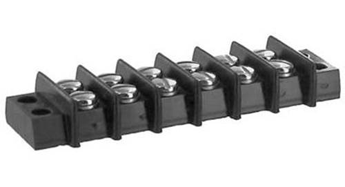
Figure 7-16. A six-position barrier terminal block
Miniature PCB mount types, such as the five-position part shown in Figure 7-17, are another variation on the terminal block. These are common on things like industrial controllers, motor driver modules for robotics, and lawn sprinkler timers. Generally, they can appear wherever there is a need to connect individual wires to a PCB without using an integrated connector of some type.
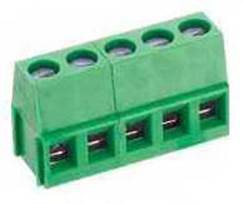
Figure 7-17. A five-position PCB-type terminal block
Insulation Displacement Connector
The Insulation Displacement Connector (IDC), shown in Figure 7-18, is a commonly used type of connector for working with small-wire-gauge ribbon cables.
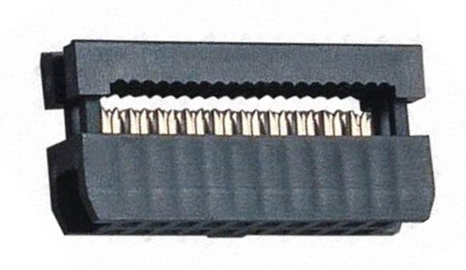
Figure 7-18. A typical IDC
An IDC generally consists of two parts: the connector body and a pressure plate. To install the connector, you insert the ribbon cable into the gap between the body and the pressure plate and compress the entire assembly using a special tool. You can also do this using a small vise, but if you are making more than just one or two cables, it’s worth it to buy the tool. Figure 7-19 shows a ribbon cable assembly with an IDC at each end.
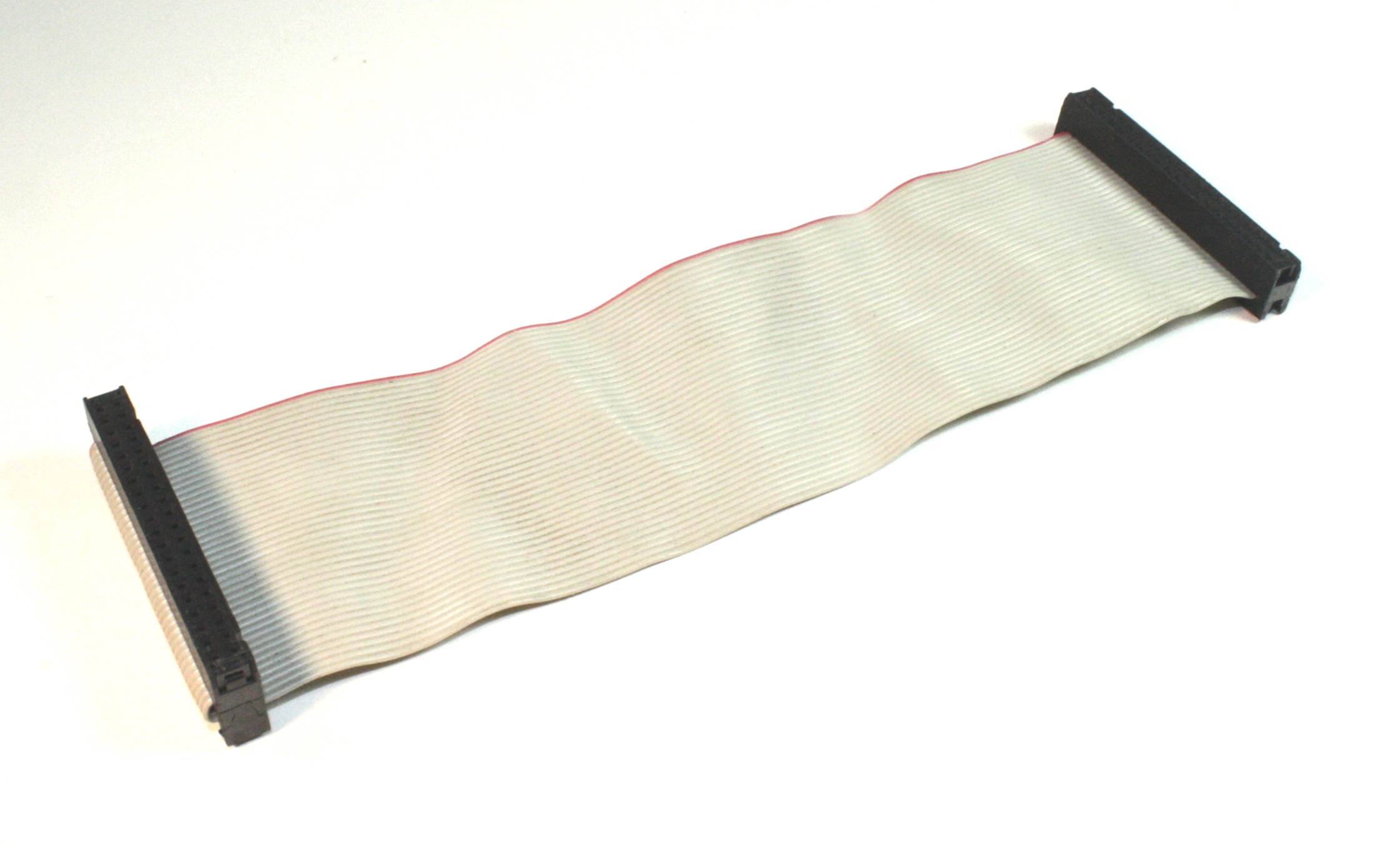
Figure 7-19. A ribbon cable assembly with IDCs at each end
IDCs are available in single-, double-, and even triple-row configurations, with a pin/socket spacing of 0.1 inch being the most common for low-voltage, small-signal applications. A mating PCB-mounted header connector is used to create board-to-board connections, as shown in Figure 7-20.
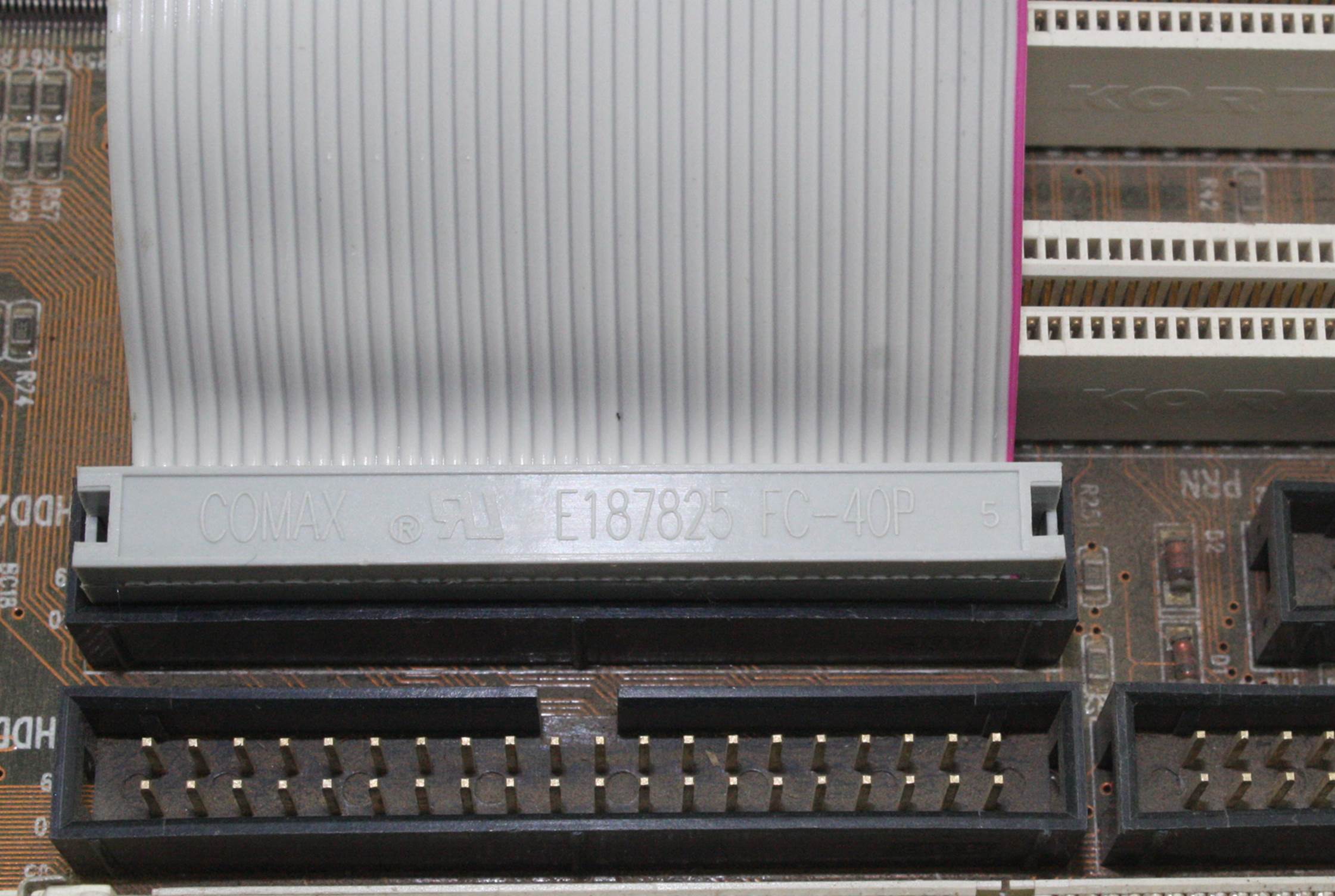
Figure 7-20. Ribbon cable with an IDC and a PCB-mounted header
IDC versions of DB-9, DB-15, DB-25, DB-37, DB-50, and HDB-15 connectors are also available, as well as the so-called Centronics-style connectors once used with printers. These are all still made today and are readily available. It is much more convenient to use an IDC DB connector than it is to solder or crimp each wire into the connector, but due to space constraints (ribbon cables and the associated connectors can take up a lot of room) and the fact that a ribbon cable is relatively easy to damage, they might not be an appropriate substitute for a soldered or crimpedconnector.
A properly assembled IDC is a fairly robust connector that lasts for many years (or even decades) in active service in an enclosed and protected environment. In fact, experience has shown that problems with IDCs don’t typically involve the ribbon cable-to-connector coupling, but instead are due to the pin sockets and solder joints that couple the IDC into a circuit module. “IDC Connectors” describes the assembly of an IDC connector.
Soldered
Some connectors are designed to be assembled using soldering techniques. These connectors typically have the rear of the pin or socket formed into a cup-like shape to accept a wire. In other cases, the connector might use insertable pins or sockets with a hole in the rear for a wire to be inserted and soldered.
Figure 7-21 shows a well-done solder connection per NASA specification NASA STD 8739.3 (marked as obsolete by NASA but still a good reference).
NASA STD 8739.3, marked as obsolete by NASA but still a good reference). The main idea is not to have an excessive amount of wire exposed after stripping the insulation, but not to have so little stripped off that it is melted or burned during soldering. “Soldered Terminals” discusses connector soldering technique, and Chapter 4 provides additional information on soldering in general.
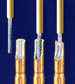
Figure 7-21. NASA-style solder-cup connection
Figure 7-22 shows a female DB-25 connector with solder-cup terminals. This is a fixed-terminal connector, meaning that the sockets (in this case) or pins (if it’s a male connector) are permanently set in the connector body when it is manufactured. Also note that the body is made of plastic, so it may melt and the contacts may shift if too much heat is applied.
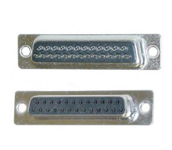
Figure 7-22. DB-25 connector with solder-cup terminals
Crimped
Connectors with crimp contacts offer the advantage of reliable and consistent connections (if done correctly), speed of assembly, and long-term durability. The downside is that there is usually an up-front cost in terms of tooling necessary to work with the crimp contacts used in the connector. In some cases, this is relatively minor, but for some connectors, the cost of the tool necessary to form the crimp connection can run into the hundreds of dollars, or even more.
Crimped contact connectors are available in DB forms, as circular connectors with anywhere from 2 to over 200 contacts, and as rectangular forms designed for use with PCBs to serve as module interconnects. They also come in a variety of sizes, from large, heavy-duty types for carrying large amounts of current to the tiny connectors found in things like DVD players.
Figure 7-23 shows two types of female crimp contacts, a barrel type (on the left) and a leaf type (on the right). Crimp contacts like these are designed to be seated in a plastic housing with one hole per contact and are typically used with a mating set of pins on a PCB (a header block or strip). They are held in place by small metal tabs that lock into a slot in the connector body, or by a plastic tab molded into the connector that captures and retains the contact.
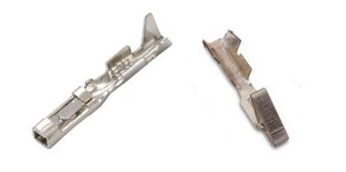
Figure 7-23. Two types of female crimp contacts for rectangular connectors
The crimp contacts used in DB and circular connectors are in the form of pins and sockets. Low-cost versions are available, but the high-reliability types are fully enclosed like the ones shown in Figure 7-24. These require a special (and rather expensive) tool to assemble correctly.
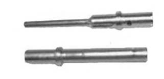
Figure 7-24. Male and female high-reliability crimp contacts
The so-called lug connectors used in automotive and industrial settings (among other places) are also a form of crimp contact. Wire lugs can be found in a number of styles, including spade lug and ring lug. The crimp tool shown in Figure 3-12 is designed specifically to work with connectors like the spade lug shown in Figure 7-25.
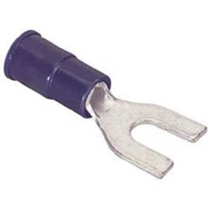
Figure 7-25. A typical spade lug
“Crimped Terminals” describes some of the tools and techniques for working with crimp connectors.
Connector Types
The previous section discussed some of the ways that connectors are connected to wires, from ribbon cables to single wires in a cable or wire bundle, using solder, crimping, and insulation displacement methods. This section looks at some of the various types of connectors that are available, keeping in mind that, for any given type, one variation might use solder, another crimping, and still another IDC approach. In the end, however, it’s still the same type of connector and should mate correctly with other connectors of that type.
Connectors come in a variety of types and styles, ranging from some that are so small that it is impossible to work with them without a low-power microscope, to others that almost need two hands to wrestle. Some consumer electronics manufacturers seem to be particularly fond of coming up with new and unique connectors for their products. Unfortunately, that means those products are incompatible with anything else. In some cases, this works out all right, as when the rest of the industry adopts the new connector and it becomes readily available. In other cases, the oddball connector will simply fade into history and perhaps end up as a curiosity on some item in a museum. Constantly changing connector types also contributes to the growing problem of electronic waste, as yesterday’s trendy gadget with the oddball connectors becomes today’s obsolete piece of junk, along with whatever once connected to it.
This section looks at the physical characteristics of common connectors that can be readily purchased from a major distributor or from your local electronics supply house. What is covered here is just the tip of a huge iceberg. There are many, many other types available, and this book can’t possibly cover them all. But rest assured, for any given application, there is probably a connector available for it, somewhere.
DB Connectors
Figure 7-26 shows the female version of a DB-9 connector, and Figure 7-27 shows the male connector. These are commonly used for RS-232 interfaces, such as those found on some older desktop PCs. Because a DB connector is relatively easy to assemble and connect to a circuit, they are also used as DC power connectors, as RS-485 connectors (another type of serial interface), and as signal interfaces for gadgets of all types.
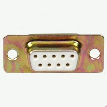
Figure 7-26. A female DB-9 connector
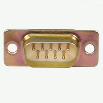
Figure 7-27. A male DB-9 connector
These connectors are not what one might call miniature types. They take up a serious amount of real estate, either in a chassis panel or on a PCB. However, if you want to put some things at the end of a long multi-conductor cable, a DB connector is an easy and rugged way to do it.
Both of the connectors in Figures 7-26 and 7-27 are panel-mount or shell types. In other words, they are designed to be bolted into a D-shaped hole in a chassis panel or other flat surface, or enclosed in a metal or plastic shell. Figure 7-28 shows a DB-9 connector and shell assembly.Internally, the DB connector might have solder-cup connections (like the part shown in Figure 7-22), crimped sockets (since this is a female connector), or even be an IDC type. “Connector Backshells” covers backshell assembly.
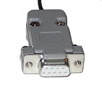
Figure 7-28. DB-9 connector with backshell
DB connectors are readily available with 9, 25, 37, and 50 pins. A high-density version, the HDB-15, is commonly used for analog computer monitors and is still found on the back of many desktop PCs. DB connectors are also available in PCB mounting styles, both right-angle and vertical (upright) mount.
Figure 7-29 shows pin numbering for a DB-9 connector. Notice that the pins are reversed between the male and female connectors when viewed from the face of the connector.
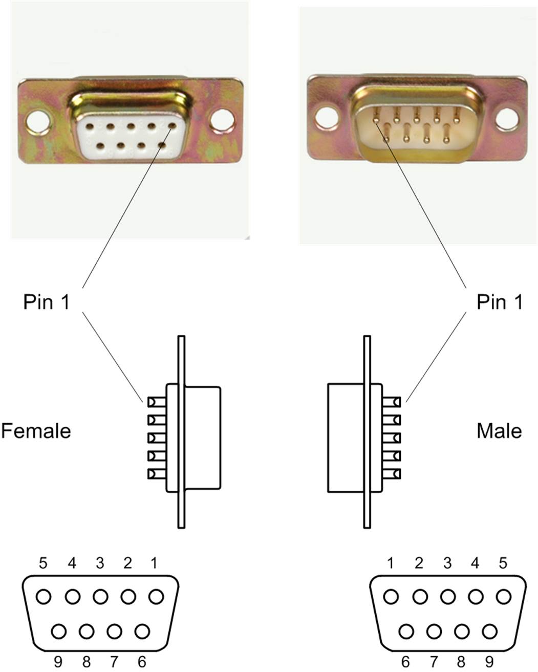
Figure 7-29. Pin numbering for male and female DB-9 connectors
If size isn’t an issue, or you just want to put a connector on something while you are prototyping it, then a DB type can be a reasonable choice. They are handy for situations where a significant amount of current might be flowing, such as in the battery-charging circuit for a robot. Use four of a DB-9’s pins for positive and the other four for the negative, with the ninth pin serving as a frame (earth) ground, and you can push many amps through the connector (between 5 and 10 amps per pin at 5 to 12V DC, depending on the type of pins and sockets used—solid machined pins can handle more current than stamped pins).
PCB Edge Connectors
Connecting one PCB to another can be accomplished in a variety of ways, but it might not be a good idea to use soldered connections to do the job. A connector of some type makes it much easier to disconnect a PCB and replace it if something breaks, or just take it out and work on it.
When printed circuit boards first started to appear about 50 years ago, there were some interesting notions about how they should be connected to the other modules in a system. After various methods were tried, a popular trend emerged that utilized the copper traces on the PCB itself as part of the connector. These special traces are colloquially called fingers, and they were laid out with the correct width and spacing to mate with what is known as an edge connector. A thin layer of gold is usually applied to help improve reliability.
Figure 7-30 shows a PCI (peripheral component interconnect) riser that has both connector fingers and a socket for a PCI circuit board. This type of add-on circuit board is commonly found in 1U (1.75 inches high) computer servers and allows for an additional board to be installed in the limited height available by orienting it sideways.
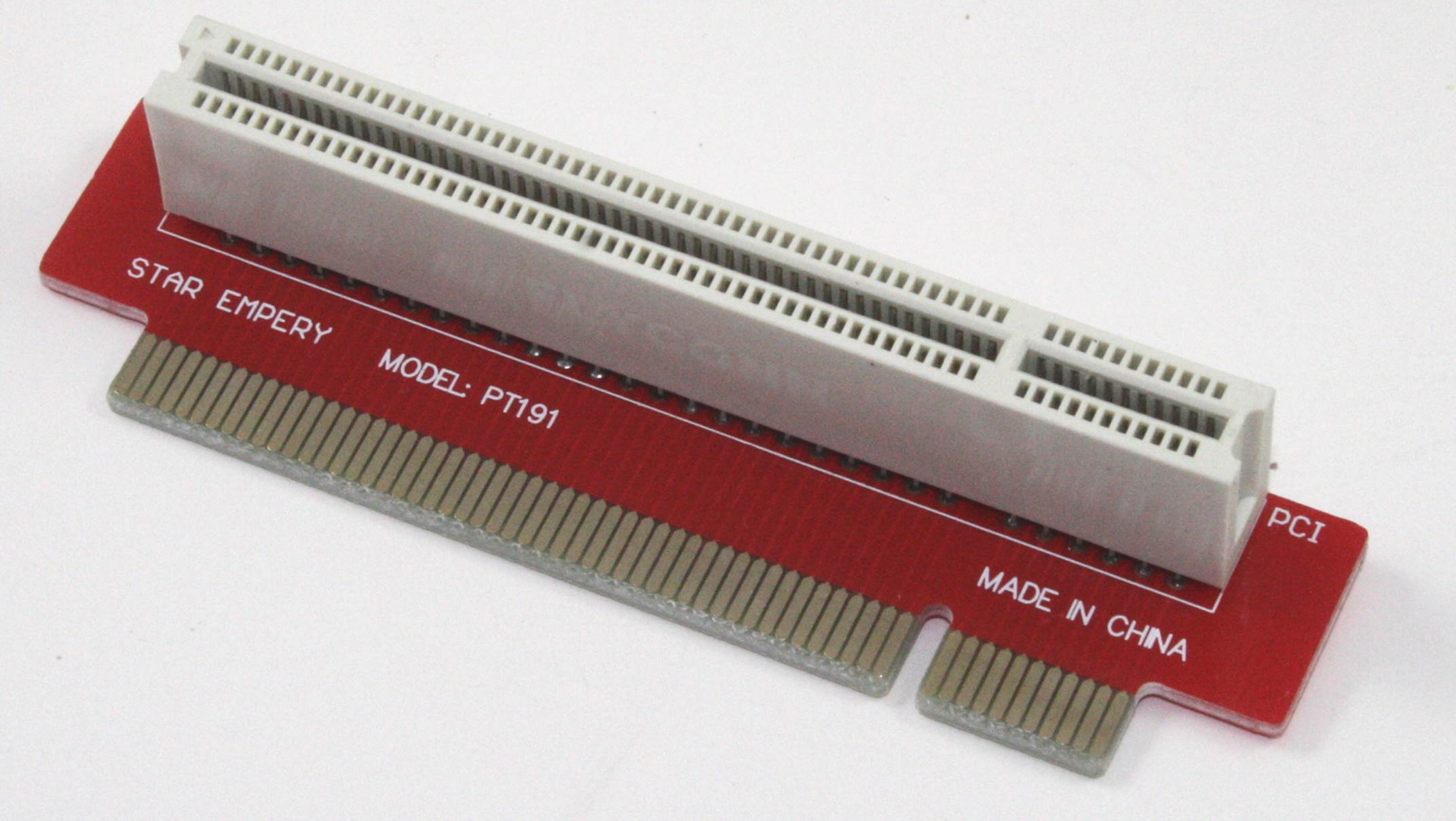
Figure 7-30. Connector socket and connector finger traces on a PCI riser PCB
The edge connector is still in use today, and it offers the advantage of simplicity and reduced cost, since only one actual connector is required, with the PCB itself serving as the other part. There are even edge connectors with IDC termination available so that you can use a ribbon cable to connect to a PCB using the built-in connection fingers. While this might sound a bit strange, it was once quite common.
One downside to the ribbon cable and edge connector approach is that the connector holds onto the PCB by friction, so it must be strapped or otherwise restrained to keep it from working off due to vibration. Edge connectors can also suffer from wear and corrosion, and over time they might start to exhibit problems. Occasionally cleaning the PCB fingers with a cotton swab and alcohol was once a common ritual for service technicians. Today, special chemicals are available that will lift off corrosion and help restore the surface without requiring excessive friction that might wear off the gold plating.
Pin Headers and Sockets
Another common type of PCB connector uses set of pin or socket contacts spaced at regular intervals. Figure 7-31 shows an example of both male and female versions of these types of connectors. A spacing (or pitch) of 0.1 inch (2.54 millimeters) is common, and other pitch spacings are also available, including 0.4 millimeters, 0.5 millimeters, and 1 millimeter. For a 0.1-inch pitch connector, the posts (pins) have a square cross-section of 0.025 inches (0.635 millimeters) per side.
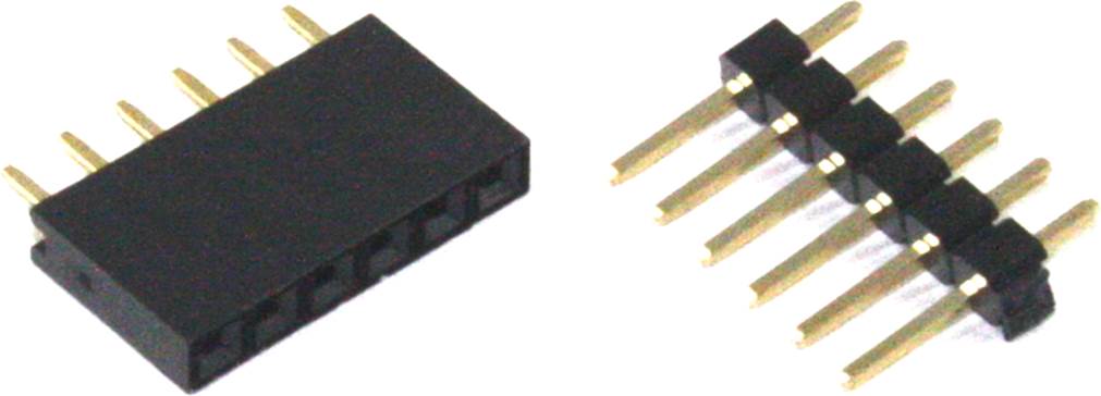
Figure 7-31. Examples of 0.1” pitch headers
The use of pins and sockets to make connections is very old, and over the years, the concept has been extended to a multitude of shapes, sizes, and styles. For PCB applications, there are IC sockets that accept the pins of DIP-style IC packages (see Chapter 9 for IC package types); strips of machined sockets for the same purpose that will also work with crimp-on pins of the correct diameter; header blocks with one, two, or three rows of either pins or receptacle contacts; housings designed to couple with IDC connectors; and housings designed to accept crimp-on contacts with space for anywhere from 1 to 40 or more positions. Figure 7-32 shows a dual-row 16-position header mounted on a PCB.
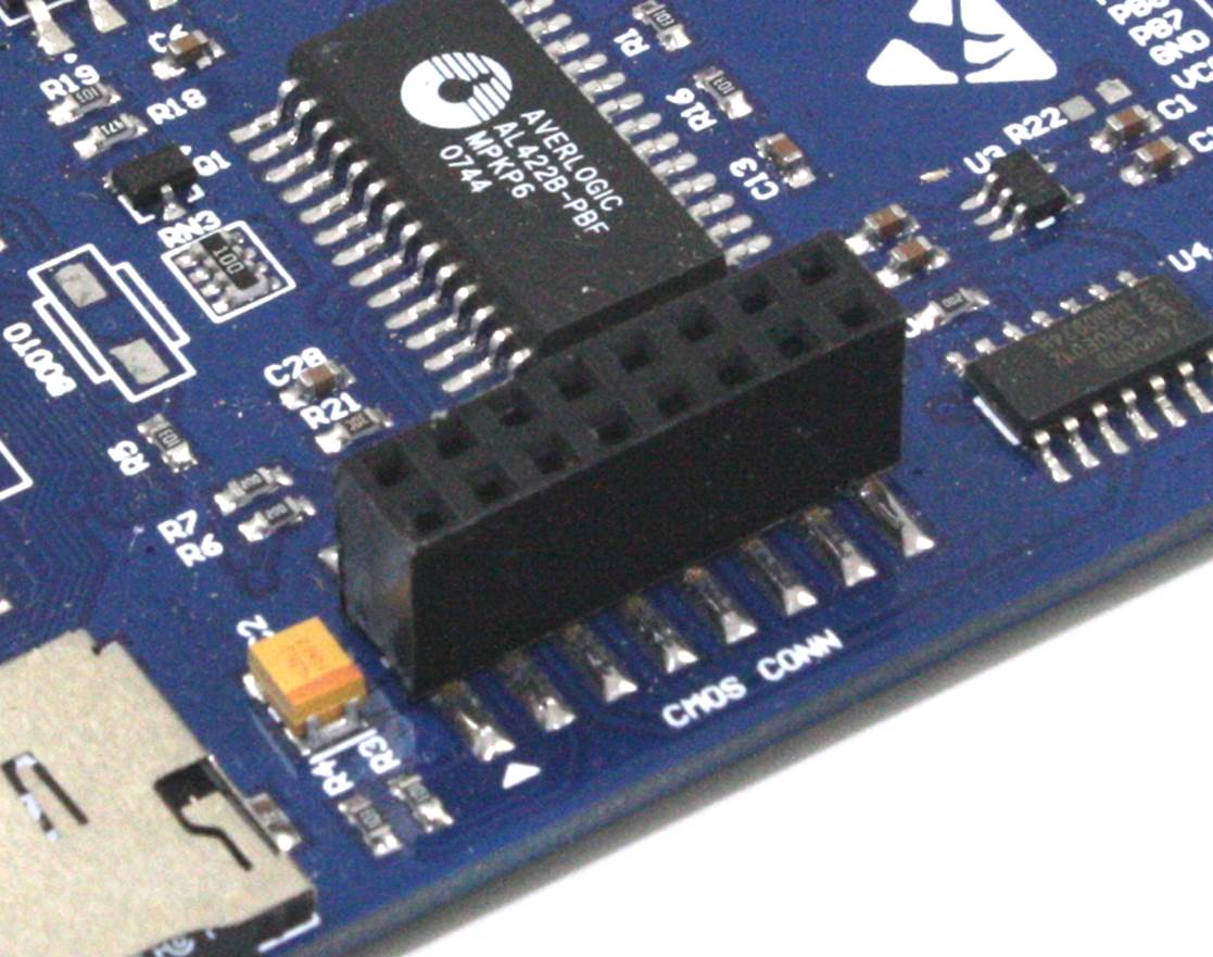
Figure 7-32. Dual-row 0.1” pitch header mounted on a PCB
Connections made between cables are often referred to as in-line, and the pin-and-socket concept can also be found in the in-line connectors used in some types of vehicle wiring harnesses, the power wiring inside an assembly line machine, and in the precision high-density circular connectors used in aerospace applications. Some examples of the different types of crimped connectors used for pin-and-socket applications appeared earlier in “Crimped”.
An odd thing here is that, even though this is an old concept, no consistent naming conventions appear to be in use. One supplier might call a part a socket strip, while another might refer to a similar part as a female header. The receiving contact is sometimes called a socket, a female contact, or a crimp terminal, depending on how the part is manufactured and how it is intended to be used (soldered directly to a PCB or crimped onto a wire). A pin contact is almost always called a pin, however, although it will sometimes be referred to as a male contact.
For our purposes, I’ll refer to the pin contacts as pins and the receptacle contacts as socket contacts. Rows of either type in a molded plastic block or housing will be called either a pin or socket header, as appropriate.
Figure 7-33 shows how these types of connectors are assembled. In this case, the headers and housings have a single row of eight contact positions, but they are also available in other patterns, from a single contact to three rows of contacts with up to 40 or more positions per row.
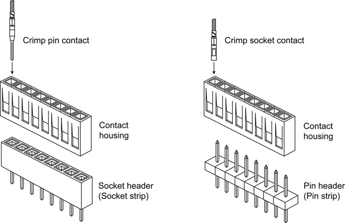
Figure 7-33. Pin and socket connectors and headers
Note that, while it’s not shown in Figure 7-33, a pin header strip will mate with a socket header, which can be used for board-to-board interconnects. You can find these on things like Arduino boards, for example.
Figure 7-34 shows another style of pin-and-socket connector. These are intended for connecting wiring to a PCB, as shown here. Notice the upright tab on the pin strip. This is used to grip the socket shell, providing a more reliable interface than you would get by just pushing a socket onto the pins.
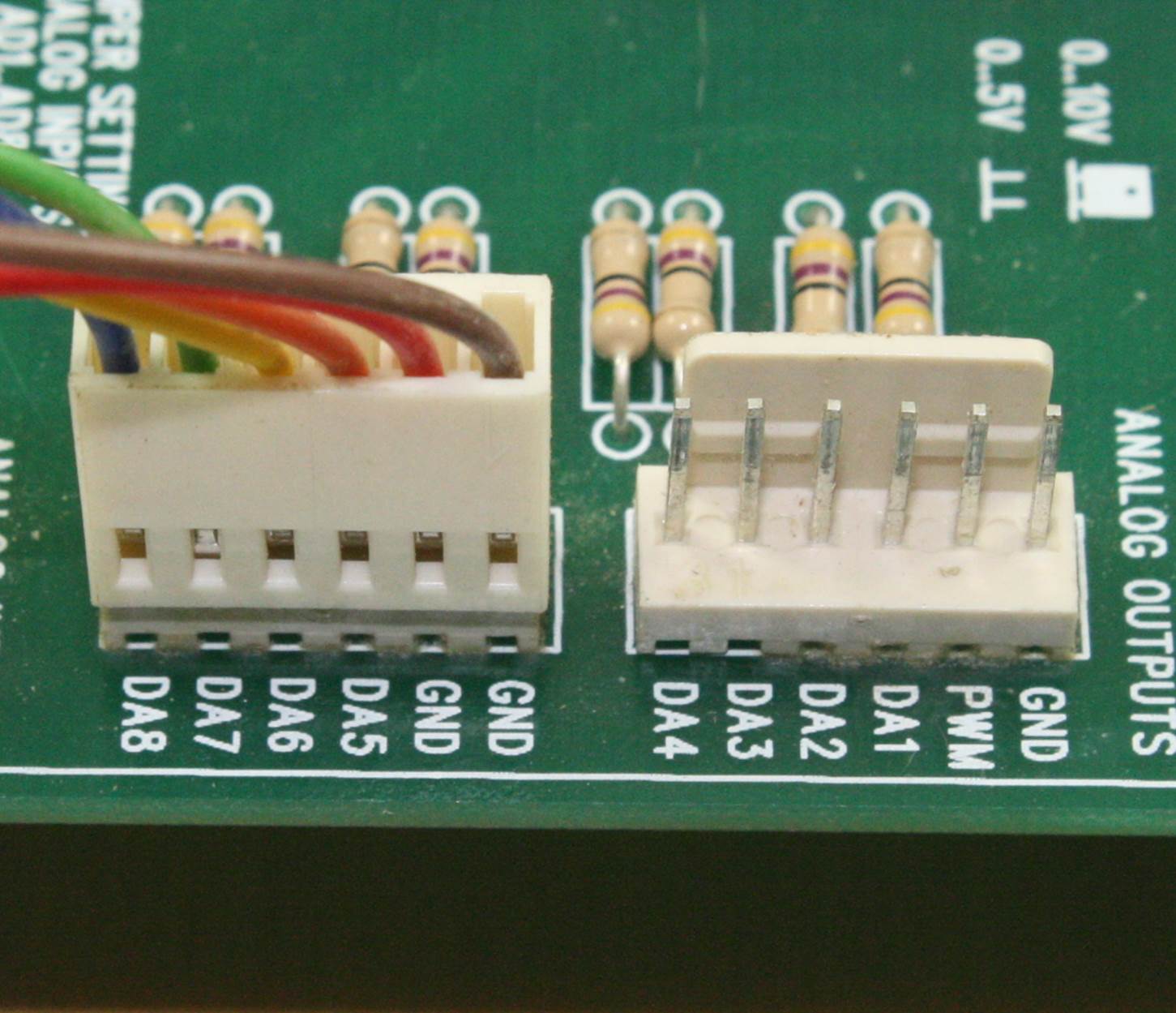
Figure 7-34. PCB interconnect using pin-and-socket headers
The idea of using a part of the connector as a retainer can be extended to create pin-and-socket assemblies that mate so tightly that a tool is necessary to release the plastic latch (or latches, in some cases). Connectors with a heavy-duty latching mechanism are found, for example, in automobiles, soda dispensing machines, and in some PCs for the motherboard power cables.
These types of connectors are designed for use with individual wires, not ribbon cables. Although a pin header like the one in Figure 7-32 can be used with a ribbon cable IDC, special-purpose headers are also available, like the one shown in Figure 7-20.
Other types of connectors for use with PCBs are available from multiple sources, such as Molex, Hirose, TE (formerly Tyco/AMP), and others. Some are miniaturized and require special tooling to assemble. Some are used for cable-to-cable connections, while others are intended for use as miniature PCB interconnects. There are through-hole types available, and others for surface-mount applications. Parts and tools are available from major distributors such as Allied, Digikey, Mouser, and Newark, so it’s worthwhile to look through what’s available. Lastly, make a point to disassemble an old portable CD player or digital camera and look at how things are connected. There’s no better way to find ideas than to look at how someone else solved a similar problem.
2.5 and 3.5 mm Jacks and Plugs
Anyone who has ever used earbuds to listen to music with an MP3 player knows what a 3.5 mm stereo plug looks like. Some devices, like cell phones, use the smaller 2.5 mm version for things like a hands-free headset.
These plugs, and the matching jacks, are common and readily available. The jacks come in both panel-mount and PCB-mount styles, and some have a threaded barrel with a nut to hold the jack in place. Soldering either the jack or the plug can be a challenge, however. The plugs can be particularly troublesome, as they don’t have much room inside the shell. The solder connections must be as minimal as possible and still be reliable, and the small size limits the size of the wire that can be used.
Another potential drawback to small plugs like these is the limited number of circuits available. A basic plug has only a tip and ring, as shown in Figure 7-35.
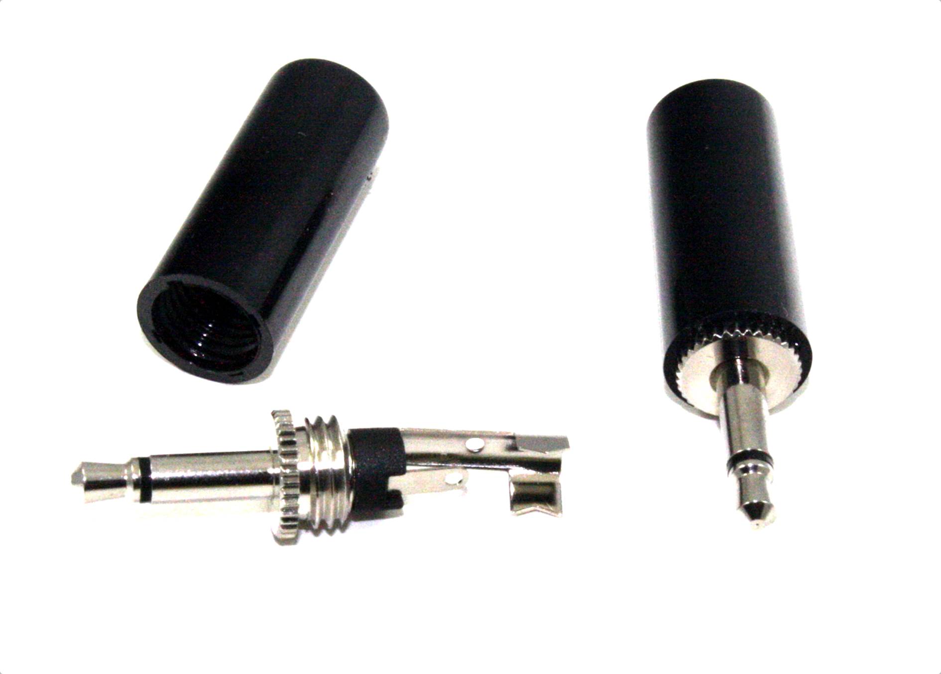
Figure 7-35. Typical small (3.5 mm) two-contact plug
A stereo plug is a three-contact version, like the plug shown in Figure 7-36. With this type of plug, there are two possible active circuits and a ground return. Although typically used for stereo audio applications, there is nothing that would prevent it from being used for another purpose, provided that the voltage and current are within the capabilities of both the connector and the wire used with it.
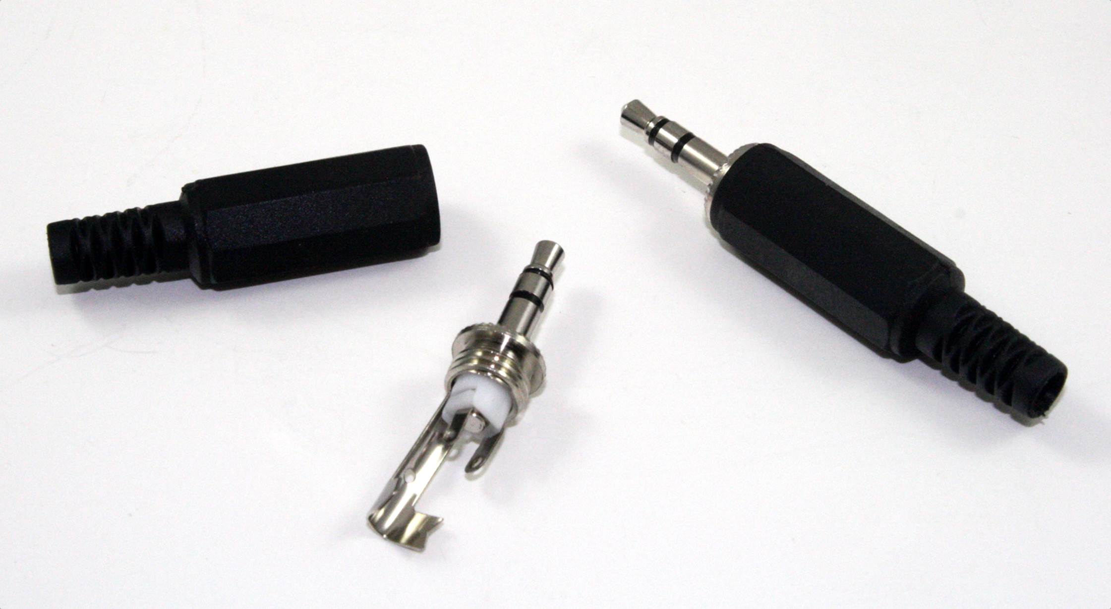
Figure 7-36. A three-contact (stereo) 3.5 mm plug
If you need to be able to connect headphones to a device, or if you want an easy way to implement patch cables, 3.5 mm plugs and jacks are a good solution. They are not really a good idea for supplying power, since there is a chance that a temporary short might occur when the plug is inserted or removed.
USB Connectors
In Universal Serial Bus (USB) terminology, there are hosts and devices. USB employs a master-servant type of communications protocol, where only the host can initiate a conversation and the device only responds (this is covered in Chapter 14). Hosts and devices have unique connector types, the shapes and sizes of which are defined by the USB standards.
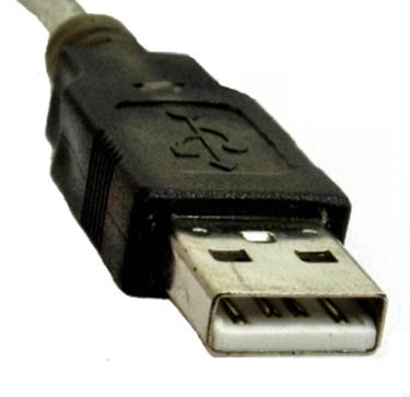
All USB connectors have four contacts: two for the data signals (D+ and D–) and the other two for power (+5V) and ground. Typically, these are premolded, so (hopefully) you won’t need to assemble any of them. What you should be aware of are the four different types of connectors defined by the USB standard and shown in Table 7-3.
|
Type |
Appearance |
Application |
|
Type A |
|
Used primarily at the host or controller end of a USB connection. |
|
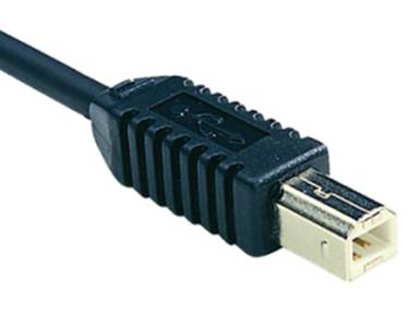
Type B |
|
Used primarily on servant devices such as USB hubs, printers, and cameras. |
|
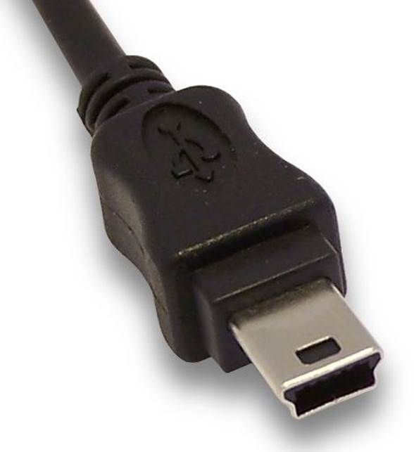
Mini |
|
Commonly found on consumer digital devices such as cameras, toys, and some cell phones. |
|
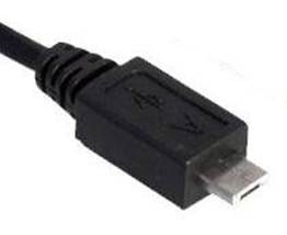
Micro |
|
Similar to the mini USB connector but slimmer. Designed to be more resistant to wear than the mini type. |
|
Table 7-3. USB connector types |
||
Type A connectors are common on desktop and notebook PCs that act as hosts. Some external devices use the B type, although the mini and micro forms are becoming common as devices (such as cell phones, miniature cameras, single-board computers, and toys) shrink in size. Avoid the temptation to create your own USB connector, because once you go down that path, you’ll also need to make custom cables. It’s easier, and in the long run cheaper, to just buy the PCB-mount connectors and pre-made cables.
Receptacles for all of the connector types come in PCB-mount styles, both through-hole and surface mount. Figure 7-37 shows both type A and type B receptacles with through-hole leads.
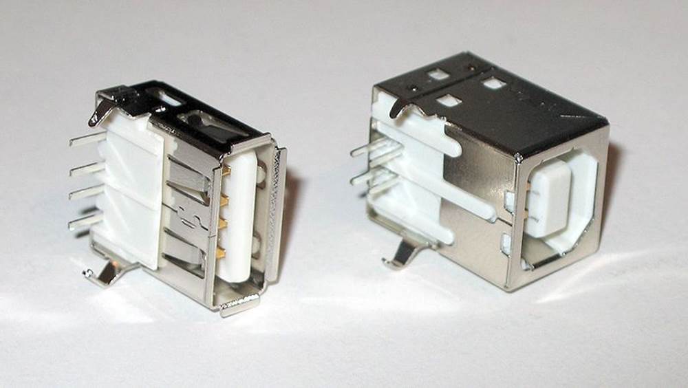
Figure 7-37. PCB-mounted type A and B USB receptacles
A word of caution: it is probably not a good idea to use a USB connector for anything other than a USB interface. While the venerable DB-9 and DB-25 connectors have been used for a variety of things besides RS-232 serial interfaces, USB connectors are part of an industry-accepted standard. A mini USB receptacle implies that someone could plug it into a PC and expect it to work. If the connector isn’t wired for standard USB, the result could be disappointing (or worse).
Ethernet Connectors
Ethernet connectors have evolved over the years, from so-called vampire taps and tubular twist-lock coaxial connectors (known as BNC types) and shielded coaxial cable strung from machine to machine, to the present-day use of 8P8C connectors, also referred to as an RJ45 type. Most Ethernet networks are arranged in what is called a star configuration, where a switch or hub distributes the signals to attached machines and other switches and hubs. An Ethernet switch—as its name implies—switches, or routes, the data between the primary cable to the connected PCs or other devices. The other devices can include Arduino or Raspberry Pi boards with Ethernet connectors, test equipment (newer types), video cameras, and even kitchen appliances.
Attaching something to an Ethernet network is usually as simple as plugging in a cable. Figure 7-38 shows an Ethernet cable with an RJ45 attached and a PCB module with the mating receptacle.
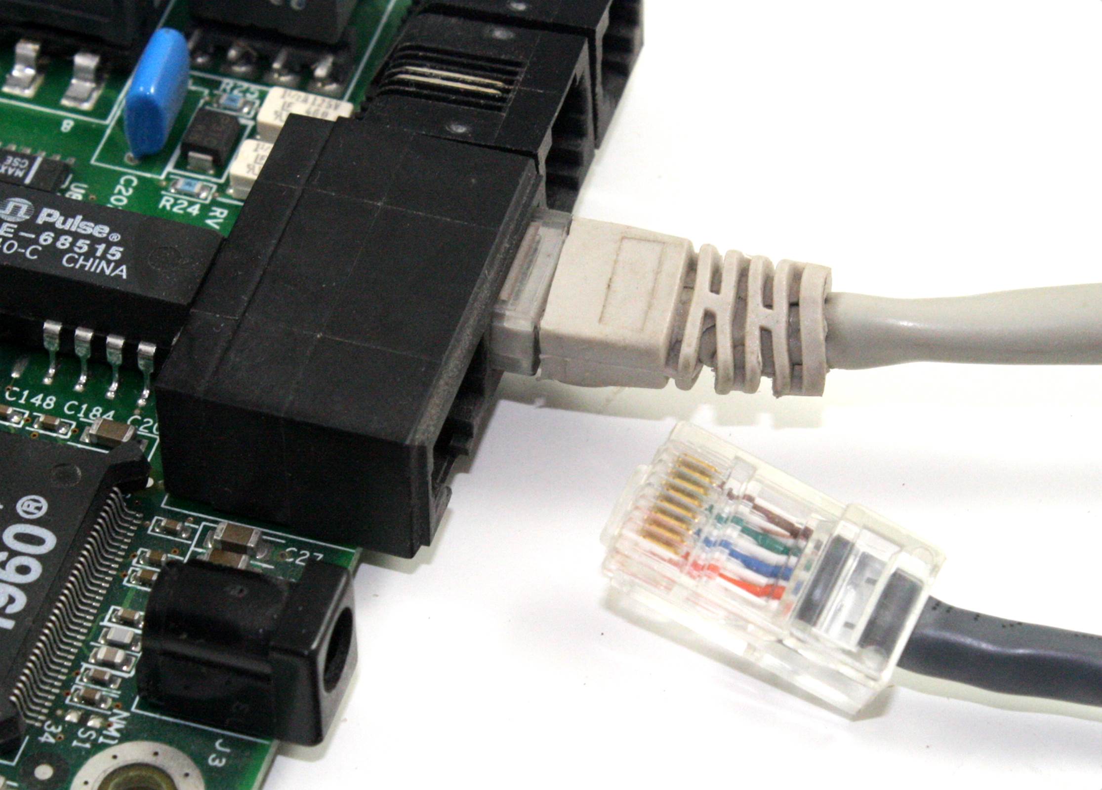
Figure 7-38. RJ45 Ethernet connector and receptacle
The same caution given for repurposing a USB connector also applies to an RJ45 connector. When someone encounters an RJ45, she expects it to be an Ethernet connection, not a DC power or control signal connection. You can devise your own connectors for Ethernet, but avoid using the standard RJ45 types for anything but Ethernet.
Assembling Connectors
Assembling a connector correctly is essential for durability and reliability. It is well known that a large percentage of failures in electronic devices are the result of connector failures, so getting it right from the outset can eliminate a lot of annoyance later on.
Soldered Terminals
Connectors available with solder terminals include the DB family, circular connectors (not covered here), 3.5-millimeter and 2.5-millimeter audio jacks, and 1/4-inch jacks like those used for musical instruments (also not covered here). Connectors such as Ethernet and USB typically come as complete parts that just need to be soldered to a PCB, or crimped onto a suitable cable in the case of an RJ45 connector.
As discussed in Chapter 4, the idea behind soldering is to heat both the connector and the wire with the tip of the iron so that the solder will flow smoothly onto both. In some cases, this might be tricky, since inexpensive connectors might have an injection-molded plastic body. If the soldering iron is in contact with the pin for too long, it might melt the surrounding plastic and ruin the connector.
The key is to remove the iron immediately once the solder has flowed into the connector’s cup. Blowing on it gently to cool it down can help reduce the risk of melting the plastic of the connector body around the pin. Placing the connector in a small vise or using a “helping hand” fixture (both described in Chapter 3) can help to avoid some aggravation. It also sometimes helps to apply a small amount of paste flux prior to soldering. This will help lift off contamination from the wire, the contact, or both, and the solder might flow more smoothly. Just be sure to clean off any flux residue after the soldering is complete, and make sure not to get the flux residue on the contact pins or in the socket contacts.
Crimped Terminals
When you are assembling a connector with crimped contacts, the first step is to crimp the wires into the contacts and crimp them securely, one at a time. Figure 7-39 shows three of the four main parts of a crimp contact (the fourth is the barrel or pin that mates with a matching contact or header pin).
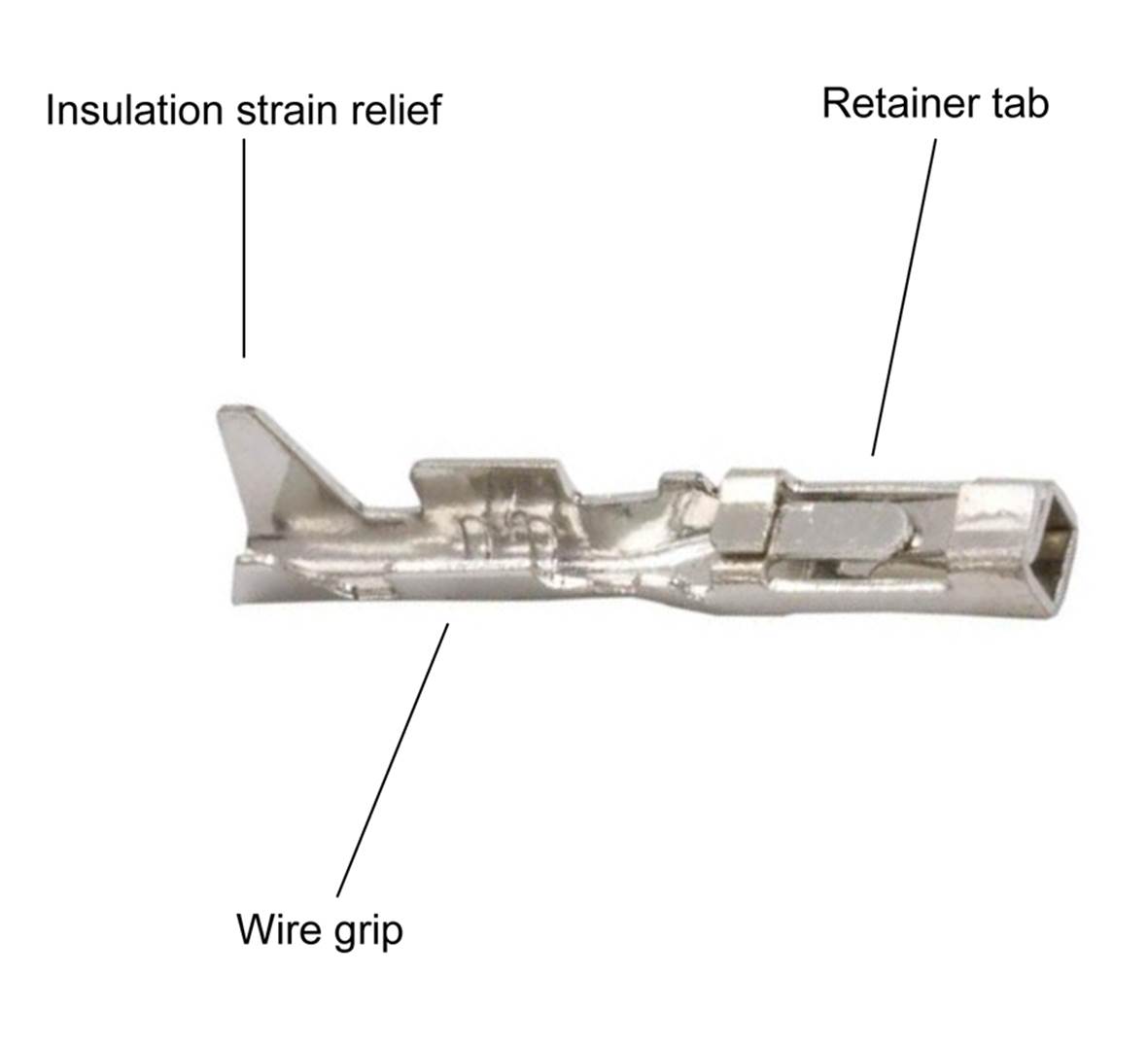
Figure 7-39. Main parts of a crimp contact
As shown in Figure 7-40, the wire is gripped in two locations: the insulation strain relief and the wire grip that makes the electrical connection. The strain relief is essential, as it helps to prevent the wire from flexing and possibly breaking off at the wire grip point.
The key to making a good contact assembly is paying attention to the amount of insulation removed from the wire. Too much, and the strain relief won’t grip correctly; too little, and the wire grip section won’t be able to make a solid electrical connection.
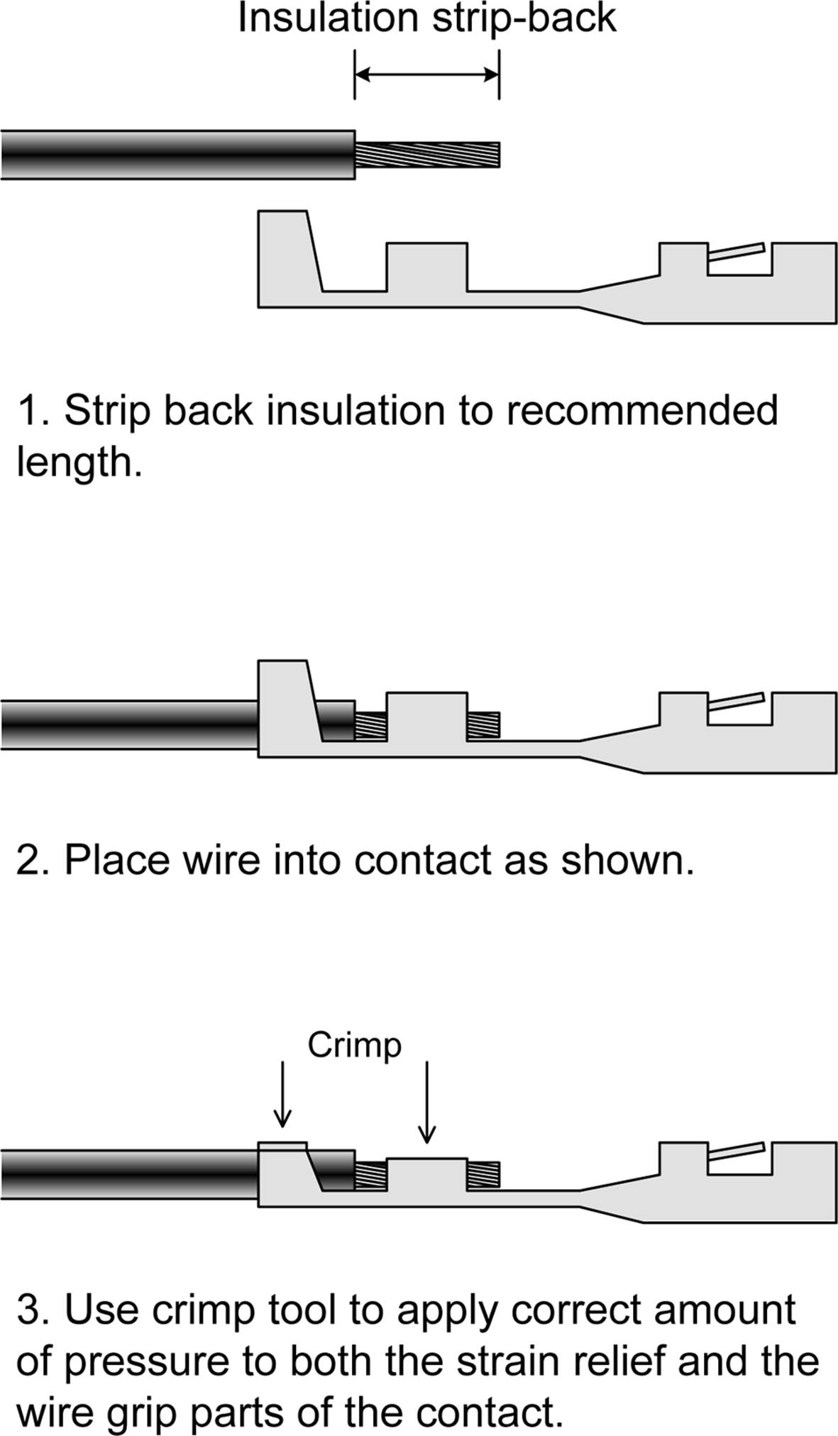
Figure 7-40. Diagram of a correctly assembled crimp contact
Contacts that are designed to be crimped need a tool made specifically for that type of contact. Pliers or a lug crimper like the ones found at an auto supply store simply won’t work correctly. You might be able to get something that sort of works, but it probably won’t be as neat and reliable as it would be if the correct tool were used instead.
The tool for the job is something like the one shown in Figure 7-41 (described in “Crimping Tools”). This particular tool has provisions for two different contact sizes, and it’s used primarily for DB connector pin-and-socket contacts.
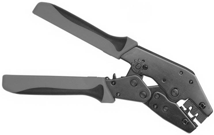
Figure 7-41. A multi-size contact crimping tool for small contacts
The crimp locations in the tool (or die, as they are sometimes called) actually have two areas for each that apply pressure to both the strain relief and the wire grip parts of the contact, and at the same time the fingers on the contact are rolled over the wire. The tool is ratcheted, so it can apply a significant amount of force without excessive hand force. It costs about $40.
In some cases, you might need a crimped contact on a single wire, but not an entire connector body full of them. This is often the case when you’re working with things like an Arduino. You can purchase bundles of premade jumper wires, or you can make them yourself. If you do elect to make your own, remember to slip a piece of heatshrink tubing over the contact after it’s been crimped, to prevent shorts and possible damage to the wire.
Connector Backshells
Some connectors, the DB series in particular, can be assembled with what is called a backshell. Figure 7-42 shows the various bits and pieces that make up a backshell like the one shown in Figure 7-28. A backshell protects both the connector and the wiring by covering the terminals and providing strain relief for the cable or wires attached to the connector.
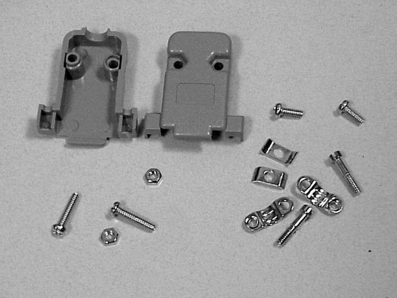
Figure 7-42. The parts that make up a DB-9 connector backshell
The assembly is straightforward: two screws with matching nuts hold the shell together, two more screws with retainers are used to tighten the connector against a matching connector, and two threaded clamp straps and matching screws form the cable strain relief. The DB-9 connector seats into the front of the shell, and once the shell is assembled, the connector will sit securely with minimal movement (if any).
IDC Connectors
Figure 7-44 shows an IDC before and after assembly. In some cases, there is also an additional, strap-like part that holds the ribbon cable to the pressure plate to provide strain relief and prevent the cable from working loose. The strain relief strap is attached to the connector after the ribbon cable has been inserted and clamped.
An IDC works by forcing metal blades with slits through the insulation of the ribbon cable, with one blade per wire in the cable. The conductors in the ribbon cable are forced into the slot in each blade and, if assembled correctly, they will form a gas-tight, cold-weld bond between each blade and the corresponding wire. You can see the blades in Figure 7-18.
When you are assembling an IDC, there are some points to keep in mind. First, the end of the ribbon cable should be cut straight and even. In other words, it’s better to use a ribbon cable cutter like the one in Figure 7-43 than to try to work through the cable with flush cutters, although that is possible with some patience. The downside is that a tool like this can run about $100, or more. A sharp guillotine-style paper cutter will also do an acceptable job, but it won’t stay sharp for long if used as a ribbon cable cutter.
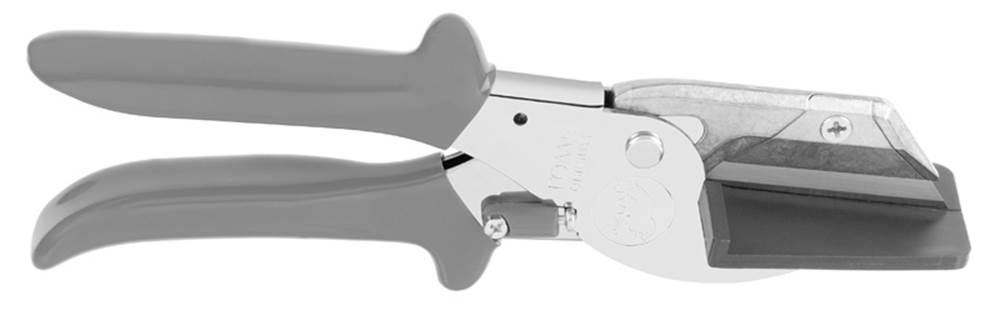
Figure 7-43. Ribbon cable cutter
Secondly, there cannot be any stray wire strands at the cut end of the cable, because they can cause all kinds of problems later on. Finally, the cut end of the ribbon cable should not protrude beyond the body of the connector, but should instead end up flush with the body and the pressure plate.
You assemble the IDC by pressing the parts together, and there is, of course, a tool for that as well. Figure 7-44 shows how an IDC compresses a ribbon cable to force the individual conductors into the contact blades.
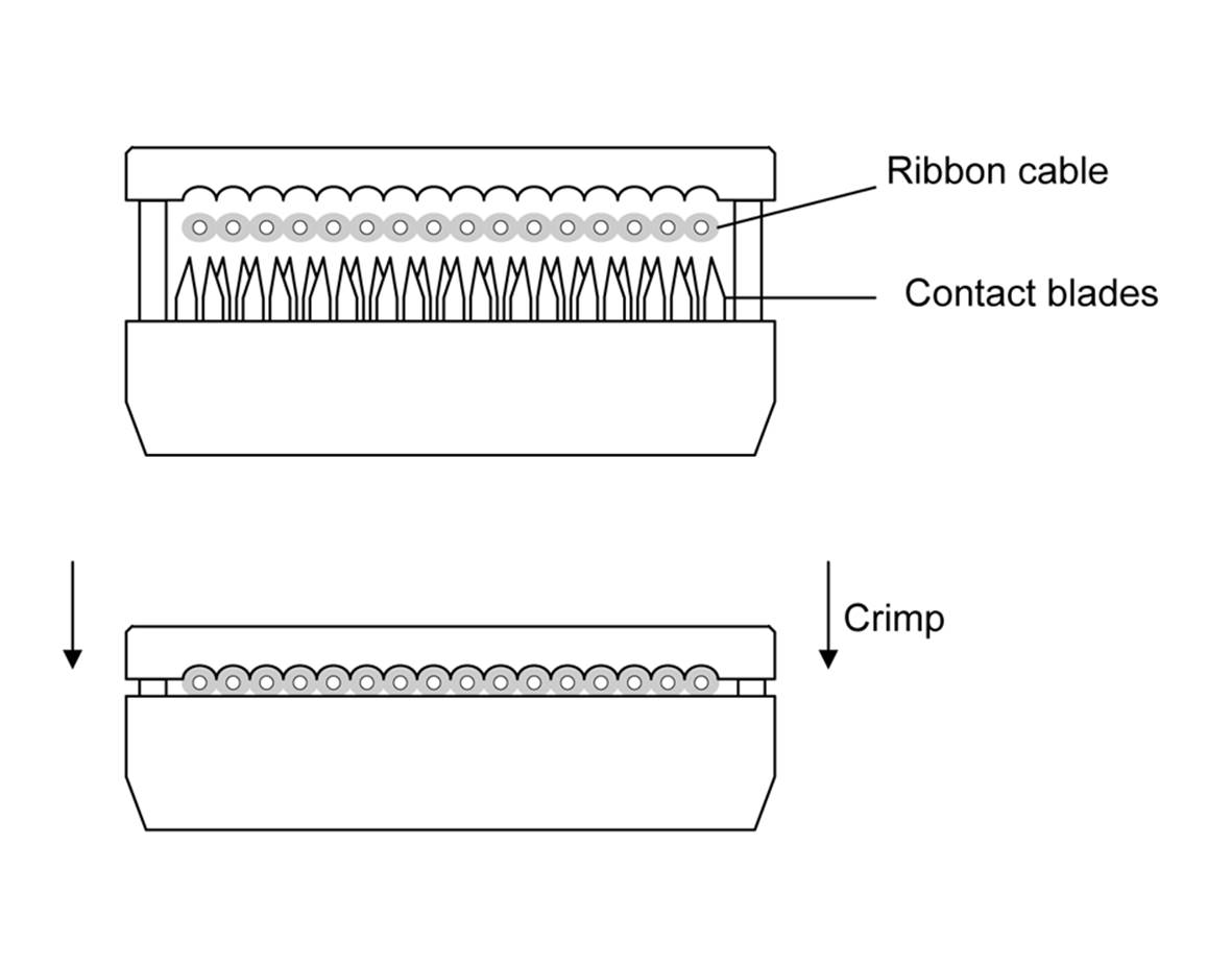
Figure 7-44. Before and after diagrams of IDC assembly
If you’re making only a small number of ribbon cable assemblies on a sporadic basis, a small bench vise will work, as long as you’re careful to keep things lined up while applying pressure. To avoid marring the connector body or damaging the socket holes, use a vise with soft jaw strips or place some thin strips of wood between the connector components and the metal surfaces of the vise jaws.
Ethernet Connectors
Unlike USB connectors, you can easily make your own Ethernet cables. Figure 7-45 shows an example of the type of tool used to do this. The crimping tools come in a diverse range of styles, from ultra-cheap (and not really worth buying) to robust, industrial-grade things made from machined steel. Avoid plastic crimping tools; they won’t last long and may actually cause more problems by making substandard connectors.
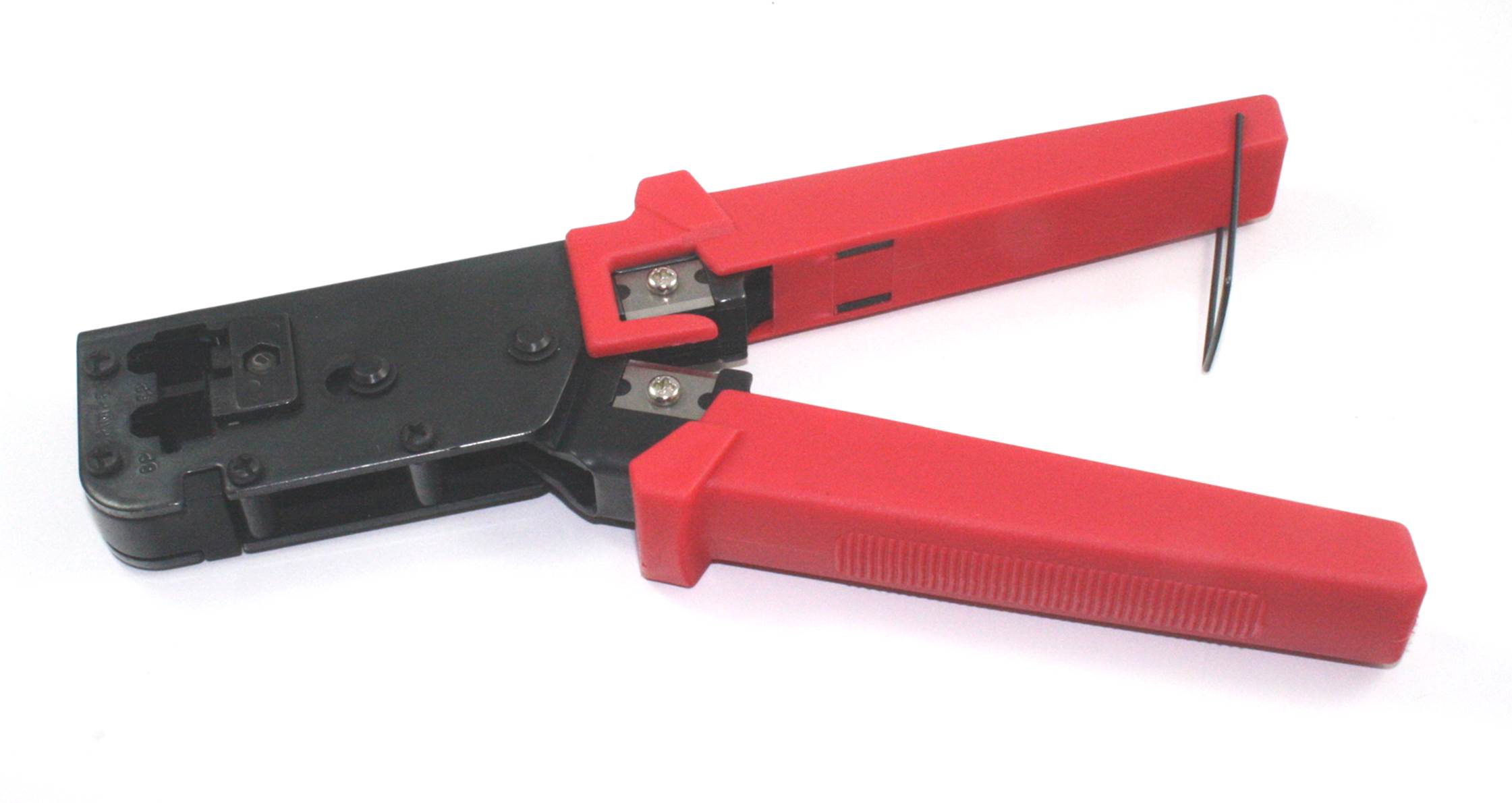
Figure 7-45. RJ45 connector crimp tool
Note that there are two basic cable types used for Ethernet: stranded wire and solid wire. Each uses a slightly different type of connector to accommodate the wire used in the cable. Typically, a cable with solid-core wire would be used in an application where the cable won’t see much flexure, such as wiring in a wall or a cable tray. Ethernet cables that will be moved, such as patch cables, are typically made with stranded-type wires for flexibility. The connectors used for each type are different internally, so be sure to use the correct connector shell for the wire type. Most crimp tools and cable kits come with an instruction sheet or pamphlet, and it’s a good idea to read it before using the tool.
An RJ45 connector works by forcing a thin metal blade or a slotted blade like those used in an IDC through each of the wires in a standard CAT5 or CAT6 Ethernet cable. This means that after the correct amount of outer insulation is removed from the cable, the internal wires must be separated (they are bundled as sets of twisted pairs) and then pushed into the connector in the correct order. This part usually takes a bit of practice to get it right each time.
Ethernet cable kits are readily available from a number of online sources, and even from some unlikely sources, such as large department and home improvement stores. Figure 7-46 shows an example of a kit that contains a cable cutter, wire stripper, and a crimping tool that will handle both RJ45 and RJ11 (telephone) connectors. It also contains a selection of RJ45 connector shells for both stranded- and solid-wire cables, as well as some RJ11 telephone-type connector shells. All that’s needed is a spool of Ethernet cable (not shown).
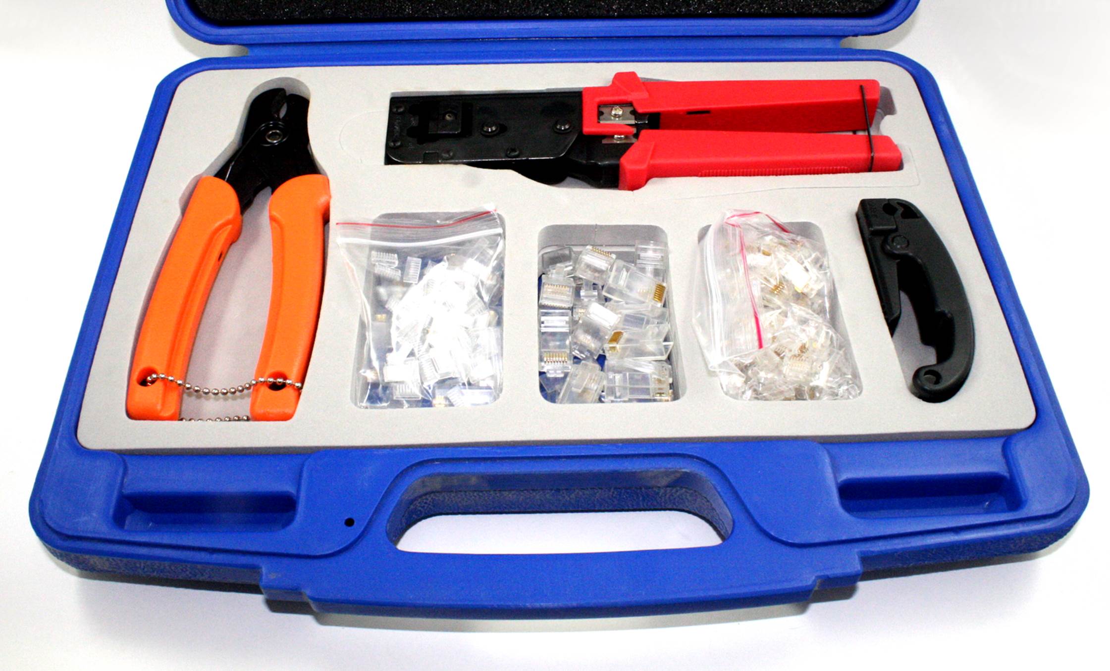
Figure 7-46. Ethernet and telephone RJ45/RJ11 connector kit
The proliferation of Ethernet has made it a common feature in many new homes. Many kits have RJ45 connectors for both solid- and stranded-wire cables, a cable insulation stripper, a ratcheting tool to crimp the connectors to the cable wires, and instructions. The cable can be purchased in spool lengths of anywhere from 25 to 1,000 feet.
Summary
This chapter has covered some of the more common connectors and wire types and shown you how to create complete connector and wire assemblies. With regard to connectors, an important point to remember is that any given type of connector might be available in a form that you can connect by soldering the wires, crimping the wires into individual contacts, mounting the connector on a PCB, or using an IDC method to deal with things like ribbon cables.
Selecting the right tool for the job is another important detail covered in this chapter. Connectors can be unforgiving, and the correct tool helps make the process less frustrating and produces better connectors. You might end up with a selection of different types of cutting and crimping tools, but if you use them more than just a few times, it’s not a bad investment.
We didn’t cover things like “F” connectors, BNC connectors, SMA and SMB miniature connectors, and DC power connectors. These are all relatively straightforward and easy to figure out, and there are a lot of sources of information available online. We also didn’t go over circular connectors, which are common in aerospace and industrial applications. This is where purchasing and disassembling some old surplus electronic equipment can be a valuable educational experience and, as usual, there are plenty of sources of information available, including NASA, the US military (in the form of military specification, or MIL SPEC, documents), and the connector manufacturers themselves.
All materials on the site are licensed Creative Commons Attribution-Sharealike 3.0 Unported CC BY-SA 3.0 & GNU Free Documentation License (GFDL)
If you are the copyright holder of any material contained on our site and intend to remove it, please contact our site administrator for approval.
© 2016-2026 All site design rights belong to S.Y.A.