Practical Electronics: Components and Techniques (2015)
Chapter 8. Passive Components
Passive components are the framework on which circuits are built. One way to think of a passive component is as something that only responds to voltage or current; it doesn’t exhibit any active control behavior. Stated more formally, a passive component either dissipates energy (resistors) or stores and releases energy (capacitors and inductors), but does not actively contribute energy.
Unlike transistors and integrated circuits, passive components don’t require a power supply, just whatever happens to be going through the circuit of which they are a part. In other words, a resistor simply resists, and a capacitor or inductor just responds to changes in voltage and frequency to store and release electrons in a consistently predictable way. There is no way, short of physical manipulation, to alter the intrinsic behavior of a passive device (as you’ll see, there are ways to physically manipulate a passive device and alter the behavior in a controlled way).
Something like a transistor, on the other hand, can be used with a control input to modify its response to voltage and current (i.e., it has gain), and active devices can exhibit nonlinear behaviors. An active device can also supply energy to a circuit via an external power source. For these reasons, transistors, and other semiconductor devices, are classified as active components (the subject of Chapter 9).
For an example of how important passive components are, a typical transistor circuit (perhaps a small headphone amplifier or an old-style portable radio) is composed primarily of passive components, with a few transistors scattered around. The passive components set voltage and current levels, couple signals from one part of the circuit to another, and filter out unwanted signals and AC currents. The transistors are the active gain elements that boost signal levels, produce regulated DC supply voltages and current, and serve as oscillators (in a radio circuit).
But passive devices can be more than just the “glue” of a circuit. It is possible to build functional and sophisticated electrical devices using only passive components by exploiting their passive behaviors. In fact, at one time, long ago, this was a popular approach, mainly because early active components like vacuum tubes tended to run hot, required high voltages, and weren’t very reliable. Go back far enough and vacuum tubes didn’t even exist, yet people were building fairly sophisticated electrical gadgets. For example, thumb through a book on Nikola Tesla and see how many vacuum tubes you can spot in photos of his labs. The answer is none, yet he was able to build a remotely controlled boat and created one of the first working radio-type devices. He did all of it using nothing more than resistors, capacitors, coils, and mechanical generators running at various speeds. All this in the late 1800s.
This chapter describes the physical characteristics of commonly encountered passive components such as resistors, capacitors, and inductors, including both through-hole and surface-mounted types. It also describes how to read component markings and how to understand component ratings for voltage, power, temperature, and tolerance.
Tolerance
Almost all passive components have values specified with a given tolerance, which is stated in terms of percentage. What this means is that a part with a 20% tolerance (for example) will have an actual value that is anywhere from –20% to +20% of the value stated for that part. So a resistor with a tolerance of 5% and a value of 10,000 (10K) ohms can be anywhere from 9,500 to 10,500 ohms and still be within tolerance. The same applies to capacitors and inductors.
It is important to bear in mind that precision is expensive. A part with a tolerance of 1% will cost more than a 5% part, and one with a tolerance of 0.1% can be very pricey. It is also important to remember the old axiom of electronics: if a circuit requires precision parts to work, it might not have been designed correctly.
There are only a few special cases where high precision is necessary. For the most part, electronic circuits are rather forgiving. This is particularly true when there is a knob for a user to turn, or some other means of adjusting the circuit during operation (as with an automatic gain control, for example).
Using a precision resistor in combination with a potentiometer is a classic example of a design that wasn’t thought all the way through, but precision resistors used to produce a bias or offset voltage might make sense in some types of high-precision measurement circuits. In general, precision parts should not be used unless there is a real and compelling need to do so.
Voltage, Power, and Temperature
In addition to whatever value a component might have (within its tolerance), passive components also have ratings for working and peak voltages, power dissipation, and usable temperature range. So long as a component is used within these limits, it will exhibit a value (ohms, microfarads, or millhenries) within its tolerance range.
Voltage is a fairly obvious limitation. A small part might not be able to tolerate an extremely high voltage, whereas a larger part, made from special materials, might be able to withstand thousands of volts.
The working voltage of a resistor is determined by how the material that is used to fabricate the part will withstand a high potential difference across it. If the working voltage is exceeded, the carbon or metal film material in the part can start to break down, resulting in failure (it either goes open, or its value will change unpredictably). Another failure mode in an over-voltage condition is arcing. In other words, at some point, the potential difference might be great enough to cause the current to arc across (or through) the resistive material to the opposite terminal.
For a typical carbon film resistor, the maximum working voltage will vary between 100 and 350V DC, depending on the manufacturer. In general, resistors rated for high-voltage applications tend to be longer than typical 1/4- or 1/2-watt parts, but length isn’t always a definite indication of high-voltage capability.
Capacitors have definite voltage limitations, since at some point, the dielectric material will cease to be an insulator and become a conductor. Most small ceramic capacitors are capable of withstanding 50V DC. Other types can work with voltages up to 500V or more, and still others that use oil as the dielectric can handle thousands of volts. Always check the voltage rating on an electrolytic or tantalum capacitor. If the maximum voltage is exceeded, the part can fail in a rather spectacular fashion (often involving a small ball of fire and flying sparks).
For most circuits operating in the 3V to 9V range, the voltage ratings of the components aren’t really a major concern. It does become a concern when you’re dealing with the input side of a switching power supply, a high-voltage charging circuit for a flash tube, or a vacuum tube circuit (yes, people still build and use these).
The power rating of a component is the maximum amount of power, in the form of heat, that the part can safely dissipate before it becomes something resembling charcoal. Recall from Chapter 1 that DC power is computed as the product of the voltage potential and the amount of current (P = EI). Axial lead through-hole resistors, for example, are rated at values of 1/8, 1/4, 1/2, 1, and 2 watts, with other ratings possible. Surface-mount parts can be found with power ratings ranging from 0.03 to 1 watt, depending on the size of part. For DC circuits, power ratings apply primarily to resistors. For more information about capacitors and inductors, see Appendix A or consult one of the texts listed in Appendix C.
Temperature can have a significant effect on the behavior of a passive component. Almost all resistors will exhibit some degree of temperature sensitivity, and the performance of a capacitor can be severely degraded if it is operated outside of its rated temperature range. Fortunately, many circuits don’t experience temperature extremes, although heat can be a problem with things like solar panel tracking controllers or an engine controller for a vehicle. High-performance computers can also have thermal issues. Devices such as outdoor weather sensors might see some extreme high or low temperatures, depending on the local climate, but there are ways to deal with this using internal heating elements, insulated enclosures, or active cooling systems.
As a general rule, if you have a circuit that will utilize high voltages, operate at high power levels, or operate in an environment subject to temperature extremes, it would be a good idea to get the component specifications from the manufacturer. These so-called datasheets have all the parametric values for a given part (or family of parts). Chapter 9 contains a walk-through on how to read a datasheet. Appendix D lists component distributors.
On the other hand, if you are building a small robot, hacking a household appliance so it can join other appliances in a local network, or just modifying something that uses batteries or a wall power supply, you probably don’t need to worry about temperature or voltage ratings too much. You still need to be aware of power ratings, since, as mentioned in Chapter 1, a AA battery can deliver an impressive amount of current.
Packages
Through-hole (non-surface-mount) passive components come in one of two basic package types: axial and radial. Figure 8-1 shows the difference between the two.
Other packages are used for special-purpose components, such as resistors in TO-220 style packages originally designed for transistors. In general, however, these are the two styles most often encountered with low-voltage, low-current electronic circuits.
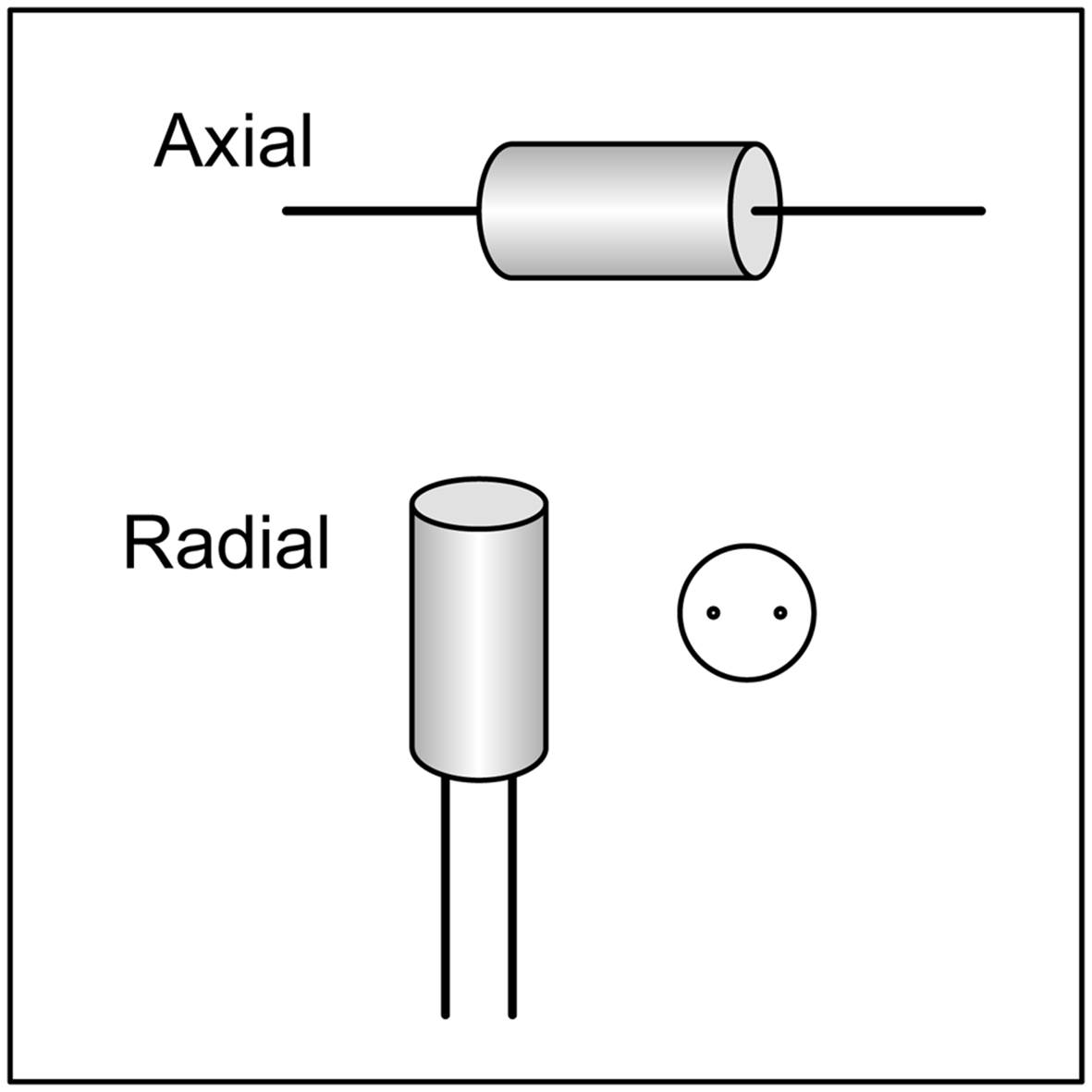
Figure 8-1. Axial and radial package types
Surface-mount packages are a subject unto themselves, and they are covered later in this chapter. Capacitors, inductors, and resistors are all available as surface-mount devices, and the package nomenclature is generally the same for the various component types.
Resistors
Resistors are the most ubiquitous type of electronic component and also one of the oldest. They come in both fixed-value and mechanically variable types with power-handling capability ranging from a less than 1/10w to hundreds of watts or more. Cadmium sulfide photocells are photo-sensitive resistors that have found applications ranging from electronic music synthesizers and guitar effects pedals (e.g., Jimi Hendrix’s famous “Cry Baby” wah-wah pedal sound) to daylight detectors in street lamps and the light-beam intrusion detectors used in some burglar alarm systems.
Other types of resistors are temperature sensitive and are often found in thermostat control circuits, and one type is sensitive to humidity. Others are designed to serve as strain gauges, changing their resistance in response to mechanical deformation.
Physical Forms
Resistors come in a variety of sizes and package types. Axial lead components, with wire leads protruding from either end, are common. High-power parts might have solder lugs or even screw terminals on both ends. Surface-mount parts have no leads at all, but instead are soldered directly to a printed circuit board. Figure 8-2 shows a selection of the various physical shapes available for fixed-value resistors.
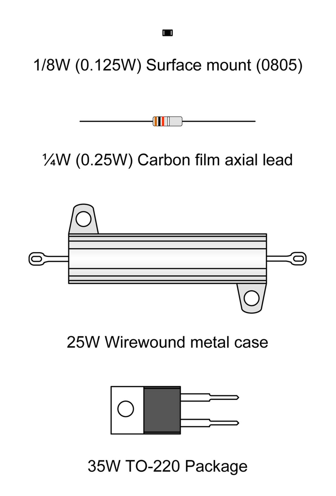
Figure 8-2. Examples of the various package styles available for resistors
You should note that much of what can be said about axial lead fixed-value resistors can also apply to surface-mount parts. Figure 8-3 shows a scale comparison of axial lead and surface-mount resistors. Rulers are provided to give a sense of just how small some of these parts really are. Also, notice how much smaller the surface-mount parts are compared to the smallest axial lead component shown, the 1/8w (.125W) resistor. This size scale difference applies to most surface-mount components relative to their through-hole counterparts.
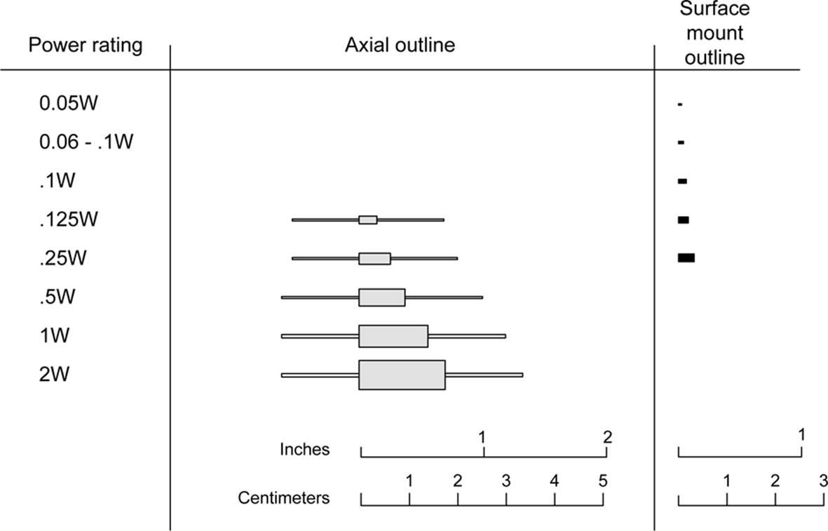
Figure 8-3. A scaled comparison of axial lead and surface-mount resistor sizes
In the technical data from component manufacturers, and in the catalog listings of many distributors, you will often find component wattages given in decimal form, while in everyday usage, we refer to 1/10 watt, 1/8 watt, 1/4 watt, and so on. The decimal values are necessary for performing calculations, and they can be easily displayed on a web page, whereas the fractional forms are more intuitive to many people and seem to appear more frequently when we are talking about the wattage of a part. In this chapter, for example, when discussing a 0.125W component, it will usually be written as 1/8W, not 0.125W. In tables and figures, it might appear as 0.125W or 1/8W, depending on the context. The reality is that you need to be able to switch from one format to the other as necessary, just as when dealing with dimensions (as covered in Chapter 4).
Another package is the resistor array, a set of resistors all of the same value arranged either as individual components in a common package or connected to a common lead. Figure 8-4 shows a single in-line package (SIP) with multiple resistor elements. Each lead is one end of a resistor, and the other ends are all connected to a common pin.
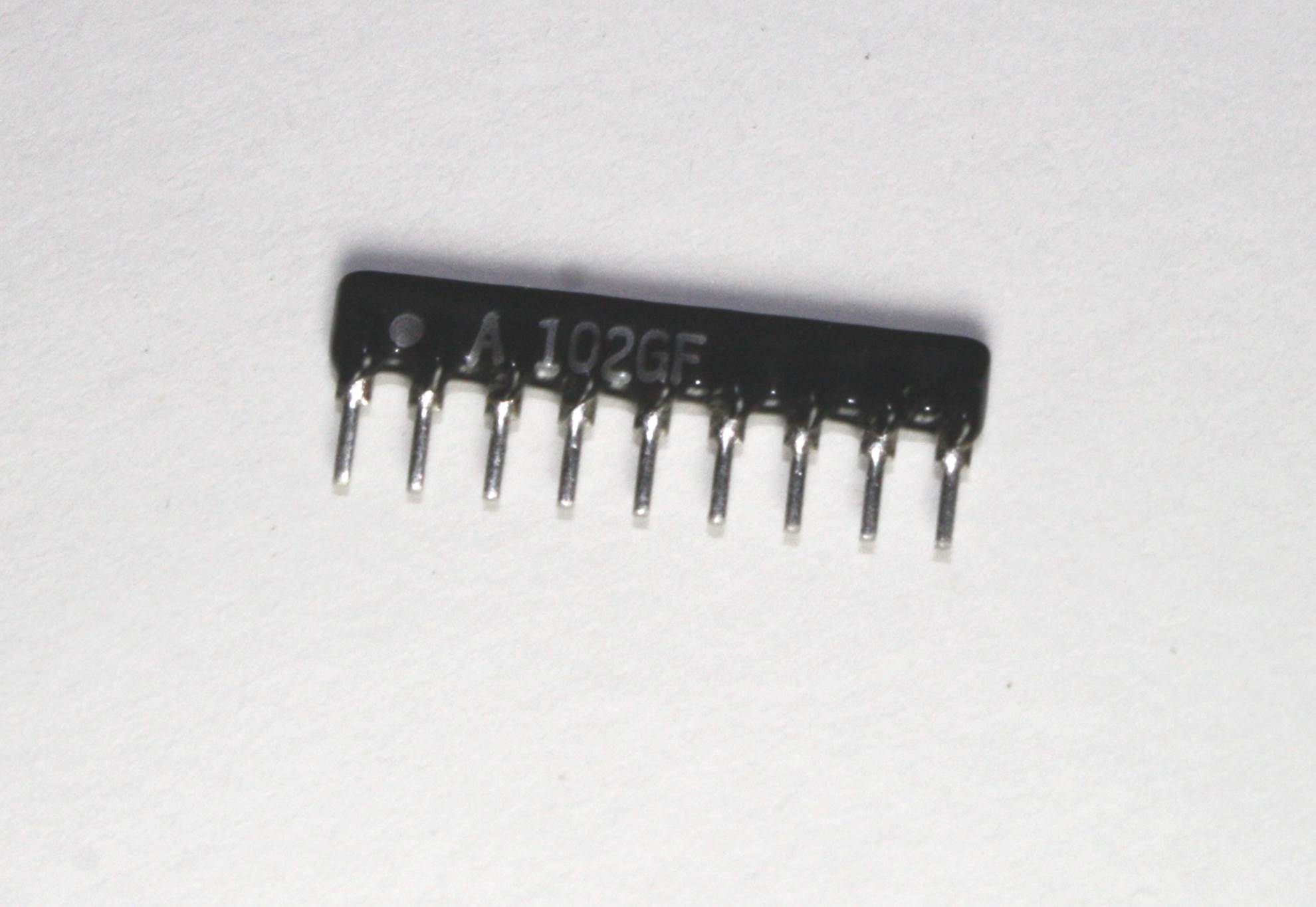
Figure 8-4. Single in-line package resistor array
Resistor arrays are also available in dual in-line packages (DIP) identical to those used for integrated circuits, and surface-mount packages as well. The array shown in Figure 8-4 is a set of eight 1 k ohm resistors with a common lead (hence the nine pins on the package). These parts are used for pull-up resistors on a parallel digital bus, current limiters for seven-segment LED displays, and as a way to conserve PCB real estate.
Fixed Resistors
Early resistors from around the early part of the 20th century that are still recognizable as such today were typically large clunky things consisting either of a ceramic tube with a resistive wire wound around it, or a solid rod of resistive material (carbon-based). Metal end caps and leads were used to make the connections, and the whole thing might be covered with some kind of ceramic or shellac coating. The color code for the value was painted on the body of the device, sometimes by hand. These devices were usually about the diameter of a common #2 pencil and around an inch or so in length. Some types had a tendency to emit copious amounts of smoke, or even burst into flames, if they were severely abused.
Modern fixed-value resistors come in a variety of forms, with the most common being the carbon film and metal film types. Other types include carbon composition and wire-wound designs. The selection of the type of resistor used in a design will depend on factors, such as power-handling requirements, precision needed, and physical size constraints. In this section, we’ll look at some of the common types you are likely to encounter. A look through a national distributor’s catalog or website will reveal more exotic types of resistors, but for the most part, you shouldn’t need to worry about them.
Carbon Composition
A carbon-composition resistor contains a solid core of resistive material with leads attached to either end. Figure 8-5 shows a couple of carbon-composition resistors.
The carbon-composition resistor was once common, mostly prior to the 1980s. They can still be found in older electronic devices, and if you plan to use old “junk” gadgets and appliances for parts, you will most likely see quite a few of them. They have since been replaced by carbon and metal film types, and while you can still purchase carbon-composition resistors, they are expensive compared to the film types. For a definition of the color codes, see “Resistor Markings”.
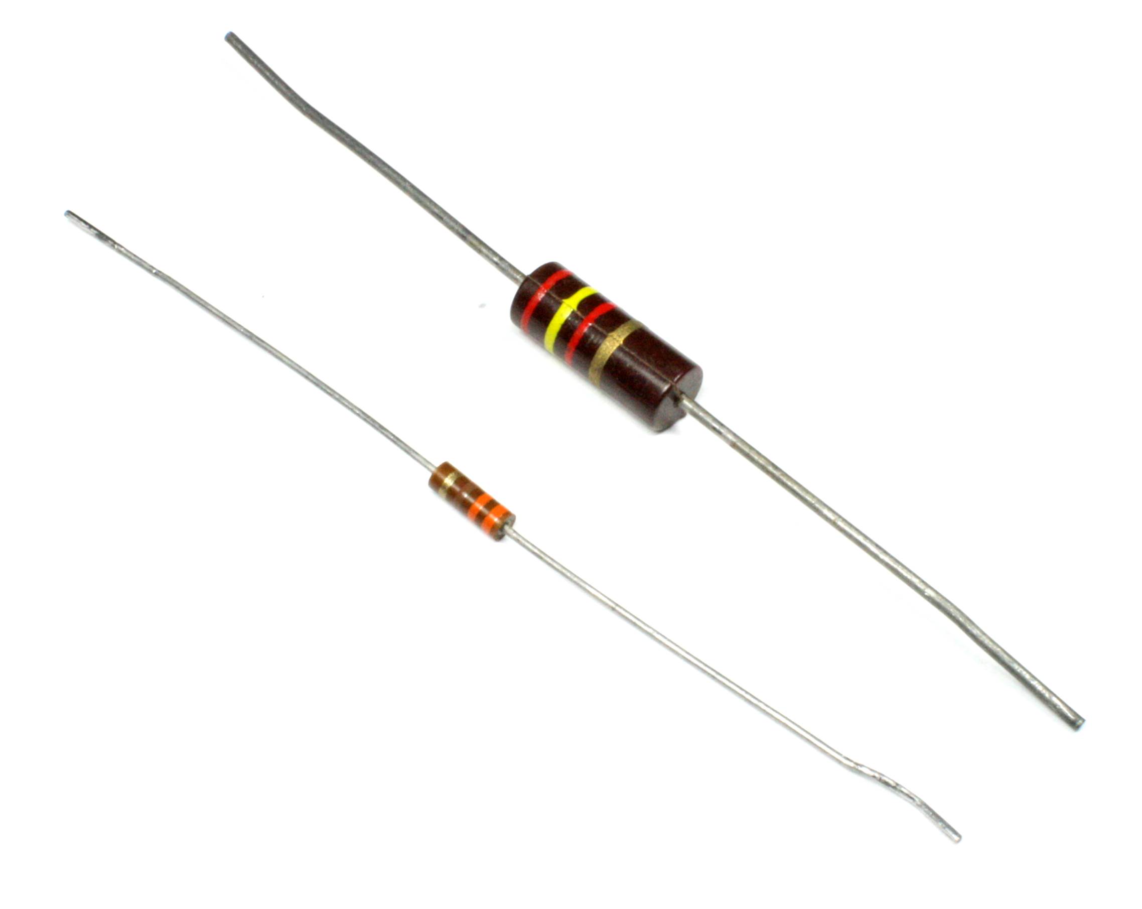
Figure 8-5. 1/4 and 1W carbon-composition resistors
Carbon Film
As the name implies, a carbon-film resistor consists of a thin layer of a carbon-based material deposited on an insulating substrate such as ceramic. The resistance is determined by the physical dimensions and thickness of the deposited film. Figure 8-6 shows a typical 1/4W carbon-film resistor.
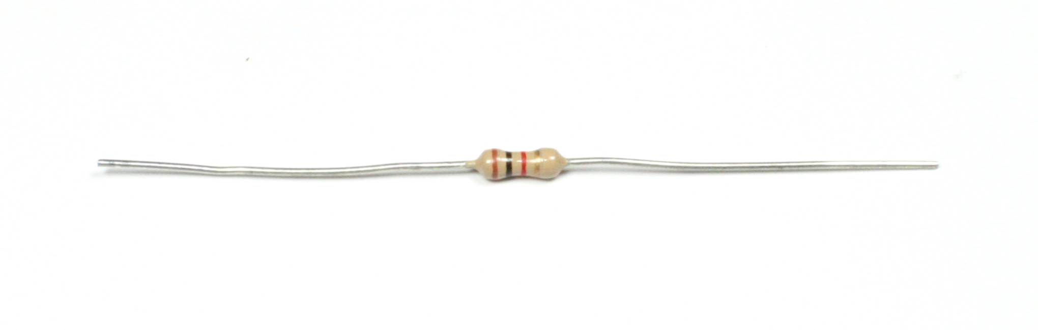
Figure 8-6. A typical 1/4W carbon-film resistor
Power ratings of 1/8 and 1/4 watt are commonly used, although carbon-film resistors are available with up to 5 watts of power dissipation capacity. Prices for 1/8-watt parts are typically around 1.6 cents each in quantities of 1,000, or about 30 cents each when purchased in small quantities at an electronics retailer. For a definition of the color codes, see “Resistor Markings”.
Metal Film
Metal-film resistors are typically used when the tolerance needs to be better than what can be obtained from other types. The film, usually an alloy of nickel, is first deposited and then any excess is physically removed to adjust the part to the desired value. Tolerances from 2% down to 0.5% are available, with the higher tolerance parts costing more, as you might expect.
Physically, a metal-film resistor might look a lot like a carbon-film type, except that it will have an additional color band to indicate a third significant digit for its value. Figure 8-7 shows a typical precision axial lead, metal-film resistor.
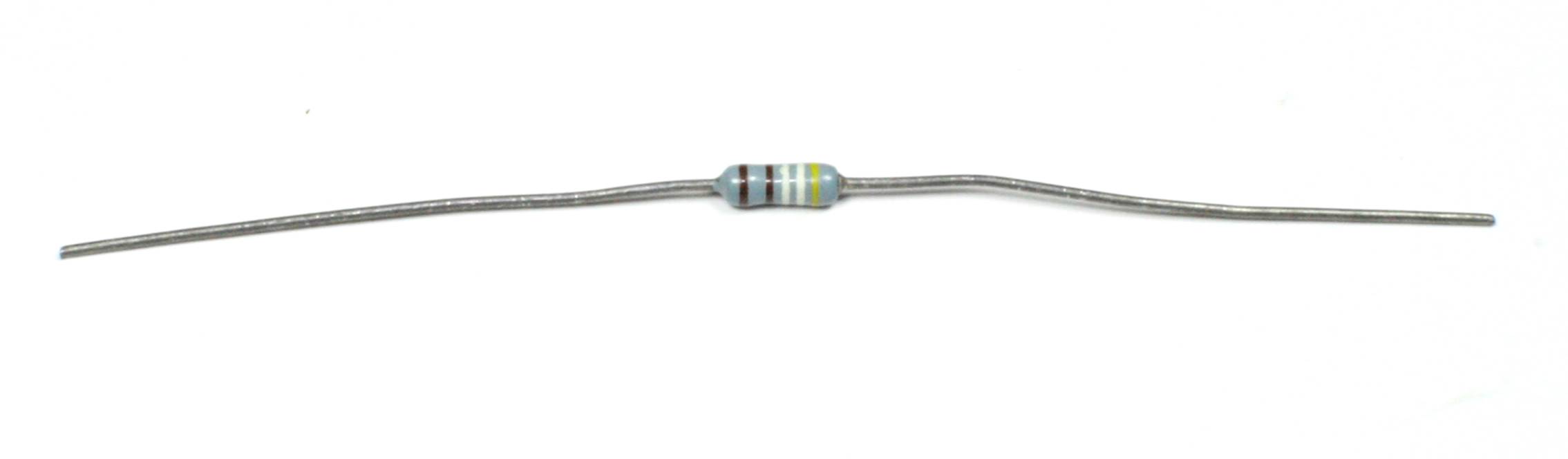
Figure 8-7. A precision metal-film resistor
Precision resistors are sometimes used in measurement circuits where you need to establish a definite voltage or current level for some type of sensor. For the most part, however, precision parts are not necessary for most circuits, and there’s no compelling reason to pay extra for the unneeded precision. For a definition of the color codes, see “Resistor Markings”.
Wire-Wound
Modern wire-wound resistors are similar to their ancient ancestors and use the same concept of a resistive wire on a ceramic core form. These types of resistors are most commonly used for high-power applications wherein the part will need to dissipate many watts of power without self-destructing. Figure 8-8 shows a type called a sandbox resistor, which has a ceramic outer shell containing the wire-wound resistive element in a ceramic potting matrix. These types come in a variety of power ratings. This one happens to be a .47-ohm, 5-watt part. It is used as a current limiter in the output stage of a high-power amplifier.
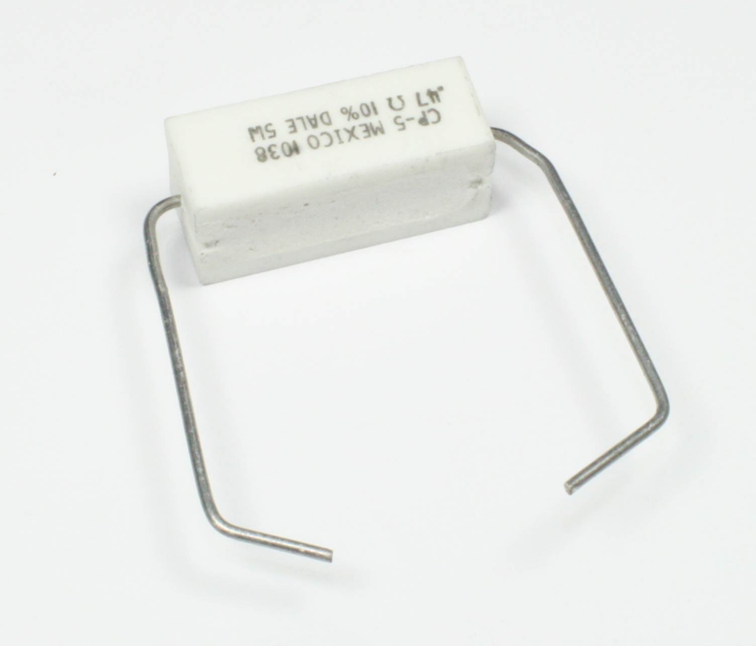
Figure 8-8. A “sandbox” wire-wound resistor
Another common style utilizes a metal shell, typically aluminum, with the wire-wound element encapsulated inside. Figure 8-9 shows a metal case wire-wound resistor. The advantage of the metal shell is that it can be attached to a larger surface that can act as a heatsink.
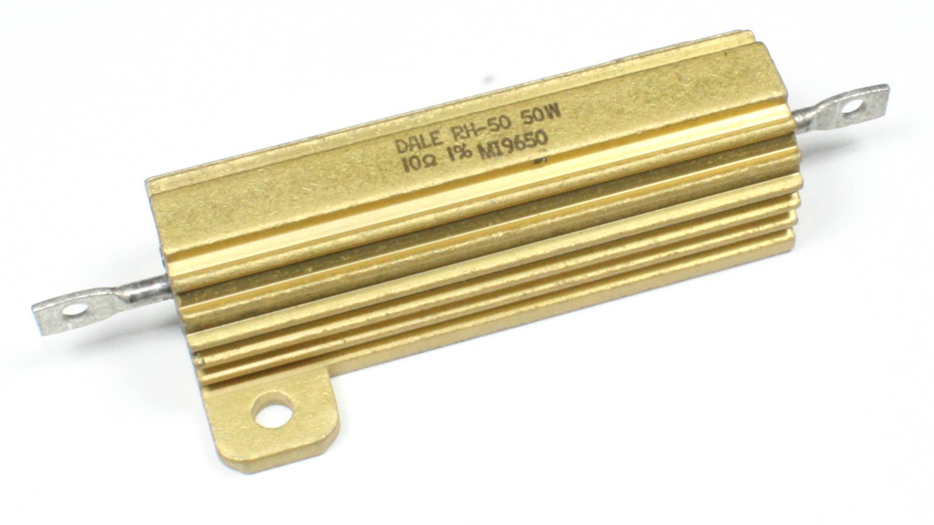
Figure 8-9. A metal case, wire-wound resistor
Applications for high-power wire-wound resistors include supplying heat in test chambers, dumping excess energy in a diesel-electric locomotive (the vents on the end of a locomotive engine aren’t for a radiator; they are for the fans that cool banks of resistors), and serving as so-calleddummy loads used to test audio amplifiers and radio transmitters.
Wire-wound resistors tend to be inductive, due to their construction. They can also exhibit capacitance between the windings. Manufacturers try to minimize these effects, but they can never be completely eliminated. For this reason, you will almost never see a wire-wound resistor in a circuit that deals with high-frequency signals, unless of course the effect of the resistor was taken into account when the circuit was designed. They are used to limit current through output devices like transistors and FETs (field-effect transistors), in linear power supplies, and in some battery-charger control circuits.
Precision wire-wound resistors in the low-power range (approximately 1W or less) use the same color code scheme as carbon composition, carbon film, and metal film resistors. For a definition of the color codes, see “Resistor Markings”. Larger parts (greater than 1W) typically have the value printed on the body of the part, as shown in Figure 8-8.
High-Power Packages
High-power resistors are available in packages other than the axial-lead forms shown in Figures 8-8 and 8-9. The type shown in Figure 8-2 in a TO-220 package was originally designed to house high-power transistors. Other types include devices up to several feet in length and many inches in diameter, with heavy mounting tabs at each end for the electrical connections.
High-power resistors are typically used to safely dissipate unwanted energy or provide a source of heat. One application for the TO-220 style package is when there is a need to heat a flat metal surface, such as in a thermal-vacuum test chamber. An array of TO-220 resistors can provide the necessary heat. Arrays of high-power resistors are also used to dissipate the energy produced by the electric motors in a diesel-electric locomotive during dynamic braking.
In more common settings, high-power resistors in nonstandard packages can be used to build things like load simulators for power supplies, dummy loads for audio amplifiers, a safe heat source for a small epoxy curing oven, or heaters to keep a small remote sensor from freezing when deployed in sub-zero temperatures.
Surface-Mounted Fixed Resistors
While axial lead resistors were once the norm for electronics, they are being replaced by surface-mount parts. This is both good and bad, depending on your perspective. It’s good because surface-mount technology (SMT) parts are smaller, cheaper, and more easily incorporated into an automated production system. It’s bad because SMT parts can be difficult to work with by hand. In fact, some parts are so small that it is almost impossible to work with them, even when using a microscope and specialized tools.
Surface-mount resistors are available in carbon composition, carbon-film, ceramic, and metal-film forms. They are available in other formulations as well, depending on the power rating and tolerance. Figure 8-3 shows some of the various package types in scale with axial lead components.
Figure 8-10 shows a surface-mount resistor, along with a 680 ohm, 1/10W part in a 0805 package. “Resistor Markings” describes the numbering system used with surface-mount resistors.
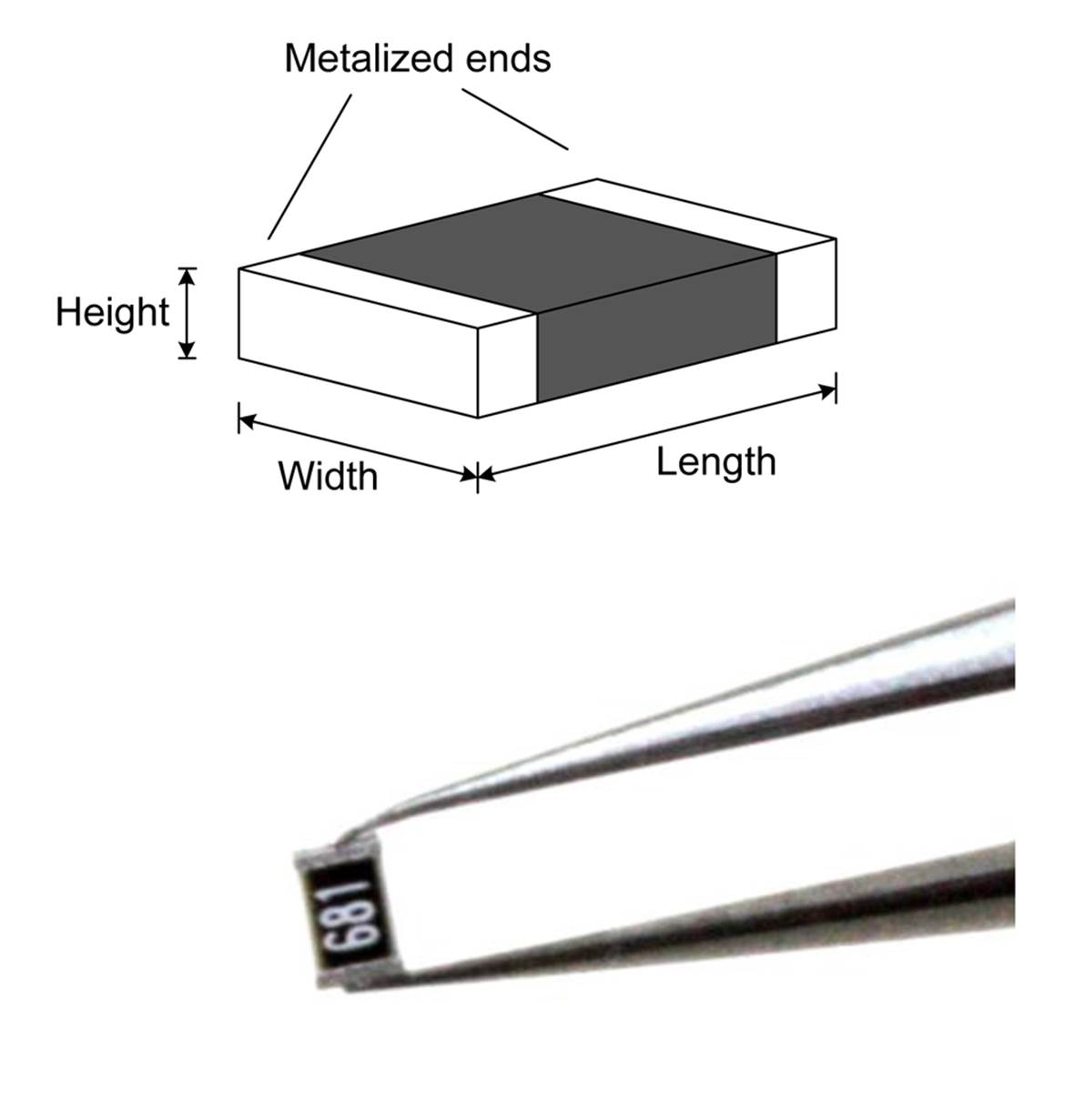
Figure 8-10. A 1/10W surface-mount resistor
Table 8-1 lists common package types for surface-mount resistors. Note that these are typical sizes; the actual sizes may vary slightly from one manufacturer to the next. Check the specifications before assuming anything about the dimensions of a particular part. Also note that the wattage may vary between parts of a particular size, so be sure to double-check the specifications before making any assumptions.
|
US |
Metric |
Length |
Width |
Watts |
|
0201 |
0603 |
0.024 (0.6 mm) |
0.012 (0.3 mm) |
0.05 |
|
0402 |
1005 |
0.039 (1.0 mm) |
0.020 (0.5 mm) |
0.03/0.063 |
|
0603 |
1608 |
0.063 (1.6 mm) |
0.031 (0.8 mm) |
0.063 |
|
0805 |
2012 |
0.079 (2.0 mm) |
0.049 (1.25 mm) |
0.1 |
|
1206 |
3216 |
0.126 (3.2 mm) |
0.063 (1.6 mm) |
0.125 |
|
1210 |
3225 |
0.126 (3.2 mm) |
0.098 (2.6 mm) |
0.25 |
|
2010 |
5025 |
0.197 (5.0 mm) |
0.098 (2.6 mm) |
0.25 |
|
2512 |
6332 |
0.25 (6.3 mm) |
0.13 (3.1 mm) |
0.5 |
|
Table 8-1. Nominal surface-mount resistor sizes |
||||
You might notice a pattern in the package types codes in Table 8-1. The numbering system is based on the length and width of the part, so, for example, a resistor with a length of 0.039 inches (1.0 millimeters) and a width of 0.02 inches (0.5 millimeters) is given the package code 0402 and the metric code 1005. The first two digits in each code refer to the length, and the last two refer to the width.
Chapter 4 includes an example of soldering a surface-mount resistor onto a PCB. This was done with the same 0805 part shown in Figure 8-10, along with some solder paste to make the process easier. A skilled technician with a bench microscope, good tweezers, and an SMT soldering station can work with parts down to about the 0402 (1005 metric) package size. Anything smaller than that becomes increasingly difficult or impossible to do by hand, and yes, there are much smaller parts available.
Variable Resistors
Variable resistors can be adjustable types with fixed or adjustable taps. Two-terminal variable resistors (typically wire-wound types) with a sliding contact arranged so that the device can be operated using a knob are called rheostats.
A three-terminal variable resistor designed so that a wiper slides across a resistive surface (usually a carbon-based material) is called a potentiometer (or just a pot). There is a terminal at either end of the resistive element and a third connected to the wiper. A three-terminal potentiometer is, in effect, a continuously variable voltage divider.
Rheostats
The rheostat was invented around 1845 by Charles Wheatstone, an English scientist and inventor who also developed the Wheatstone bridge, musical instruments, and a cipher method, among other things. The term rheostat combines the two Greek words rheos (meaning stream) and stat(meaning to regulate).
A rheostat is typically a two-terminal variable resistor, usually built around a coil of wire formed into a semicircle or wound along an insulating tube. A conductive material, such as a carbon-based ceramic, is also sometimes used as the resistive element. Rheostats that employ resistive wire are commonly used in situations where the device must dissipate significant amounts of power.
Figure 8-12 shows a generic version of a rheostat, like the high-wattage types that might be found in an old-style temperature control for a soldering iron or as a control in a lighting system. This one happens to have three terminals, but it’s still classified as a rheostat. To make it a true two-terminal device, the center terminal is connected to one of the two terminals to either side. Similar types can be found in the passive filter module of a high-end loudspeaker, and they were once common in the power supplies for model trains. This one happens to be an Ohmite RHS50R, which is a 50-ohm part rated at 25 watts.
Rheostats like the one shown in Figure 8-12 are tough and durable, and it’s not uncommon to find them still in perfect working order when disassembling some old piece of electrical equipment. Note, however, that rheostats do tend to get hot when handling large amounts of current, so make sure to take this into consideration.
Linear slider types, like the sliding rheostat shown in Figure 8-11, are sometimes used in laboratories and in some industrial applications. These are similar in most aspects to the original devices created by Wheatstone. All that has really changed over the past 165 years are the materials used to build the device.
Note that, for low-power applications, a potentiometer (discussed in the next section) can be, and often is, wired to behave as a rheostat by having the wiper terminal connected to one of the end terminals.
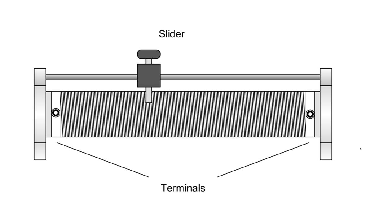
Figure 8-11. Diagram of an old-style sliding contact rheostat
Potentiometers
Potentiometers come in a range of sizes and power ratings. Some can handle several watts of power, while others are small and rated for only fractions of a watt. Some types are designed to mount in a hole using a nut and lock washer or mounting screws, while others can be soldered directly to a PCB.
One common type of potentiometer utilizes a semicircular strip of carbon-based resistive material with a metal wiper contact that slides across the surface as a shaft is turned. There are three terminals, as shown in Figure 8-13. One way to think of a potentiometer is as a continuously variable voltage divider (see Chapter 1 and Appendix A for information on voltage dividers), which is how these devices are typically used.
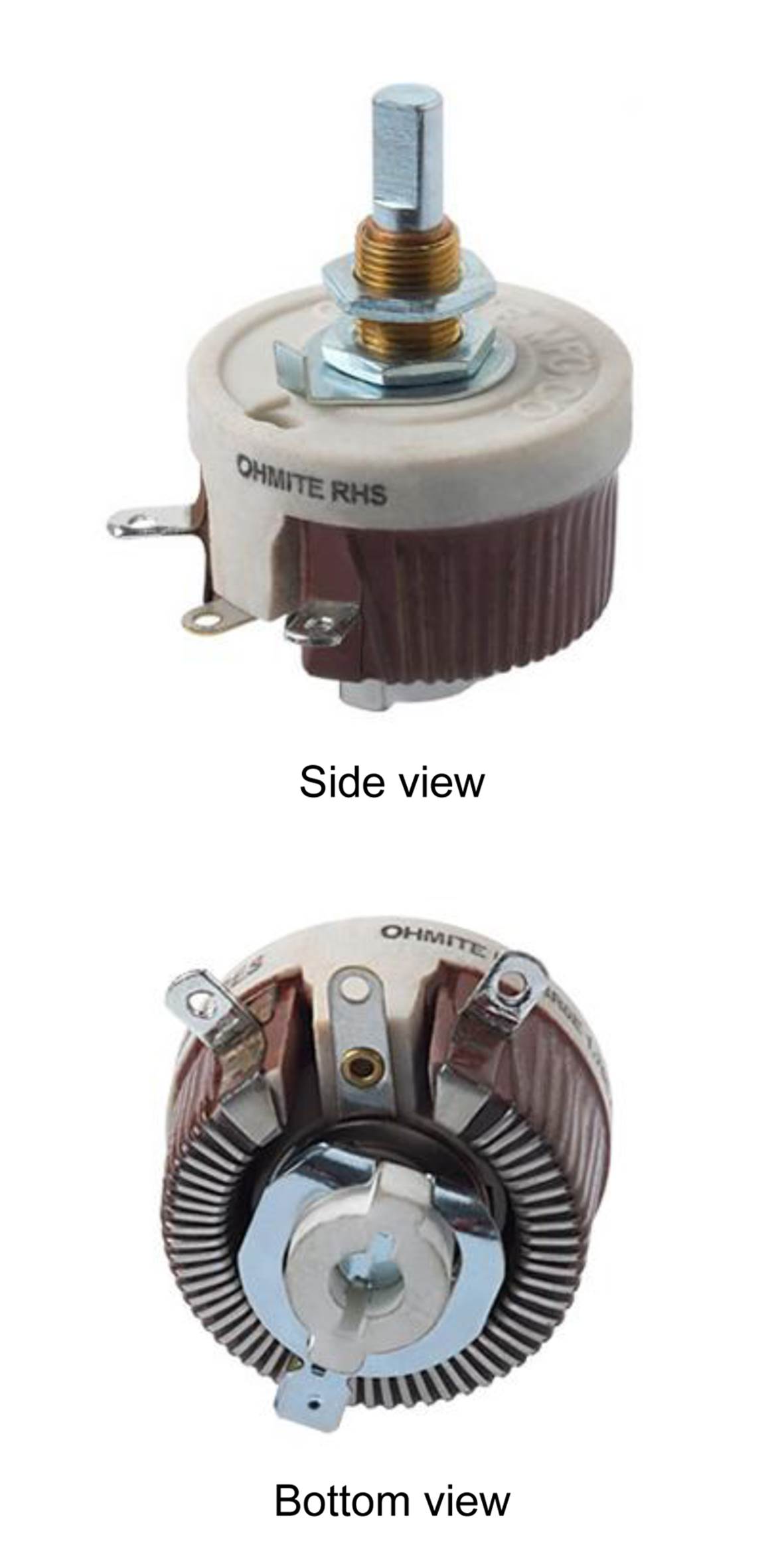
Figure 8-12. Example rheostat device
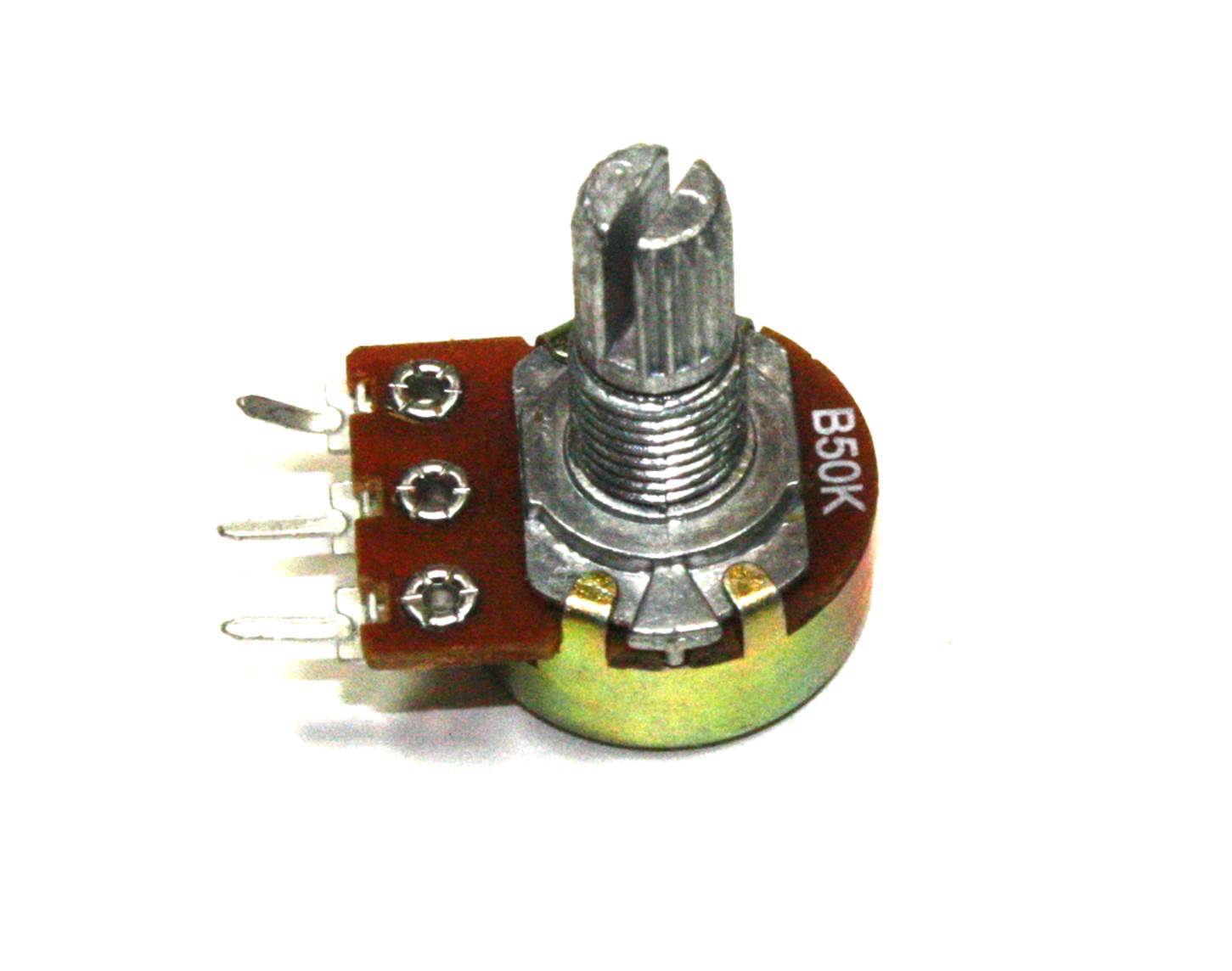
Figure 8-13. Single-turn potentiometer (PCB mount, threaded shaft)
Figure 8-14 shows a selection of trimmer potentiometers designed for PCB mounting. These potentiometers are designed to be adjusted with a small plastic tool similar to a screwdriver. These are often referred to as trimmer potentiometers because they are intended to be set once (or at least not very often) to adjust (or trim) a circuit and then left in the appropriate position.
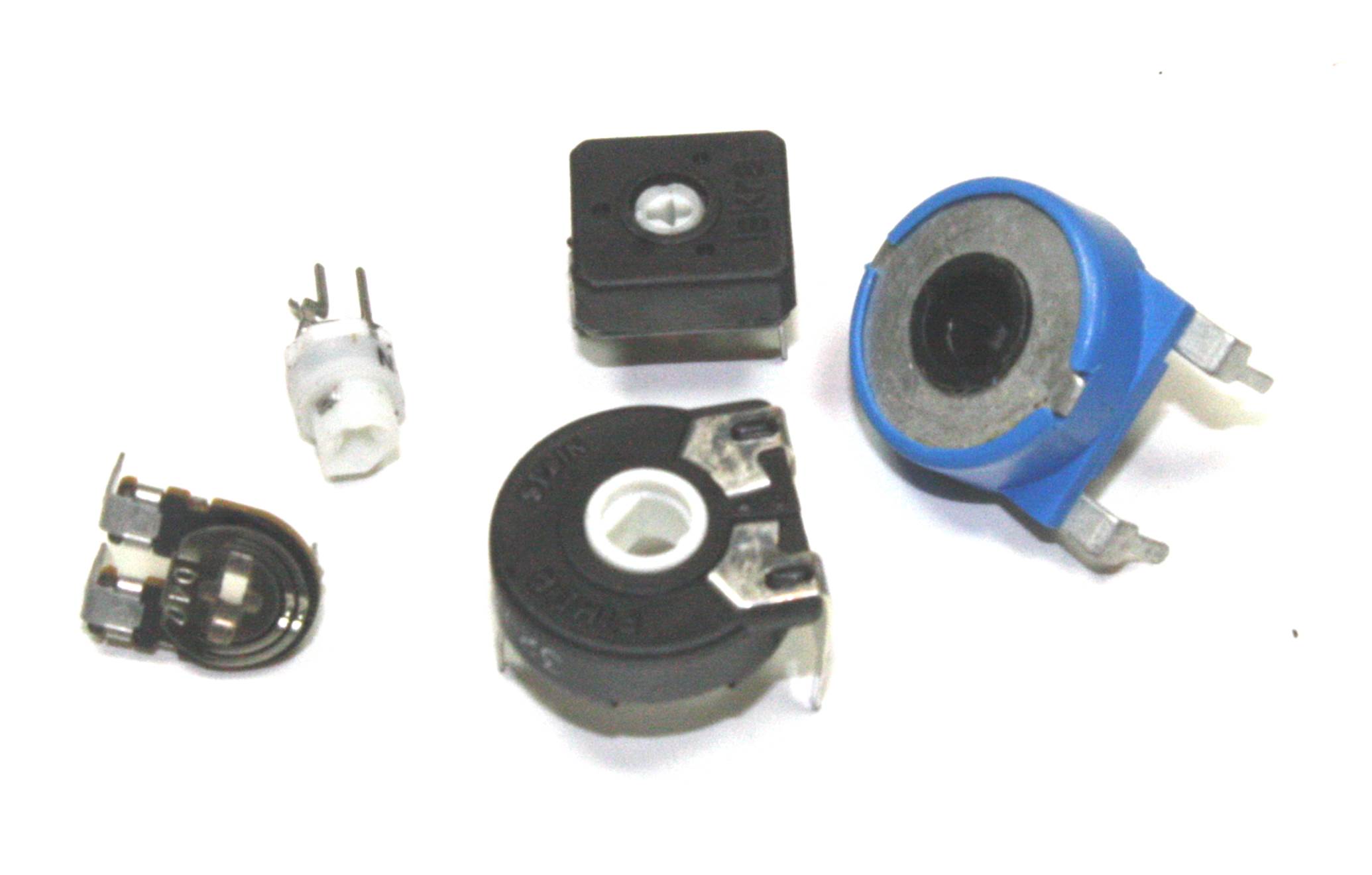
Figure 8-14. Various sizes of trimmer potentiometers
In addition to a circular rotary form, potentiometers also come in linear, or slider, styles. The primary physical difference between a linear potentiometer and a rotary type is the physical arrangement of the resistive element and how the contact wiper moves across it. These are commonly found in things like the audio mixers used in recording studios, public address systems, and stage lighting control systems.
Figure 8-15 shows an example of four slider linear potentiometers mounted on a PCB. Small rectangular knobs press onto the ends of the shafts, although this is more a cosmetic aspect than a functional requirement (in this case, I think the knobs have been long lost). The front panel has four slots cut to allow the shafts to protrude through when the PCB is mounted.
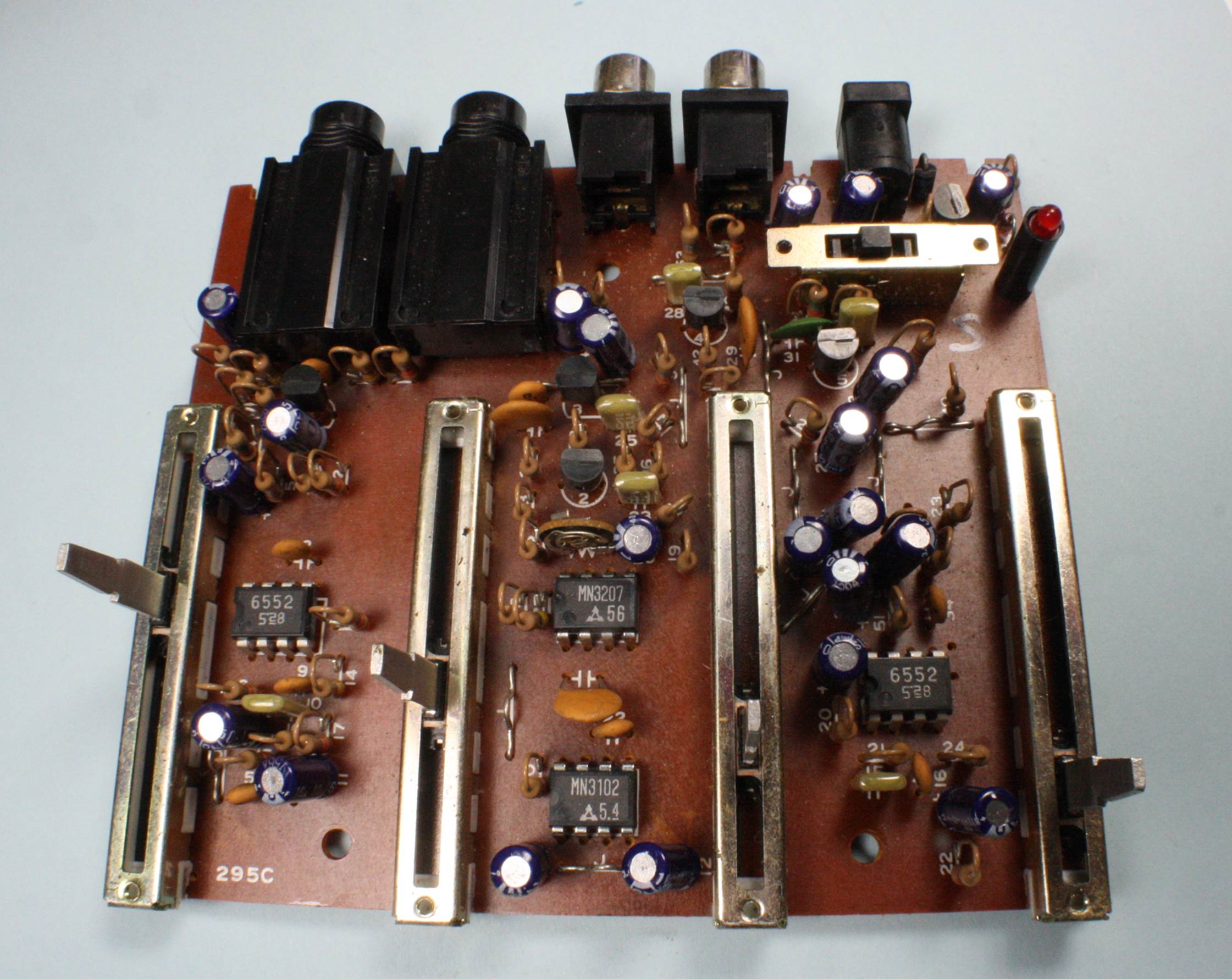
Figure 8-15. Linear slider potentiometers on a PCB
Linear potentiometers are also sometimes used as position sensors. Figure 8-16 shows a couple of examples of linear potentiometers configured as motion sensors. The top diagram is a tubular device with a shaft. The lower diagram is a variation on the type of slider potentiometer shown inFigure 8-15, except that this type mounts to a panel or bracket with small bolts.
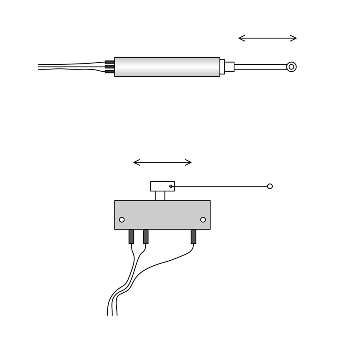
Figure 8-16. Linear potentiometers configured as position sensors
Outside of position-sensing applications, the primary advantage of a linear potentiometer over a rotary type is that it provides an easily comprehended visual indication of its setting. Physically mounting a linear potentiometer is more involved than just drilling a hole, since it needs a slot for the contact arm to move within, and some types are designed to be attached to a panel with small screws at each end of the body of the part. The types intended for use as motion sensors have mounting arrangements specifically intended for motion sensing applications.
Multi-Turn Potentiometers
A multi-turn potentiometer is designed for situations that reaquire a fine degree of control. They are usually precision devices. Like single-turn potentiometers, they are available in a range of styles and sizes, from large devices suitable for panel mounting to miniature parts designed for mounting on a PCB. Figure 8-17 shows a miniature type. These are available in several different package types and are typically referred to as trim potentiometers because they are primarily used to adjust some aspect of an active circuit. Almost all of the miniature types like this are adjusted with a screwdriver or something similar.
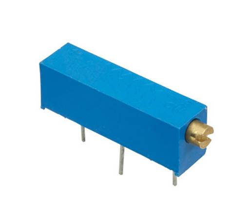
Figure 8-17. A miniature multi-turn “trim” potentiometer
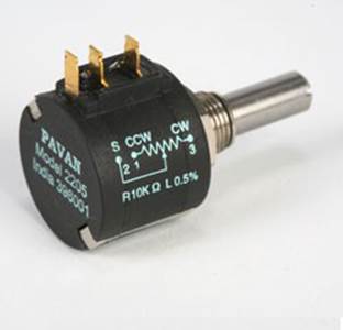
Figure 8-18. Panel-mounted, multi-turn potentiometer
Larger multi-turn potentiometers, like the one shown in Figure 8-18, come with a shaft that can be fitted with a special knob that counts the number of full turns and incorporates a graduated circular scale, as shown in Figure 8-19. This allows an operator to “dial in” a specific setting with some degree of repeatability.
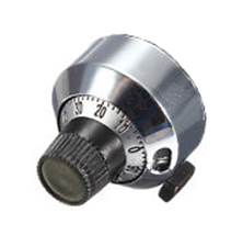
Figure 8-19. Counting dial for use with a multi-turn potentiometer
So where would a device like the one shown in Figures 8-17 and 8-18 be used? They are often found on test instruments and laboratory equipment. Ultrasonic metal crack detection equipment uses them, as do some medical devices. Basically, you’d use a multi-turn precision potentiometer wherever you need to be able to repeatedly set something to a relatively precise value or make a small precise adjustment to a circuit.
Surface-Mount Potentiometers
Surface-mount potentiometers and trimmers are internally the same as their larger cousins, only instead of PCB leads or a threaded barrel for mounting in a panel, these devices have small tabs or metalized areas that are soldered directly to the surface of a PCB. The types with extended leads are relatively easy to work with, but some types have the contact points under the body of the part, which can be difficult to solder manually.
Figure 8-20 shows two different types of trimmer potentiometers in surface-mount form. Be forewarned that these are tiny components, as shown in the relative scale diagram in Figure 8-21.
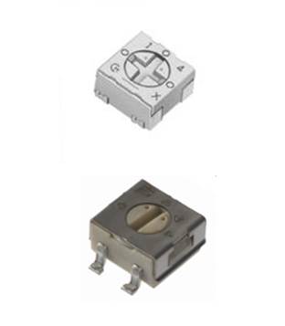
Figure 8-20. Surface-mount trimmer potentiometers
Figure 8-21 shows a 4.5 × 4.5 mm surface-mount trimmer potentiometer, a 1/4W resistor, and a US dime for size comparison. The surface-mount soldering technique described in Chapter 4 will work with these types of parts, but take care to ensure that solder paste or flux does not get into the part. The ones shown in Figure 8-20 are relatively well sealed, but other types have an open design and are susceptible to contamination.
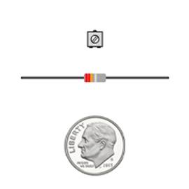
Figure 8-21. Relative size example for a surface-mount trimmer potentiometer
Figure 8-22 shows an example of a larger potentiometer in surface-mount form. This is more like the parts that you might mount in a panel or in a through-hole location on a PCB, except that it is designed to be surface-mounted and can be used with a pick-and-place machine for automated assembly.
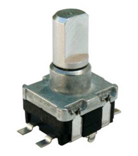
Figure 8-22. Large surface-mount potentiometer
Special-Purpose Resistors
Resistors can be made so that they are sensitive to certain aspects of their environment, including light, humidity, and temperature. These devices have been used in a variety of applications where low cost and simplicity are important considerations. On the other hand, they often don’t have the same level of precision and responsiveness of more expensive components. But if all the device needs to do is control a bathroom night light, measure the outside temperature and humidity, or determine if it is a sunny day or not, then a high level of precision probably isn’t necessary.
Temperature Sensitive
A temperature-sensitive resistor is commonly known as a thermistor. Although temperature sensitivity is also present in many types of common fixed-value resistors, it is intentionally enhanced in a thermistor, and thermistor devices can be manufactured so as to exhibit consistent response behavior.
Thermistors can be made with either a positive or negative temperature response coefficient. In other words, a positive temperature coefficient (PTC) device will exhibit increased resistance in response to increased temperature. A device with a negative temperature coefficient (NTC) will exhibit decreasing resistance with increasing temperature.
NTC thermistors are commonly used in temperature-sensing applications because they have a relatively linear response over a given temperature range. Figure 8-23 shows a small bead type of NTC thermistor used for temperature sensing.
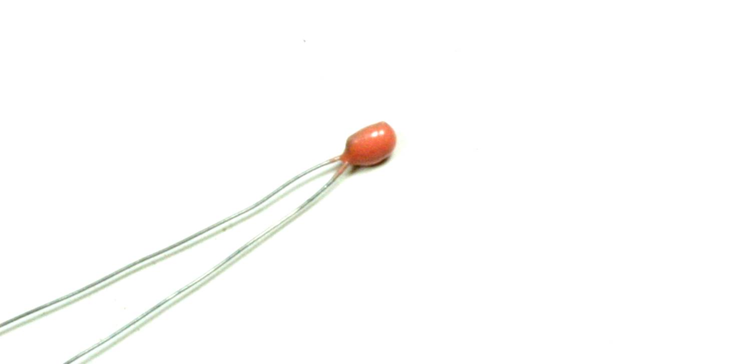
Figure 8-23. Small bead type of NTC thermistor
A PTC thermistor tends to act more like a switch, with a sudden increase in resistance once a certain specific temperature is reached. PTC-type thermistors are typically found as surge and inrush current protection devices.
Humidity Sensitive
The resistive humidity sensor, or humistor, is a type of resistor designed to respond to the amount of moisture in the gas surrounding it. A resistive humidity sensor measures the humidity level by measuring the change in the resistance of a hygroscopic element as it absorbs or releases moisture. The sensing element might be composed of an organic polymer (such as a polyamide resin, polyvinyl chloride, or polyethylene) or a metal oxide.
Light Sensitive
Light-sensitive resistors go by a variety of names, including photoresistor, photocell, or light-dependent resistor (LDR). A photoresistor works by decreasing its resistance in response to increasing light intensity. Figure 8-24 shows a typical cadmium sulphide (CdS photoresistor). These devices are cheap and readily available.
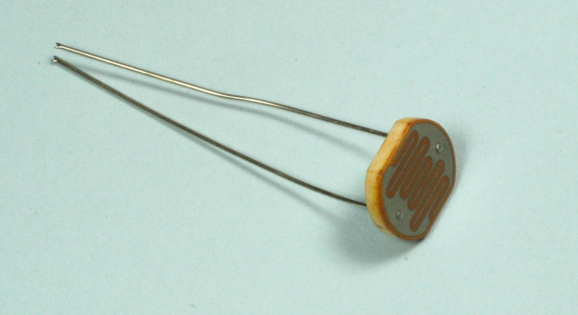
Figure 8-24. A typical CdS photoresistor component
Inexpensive CdS photoresistors can be found in many applications. They have been used as photographic light meters, both in handheld standalone devices and integrated directly into a camera. They can also be found in street lights, night lights, clock radios, and alarm systems.
A photoresistor is also useful in situations that don’t involve sensing ambient light levels. These include electronic devices where a small lamp is used to alter the resistance of the device without a direct electrical connection. Audio signal processing is a common application, and CdS photoresistors have also been used to couple control signals between high- and low-voltage sections of a system. If the response time of the photoresistor is short enough, it can be used to build a simple communications device. Figure 8-25 shows a couple of possible applications, which are both really just variations on a theme.
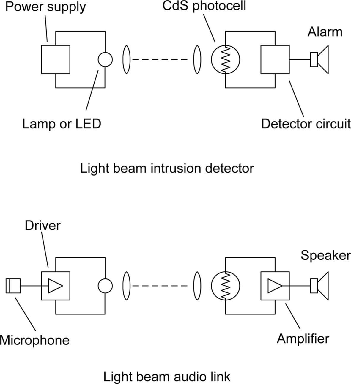
Figure 8-25. Two example applications for a CdS photocell device
Resistor Markings
The standard color code for nonprecision through-hole resistors consists of three to four color bands printed around the body of the part. As shown in Figure 8-26, the first two bands are the most significant digits, the third band is the multiplier (in 10× steps), and the fourth band, if present, indicates the tolerance of the part.
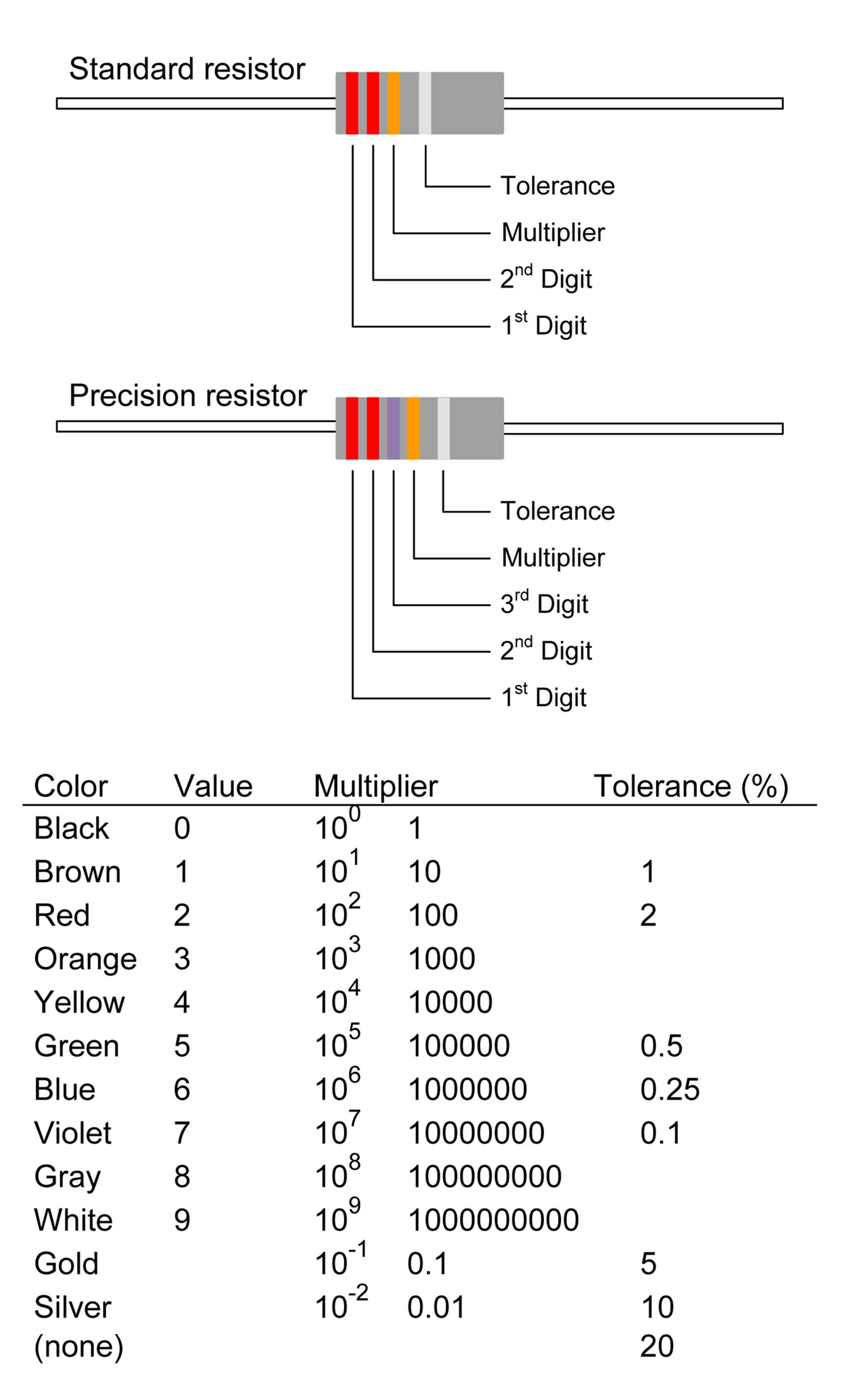
Figure 8-26. Standard resistor color codes
So if a carbon film resistor is marked with red, red, red, and gold, it is a 2,200 (2.2 k) ohm 5% part.
Precision resistors typically have a fifth band. In this case, the first three color bands are significant, with the third digit band for the decimal fraction part of the value. From this, we can see that a resistor with color bands orange, violet, red, orange, and green is a 47.2K with 0.5% tolerance.
Surface-mount resistors typically utilize numbers rather than colors. Standard parts (5 to 20% tolerance) will include three numbers. The first two are the significant digits, and the third is the multiplier. For example, a part marked with 474 is a 470,000 (470K) ohm resistor. In Figure 8-10, the resistor is marked with 681, which translates as 680 ohms.
There is one special type of resistor, which isn’t really a resistor at all: it’s a jumper that looks like a resistor, called a zero-ohm link. In the through-hole style, this will be a part with just a single black band. The surface-mount version has just a zero printed on it. These parts are mostly used in automated assembly systems, often because the machine that places the parts on the PCB for soldering can’t easily handle wire jumpers, or because the manufacturer doesn’t want or need to invest in a jumper-placing machine. If the zero-ohm link part is wide enough, one or more circuit traces may be safely routed under it without touching either of the part’s connecting pads.
Capacitors
A capacitor is a device that stores and releases electrical charge. You can think of it as a type of reservoir, or as an impermeable but flexible membrane. A capacitor does not allow direct current to flow, but it will allow alternating current to pass. The value of a capacitor depends on how much charge it can store, and it also has a direct bearing on how the capacitor will respond to an AC signal (see Appendix A for more details).
Capacitors are often used to couple one circuit section to another to allow only the desired signal to pass but block any residual DC that may be present. In digital logic circuits, they are often found connected between the Vcc (V+) pin of a TTL part to ground, and they are used to “decouple” the transient current spikes that can occur when a logic gate changes state. They are also used extensively in passive filter circuits to remove noise and 60 Hz ripples from the output of a DC power supply, and they show up in sensing circuits to help remove unwanted RF interference (RFI). Capacitors are used to build high-pass or low-pass filters, and they are an integral component in tuned circuits such as those used in radios.
Early capacitors were as simple as two metal plates separated by a small gap or a piece of oil-soaked paper. Later, they evolved into oil-filled canisters, or they were made from strips of foil separated by a layer of oil-impregnated paper. In any case, the concept is simple: two plates for accumulating charge are separated by some kind of dielectric material (i.e., an insulator that can be polarized). The surface area of the plates and the space separating them determines the overall capacitance of the device. Figure 8-27 is a generalized diagram of a capacitor.
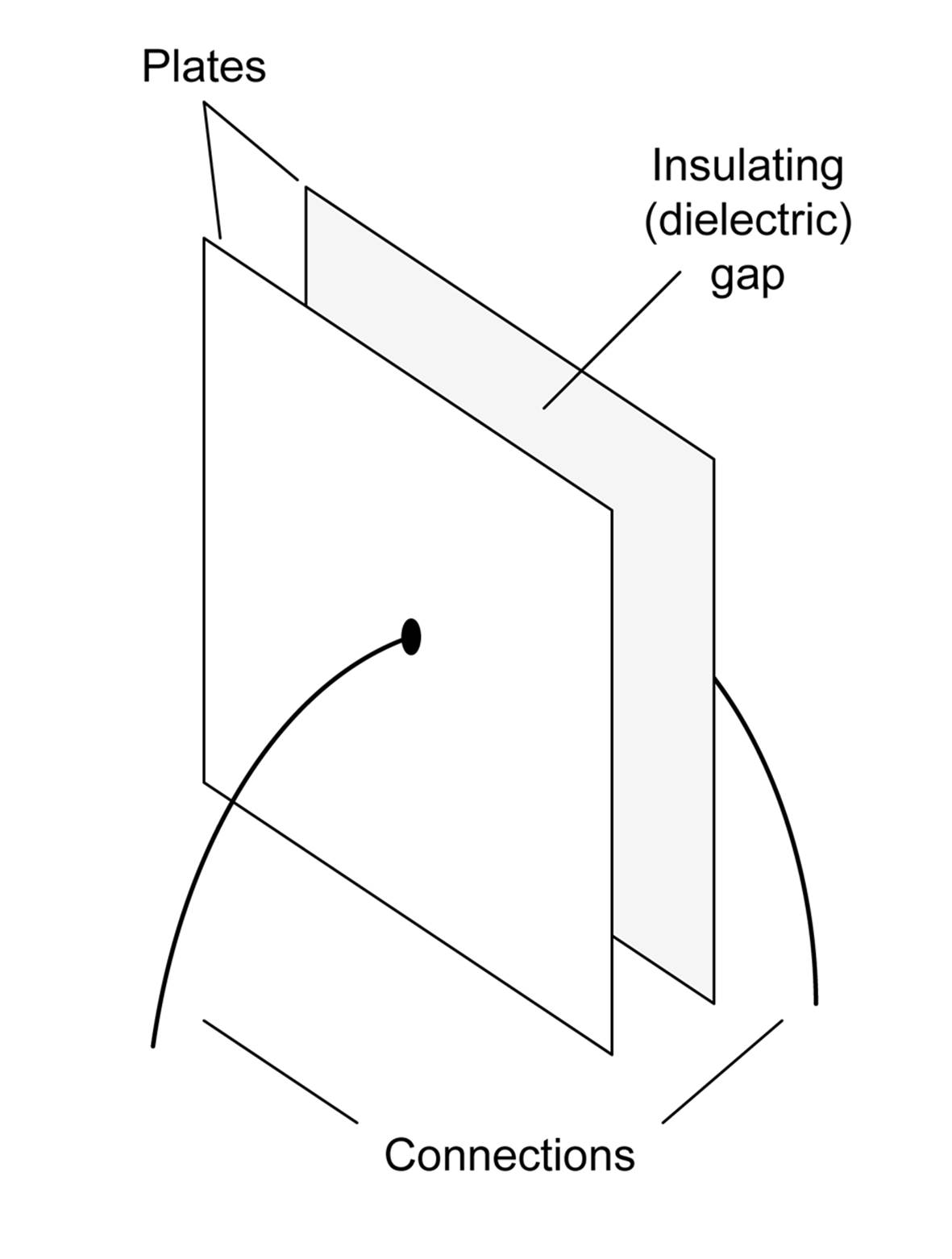
Figure 8-27. Generalized diagram of a capacitor
A capacitor stores energy in an electrostatic field that is generated by a potential difference across the plates. When a voltage is applied across a capacitor, one of the plates will accumulate a positive charge and the other will have an equal negative charge. The capacitance is largest when the distance between the plates is the smallest possible and the plate area is the largest possible. In other words, the capacitance increases as the area of the plates increases and the distance between them decreases.
There is a limit to how much of an electrical potential difference a capacitor can withstand before something breaks down. This is referred as the breakdown voltage. For some types of capacitors, this can be quite low, on the order of a few volts. Other types can withstand hundreds or even thousands of volts before breakdown occurs. The breakdown voltage limit is why electrolytic capacitors are specified with a maximum working voltage. Exceeding this voltage in operation courts disaster.
No capacitor is perfect, and after a charge is accumulated, it will immediately start to dissipate as soon as the potential source is removed. Capacitors with a dialectic made from polypropylene or polystyrene can exhibit extremely low leakage rates, whereas other types, such as electrolytics, tend to exhibit high leakage current.
Capacitance Values
Capacitance is measured in farads (after Michael Faraday), with 1 farad being defined as a capacitance that produces a potential difference of 1 volt after being charged by 1 ampere of current flowing for 1 second (which happens to be the same as 1 coulomb).
Most capacitors encountered in electronics have values measured in millifarads (mF), microfarads (μF), nanofarads (nF), or picofarads (pF). For example, the ceramic decoupling capacitors mentioned in the previous section are typically 0.1 μF types. Parts with very small values, in the pF range, are often found in RF circuits, while power supplies will employ capacitors with values of 470 μF or higher in the output filter section of the circuit.
Capacitor Types
Modern capacitors can be based on a ceramic dialectic, on thin layers of a plastic such as polyester, or on thin sheets of the mineral mica. Some types, such as electrolytic devices, use aluminum or tantalum foil and employ an oxide layer to serve as the dialectic. In these capacitors, an electrolyte paste serves as the second electrode.
Capacitors come in polarized and nonpolarized types. Electrolytic types are usually polarized, and you must be careful not to apply a reverse polarity voltage to the device. The results of this can be somewhat spectacular (e.g., an exploding part, smoke, a ball of fire, etc.).
A special class of electrolytic capacitors, called supercaps, is starting to appear as a backup power source for flash memory, and some supercaps are capable of storing enough energy to replace small batteries for short periods of time.
This section describes only ceramic, electrolytic, and plastic film capacitors. There are other types available, and some, like silver mica types, were once common but are now generally considered to be obsolete. A look through a distributor’s catalog will show you the wide variety of types and ratings available.
Ceramic
Ceramic capacitors are based on a ceramic wafer with a metal film applied to opposite sides. The area of the wafer and its thickness both work to determine the resulting capacitance of the part. Ceramic capacitors are inexpensive and relatively stable. Some types are large, such as disc forms, whereas others, like the monolithic types, can be very small. These types of capacitors are also available in surface-mount packages and share the same package numbering scheme as surface-mount resistors. Figure 8-28 shows both a disc and monolithic type of ceramic capacitor.
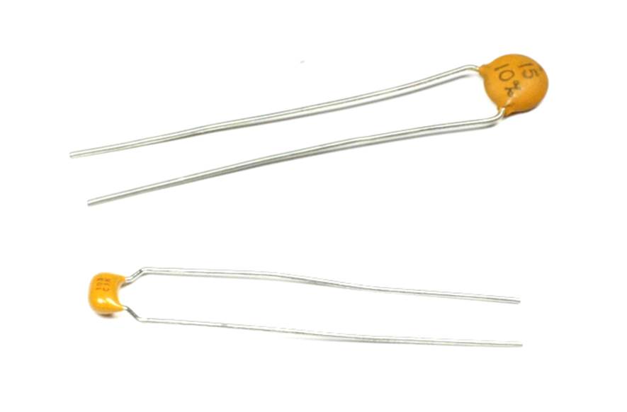
Figure 8-28. Ceramic capacitors
Most ceramic capacitors are marked using a three-digit scheme. The first two digits are significant and the third is the multiplier. Capacitors are marked in units of picofarads. Thus a part marked as 103 would be 10,000 pF, or 0.01 μF. Occasionally, you might come across an older ceramic capacitor that uses the color code shown in Figure 8-26, but these are rare nowadays.
Electrolytic
Electrolytic capacitors are capable of holding significantly more charge than other types, and for this reason they can often be found in power supplies and flash tube circuits. Electrolytic capacitors come in a variety of sizes and shapes, a sample of which is shown in Figure 8-29.
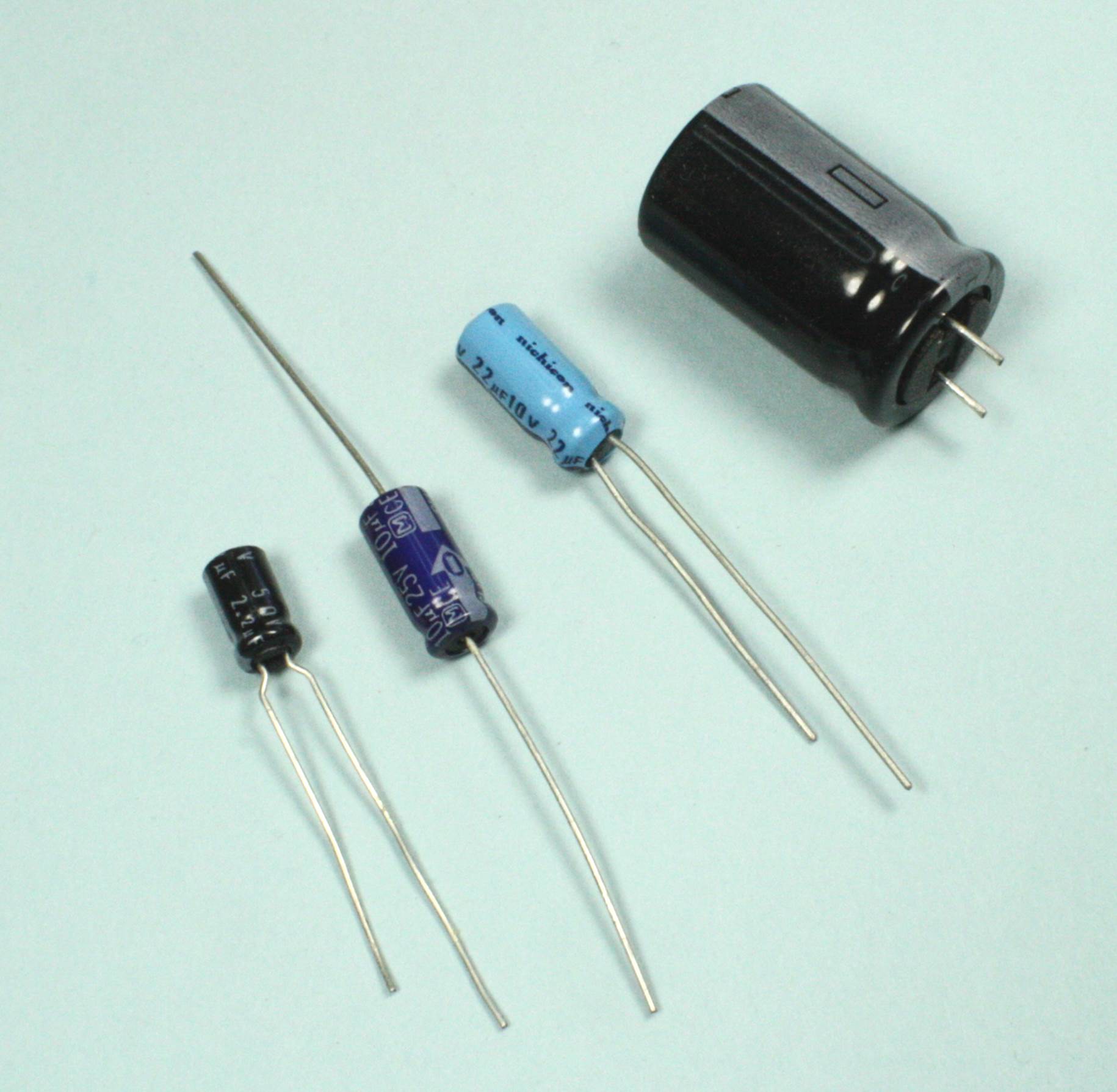
Figure 8-29. Some available electrolytic capacitor styles
Most electrolytic capacitors are polarized, so take care to make sure that a part isn’t installed incorrectly. These parts are available in both axial and radial forms, and there is also a surface-mount version of the metal-can electrolytic capacitor. The radial forms are common and readily available, but sometimes an axial lead component makes more sense for a design where the height above the PCB is constrained or when you might improve the design of the PCB by running traces under the body of an axial lead capacitor.
Tantalum eletrolytic capacitors are common in miniature electronic devices, mainly because they are more physically compact than a conventional electrolytic of the same value. They also exhibit better performance than conventional electrolytic types, but they are more expensive. Figure 8-30 shows a pair of typical tantalum capacitors with radial through-hole leads, but they are also available in axial packages and surface-mount packages.
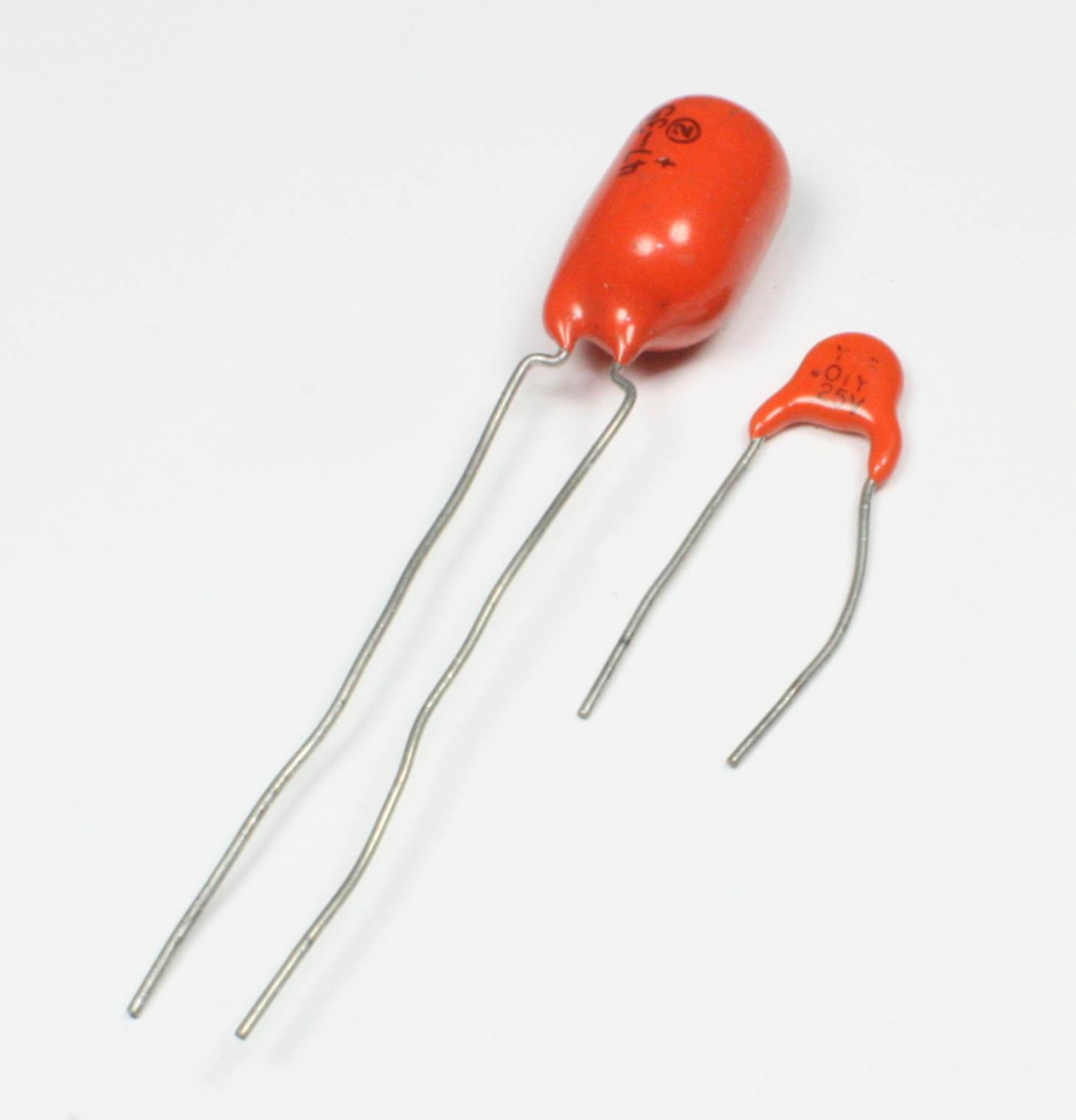
Figure 8-30. A generic example of a tantalum electrolytic capacitor
Plastic Film
As the name implies, plastic film capacitors utilize a thin plastic film as the dialectric material between the electrodes. Some common types of plastic used include polypropylene, polyester, polyenthylen naphthalate, polystyrene, and polycarbonate, to name just a few.
The primary advantages of a plastic film capacitor over a ceramic or electrolytic type are stability, low temperature dependence, and possibly a high capacitance value without being polarized. For this reason, they are often found in loudspeaker crossover filter circuits. These types of capacitors don’t appear very often in low-voltage electronics utilizing solid-state components.
Variable Capacitors
A variable capacitor is a rarity nowadays, but at one time, it was the primary means to alter the behavior of a tuned circuit. In other words, it was part of every radio receiver up until the late 20th century. As shown in Figure 8-31, a variable capacitor consists of a set of plates arranged such that one set can move in between another matching set. The extent to which the movable plates are within the fixed plates determines the capacitance.
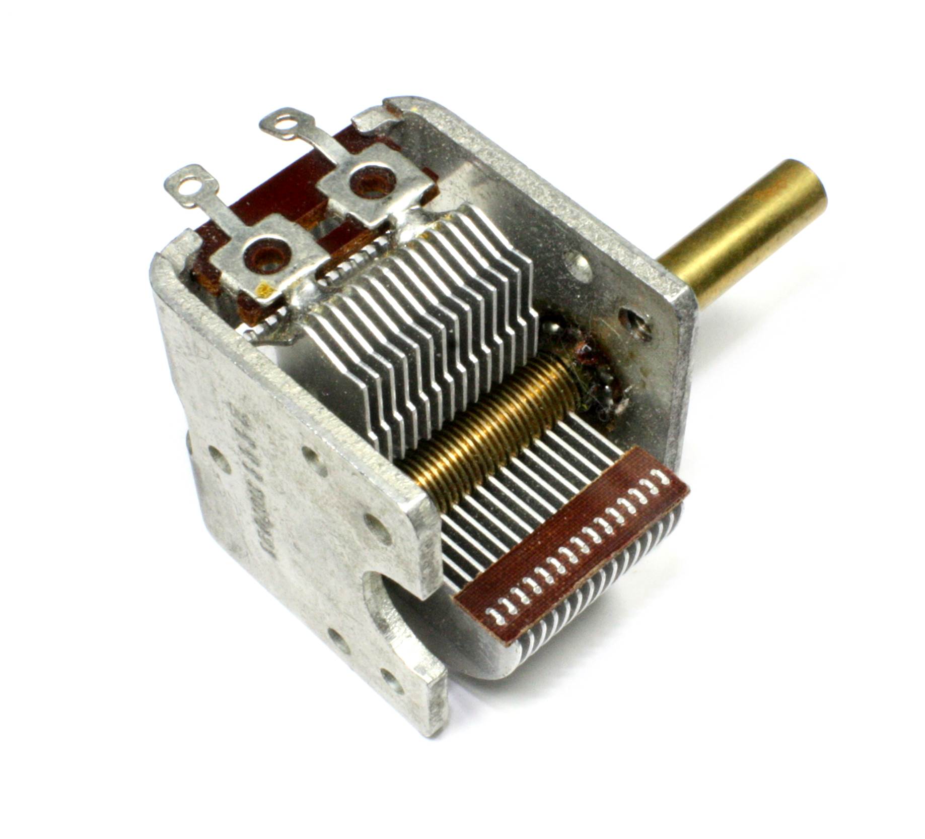
Figure 8-31. Variable capacitor for radio tuning
This type of capacitor is still used in some types of radio transmitting equipment, although it has been largely replaced by solid-state devices in modern radio receivers. Variable capacitors are also sometimes found in RF test equipment. Figure 8-32 shows a simple radio kit that uses a variable capacitor in the tuning circuit.
Figure 8-32. A simple AM/FM radio kit that uses a variable capacitor for tuning
Surface-Mount Capacitors
Surface-mount capacitors come in a range of sizes in rectangular packages similar to surface mount resistors. Some types are made with a can-type package, similar to the electrolytic capacitors shown in Figure 8-29, but with SMD mounting tabs or metalized areas rather than leads. Figure 8-33 shows some surface-mount electrolytic capacitors on a PCB.
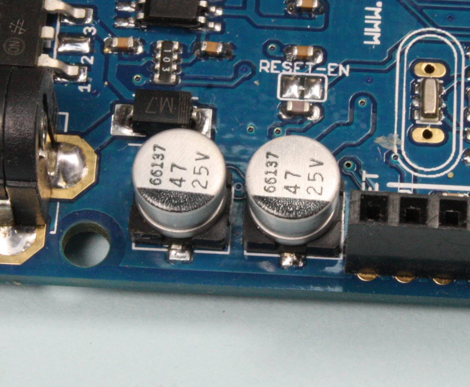
Figure 8-33. Surface-mount electrolytic capacitors
Figure 8-34 shows another example of surface-mount capacitors, in this case identifying some of the capacitors in an Arduino Leonardo.
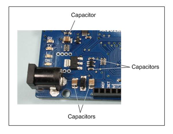
Figure 8-34. Surface-mount ceramic and tantalum capacitors on an Arduino Leonardo
Physically, a surface-mount capacitor can have a greater height than a resistor with the same length and width. This is particularly true for tantalum and electrolytic types.
Chokes, Coils, and Transformers
Inductors make up the third catagory of passive components and, like capacitors, they store and release energy, except that in the case of inductors, this is magnetic energy created by current flow through the inductor. Creating a magnetic field in an inductor requires electrical energy, and the inductor will initially oppose the incoming current and behaves like a load. When the initial current is removed, the collapsing magnetic field generates a current flow and the inductor behaves as a current source.
Recall that a capacitor will block DC but allow AC to pass. An inductor has the opposite behavior. An inductor impedes AC but does not impede DC, except for the inherent resistance of the wire in the inductor. In many cases, an inductor will appear like a short or an extremely low resistance to DC.
Inductors come in the form of chokes and coils. A choke uses a solid core of some type of ferromagnetic material—it is, in effect, a solenoid. A coil, on the other hand, is just an open coil of wire. The unit of measurement for an inductor, of any type, is the henry (abbreviated H), withcommon values being in the millihenry (mH) range.
This section is intended to provide only a quick look at inductors. For more on the theory behind inductors, refer to Appendix A.
Chokes
All inductors exhibit the property of resisting changes to the current passing through them, but chokes are designed to take advantage of that behavior. Chokes get their name from their applications in blocking AC while allowing DC to pass relatively unimpeded. Some types are specifically designed to block low-frequency signals, such as audio signals. Others are designed to block radio frequencies. The nodule sometimes found on computer cables contains a choke of some sort to help prevent interference from passing between a device and whatever it is connected to.Figure 8-35 shows a choke of the type that might be found in a power supply, or in series with the DC input to a circuit.
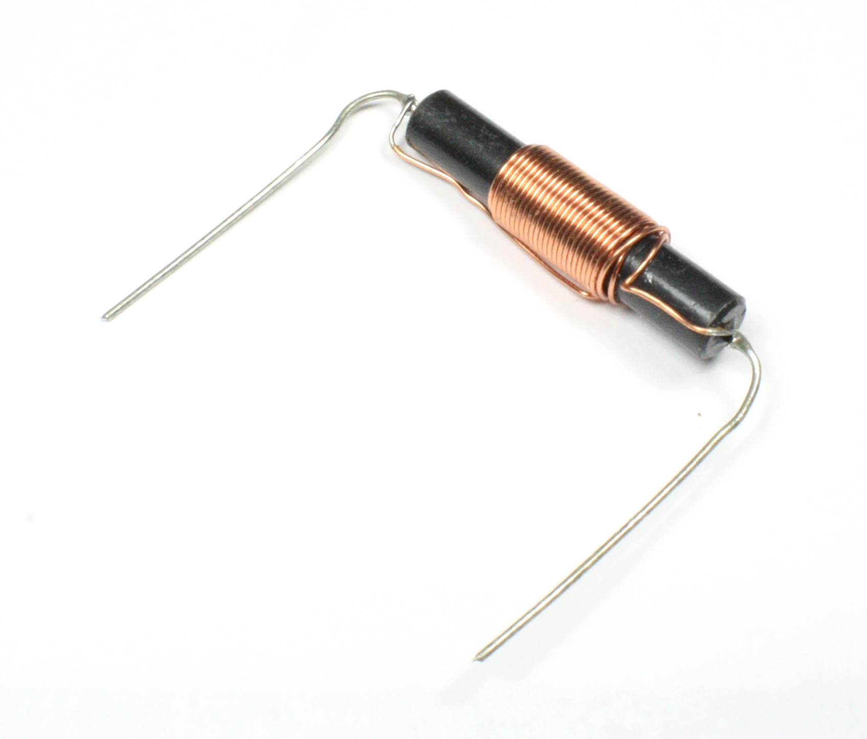
Figure 8-35. An RFI choke
Chokes come in a range of styles and ratings. They are useful when you are dealing with circuits that might be susceptible to external radio frequency interference on the power supply, or when you are attempting to take DC readings from a sensor connected to very long wires. Chokes also appear in the filter stage of linear power supplies to block the residual AC ripple from the rectifier section and help smooth the output.
Coils
A coil, otherwise known as just an inductor, is typically used to create a tuned circuit such as an oscillator or a radio receiver, although it sometimes assumes the role of coupling components between the sections of a circuit in radio equipment.
Although inductors are available in a selection of values, it is often the case that a coil must be constructed specifically for a particular application. Ham radio enthusiasts have been doing this for a long time, and texts like the ARRL Handbook (refer to Appendix C) contain formulas to use in order to determine the wire guage, diameter, and number of turns needed to construct a coil with a specific value. Figure 8-36 shows the tuning coil of a simple radio.
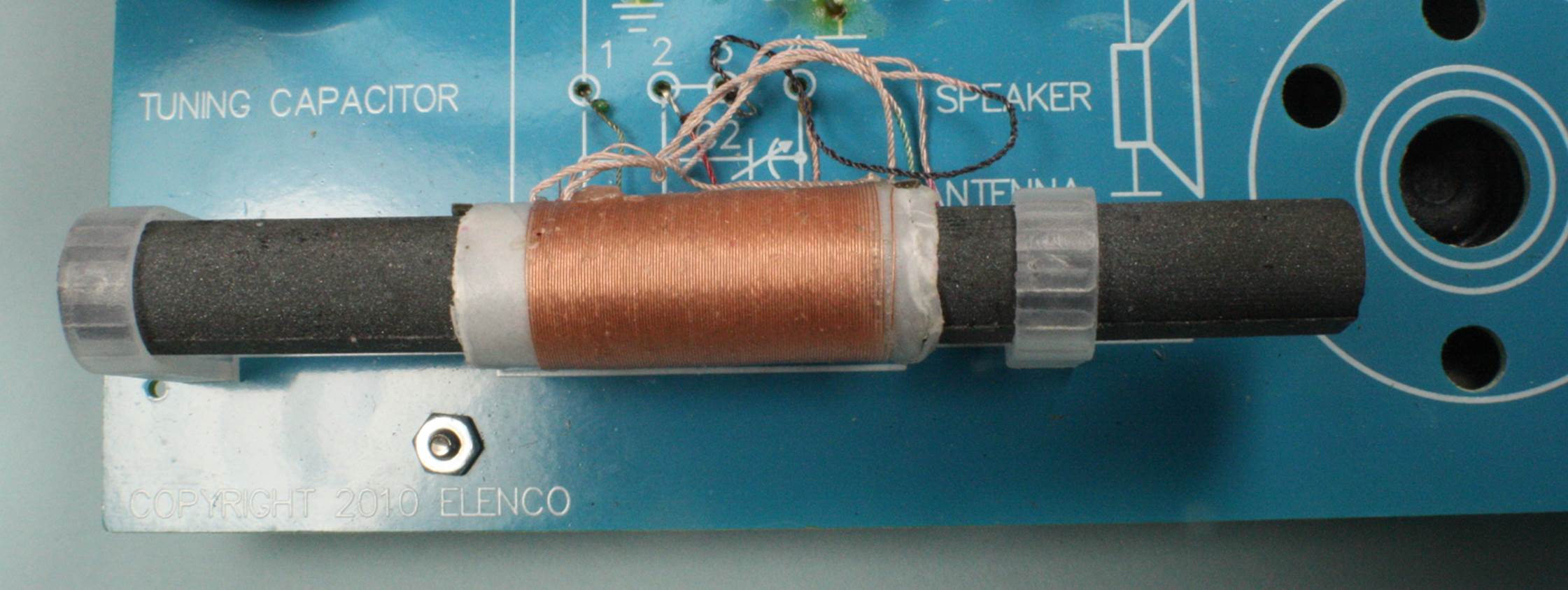
Figure 8-36. RF tuning coil for a simple radio circuit
For the most part, coils don’t show up much in electronics that don’t use radio frequency signals, except perhaps when a circuit needs to be filtered or tuned for a specific application.
Variable Inductors
Variable inductors are typically used in radio frequency applications. A common type of variable inductor contains a movable core, and you change the inductance by varying the depth of the core in the winding. When adjusting a variable inductor while the circuit is active, you use a nonmagnetic tool, somewhat like a plastic screwdriver, to keep from disturbing the behavior of the inductor. Figure 8-37 shows a common package type for a PCB-mounted variable inductor.
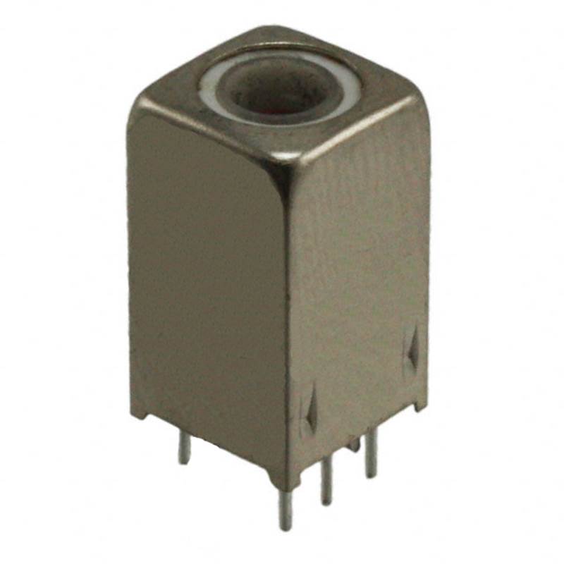
Figure 8-37. Typical PCB-mounted variable inductor
Transformers
A common example of an inductive device is the transformer. In a transformer, energy is inductively coupled from one winding to another. A transformer can reduce an input voltage to a lower level (a step-down transformer) or increase it (a step-up transformer). In a linear power supply, the incoming AC line voltage is reduced by using a smaller number of turns in the output winding than in the input winding. A step-up transformer is just the opposite. The ratio of input to output windings, the number of windings in each coil, and the material used for the core of the transformer determine its operating characteristics.
Other types of transformers are used to couple signals rather than transfer power. Audio transformers, as the name implies, are used to couple an audio signal from an input stage to an output stage. The transformer might be 1:1, which does not change the voltage level but does isolate one part of the ciruit from another.
Figure 8-38 shows a representative example of a small power transformer. The input winding, also called the primary winding, is rated for 230 VAC input. The output, or secondary, winding will produce 12.6 VAC (the secondary is actually center-tapped, so it can be used as two 6.3 VAC outputs). The core of the transformer is made up of layers of a material with high magnetic permeability to contain the magnetic field and improve inductive coupling between the windings.
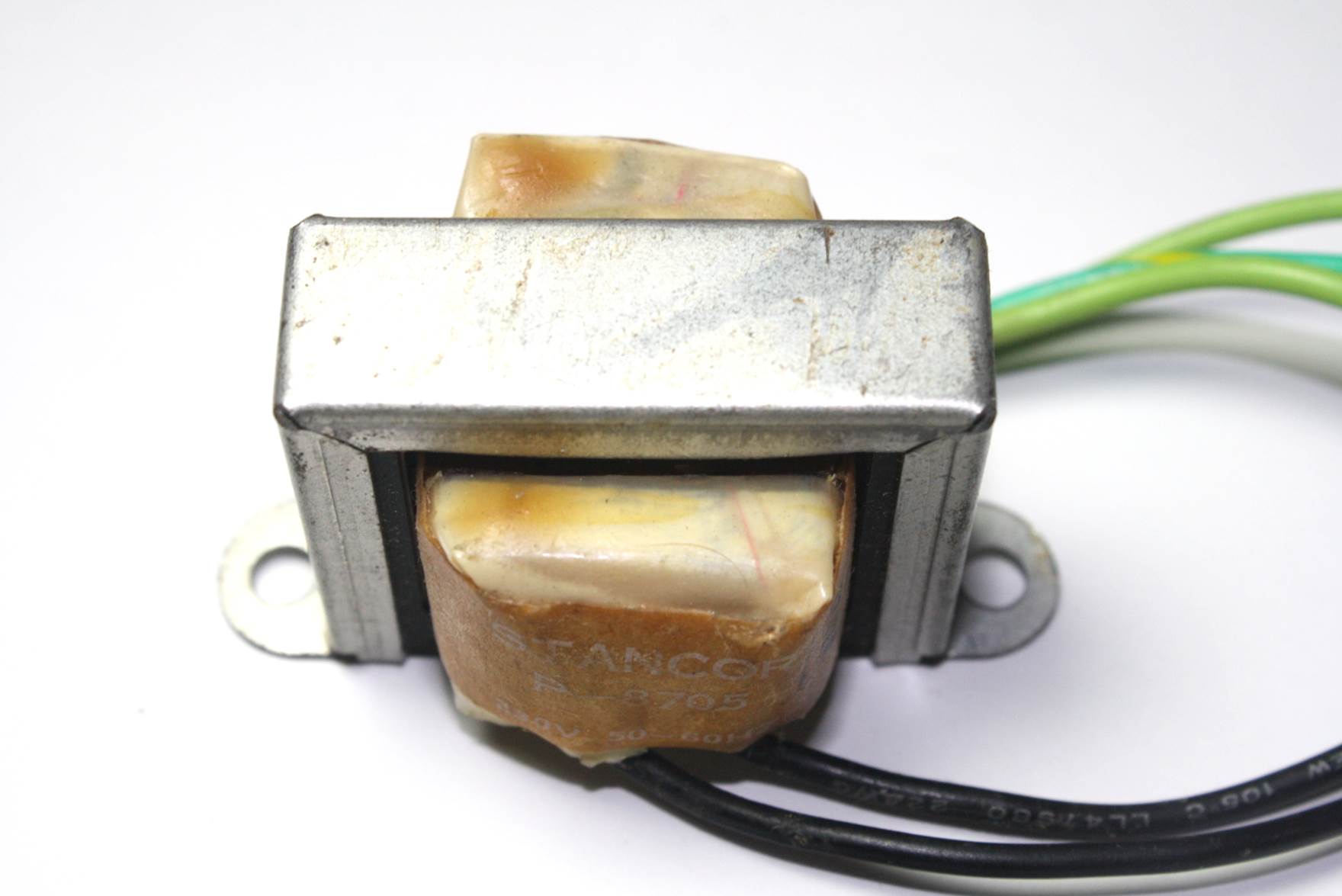
Figure 8-38. A typical small power transformer
Packages
As with resistors and capacitors, inductors and transformers are available in a variety of package styles. In addition to the axial choke shown in Figure 8-35, inductors are availabe in small axial lead packages not much larger than a 1/2 watt resistor, in radial lead packages that resemble electrolytic capacitors, and in surface-mount packages. Some SMD inductors look like surface-mount capacitors or large resistors, while others have a square shape and a circular internal coil form to hold the wound wire. Transformers are available in chassis-mounted styles like the one shown in Figure 8-38, compact packages with leads for through-hole PCB mounting, and as surface-mount parts.
Summary
This chapter covered the three primary types of passive linear circuit components: resistors, capacitors, and inductors. Of these, resistors and capacitors are the components that will be the most commonly used in low-voltage analog circuits and microcontroller applications. Inductors might come into play for RFI suppression and will definitely be useful when you are dealing with RF circuits.
Passive components such as fixed resistors and capacitors come in one of three basic physical forms: axial, radial, and surface-mount. Variable resistors can take either a rotary or linear form, and variable capacitors are commonly built around a rotary mechanism.
What we haven’t covered are large electrolytic capacitors, such as the types used in heavy-duty linear power supplies. The rise of switching power supplies has largely eliminated the need for capacitors the size of soup cans, although they can still be purchased. If you ever get the chance to strip down an old mini or mainframe computer system from the 1960s or 1970s, you will see these in the DC power supplies. However, electrolytic capacitors that are 30 years old probably aren’t good any longer, since the internal electrolyte will likely be dried out.
We also didn’t cover all the capacitor types available, such as mica and some of the plastic dielectric-based components. These are not commonly used with digital electronics or sensing circuits. They are more commonly encountered with low-noise audio, RF, and some types of laboratory-grade precision circuits that need the low noise and thermal stability they can provide.
Each of the three passive component types comes in a vast array of physical sizes, physical compositions, and electrical ratings. Each one would deserve its own book to really do it justice. Fortunately, those books have already been written, and some of them are listed in Appendix C. A look through the catalog of a major distributor or a search on the Web will reveal a massive amount of information, most of it free. Hopefully, with the overview provided by this chapter, you should be able to make some sense of this information.
All materials on the site are licensed Creative Commons Attribution-Sharealike 3.0 Unported CC BY-SA 3.0 & GNU Free Documentation License (GFDL)
If you are the copyright holder of any material contained on our site and intend to remove it, please contact our site administrator for approval.
© 2016-2026 All site design rights belong to S.Y.A.