Programming 3D Applications with HTML5 and WebGL (2013)
Part I. Foundations
Chapter 2. WebGL: Real-Time 3D Rendering
WebGL is the standard 3D graphics API for the Web. It allows developers to harness the full power of the computer’s 3D rendering hardware from within the browser using JavaScript. Before WebGL, developers had to rely on plugins or native applications and ask their users to download and install custom software in order to deliver a hardware-accelerated 3D experience.
While WebGL is not in the official HTML5 specification, it is shipped with most browsers that support HTML5. Like Web Workers, WebSockets, and other technologies outside the official W3C recommendations, WebGL comes with the package; the developers at Google, Apple, Mozilla, Microsoft, Amazon, Opera, Intel, and BlackBerry consider 3D an essential component for making the browser into a first-class application platform.
WebGL works on the majority of desktops, and almost all mobile browsers.[1] There are millions of WebGL-enabled seats already installed, most likely including the machines you run at home and in your office. There are numerous sites under development, with applications including games, data visualization, computer-aided design, 3D printing, and consumer retail.
WebGL is a low-level drawing API: you supply it with arrays of data and a shader, and tell it to draw. Anyone used to a graphics API like the 2D Canvas will find the lack of high-level constructs mystifying at first. However, there are several open source JavaScript toolkits that provider higher-level access to the API to make it look more like a traditional drawing library. Even with a toolkit, 3D is still hard work, but these tools at least make it approachable for folks with limited 3D development experience; and for experienced 3D developers, they are big time savers.
In this chapter we will take a quick tour of the low-level underpinnings of WebGL to give you a foundation. For the majority of the book we will be using toolkit software that hides most of the API details. But it is important to know what these tools are built upon, so let’s start by exploring WebGL’s core concepts and API.
NOTE
As with many of the newer HTML5 features, WebGL may not be supported on your computer. WebGL is supported in all major desktop browsers, but for some browsers this is only in newer versions (such as version 11 of Internet Explorer). Also, there are certain older machine configurations that do not have the requisite graphics processor to perform hardware-accelerated 3D, and for those, the browsers “blacklist” WebGL (i.e., turn it off). If you want to get an idea if your target machines, devices, and/or browsers support WebGL, try the reference site http://caniuse.com/ and type in the search term “WebGL,” or hit the WebGL test directly via http://caniuse.com/#search=WebGL.
WebGL Basics
WebGL grew out of experiments in 2006 by Mozilla engineer Vladimir Vukićević. Vukićević wanted to create a 3D drawing API for the Canvas element, to parallel the existing 2D Canvas API. He wisely based his design, called Canvas 3D, on OpenGL ES, the API standard that had been steadily gaining popularity for mobile graphics development. By 2007, there were independent implementations of Canvas 3D in both the Mozilla and Opera browsers.
In 2009, Vukićević was joined by participants from Opera, Apple, and Google to create the WebGL Working Group within the Khronos Group, the standards body that also governs OpenGL, COLLADA, and other specifications you may have heard of. Khronos continues to maintain the WebGL specification to this day. Vukićević served as the original chair of the working group, until 2010, when Kenneth Russell of Google assumed the role.
Here is the official description of WebGL, from the Khronos website:
WebGL is a royalty-free, cross-platform API that brings OpenGL ES 2.0 to the web as a 3D drawing context within HTML, exposed as low-level Document Object Model interfaces. It uses the OpenGL shading language, GLSL ES, and can be cleanly combined with other web content that is layered on top or underneath the 3D content. It is ideally suited for dynamic 3D web applications in the JavaScript programming language, and will be fully integrated in leading web browsers.
This definition comprises several core ideas. Let’s deconstruct them here.
§ WebGL is an API. WebGL is accessed exclusively through a set of JavaScript programming interfaces; there are no accompanying tags like there are with HTML. 3D rendering in WebGL is analogous to 2D drawing using the Canvas element, in that it is all done through JavaScript API calls. In fact, access to WebGL is provided via the existing Canvas element and through a special drawing context specific to WebGL.
§ WebGL is based on OpenGL ES 2.0. OpenGL ES is an adaptation of the long-established 3D rendering standard OpenGL. The ES stands for “embedded systems,” meaning that it has been tailored for use in small computing devices, most notably phones and tablets. OpenGL ES is the API that powers 3D graphics for iPhone, iPad, Android phones, and Android tablets. WebGL’s designers felt that basing the API on OpenGL ES’s small footprint would make it easier to deliver a consistent, cross-platform, cross-browser 3D API for the Web.
§ WebGL combines with other web content. WebGL layers on top of or underneath other page content. The 3D canvas can take up just a portion of the page, or the whole page. It can reside inside <div> tags that are z-ordered. This means that you develop your 3D graphics using WebGL, but you build all your other elements using familiar old HTML. The browser composites (combines) all of the graphics on the page into a seamless experience for the user.
§ WebGL is built for dynamic web applications. WebGL has been designed with web delivery in mind. WebGL starts with OpenGL ES, but it has been adapted with specific features that integrate well with web browsers, work with the JavaScript language, and are friendly for web delivery.
§ WebGL is cross-platform. WebGL is capable of running on any operating system, on devices ranging from phones and tablets to desktop computers.
§ WebGL is royalty-free. Like all open web specifications, WebGL is free to use. Nobody will be asking you to pay royalties for the privilege.
The makers of Chrome, Firefox, Safari, and Opera have committed significant resources to developing and supporting WebGL, and engineers from these teams are also key members of the working group that develops the specification. The WebGL specification process is open to all Khronos members, and there are also mailing lists open to the public. See the Appendix for a list of mailing lists and other specification resources.
The WebGL API
WebGL is based on the long-established graphics API known as OpenGL. Originally developed in the late 1980s, OpenGL has been an industry-standard API for a very long time, having endured competitive threats from Microsoft DirectX to emerge as the undisputed standard for programming 3D graphics.
But not all OpenGLs are the same. The characteristics of various platforms—including desktop computers, set-top televisions, smartphones, and tablets—are so divergent that different editions of OpenGL had to be developed. OpenGL ES is the version of OpenGL developed to run on small devices such as set-top TVs and smartphones. Perhaps unforeseen at the time of its development, it turns out the OpenGL ES forms the ideal core for WebGL. It is small and lean, which means that not only is it (relatively) straightforward to implement in a browser, but it also makes it much more likely that the developers of the different browsers implement it consistently, and that a WebGL application written for one browser will work identically in another browser.
The lean nature of WebGL puts the onus on application developers to do a lot of work. There is no DOM representation of the 3D scene; there are no natively supported 3D file formats for loading geometry and animations; and with the exception of a few low-level system events, there is no built-in event model to report the goings-on within the 3D canvas (e.g., no mouse-click events telling you what object was clicked on). To the average web developer, WebGL represents a steep learning curve full of truly alien concepts.
The good news here is that there are several open source code libraries out there that make WebGL development approachable. Think of them as existing at the level of jQuery or Prototype.js, though the analogy is rough at best. We will be talking about these libraries in the next few chapters. But right now, we are going to take a quick tour of the underpinnings, the drivetrain if you will, of WebGL. Even if you never write low-level WebGL for your projects, it’s good to know what’s happening under the hood.
The Anatomy of a WebGL Application
At the end of the day, WebGL is just a drawing library—another kind of canvas, akin to the 2D Canvas supported in all HTML5 browsers. In fact, WebGL actually uses the HTML5 Canvas element to get 3D graphics into the browser page.
In order to render WebGL into a page, an application must, at a minimum, perform the following steps:
1. Create a Canvas element.
2. Obtain a drawing context for the canvas.
3. Initialize the viewport.
4. Create one or more buffers containing the data to be rendered (typically vertices).
5. Create one or more matrices to define the transformation from vertex buffers to screen space.
6. Create one or more shaders to implement the drawing algorithm.
7. Initialize the shaders with parameters.
8. Draw.
Let’s look at a few examples to illustrate this flow.
A Simple WebGL Example
To illustrate the basic workings of the WebGL API, we are going to write very simple code that draws a single white square on the canvas. See the file Chapter 2/example2-1.html for a full code listing. The result is shown in Figure 2-1.

Figure 2-1. A square drawn with WebGL
NOTE
The samples in this section are heavily inspired by the lessons at Learning WebGL, a wonderful site that was originally developed by Giles Thomas. Learning WebGL is a fantastic resource for getting to know the WebGL API through tutorials. The site also features a weekly roundup of new WebGL applications, so it is a good place to keep abreast of the latest developments.
The Canvas Element and WebGL Drawing Context
All WebGL rendering takes place in a context, a browser DOM object that provides the complete WebGL API. This structure mirrors the 2D drawing context provided in the HTML5 Canvas element. To get WebGL into your web page, create a <canvas> tag somewhere on the page, get the DOM object associated with it (say, using document.getElementById()), and then get a WebGL context for it.
Example 2-1 shows how to get the WebGL context from a canvas DOM element. The getContext() method can take one of the following context id strings: "2d" for a 2D Canvas context (covered in Chapter 7), "webgl" for a WebGL context, or "experimental-webgl" to get a WebGL context for earlier-version browsers. The "experimental-webgl" style is still supported in newer browsers, even if they also support "webgl", so we will use that to make sure we can get a context for all WebGL-capable browsers.
Example 2-1. Obtaining a WebGL context from a canvas
function initWebGL(canvas) {
var gl = null;
var msg = "Your browser does not support WebGL, " +
"or it is not enabled by default.";
try
{
gl = canvas.getContext("experimental-webgl");
}
catch (e)
{
msg = "Error creating WebGL Context!: " + e.toString();
}
if (!gl)
{
alert(msg);
throw new Error(msg);
}
return gl;
}
NOTE
Note the try/catch block in the example. This is very important, because some browsers still do not support WebGL, or even if they do, the user may not have the most recent version of that browser that includes WebGL support. Further, even browsers that do support WebGL may be running on old hardware, and may not be able to give you a valid WebGL rendering context. So, detection code like the preceding will help you with deploying a fallback such as a rendering based on a 2D canvas—or, at the very least, provide you with a graceful exit.
The Viewport
Once you have obtained a valid WebGL drawing context from your canvas, you need to tell it the rectangular bounds of where to draw. In WebGL this is called a viewport. Setting the viewport in WebGL is simple; just call the context’s viewport() method, as shown in Example 2-2.
Example 2-2. Setting the WebGL viewport
function initViewport(gl, canvas)
{
gl.viewport(0, 0, canvas.width, canvas.height);
}
Recall that the gl object used here was created by our helper function initWebGL(). In this case we have initialized the WebGL viewport to take up the entire contents of the canvas’s display area.
Buffers, ArrayBuffer, and Typed Arrays
Now, we have a context ready for drawing. This is pretty much where the similarities to 2D Canvas end.
WebGL drawing is done with primitives—different types of objects to draw. WebGL primitive types include triangles, points, and lines. Triangles, the most commonly used primitive, are actually accessible in two different forms: as triangle sets (arrays of triangles) and triangle strips (described shortly). Primitives use arrays of data, called buffers, which define the positions of the vertices to be drawn.
Example 2-3 shows how to create the vertex buffer data for a unit (1×1) square. The results are returned in a JavaScript object containing the vertex buffer data, the size of a vertex structure (in this case, three floating-point numbers to store x, y, and z), the number of vertices to be drawn, and the type of primitive that will be used to draw the square—in this example, a triangle strip. A triangle strip is a rendering primitive that defines a sequence of triangles using the first three vertices for the first triangle, and each subsequent vertex in combination with the previous two for subsequent triangles.
Example 2-3. Creating vertex buffer data
// Create the vertex data for a square to be drawn
function createSquare(gl) {
var vertexBuffer;
vertexBuffer = gl.createBuffer();
gl.bindBuffer(gl.ARRAY_BUFFER, vertexBuffer);
var verts = [
.5, .5, 0.0,
-.5, .5, 0.0,
.5, -.5, 0.0,
-.5, -.5, 0.0
];
gl.bufferData(gl.ARRAY_BUFFER, new Float32Array(verts), gl.STATIC_DRAW);
var square = {buffer:vertexBuffer, vertSize:3, nVerts:4,
primtype:gl.TRIANGLE_STRIP};
return square;
}
Note the use of the type Float32Array. This is a new data type introduced into web browsers for use with WebGL. Float32Array is a type of ArrayBuffer, also known as a typed array. This is a JavaScript type that stores compact binary data. You can access typed arrays from JavaScript using the same syntax as ordinary arrays, but they are much faster and consume less memory. They are ideal for use with binary data where performance is critical. Typed arrays can be put to general use, but their introduction into web browsers was pioneered by the WebGL effort. The latest typed array specification can be found on the Khronos website.
Matrices
Before we can draw the square, we must create a couple of matrices. First, we need a matrix to define where the square is positioned in our 3D coordinate system, relative to the camera. This is known as a ModelView matrix, because it combines transformations of the model (3D mesh) and the camera. In our example, we are transforming the square by translating it along the negative z-axis (i.e., moving it away from the camera by −3.333 units). The second matrix we need is the projection matrix, which will be required by our shader to convert the 3D space coordinates of the model in camera space into 2D coordinates drawn in the space of the viewport. In this example, the projection matrix defines a 45-degree field-of-view perspective camera. (For a refresher on perspective projections, see the discussion in Chapter 1.)
In WebGL, matrices are represented simply as typed arrays of numbers; for example, a 4×4 matrix has a Float32Array of 16 elements. To help us with setting up and manipulating our matrices, we are using a great open source library called glMatrix, written by Brandon Jones, now an engineer at Google. The matrix setup code is shown in Example 2-4. glMatrix matrices are of type mat4, created via the factory function mat4.create(). The function initMatrices() creates the model view and projection matrices and stores them in the global variablesmodelViewMatrix and projectionMatrix, respectively.
Example 2-4. Setting up the projection and ModelView matrices
var projectionMatrix, modelViewMatrix;
function initMatrices(canvas)
{
// Create a model view matrix with camera at 0, 0, −3.333
modelViewMatrix = mat4.create();
mat4.translate(modelViewMatrix, modelViewMatrix, [0, 0, −3.333]);
// Create a project matrix with 45 degree field of view
projectionMatrix = mat4.create();
mat4.perspective(projectionMatrix, Math.PI / 4,
canvas.width / canvas.height, 1, 10000);
}
The Shader
We are almost ready to draw our scene. There is one more important piece of setup: the shader. As described earlier, shaders are small programs written in GLSL (a high-level C-like language) that define how the pixels for 3D objects actually get drawn on the screen. WebGL requires the developer to supply a shader for each object that gets drawn. The shader can be used for multiple objects, so in practice it is often sufficient to supply one shader for the whole application, reusing it with different geometry and parameter values each time.
A shader is typically composed of two parts: the vertex shader and the fragment shader (also known as the pixel shader). The vertex shader is responsible for transforming the coordinates of the object into 2D display space; the fragment shader is responsible for generating the final color output of each pixel for the transformed vertices, based on inputs such as color, texture, lighting, and material values. In our simple example, the vertex shader combines the vertexPos, modelViewMatrix, and projectionMatrix values to create the final, transformed vertex for each input, and the fragment shader simply outputs a hardcoded white color.
In WebGL, shader setup requires a sequence of steps, including compiling the individual pieces from GLSL source code, then linking them together. Example 2-5 lists the shader code. Let’s walk through it. First, we define a helper function, createShader(), that uses WebGL methods to compile the vertex and fragment shaders from source code.
Example 2-5. The shader code
function createShader(gl, str, type) {
var shader;
if (type == "fragment") {
shader = gl.createShader(gl.FRAGMENT_SHADER);
} else if (type == "vertex") {
shader = gl.createShader(gl.VERTEX_SHADER);
} else {
return null;
}
gl.shaderSource(shader, str);
gl.compileShader(shader);
if (!gl.getShaderParameter(shader, gl.COMPILE_STATUS)) {
alert(gl.getShaderInfoLog(shader));
return null;
}
return shader;
}
The GLSL source code is supplied as JavaScript strings that we define as the global variables vertexShaderSource and fragmentShaderSource:
var vertexShaderSource =
" attribute vec3 vertexPos;\n" +
" uniform mat4 modelViewMatrix;\n" +
" uniform mat4 projectionMatrix;\n" +
" void main(void) {\n" +
" // Return the transformed and projected vertex value\n" +
" gl_Position = projectionMatrix * modelViewMatrix * \n" +
" vec4(vertexPos, 1.0);\n" +
" }\n";
var fragmentShaderSource =
" void main(void) {\n" +
" // Return the pixel color: always output white\n" +
" gl_FragColor = vec4(1.0, 1.0, 1.0, 1.0);\n" +
"}\n";
NOTE
The GLSL source code is supplied as JavaScript strings stored in global variables. This is a bit ugly, as we have to concatenate strings separated by newlines to construct the source. As an alternative, we could have defined the shader in external text files and loaded them via Ajax; or we could have created hidden DOM elements and tucked the source into their textContent. We did it this way for the example so that we could keep things simple for now. In your code you might consider using one of the other, more elegant schemes.
Once the parts of the shader have been compiled, we need to link them together into a working program using the WebGL methods gl.createProgram(), gl.attachShader(), and gl.linkProgram(). Once linking is successful, we have to do one more thing before we are ready to use the shader program: obtain a handle to each of the variables defined in the GLSL shader code so that they can be initialized with values from the JavaScript code. We do this using the WebGL methods gl.getAttribLocation() and gl.getUniformLocation(). TheinitShader() function is defined in the following code:
var shaderProgram, shaderVertexPositionAttribute,
shaderProjectionMatrixUniform,
shaderModelViewMatrixUniform;
function initShader(gl) {
// load and compile the fragment and vertex shader
var fragmentShader = createShader(gl, fragmentShaderSource,
"fragment");
var vertexShader = createShader(gl, vertexShaderSource,
"vertex");
// link them together into a new program
shaderProgram = gl.createProgram();
gl.attachShader(shaderProgram, vertexShader);
gl.attachShader(shaderProgram, fragmentShader);
gl.linkProgram(shaderProgram);
// get pointers to the shader params
shaderVertexPositionAttribute =
gl.getAttribLocation(shaderProgram, "vertexPos");
gl.enableVertexAttribArray(shaderVertexPositionAttribute);
shaderProjectionMatrixUniform =
gl.getUniformLocation(shaderProgram, "projectionMatrix");
shaderModelViewMatrixUniform =
gl.getUniformLocation(shaderProgram, "modelViewMatrix");
if (!gl.getProgramParameter(shaderProgram,
gl.LINK_STATUS)) {
alert("Could not initialise shaders");
}
}
Drawing Primitives
Now, we are ready to draw our square. Our context has been created; our viewport has been set; our vertex buffer, matrices, and shaders have been created and initialized. We define a function, draw(), which takes the WebGL context and our previously created square object. Let’s walk through this function.
First, draw() clears the canvas with a black background color. The method gl.clearColor() sets the current clear color to black. This method takes a four-component RGBA (red, green, blue, alpha). Note that WebGL’s RGBA values are floating-point numbers in the range 0.0 to 1.0 (in contrast to the integer range 0 to 255 used for web color values, e.g., in CSS). Then, gl.clear() uses the clear color to clear the WebGL color buffer; that is, the area in GPU memory used to render the bits on the screen. (WebGL uses several types of buffers for drawing, including the color buffer and a depth buffer for depth testing, which we will look at in the next section.)
Next, our draw() function sets (binds) the vertex buffer for the square to be drawn, sets (uses) the shader that will be executed to draw the primitive, and connects the vertex buffer and matrices to the shader as inputs. Finally, we call the WebGL drawArrays() method to draw the square. We simply tell it which type of primitive and how many vertices in the primitive; WebGL knows everything else already because we have previously set those other items (vertices, matrices, shaders) as state in the context. See the listing in Example 2-6.
Example 2-6. The drawing code
function draw(gl, obj) {
// clear the background (with black)
gl.clearColor(0.0, 0.0, 0.0, 1.0);
gl.clear(gl.COLOR_BUFFER_BIT);
// set the vertex buffer to be drawn
gl.bindBuffer(gl.ARRAY_BUFFER, obj.buffer);
// set the shader to use
gl.useProgram(shaderProgram);
// connect up the shader parameters: vertex position
// and projection/model matrices
gl.vertexAttribPointer(shaderVertexPositionAttribute,
obj.vertSize, gl.FLOAT, false, 0, 0);
gl.uniformMatrix4fv(shaderProjectionMatrixUniform, false,
projectionMatrix);
gl.uniformMatrix4fv(shaderModelViewMatrixUniform, false,
modelViewMatrix);
// draw the object
gl.drawArrays(obj.primtype, 0, obj.nVerts);
}
And that—at long last—is it. The result is a white square drawn against a black background, depicted back in Figure 2-1.
Creating 3D Geometry
The square was about as simple a WebGL example as we can contrive. Obviously, it’s not very interesting—it’s not even 3D—yet it clocks in at nearly 200 lines of code. The corresponding 2D Canvas drawing code would be around 30 lines at most. At this point it’s clearly not a win over using other drawing APIs. But here is where it gets interesting. Now we are going to use WebGL to do true 3D drawing. We’ll need a few extra lines of code to create the geometry for a 3D cube with multiple colors, and we will have to make a few small changes to the shader and the drawing function. We are also going to throw in a simple animation so that we can see the cube from all sides. Figure 2-2 shows a screenshot of the cube in mid-rotation.
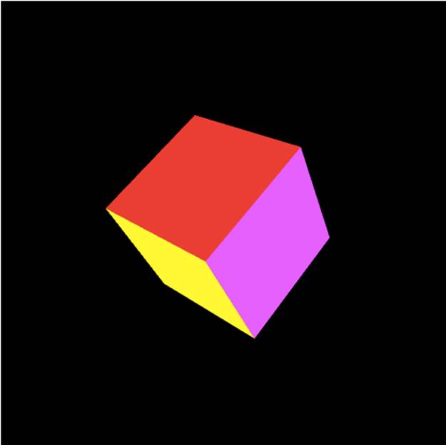
Figure 2-2. A multicolored cube
To create and render the cube, we need to adapt the previous example in a few places. First, we must change the code that creates the buffers to create cube geometry instead of square geometry. We also need to change the drawing code to use a different WebGL drawing method. The Chapter 2/example2-2.html file contains the code.
Example 2-7 shows the buffer setup for our cube. It is a bit more involved than the code to draw a square, not only because there are more vertices, but because we also want to supply different colors for each face of the cube. We first create the vertex buffer data and store it our variablevertexBuffer.
Example 2-7. Code to set up cube geometry, color, and index buffers
// Create the vertex, color, and index data for a multicolored cube
function createCube(gl) {
// Vertex Data
var vertexBuffer;
vertexBuffer = gl.createBuffer();
gl.bindBuffer(gl.ARRAY_BUFFER, vertexBuffer);
var verts = [
// Front face
−1.0, −1.0, 1.0,
1.0, −1.0, 1.0,
1.0, 1.0, 1.0,
−1.0, 1.0, 1.0,
// Back face
−1.0, −1.0, −1.0,
−1.0, 1.0, −1.0,
1.0, 1.0, −1.0,
1.0, −1.0, −1.0,
// Top face
−1.0, 1.0, −1.0,
−1.0, 1.0, 1.0,
1.0, 1.0, 1.0,
1.0, 1.0, −1.0,
// Bottom face
−1.0, −1.0, −1.0,
1.0, −1.0, −1.0,
1.0, −1.0, 1.0,
−1.0, −1.0, 1.0,
// Right face
1.0, −1.0, −1.0,
1.0, 1.0, −1.0,
1.0, 1.0, 1.0,
1.0, −1.0, 1.0,
// Left face
−1.0, −1.0, −1.0,
−1.0, −1.0, 1.0,
−1.0, 1.0, 1.0,
−1.0, 1.0, −1.0
];
gl.bufferData(gl.ARRAY_BUFFER, new Float32Array(verts), gl.STATIC_DRAW);
Next, we create color data, one four-element color per vertex, and store it in colorBuffer. The color values stored in the array faceColors are four-component RGBA.
// Color data
var colorBuffer = gl.createBuffer();
gl.bindBuffer(gl.ARRAY_BUFFER, colorBuffer);
var faceColors = [
[1.0, 0.0, 0.0, 1.0], // Front face
[0.0, 1.0, 0.0, 1.0], // Back face
[0.0, 0.0, 1.0, 1.0], // Top face
[1.0, 1.0, 0.0, 1.0], // Bottom face
[1.0, 0.0, 1.0, 1.0], // Right face
[0.0, 1.0, 1.0, 1.0] // Left face
];
var vertexColors = [];
for (var i in faceColors) {
var color = faceColors[i];
for (var j=0; j < 4; j++) {
vertexColors = vertexColors.concat(color);
}
}
gl.bufferData(gl.ARRAY_BUFFER, new Float32Array(vertexColors),
gl.STATIC_DRAW);
Finally, we create a new kind of buffer, called an index buffer, to hold a set of indices into the vertex buffer data. We store this in the variable cubeIndexBuffer. We do this because the drawing primitive we will use in our updated draw() function requires indices into the set of vertices, instead of the vertices themselves, in order to define the triangles. Why? Because 3D geometry often represents contiguous, closed regions where vertex positions are shared among multiple triangles; indexed buffers allow the data to be stored more compactly by avoiding repetition of data.
// Index data (defines the triangles to be drawn)
var cubeIndexBuffer = gl.createBuffer();
gl.bindBuffer(gl.ELEMENT_ARRAY_BUFFER, cubeIndexBuffer);
var cubeIndices = [
0, 1, 2, 0, 2, 3, // Front face
4, 5, 6, 4, 6, 7, // Back face
8, 9, 10, 8, 10, 11, // Top face
12, 13, 14, 12, 14, 15, // Bottom face
16, 17, 18, 16, 18, 19, // Right face
20, 21, 22, 20, 22, 23 // Left face
];
gl.bufferData(gl.ELEMENT_ARRAY_BUFFER, new Uint16Array(cubeIndices),
gl.STATIC_DRAW);
var cube = {buffer:vertexBuffer, colorBuffer:colorBuffer,
indices:cubeIndexBuffer,
vertSize:3, nVerts:24, colorSize:4, nColors: 24, nIndices:36,
primtype:gl.TRIANGLES};
return cube;
}
In order for the cube colors to be drawn, they must be passed to the shader. Example 2-8 shows the updated shader code. Note the lines in boldface: we declare a new vertex attribute to represent the color. We also need to declare a GLSL varying variable, vColor, which is used to pass per-vertex color information from the vertex shader to the fragment shader. Unlike uniform types such as the matrices discussed earlier, which do not change values from vertex to vertex, varying types represent information for which the shader can output a different value for each vertex. In this case, we are going to pull the color input from the color buffer data stored in memory in the vertexColor attribute. The fragment shader uses vColor unchanged to output the final pixel color value.
Example 2-8. Shader code to render the cube with colors
var vertexShaderSource =
" attribute vec3 vertexPos;\n" +
" attribute vec4 vertexColor;\n" +
" uniform mat4 modelViewMatrix;\n" +
" uniform mat4 projectionMatrix;\n" +
" varying vec4 vColor;\n" +
" void main(void) {\n" +
" // Return the transformed and projected vertex value\n" +
" gl_Position = projectionMatrix * modelViewMatrix * \n" +
" vec4(vertexPos, 1.0);\n" +
" // Output the vertexColor in vColor\n" +
" vColor = vertexColor;\n" +
" }\n";
var fragmentShaderSource =
" precision mediump float;\n" +
" varying vec4 vColor;\n" +
" void main(void) {\n" +
" // Return the pixel color: always output white\n" +
" gl_FragColor = vColor;\n" +
"}\n";
NOTE
This code may seem a bit complicated just to set a single color value. But a less trivial shader—such as one that implements a lighting model, or a shader that animates a procedural texture for grass, water, or other effects—would perform many additional calculations on vColor before outputting the final color. There’s no doubt that shaders provide a lot of visual power, but with that great power comes—as Ben Parker famously observed—great responsibility.
Now for the drawing code, shown in Example 2-9. We have to do a few things differently for the more complex cube geometry. The lines in boldface show the changes. First, we make sure WebGL knows we are drawing depth-sorted 3D objects, by enabling depth testing. If we don’t do this, there is no guarantee that WebGL will draw the faces we consider to be “in front” of other faces in such a way that they obscure the faces “in back.” (To see what happens without depth testing enabled, comment out that line and have a look. You will still see some of the cube’s faces, but not all of them.)
Next, we have to bind the color and index buffers created previously in the createCube() function. Finally, we use the WebGL method gl.drawElements() instead of gl.drawArray(). gl.drawElements() draws a set of primitives using indexed buffer information.
Example 2-9. Revised cube-drawing code
function draw(gl, obj) {
// clear the background (with black)
gl.clearColor(0.0, 0.0, 0.0, 1.0);
gl.enable(gl.DEPTH_TEST);
gl.clear(gl.COLOR_BUFFER_BIT | gl.DEPTH_BUFFER_BIT);
// set the shader to use
gl.useProgram(shaderProgram);
// connect up the shader parameters: vertex position,
// color, and projection/model matrices
// set up the buffers
gl.bindBuffer(gl.ARRAY_BUFFER, obj.buffer);
gl.vertexAttribPointer(shaderVertexPositionAttribute,
obj.vertSize, gl.FLOAT, false, 0, 0);
gl.bindBuffer(gl.ARRAY_BUFFER, obj.colorBuffer);
gl.vertexAttribPointer(shaderVertexColorAttribute,
obj.colorSize, gl.FLOAT, false, 0, 0);
gl.bindBuffer(gl.ELEMENT_ARRAY_BUFFER, obj.indices);
gl.uniformMatrix4fv(shaderProjectionMatrixUniform, false,
projectionMatrix);
gl.uniformMatrix4fv(shaderModelViewMatrixUniform, false,
modelViewMatrix);
// draw the object
gl.drawElements(obj.primtype, obj.nIndices, gl.UNSIGNED_SHORT, 0);
}
Adding Animation
If we want to see the cube as a 3D object instead of a static 2D drawing, we need to animate it. For now we will use a very simple animation technique to tumble the cube around one axis. The animation code is shown in Example 2-10. The function animate() rotates the cube around the previously defined rotationAxis over a period of five seconds.
animate() is called repeatedly by another function, run(), which drives continuous animation of the 3D scene using a new browser function called requestAnimationFrame(). This function asks the browser to call a callback function when it is time to redraw the contents of the page. (We will explore requestAnimationFrame() and various animation techniques in detail in later chapters.) Each time animate() is called, it stores the difference between the current time and the previous time it was called into the variable deltat, and uses that to derive an angle for rotating modelViewMatrix. The result is a full rotation around rotationAxis every five seconds.
Example 2-10. Animating the cube
var duration = 5000; // ms
var currentTime = Date.now();
function animate() {
var now = Date.now();
var deltat = now - currentTime;
currentTime = now;
var fract = deltat / duration;
var angle = Math.PI * 2 * fract;
mat4.rotate(modelViewMatrix, modelViewMatrix, angle, rotationAxis);
}
function run(gl, cube) {
requestAnimationFrame(function() { run(gl, cube); });
draw(gl, cube);
animate();
}
Using Texture Maps
The final WebGL API feature to explore in this chapter is texture mapping. Texture maps, or simply textures, are bitmap images displayed across the surface of geometry. You create image data for textures using the Image DOM element, which means that you can supply standard web imageformats, such as JPEG and PNG, to WebGL as textures by simply setting the Image element’s src property.
NOTE
WebGL textures don’t need to be created from image files. You can also create them using 2D Canvas elements, allowing us to draw on the surface of an object using the 2D Canvas drawing API; they can even be created from Video elements, enabling video playback on the surface of an object. These dynamic texturing capabilities will be explored in Chapter 11.
We have adapted the previous rotating cube example to use a texture map instead of face colors. The texture-mapped cube is depicted in Figure 2-3.
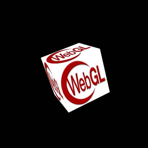
Figure 2-3. A texture-mapped cube
NOTE
I want to clarify one thing about this sample, in case you have been running it by opening the HTML file from your operating system’s file explorer. This one needs to be loaded from a web server, because we are loading a texture map from a JPEG file, which, because of cross-origin security restrictions in WebGL’s security model, requires web server operation rather than access via file:// URLs. In general, most of the examples in this book must be loaded from a web server.
I run a local version of a standard LAMP stack on my MacBook, but all you really need is the A part of LAMP—that is, a web server such as Apache. Or if you have Python installed, another option is the SimpleHTTPServer module, which you can run by going to the root of the examples directory and typing:
python -m SimpleHTTPServer
and then pointing your web browser at http://localhost:8000/. There is a great tech tip on this feature at the Linux Journal website.
The full code for this example is in the file Chapter 2/example2-3.html. Example 2-11 shows the code for loading the texture. First, we call gl.createTexture() to create a new WebGL texture object. Then we set the image property of the texture to a newly created Image object. Finally, we set the src property of the image to load a JPEG file—in this case, a 256-pixel square version of the official WebGL logo—but first we register an event handler for the image’s onload event. We do that because we will need to do a few more things with the WebGL texture object once the image is loaded.
Example 2-11. Creating a texture map from an image
var okToRun = false;
function handleTextureLoaded(gl, texture) {
gl.bindTexture(gl.TEXTURE_2D, texture);
gl.pixelStorei(gl.UNPACK_FLIP_Y_WEBGL, true);
gl.texImage2D(gl.TEXTURE_2D, 0, gl.RGBA, gl.RGBA, gl.UNSIGNED_BYTE,
texture.image);
gl.texParameteri(gl.TEXTURE_2D, gl.TEXTURE_MAG_FILTER, gl.NEAREST);
gl.texParameteri(gl.TEXTURE_2D, gl.TEXTURE_MIN_FILTER, gl.NEAREST);
gl.bindTexture(gl.TEXTURE_2D, null);
okToRun = true;
}
var webGLTexture;
function initTexture(gl) {
webGLTexture = gl.createTexture();
webGLTexture.image = new Image();
webGLTexture.image.onload = function () {
handleTextureLoaded(gl, webGLTexture)
}
webGLTexture.image.src = "../images/webgl-logo-256.jpg";
}
In the callback, handleTextureLoaded(), we do several things. First, we tell WebGL which texture we are going to use for subsequent texture API calls, by calling gl.bindTexture(). All texture-related API calls will operate on this particular texture until we callgl.bindTexture()again—which we do, at the end of the function, setting it to null so that we don’t accidentally change bits in the texture later on.
Next, we call gl.pixelStorei() to flip the y values of all of the pixels in the texture, because in WebGL, texture coordinates increase as y goes up the screen, whereas web image formats natively store pixel y values going downward.
NOTE
The i in gl.pixelStorei() stands for integer. WebGL method names follow OpenGL naming conventions, which often include a letter suffix denoting the data type of the function’s parameters. Image data is stored as an array of integer values (RGB or RGBA colors)—hence the i.
Now we are ready to copy the bits from the loaded image into the WebGL texture object. The texImage2D() method does this for us. This method’s signature comes in a few variants; consult the WebGL specification for the different ways it can be used to create textures. In this case, we specify that we are creating a 2D texture at level zero—multiple levels can be created for a texture, for use with a technique known as mip-mapping, which we will cover later in the book—with an RGBA color format, and the source data as an array of unsigned bytes.
We also must set certain texture filter options, which are parameters that govern how WebGL computes the pixel colors in a texture map as the texture scales up or down in size when the image gets closer or farther away. In our example, we use the simplest and easiest-to-compute filtering option, gl.NEAREST, which essentially tells WebGL to compute the pixel color based on scaling the original image up or down. With this option, textures look fine as long as they are not scaled up or down too much, but look blocky and pixelated when too close (scaled up) and jaggy andaliased when too far away (scaled down). WebGL provides two other texture filtering possibilities: gl.LINEAR, which linearly interpolates pixels to provide a smoother look for textures that scale up, and gl.LINEAR_MIPMAP_NEAREST, which adds mip-map filtering for smoothing out far away textures.
To see the shortcomings of gl.NEAREST filtering, try playing with the location of the cube. Edit line 47 of the source file Chapter 2/example2-3.html, changing the z coordinate of the cube’s position, −8, to make the cube appear either closer or farther away.
mat4.translate(modelViewMatrix, modelViewMatrix, [0, 0, −8]);
Try substituting −4 for −8. When the cube is closer, you can see how pixelated the texture becomes (Figure 2-4).

Figure 2-4. gl.NEAREST filtering: textures are pixelated in close-up objects
Now, try substituting −32 for −8. When the cube is farther away, you can see how jaggy (aliased) the pixels become on the texture (Figure 2-5).
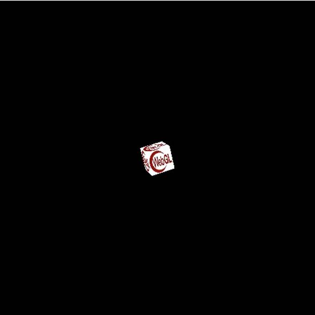
Figure 2-5. gl.NEAREST filtering: textures are aliased in faraway objects
Now that we have set our texture options, we null out the current texture using gl.bindTexture(). Finally, we set our okToRun global to true, which will tell the run() function that we now have a valid texture and therefore it is OK to call the drawing code.
As usual, we also have to adapt a few other sections of the code: the buffer creation, the shader, and the part of the drawing code that populates the shader values. First, we replace the code that created a buffer of color information with code that creates a buffer of texture coordinates. Texture coordinates are floating-point pairs defined at each vertex, with values typical ranging from 0 to 1. These values represent x, y offsets into the bitmap image data; the shader will use these values to get pixel information from the bitmap, as we will see in the shader code momentarily. Texture coordinate values for our cube are pretty easy: each face uses the entire texture, so the values for any corner of the cube face are at a corner of the texture—for example, [0, 0], [0, 1], [1, 0], or [1, 1]. Note that the order of these values must correspond to the order of the vertices in the vertex buffer. Example 2-12 shows the code to create the texture coordinate buffer.
Example 2-12. Buffer creation code for texture-mapped cube
var texCoordBuffer = gl.createBuffer();
gl.bindBuffer(gl.ARRAY_BUFFER, texCoordBuffer);
var textureCoords = [
// Front face
0.0, 0.0,
1.0, 0.0,
1.0, 1.0,
0.0, 1.0,
// Back face
1.0, 0.0,
1.0, 1.0,
0.0, 1.0,
0.0, 0.0,
// Top face
0.0, 1.0,
0.0, 0.0,
1.0, 0.0,
1.0, 1.0,
// Bottom face
1.0, 1.0,
0.0, 1.0,
0.0, 0.0,
1.0, 0.0,
// Right face
1.0, 0.0,
1.0, 1.0,
0.0, 1.0,
0.0, 0.0,
// Left face
0.0, 0.0,
1.0, 0.0,
1.0, 1.0,
0.0, 1.0,
];
gl.bufferData(gl.ARRAY_BUFFER, new Float32Array(textureCoords),
gl.STATIC_DRAW);
We must modify the shader code to use texture information instead of colors. The vertex shader defines a texCoord vertex attribute that is passed with the vertex data, and a varying output, vTexCoord, which will be sent to the fragment shader for each vertex. The fragment shader then uses this texture coordinate as an index into the texture map data, which is passed as a uniform to the fragment shader in the variable uSampler. We retrieve the pixel data from the texture using a GLSL function called texture2D(), which takes a sampler and a 2D vector x, y position. The updated shader code is shown in Example 2-13.
Example 2-13. Shader code for texture-mapped cube
var vertexShaderSource =
" attribute vec3 vertexPos;\n" +
" attribute vec2 texCoord;\n" +
" uniform mat4 modelViewMatrix;\n" +
" uniform mat4 projectionMatrix;\n" +
" varying vec2 vTexCoord;\n" +
" void main(void) {\n" +
" // Return the transformed and projected vertex value\n" +
" gl_Position = projectionMatrix * modelViewMatrix * \n" +
" vec4(vertexPos, 1.0);\n" +
" // Output the texture coordinate in vTexCoord\n" +
" vTexCoord = texCoord;\n" +
" }\n";
var fragmentShaderSource =
" precision mediump float;\n" +
" varying vec2 vTexCoord;\n" +
" uniform sampler2D uSampler;\n" +
" void main(void) {\n" +
" // Return the pixel color: always output white\n" +
" gl_FragColor = texture2D(uSampler, vec2(vTexCoord.s, vTexCoord.t));\n" +
"}\n";
As our final step in getting textures onto our cube, we have to modify the drawing function a little. Example 2-14 shows the modified code. We replace the color buffer setup code with code that sets up the texture coordinate buffer. We also set the texture to be used and connect it to the shader inputs. (As with shaders and other state in the WebGL API, there is a notion of the current, or active, texture.) At long last, our cube is ready to draw with gl.drawElements().
Example 2-14. Setting up texture map data for drawing
gl.vertexAttribPointer(shaderTexCoordAttribute, obj.texCoordSize, gl.FLOAT,
false, 0, 0);
gl.bindBuffer(gl.ELEMENT_ARRAY_BUFFER, obj.indices);
gl.uniformMatrix4fv(shaderProjectionMatrixUniform, false, projectionMatrix);
gl.uniformMatrix4fv(shaderModelViewMatrixUniform, false, modelViewMatrix);
gl.activeTexture(gl.TEXTURE0);
gl.bindTexture(gl.TEXTURE_2D, webGLTexture);
gl.uniform1i(shaderSamplerUniform, 0);
Chapter Summary
This chapter showed us how to use the WebGL API to render graphics. We went through the basics of setting up a WebGL application, including creating a context, viewports, buffers, matrices, shaders, and drawing primitives. We explored how to create 2D and 3D geometry and paint it with colors and bitmap textures. We even got a little help from the open source libraries glMatrix and RequestAnimationFrame.js, two staples of WebGL development.
It should be apparent by now that WebGL programming, at its lowest level, is a lot of work. We were able to get somewhat complex geometry with colors and textures moving around on the page; however, it took hundreds of lines of code. There is huge power in there—you can do practically anything you can imagine to every vertex and pixel on the screen, at blinding, hardware-accelerated speeds. But it requires heavy lifting. The designers of the standard made a conscious decision to trade size for power. The API is small and simple, at the cost of requiring a lot of coding on the application side.
If you’re an experienced game or graphics programmer and you want to have fine control over the performance and feature set of your application, working directly with the WebGL API might be right for you. If you are building an application with very specific rendering requirements—say, an image-processing application or 3D modeling tool—staying close to the WebGL metal is probably your best option. You will still probably want to build some abstractions on top—nobody wants to write the same 40 lines of code over and over again to create a cube, for example—but that layer will be all your own and you will know and control every line of code.
However, if you are a mere mortal like most of us, you will want to work at a higher level than WebGL, hopefully by using tools that have already been developed. The good news is that several already exist: there are some great open source libraries built on top of WebGL. We will be exploring them in the next several chapters. Let’s get to it.
[1] As of this writing, the sole holdout in supporting mobile WebGL is Mobile Safari on iOS. This is kind of a big deal; thankfully, there are adapter toolkits that allow us to create HTML5 and WebGL-based iOS native applications to work around the issue. This topic is covered in detail in Chapter 12.
All materials on the site are licensed Creative Commons Attribution-Sharealike 3.0 Unported CC BY-SA 3.0 & GNU Free Documentation License (GFDL)
If you are the copyright holder of any material contained on our site and intend to remove it, please contact our site administrator for approval.
© 2016-2026 All site design rights belong to S.Y.A.