A practical guide to Fedora and Red Hat Enterprise Linux, 7th Edition (2014)
Part II: Using Fedora and Red Hat Enterprise Linux
Chapter 8. Networking and the Internet
In This Chapter
Types of Networks and How They Work
Network Protocols
IPv6
Network Utilities
ping: Tests a Network Connection
traceroute: Traces a Route over the Internet
host and dig: Query Internet Nameservers
whois: Looks Up Information About an Internet Site
Distributed Computing
WWW: World Wide Web
Objectives
After reading this chapter you should be able to:
![]() Discuss a variety of network types
Discuss a variety of network types
![]() Define several network protocols
Define several network protocols
![]() List the software and hardware components of networks
List the software and hardware components of networks
![]() Explain the features and advantages of IPv6
Explain the features and advantages of IPv6
![]() List several network utilities
List several network utilities
![]() Explain how ping works
Explain how ping works
![]() Use dig to determine the nameserver for a Web site
Use dig to determine the nameserver for a Web site
![]() Describe distributed computing
Describe distributed computing
![]() Explain the role of the World Wide Web
Explain the role of the World Wide Web
![]() Introduction to Networking
Introduction to Networking
The communications facilities linking computers are continually improving, allowing faster and more economical connections. The earliest computers were unconnected stand-alone systems. To transfer information from one system to another, you had to store it in some form (usually magnetic tape, paper tape, or punch cards—called IBM or Hollerith cards), carry it to a compatible system, and read it back in. A notable advance occurred when computers began to exchange data over serial lines, although the transfer rate was slow (hundreds of bits per second). People quickly invented new ways to take advantage of this computing power, such as email, news retrieval, and bulletin board services. With the speed and ubiquity of today's networks, a piece of email can cross the country or even travel halfway around the world in a fraction of a second.
Today it would be difficult to find a computer facility that does not include a LAN to link its systems. Linux systems are typically attached to an Ethernet (page 1249) network. Wireless networks are also prevalent. Large computer facilities usually maintain several networks, often of different types, and almost certainly have connections to larger networks (companywide or campuswide and beyond).
![]() Internet
Internet
The Internet is a loosely administered network of networks (an internetwork) that links computers on diverse LANs around the globe. An internet (small i) is a generic network of networks that might share some parts in common with the public Internet. It is the Internet that makes it possible to send an email message to a colleague thousands of miles away and receive a reply within minutes. A related term, intranet, refers to the networking infrastructure within a company or other institution. Intranets are usually private; access to them from external networks might be limited and carefully controlled, typically using firewalls (page 288).
Network services
Over the past decade many network services have emerged and become standardized. On Linux and UNIX systems, special processes called daemons (page 1245) support such services by exchanging specialized messages with other systems over the network. Several software systems have been created to allow computers to share filesystems with one another, making it appear as though remote files are stored on local disks. Sharing remote filesystems allows users to share information without knowing where the files physically reside, without making unnecessary copies, and without learning a new set of utilities to manipulate them. Because the files appear to be stored locally, you can use standard utilities (e.g., cat, vim, lpr, mv, or their graphical counterparts) to work with them.
Many tools take advantage of networks for more than sharing files. These tools have varied tasks, from executing programs remotely to communicating between computers, programs, and people. The ssh (secure shell, page 685) utility is the standard tool for remote command execution and remote computer access. Years ago it replaced insecure tools such as rsh, telnet, and rlogin. The ssh utility encompasses the features of these tools and includes builtin security features for safe and private access across public networks. Some devices do not implement ssh, but not many.
Previously, users communicated using command-line tools such as talk, write, and IRC (Internet Relay Chat). These tools are still around, particularly IRC, but their use has waned in preference to Facebook, Twitter, Google Talk, Skype, and older IM (Instant Messaging) tools like MSN, AIM, ICQ, and Yahoo Messenger. Many people use the Empathy IM client for Linux. Jabber is popular in private company networks.
Intranet
An intranet is a network that connects computing resources at a school, company, or other organization but, unlike the Internet, typically restricts access to internal users. An intranet is usually composed of one or more local area networks (LANs) but could be fairly large for a regional, national, or worldwide company. An intranet can provide database, email, and Web page access to a limited group of people, regardless of their geographic location.
The ability of an intranet to connect dissimilar machines is one of its strengths. Think of all the machines you can find on the Internet: Macintosh systems, PCs running different versions of Windows, machines running UNIX and Linux, and so on. Each of these machines can communicate via the IP protocol suite (page 290). The intranet defines the communication boundaries and security trust zones that enable this communication.
Another key difference between the Internet and an intranet is that the Internet transmits only one protocol suite natively: IP. In contrast, an intranet can be set up to use a number of protocols, such as IP, AppleTalk, or other protocols developed by vendors over the years. Although these protocols cannot be transmitted directly over the Internet, you can set up gateway boxes at remote sites that tunnel or encapsulate these protocols into IP packets and then use the Internet to pass them. In practice, most of the older protocols have been rewritten to use IP as a transport. Even storage protocols and networks like SCSI and Fibre Channel have IP implementations now (iSCSI, FCoE).
You can use an extranet (also called a partner net) or a VPN (virtual private network) to improve security. These terms describe ways to connect remote sites securely to a local site, typically by using the public Internet as a carrier and employing encryption as a means of protecting data in transit. A typical use of an extranet is to link research institutions for collaboration or to link a parts supplier and a manufacturer to obtain direct inventory access.
Following are some terms you might want to become familiar with before you read the rest of this chapter:
ASP (page 1237)
bridge (page 1240)
extranet (page 1249)
firewall (page 1250)
gateway (page 1251)
hub (page 1254)
internet (page 1255)
Internet (page 1255)
intranet (page 1255)
ISP (page 1256)
packet (page 1265)
router (page 1271)
sneakernet (page 1273)
switch (page 1276)
VPN (page 1280)
Types of Networks and How They Work
Computers communicate over IP networks using unique addresses assigned by system software. An IP packet includes the address of the destination computer and the sender’s return address. Networks can consist of many distinct topologies, or arrangements of computers and networking equipment. The most common topologies are broadcast, point-to-point, and switched. Ethernet is the most common topology used in LANs (local area networks, discussed shortly). Ethernet speeds range from 10 megabits per second to 100 gigabits per second (not formally accepted as of this writing). Other types of LANs include Myrinet, Infiniband, and Quadrics, but they are used mostly in high-performance computing.
Speed is critical to the proper functioning of the Internet. Newer specifications (cat 6 and cat 7) are being adopted for 10000BaseT (10 gigabits per second; also called 10GE) and faster networking. Specialized cables are required for higher speeds. SFP+ and QSFP are in common use. Many of the networks that form the backbone of the Internet run at speeds of 38 gigabits per second (OC768) to accommodate the ever-increasing demand for network services. Table 8-1 lists some of the specifications in use today.
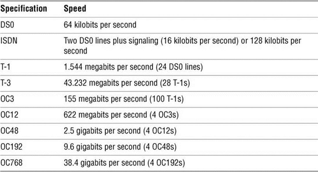
Table 8-1 Network specifications
Broadcast Networks
On a broadcast network, any of the many systems attached to the network cable can send a message at any time; each system examines the destination address in each message and responds only to messages addressed to it. A problem occurs on a broadcast network when multiple systems send data at the same time, resulting in a collision of the messages on the cable. When messages collide, they can become garbled. The sending system notices the garbled message and resends it after waiting a short but random amount of time. Waiting a random amount of time helps prevent those same systems from resending the data at the same moment and experiencing yet another collision. The extra traffic that results from collisions can strain the network; if the collision rate gets too high, retransmissions might result in more collisions. Ultimately the network might become unusable.
A special broadcast (page 1240) packet in a network requires all machines to inspect the packet. Certain protocols take advantage of this feature: The ARP protocol, which is used for IP addresses to MAC (Ethernet) addresses resolution, the PXE network boot protocol, DHCP, and some service discovery protocols all use broadcast packets.
Point-to-Point Networks
A point-to-point link does not seem like much of a network because only two endpoints are involved. However, most connections to WANs (wide area networks) go through point-to-point links, using wire cable, radio, or satellite links. The advantage of a point-to-point link is its simplicity: Because only two systems are involved, the traffic on the link is limited and well understood. A disadvantage is that each system can typically be equipped for only a small number of such links; it is impractical and costly to establish point-to-point links that connect each computer to all the rest. For example two hosts require one link, three hosts require three links, four hosts require six links, and five hosts require ten links to connect a point-to-point network. The number of required links increases more quickly as you add more hosts. Point-to-point links often use serial links and specialized interfaces.
The most common types of point-to-point links are the ones used to connect to the Internet. When you use DSL1 (digital subscriber line), you are using a point-to-point link to connect to the Internet. Serial lines, such as T-1, T-3, ATM links, FIOS, and ISDN, are all point-to-point. Although it might seem like a point-to-point link, a cable modem is based on broadcast technology and in that way is similar to Ethernet.
1. The term DSL incorporates the xDSL suite of technologies, which includes ADSL, IDSL, HDSL, SDSL, and XDSL.
Switched Networks
With the introduction of switched networks, pure broadcast networks became a thing of the past. A switched network runs in full duplex mode, allowing machines and network equipment to send and receive data at the same time. Support for full duplex is built-in and required in gigabit networks and above, on 100-megabit networks it is optional, and on 10-megabit networks it is rare.
A switch is a device that establishes a virtual path between source and destination hosts in such a way that each path appears to be a point-to-point link, much like an old-fashioned telephone switchboard. Instead of the operator using a plug to connect your local line to an outgoing line, the switch inspects each packet to determine its destination and directs the packet appropriately.
The switch creates and tears down virtual paths as hosts seek to communicate with each other. Each host thinks it has a direct point-to-point path to the host it is talking to. Contrast this approach with a broadcast network, where each host also sees traffic bound for other hosts. The advantage of a switched network over a pure point-to-point network is that each host requires only one connection: the connection to the switch. Using pure point-to-point connections, each host must have a connection to every other host. Scalability is provided by further linking switches.
To achieve this reduction in traffic, Ethernet switches learn which hosts are on which ports. When traffic comes in destined for a host, the switch looks up which port that host is connected to in its CAM2 and sends the packet out that port. When a switch has not yet heard from a host matching the destination, or if the packet is a special broadcast packet, the packet is flooded out on all ports just like a packet in a broadcast network. A switched Ethernet network is a technological enhancement over a broadcast network.
2. A memory table used to dereference (page 1246) Ethernet addresses.
LAN: Local Area Network
Local area networks (LANs) are confined to a relatively small area—a single computer facility, building, or campus. Today most LANs run over copper. Fiberoptic (glass or plastic) cable, wireless (Wi-Fi), and sometimes infrared (similar to most television remote control devices) are also common infrastructure.
If its destination address is not on the local network, a packet must be passed on to another network by a router (page 287). A router might be a general-purpose computer or a special-purpose device attached to multiple networks to act as a gateway among them.
Switching terminology
You might see references to a layer-2 switch, layer-3 switch, or layer-4 switch. These terms refer to the IP networking model (page 290). A layer-2 switch is what the preceding discussion of switched networks describes. A layer-3 switch is equivalent to a router; it combines features of layer-2 switching and routing. A single layer-3 switch can connect multiple independent LANs. Layer-4 switches inspect higher-level packets to make decisions. Most Web load balancers are layer-4 switches. They can route traffic to many devices to spread the load on the network.
Ethernet
A Linux system connected to a LAN usually connects to a network using Ethernet. A typical Ethernet connection can support data transfer rates from 10 megabits per second to 100 gigabits per second. Transfer rates of 10 megabits per second, 100 megabits per second, and 1 gigabit per second use the same, older technology. However, 10, 40, and 100 gigabit per second transfer rates require newer technology and specialized cables. Ten gigabit per second Ethernet can be compatible with 1 gigabit per second Ethernet by using physical media adapters. Because of the need for extremely tight tolerances, 40 and 100 gigabit per second Ethernet are not backward compatible. The technology required for these higher-speed transfer rates requires very precisely defined physical interfaces. The hardware is quite expensive and common only in the network infrastructure realm and HPC (high performance computing) environments, connecting multiple switches using high-speed links.
Cables
As mentioned earlier, a modern Ethernet network transfers data using copper or fiberoptic cable or wireless transmitters and receivers. Originally, each computer was attached to a thick coaxial cable (called thicknet) at tap points spaced at six-foot intervals along the cable. The thick cable was awkward to deal with, so other solutions, including a thinner coaxial cable called thinnet, or 10Base2,3 were developed.
3. Versions of Ethernet are classified as XBaseY, where X is the data rate in megabits per second, Base means baseband (as opposed to radio frequency), and Y is the category of cabling.
Today most Ethernet connections are either wireless or made over UTP (unshielded twisted pair). There are a number of UTP standards, each referred to by a category and a number. Some examples are Category 5 [cat 5], Category 5e [cat 5e], and Category 6 [cat 6]. These categories specify how far the cable can carry a signal. The higher the number, the tighter the tolerances and the more expensive the cable, but the farther it can reliably carry a signal. These standards specify the physical connectors at the ends of the cables, how tightly the wires in the cable are twisted, and various other parameters. The terms 10BaseT, 100BaseT, and 1000BaseT refer to Ethernet over cat-3/4/5/5e/6/7 cables. STP (shielded twisted pair) is not very common.
Segment
A network segment is a part of a network in which all systems communicate using the same physical layer (layer 1) of the IP and OSI models (page 291). It is of arbitrary size and can be a part of a WAN, MAN, or another network.
Duplex
In half-duplex mode, packets travel in one direction at a time over the cable. In full-duplex mode, packets travel in both directions.
Hub
A hub (sometimes called a concentrator) is a device that connects systems so they are all part of one network segment and share the network bandwidth. Hubs work at the physical layer of the IP and OSI models (layer 1, page 291). All packets are sent to all hosts (flooded). For the most part, hubs have been replaced by switches.
Switch
A switch connects network segments. A switch inspects each data packet; it learns which devices are connected to which of its ports. The switch sends each packet only to the device it is intended for. Because a switch sends packets only to their destination devices, it can conserve network bandwidth and perform better than a hub. Some switches have buffers that hold and queue packets.
Switches work at layers 2 and higher of the IP and OSI models (page 290). A layer-2 switch works at the data link layer, and a layer-3 switch works at the IP layer and routes packets. Layer-4 switches work at the transport and application layers and are the basis for load balancers and application proxies.
All modern Ethernet switches have enough bandwidth to communicate simultaneously, in full-duplex mode, with all connected devices. A nonswitched (hub-based) broadcast network can run in only half-duplex mode. Full-duplex Ethernet further improves efficiency by eliminating collisions. Each host on a full-duplex switched network can transmit and receive simultaneously at the speed of the network (e.g., 100 megabits per second) for an effective bandwidth between hosts of twice the speed of the network (e.g., 200 megabits per second), depending on the capacity of the switch.
Bridge
A network bridge connects multiple network segments at the data link layer (IP layer 2) of the OSI model. A bridge is similar to a repeater or network hub, devices that connect network segments at the physical layer; however, a bridge works by forwarding traffic from one network segment to another only if the destination device specified in the packet is known to be on the remote segment. A bridge does not forward traffic between LAN hosts on the same side of the bridge.
In Ethernet networks, the term bridge formally means a device that behaves according to the IEEE 802.1D standard. Marketing literature frequently refers to this type of device as a network switch.
Router
A router connects networks at layer 3 of the IP and OSI models (page 291). For example, a router can connect a LAN to a WAN (such as the Internet) or it can connect two LANs. A router determines which path packets should take to travel to a different network and forwards the packets. Routers work at the network layer of the IP and OSI models (layer 3). “Internetworking Through Gateways and Routers” on the next page covers routers in more depth.
VLAN
A VLAN (virtual local area network or virtual LAN) is a logical entity defined in software. It defines a group of hosts that share the same broadcast domain (layer 2). That is, when a host sends out a broadcast packet, such as an ARP packet, it will arrive at all other hosts in the same VLAN. All modern, managed switches, those that have a command line or Web interface, have VLAN capability. A VLAN allows an administrator to group hosts into IP ranges (LANs). VLANs commonly group hosts by department, organization, or security needs. Hosts in the same VLAN communicate with each other using layer 2, and hosts in different VLANs communicate using layer 3. The primary difference between a LAN and a VLAN is that in a LAN (a nonmanaged switch), all hosts are in the same broadcast domain, whereas in a VLAN, there can be multiple broadcast domains on a single switch.
Broadcast domains and IP protocol layer 2 segments are effectively the same thing. However, layer 2 can be confused with hosts (network addresses) being in the same IP network. Consider the classic concentrator, a device that sends out all packets on all ports all the time. These ports might include separate networks. For example, some hosts might be in network 10.0.1.0, and others might be in network 192.168.1.0. Ethernet broadcast packets do not know the difference between the networks; these packets go to all hosts regardless of IP address. This setup is sometimes referred to as a collision domain. VLANs enable you to place the hosts in the IP network 10.0.1.0 into one VLAN and the hosts in 192.168.1.0 into another, so the networks do not share each other’s broadcasts. VLANs also enable you to connect hosts that share the same function across a corporate network.
Wireless
Wireless networks are becoming increasingly common. They are found in offices, homes, and public places, such as universities, coffee shops, and airports. Wireless access points provide functionality similar to an Ethernet hub. They allow multiple users to interact via a common radio frequency spectrum. A wireless, point-to-point connection allows you to wander about your home or office with a laptop, using an antenna to link to a LAN or to the Internet via an in-house base station. Linux includes drivers for many wireless devices. A wireless access point, or base station, connects a wireless network to a wired network so that no special protocol is required for a wireless connection. Refer to the Linux Wireless LAN HOWTO at www.hpl.hp.com/personal/Jean_Tourrilhes/Linux.
WAN: Wide Area Network
A WAN (wide area network) covers a large geographic area. In contrast, the technologies (such as Ethernet) used for LANs were designed to work over limited distances and for a certain number of host connections. A WAN might span long distances over dedicated data lines (leased from a telephone company) or radio or satellite links. Such networks are often used to connect LANs and typically support much lower bandwidth than LANs because of the expense of the connection. Major Internet service providers rely on WANs to connect to their customers within a country and around the globe.
MAN
Some networks do not fit into either the LAN or the WAN designation. A metropolitan area network (MAN) is a network that is contained in a smaller geographic area, such as a city. Like WANs, MANs are typically used to interconnect LANs.
Internetworking Through Gateways and Routers
Gateway
A LAN connects to a WAN through a gateway, a generic term for a computer or a special device with multiple network connections that passes data from one network to another. A gateway connects a LAN to other LANs, VLANs, or to a WAN. Data that crosses the country from one Ethernet to another over a WAN, for example, is repackaged from the Ethernet format to a different format that can be processed by the communications equipment that makes up the WAN backbone. When it reaches the end of its journey over the WAN, the data is converted by another gateway to a format appropriate for the receiving network. For the most part, these details are of concern only to the network administrators; the end user does not need to know anything about how the data transfer takes place.
Router
The modern, canonical reference to a gateway is to the default gateway, which is the router that connects a LAN or VLAN to other networks. Routers play an important role in internetworking. Just as you might study a map to plan your route when you need to drive to an unfamiliar place, so a computer needs to know how to deliver a message to a system attached to a distant network by passing through intermediary systems and networks along the way. Although you might envision using a giant network road map to choose the route that your data should follow, a static map of computer routes is usually a poor choice for a large network. Computers and networks along the route you choose might be overloaded or down and not provide a detour for your message.
Routers instead communicate dynamically, keeping each other informed about which routes are open for use. To extend the analogy, this situation is like heading out on a car trip without consulting a map to find a route to your destination; instead you head for a nearby gas station and ask directions. Throughout the journey you continue to stop at one gas station after another, getting directions at each to find the next one. Although it would take a while to make the stops, the owner of each gas station would advise you of bad traffic, closed roads, alternative routes, and shortcuts.
The stops made by the data are much quicker than those you would make in your car, but each message leaves each router on a path chosen based on the most current information. Think of this system as a GPS (global positioning system) setup that automatically gets updates at each intersection and tells you where to go next, based on traffic and highway conditions.
Figure 8-1 shows an example of how LANs might be set up at three sites interconnected by a WAN (the Internet). In this type of network diagram, Ethernet LANs are drawn as straight lines, with devices attached at right angles; WANs are represented as clouds, indicating the details have been left out; and wireless connections are drawn as zigzag lines with breaks, indicating the connection might be intermittent.
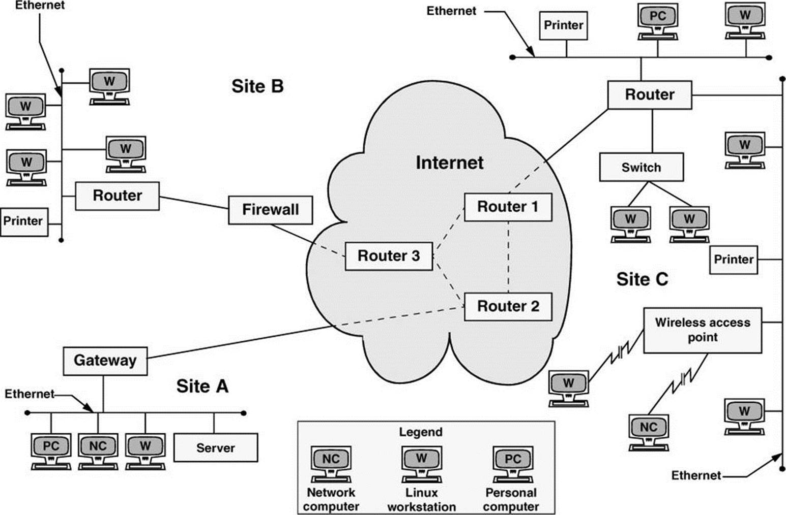
Figure 8-1 A slice of the Internet
In Figure 8-1, a gateway or a router relays messages between each LAN and the Internet. The figure shows the three routers in the Internet that are closest to each site. Site A has a server, a workstation, a network computer, and a PC sharing a single Ethernet LAN. Site B has an Ethernet LAN that serves a printer and four Linux workstations. A firewall permits only certain traffic to pass between the Internet router and the site’s local router. Site C has three LANs linked by a single router, perhaps to reduce the traffic load that would result if the LANs were combined or to keep workgroups or locations on separate networks. Site C also includes a wireless access point that enables wireless communication with nearby computers.
Firewall
A firewall in a car separates the engine compartment from the passenger compartment, protecting the driver and passengers from engine fires, noise, and fumes. In much the same way, computer firewalls separate computers from malicious and unwanted users.
A firewall prevents certain types of traffic from entering or leaving a network. For example, a firewall might prevent traffic from your IP address from leaving the network and prevent anyone except users from selected domains from using FTP to retrieve data from the network. The implementations of firewalls vary widely—from Linux machines with two interfaces (page 1255) running custom software to a router (preceding section) with simple access lists to esoteric, vendor-supplied firewall appliances. Most larger installations have at least one kind of firewall in place. A firewall is often accompanied by a proxy server/gateway (page 316) that provides an intermediate point between you and the host you are communicating with.
In addition to the firewalls found in multipurpose computers, firewalls are becoming increasingly common in consumer appliances. For example, they are built into cable modems, wireless gateways, routers, and stand-alone devices.
Typically a single Linux machine will include a minimal firewall. A small group of Linux systems might have an inexpensive Linux machine with two network interfaces and packet-filtering software functioning as a dedicated firewall. One of the interfaces connects to the Internet, modems, and other outside data sources. The other connects, normally through a hub or switch, to the local network. Refer to Chapter 25 for information on firewalld, firewall-config, iptables, and setting up a firewall and to Appendix C for a discussion of security.
![]() Network Protocols
Network Protocols
![]() TCP
TCP
To exchange information over a network, computers must communicate using a common language, or protocol (page 1267). The protocol determines the format of message packets. The predominant network protocols used by Linux systems are TCP and IP,4 collectively referred to as TCP/IP (Transmission Control Protocol and Internet Protocol). Network services that require highly reliable connections, such as ssh and scp, tend to use TCP/IP.
4. All references to IP imply IPv4 (page 1256).
![]() UDP
UDP
Network services that do not require guaranteed delivery but require timely delivery, such as video, audio, and time services, operate using the simpler UDP (User Datagram Protocol; UDP/IP). VoIP (voice over IP) and NTP (Network Time Protocol) fall into this category. UDP packets are sent and then forgotten. Voice and video protocols are delay sensitive, not integrity sensitive. The human ear and eye accept and interpolate loss in an audio or video stream but cannot deal with variable delay. The guaranteed delivery that TCP provides can introduce a delay on a busy network when packets are retransmitted. This delay is not acceptable for video and audio transmissions, whereas less than 100 percent integrity is acceptable. In the case of NTP, missing packets are acceptable, but packets that are delayed because of TCP retransmission can result in significantly skewed time settings.
IP: Internet Protocol
Layering was introduced to facilitate protocol design: Layers distinguish functional differences between adjacent protocols. A grouping of layers can be standardized into a protocol model. IP has a model that distinguishes protocol layers and that differs from the ISO seven-layer protocol model (also called the OSI model) often illustrated in networking textbooks. Specifically IP uses the following simplified five-layer model:
1. The first layer of the IP protocol, called the physical layer, describes the physical medium (e.g., copper, fiber, wireless) and the data encoding used to transmit signals on that medium (e.g., pulses of light, electrical waves, or radio waves).
2. The second layer, called the data link layer, covers media access by network devices and describes how to put data into packets, transmit the data, and check it for errors. Ethernet is found at this layer, as is 802.11 (page 1236) wireless.
3. The third layer, called the network layer, frequently uses IP and addresses and routes packets. It allows data to traverse the networks.
4. The fourth layer, called the transport layer, is where TCP and UDP exist. This layer provides a means for applications to communicate with each other. Functions commonly performed by the transport layer include guaranteed delivery, delivery of packets in the order of their transmission, flow control, error detection, and error correction. The transport layer is responsible for dividing data streams into packets. In addition, this layer performs port addressing, which allows it to distinguish among different services using the same transport protocol. Port addressing keeps the data from multiple applications using the same protocol (for example, TCP) separate.
5. Anything above the transport layer is the domain of the application and is part of the fifth layer. Unlike the ISO model, the Internet model does not distinguish among application, presentation, and session layers. All the upper-layer characteristics, such as character encoding, encryption, and GUIs, are part of the application. Applications choose the transport characteristics they require as well as the corresponding transport layer protocol with which to send and receive data.
![]() TCP: Transmission Control Protocol
TCP: Transmission Control Protocol
TCP is most frequently run on top of IP in a combination referred to as TCP/IP. This protocol provides error recovery and guaranteed delivery in packet transmission order; it also works with multiple ports so that it can handle more than one application. TCP is a connection-oriented protocol(page 1244), also known as a stream-based protocol. Once established, a TCP connection looks like a stream of data, not individual IP packets. The connection is assumed to remain up and be uniquely addressable. Every piece of information you write to the connection always goes to the same destination and arrives in the order it was sent. Because TCP is connection oriented and establishes a virtual circuit between two systems, this protocol is not suitable for one-to-many transmissions (see the discussion of UDP, following). TCP has builtin mechanisms for dealing with congestion (or flow) control over busy networks and throttles back (slows the speed of data flow) when it has to retransmit dropped packets. TCP can also deal with acknowledgments, wide area links, high-delay links, and other situations.
![]() UDP: User Datagram Protocol
UDP: User Datagram Protocol
UDP runs at layer 4 of the IP stack, just as TCP does, but is much simpler. Like TCP, UDP works with multiple ports and multiple applications. It has checksums for error detection but does not automatically retransmit datagrams (page 1246) that fail the checksum test. UDP is a datagram-oriented protocol: Each datagram must carry its own address and port information. Each router along the way examines each datagram to determine the destination, one hop at a time. You can broadcast or multicast UDP datagrams to many destinations at the same time by using special addresses.
PPP: Point-to-Point Protocol
PPP provides serial line point-to-point connections that support IP. It compresses data to make the most of the limited bandwidth available on these connections. PPP acts as a point-to-point layer 2/3 transport that many other types of protocols can ride on. Today it is used mostly in devices such as cable modems. Previously, it was used as a transport for TCP and UDP on dial-up modems that connected a computer to the Internet.
![]() IPv4
IPv4
Under IPv4, the network address of a machine is an IP address that is represented as one number broken into four octets5 separated by periods (for example, 192.168.184.5). Domain names and IP addresses are assigned through a highly distributed system coordinated by ICANN (Internet Corporation for Assigned Names and Numbers—www.icann.org) via many registrars (see www.internic.net). ICANN is funded by the various domain name registries and registrars and by IP address registries, which supply globally unique identifiers for hosts and services on the Internet. Although you might not deal with any of these agencies directly, your Internet service provider most assuredly does.
5. Using binary notation, an eight-bit byte can represent the range of 0–255, thus the term octet.
How a company uses IP addresses is determined by the system or network administrator. For example, the two leftmost sets of numbers in an IP address might represent a large network (campuswide or companywide); the third set, a subnetwork (perhaps a department or a single floor in a building); and the rightmost number, an individual computer. The operating system uses the address in a different, lower-level form, converting it to its binary equivalent, a series of 1s and 0s. Refer to “Private address space” on page 637 for information about addresses you can use on a LAN without registering them.
![]() IPv6
IPv6
Tip: Getting started with IPv6
Even if the ISP you do business with does not provide IPv6 service, it is still easy and free to participate on the IPv6 Internet by using a tunnel broker. For more information on tunnel brokers see en.wikipedia.org/wiki/List_of_IPv6_tunnel_brokers. Setting up a small home or lab network through a tunnel broker is an excellent way to gain experience with IPv6 and experiment with its configurations and capabilities. Most tunnel brokers offer instructions on how to get various platforms working with their service.
IPv6 (Internet Protocol version 6)6 is the next generation of the Internet Protocol. Since the introduction of IPv4 (Internet Protocol version 4) in 1980, the Internet has undergone explosive growth that has caused its needs to exceed the capabilities of IPv4. A proliferation of Internet connected devices, including cellular telephones, tablet computers, electronic book readers, and advanced televisions and set-top boxes, all of which need an IP address in order to communicate on the Internet, has fueled that growth. IPv4 uses a 32-bit address space, which is no longer sufficient to give a unique IP address to every device on the Internet. The lack of IPv4 address space has been mitigated by the use of NAT (page 1262) and by other techniques, but each of these techniques comes with limitations and overhead.
6. IPv5 referred to an experimental real-time stream protocol named ST—thus the jump from IPv4 to IPv6.
IPv6 uses a 128-bit address space, which ensures that all devices can have unique IP addresses without resorting to such mitigations, and provides enormous room to grow as the Internet continues to expand. While the enormous address space in IPv6 is its most compelling feature in light of the shortage of IPv4 addresses, IPv6 has many other desirable features:
• IPv6 enables stateless address autoconfiguration. With IPv4, DHCP (page 491) is usually used to automate network configuration. With IPv6, autoconfiguration makes it possible for hosts to configure their IP addresses automatically and autonomously without the need for a central service like DHCP.
• In IPv6, multicast (page 1262 and next) is mandatory and fundamental to its operation.
• IPv6 provides a simplified packet header that reduces router complexity by improving routing efficiency and cuts router cost by eliminating the need for much hardware acceleration.
• IPv6 reserves 20 bits in the header for advanced services, such as resource reservation protocols, better backbone routing, and improved traffic engineering.
IPv6 can coexist with IPv4. Even though the protocols are very similar in many ways, the network considers them to be different protocols, so one will not interfere with the other. Also, most operating systems support IPv4 and IPv6 simultaneously by using a dual-stack configuration. This configuration is likely to be common for a long time because it allows IPv6-enabled hosts to reach legacy IPv4-only hosts easily.
Multicast Packets
IPv6 does not use broadcast (page 1240) packets and therefore does not have a broadcast address (page 1240) that corresponds to the IPv4 broadcast address. IPv6 mandates the implementation and use of multicast (page 1262).
Multicast improves the efficiency of the network by reducing the amount of traffic that each host must process: The system network interface does not ordinarily pass to the host multicast traffic it is not registered to receive.
For example, when a host wants to discover a DHCPv6 server, it sends a packet to the “all DHCPv6 servers” well-known link-local multicast address (ff05::1:3). This packet is processed only by hosts running DHCPv6. Under IPv4 the host must send a broadcast packet to discover the DHCP server. This packet is processed by every host on the network.
Many tools, such as ssh, work with IPv6 and IPv4 without difficulty. Some tools have special versions that work with IPv6 (e.g., ping6, traceroute6, and ip6tables).
Addresses
Because they are much longer, IPv6 addresses are quite different from IPv4 addresses. For brevity and clarity, IPv6 addresses are usually expressed as eight sets of four hexadecimal digits, each set separated from the next by a colon. As an example, consider the IPv6 address 2001:4860:800a:0000:0000:0000:0000:0067.
To shorten the address and allow it to remain unambiguous, you can replace any number of adjacent sets of four zeros and the colons that enclose them with two colons. After making this replacement, you can represent the example address as 2001:4860:800a::0067. With this replacement, you (or a computer) can easily expand the shortened address by adding enough sets of four zeros to fill out the eight sets in the address. You cannot make this replacement more than once in an address. If you did, when you tried to expand the address you would not know how many sets of zeros to replace each double colon with.
As an additional way of shortening an address, you can eliminate any leading zeros in any set of four digits. Using this technique, you can write the example address as 2001:4860:800a::67, which is much more manageable than the original address. You can also use CIDR notation (page300): The example host might be in an allocation such as 2001:4860:800a::/48.
In IPv6, the network prefix is always 64 bits, and the host part is always the remaining 64 bits. In other words, all networks are the same size. If an organization were given the network allocation 2001:4860:800a::/48, it would have 16 bits of network address space to use, each network being of the form 2001:4860:800a:xxxx::/64, where xxxx is any one of the 65,536 possible numbers in 16 bits. Because of the immense size of the IPv6 address space, this allocation is considered small, although even very large organizations would fit well within it.
Autoconfiguration
A constant host address length of 64 bits allows for stateless address autoconfiguration. Using a multicast ICMPv6 packet, the router sends periodic advertisements to all hosts on the network, telling them of its ability to route for a given network prefix. At the same time, it gives hosts permission to assign themselves addresses using that prefix.
A host that hears this advertisement can construct a host address in a deterministic way by incorporating the hardware address of the network adapter (i.e., the MAC address [page 296]). Without resorting to the use of a stateful service (e.g., DHCP) to maintain a list of assigned addresses, this construction guarantees that no other host on the network will have the same address. After constructing a host address, the host finalizes the configuration by adding a default route to the router from which the advertisement came. Alternately, when a host interface initially comes up, it can solicit router information by sending a request to all routers instead of waiting for the periodic advertisement, speeding up the process. Once it has assigned itself an address, the host expects to hear periodic advertisements from the router. If it does not hear these advertisements, the host will eventually expire its knowledge of this autoconfigured route and address.
Link-local Addresses
A link-local IP address can be used to communicate only with other systems on the network; a router will not forward a packet that has a link-local address. This address is autoconfigured in a manner similar to that explained in the preceding section, except the network prefix is always fe80::/64, marking it as a link-local address.
This setup contrasts with how IPv4 DHCP works: Because an IPv4 host does not have an address when it initially communicates with a DHCP server, a hack is needed to use a fake address for the host. Such hacks are not necessary in IPv6 because of autoconfigured link-local addresses. For example, when a host solicits router information, it uses a link-local address to do so.
Multihoming
The IPv6 specification requires multihoming (allowing a single network interface to have multiple addresses). Multihoming allows the link-local address to persist after a global-scope address has been assigned to a system, allowing continued access to the host via the link-local address.
Interface-local
The IPv6 loopback address is ::1 and is considered interface-local.
Well-known link-local addresses
Certain link-local addresses are not autoconfigured. These addresses are well-known and are registered with IANA. For a list of these addresses visit IANA at www.iana.org/assignments/ipv6-multicast-addresses/ipv6-multicast-addresses.xml. Servers subscribe to these addresses as needed, allowing them to receive requests. For example, a DHCPv6 server will subscribe to ff05::1:3 so it receives configuration requests from hosts.
DHCPv6
DHCPv6 is a completely new implementation of DHCP (page 491) that covers IPv6. Although autoconfiguration works for most situations, network administrators who wish to have more control over their networks might choose to use DHCPv6. It enables an administrator to specify certain host addresses that can persist even if the host or network interface has to be replaced. (Autoconfigured addresses depend on the interface hardware address [NIC]).
It also allows configuration of other operational parameters, such as local DNS resolver address(es), which are not well supported with autoconfiguration. This feature is important on networks that run IPv6 only.
DHCPv6 also introduces the notion of a stateless mode, which is a way to enjoy the simplicity of autoconfiguration using router advertisements while also allowing the administrator to manage static configuration elements (e.g., DNS resolver addresses) using a very simple DHCP configuration that is easily made fault tolerant.
DNS
DNS works like in IPv4, except instead of having A records to associate names with addresses, there are AAAA records (sometimes called quad-A records; page 858). Just as a DNS name can have multiple A records, it can have multiple AAAA records and/or a combination of both. DNS does not place any restriction on which record type will be delivered based on which protocol was used by the requestor; DNS returns the record type(s) requested. This setup enables the DNS server to provide AAAA records for services that are available over IPv6, even when DNS itself has not been made available over IPv6.
Fragmentation
Under IPv6, if a router receives a packet larger than the network can support (the MTU, or maximum transmission unit), it sends a “fragmentation needed” ICMP packet back to the originator. Instead of the router bearing the burden of fragmenting the packet in-transit, the router depends on the originator to keep the packets down to a manageable size. Because the intervening routers do not have to concern themselves with fragmenting packets, they are able to work more efficiently and with less specialized hardware.
Host Address
MAC address
Each NIC (page 1263) on a system connected to a network has a unique identifier7 called a MAC address (page 1259), sometimes referred to as an Ethernet address. A system attached to more than one network has multiple interfaces—one for each network. Such a system might have one MAC address for the system, or it might have one MAC address for each interface. Both setups work as long as a given MAC address is unique on a given LAN or VLAN.
7. In fact, each identifier might not be unique. Vendors have been known to reuse MAC addresses for physical devices shipped to different regions. In practice, you are unlikely to run into duplicate addresses. The only requirement is that a MAC address must be unique on a given LAN or VLAN segment.
Each system on a network also has a one or more unique IP addresses. At IP layer 3 (the network layer), systems communicate using IP addresses. However, at IP layer 2 (the data link layer), they communicate using MAC addresses.
ARP
For hosts to talk to each other over a network, a map between IP addresses and MAC addresses must exist. ARP (Address Resolution Protocol) is a method for finding a host’s MAC (Ethernet) address from its IP address. Each host builds an ARP cache that holds a map that translates IP addresses into MAC addresses. The arp utility works with this cache; use the –a option to display the cache:
$ arp -a
plum (192.168.206.181) at 00:0c:29:86:bf:35 [ether] on ens33
...
The preceding output shows the IP and Ethernet addresses of all hosts the local host is aware of. The example maps the IP address of plum (192.168.206.181) to the MAC address of the NIC on plum (00:0c:29:86:bf:35).
Each packet of information transmitted over a LAN has a destination MAC address. The NIC on each host on the network checks each packet to see if the destination address matches its MAC address. If it matches, the NIC passes the packet to the kernel for processing; if it does not match, and the packet does not have the special FF:FF:FF:FF:FF:FF destination address, the NIC silently drops the packet. All NICs examine all packets that have the special FF:FF:FF:FF:FF:FF destination address.
When the local system has a packet to send to another system, but knows only the remote system’s IP address and not its MAC address, it sends an ARP broadcast packet to the special FF:FF:FF:FF:FF:FF destination address. That packet specifies the IP address the local system is trying to contact and requests the system with that IP address respond with its MAC address. When the host with the IP address the packet specifies examines the packet, it responds with its MAC address directly to the host that sent the packet. Once the systems have each other’s IP addresses mapped to their MAC addresses in their ARP caches, they can communicate directly using this information. For more detail, refer to a book such as Internetworking with TCP/IP, Volume 1, 6th edition, by Douglas E. Comer, Prentice Hall (May 2013).
When the local system needs to send a packet to a host on another network, it sends the packet to the router (default gateway) on the local network. The local system knows the IP address of the router and uses ARP to determine its MAC address. The router and all hosts use the same process to determine the MAC address of hosts they need to send packets to. Then they can communicate directly with each of these hosts.
Each host and router keeps an ARP cache. Entries in the cache expire in about five minutes, balancing the currency of the address resolution table and the frequency of ARP requests.
Static Versus Dynamic IP Addresses
A static IP address is one that always remains the same. A server (e.g., mail, Web) usually has a static address so clients can find the server machine on the network. See pages 494 and 641 for information on configuring a static IP address.
A dynamic IP address is one that is allocated (leased) to a client and that has a defined expiration time. Typically the client renews the lease before it expires, at which time the server provides a new lease on the same IP address. A dynamic IP address can change each time a system connects to the network but frequently remains the same. End-user systems usually work well with dynamic addresses. During a given login session, these systems can function as a client (e.g., Web browser) because they maintain a constant IP address. When you log out and log in again, it does not matter that a system has a different IP address because, acting as a client, it establishes a new connection with a server. The advantage of dynamic addressing is that it allows inactive addresses to be reused, reducing the total number of IP addresses needed. Dynamic addressing is particularly popular on wireless access points.
Optional: Subnets
IP addresses are divided into two parts, the network address, also called the subnet (subnetwork address), and the host address, or node address. The network address specifies a set of computers that can communicate without sending packets through a router. The host address specifies an individual computer. IP is an internetwork protocol and was originally intended to connect networks together.
When sending a packet, a computer examines the network portion of the destination IP address. If the network address matches that of the sending computer’s network, the computer can send the packet to the destination computer directly. If it does not match, the computer must send the packet to the router. The portion of the IP address used to identify the network is given by the subnet mask (next).
Terminology: subnet mask, network mask,
Although the term subnet mask is in common use, the preferred term is network mask or simply mask. This book uses the term subnet mask to make a clear distinction between the network prefix and the subnet prefix. Otherwise it uses the term network mask.
![]() Subnet mask
Subnet mask
A subnet mask (or network mask) is a bit mask that identifies which parts of an IP address correspond to the network address and the subnet portion of the address. This mask has 1s in positions corresponding to the network and subnet numbers and 0s in the host number positions. When you perform a bitwise AND on an IP address and a subnet mask, the resulting address contains everything except the host address (hostid) portion. There are several ways to represent a subnet mask: A network could have a subnet mask of 255.255.255.0 (decimal), FFFFFF00 (hexadecimal [page 1253]), or /24 (the number of bits used for the subnet mask).
A subnet mask of /24 has 8 bits for hosts (32-24). However, the last address in the range is reserved as a broadcast address, and the first address in the range is the network address. The second address is typically reserved for the router, although some setups use the broadcast address – 1 for this purpose. Thus there are 28 – 3 = 253 IP addresses.
As another example, when you divide the address 192.25.4.0 into eight subnets, you get a subnet mask of 255.255.255.224, FFFFFFE0, or /27 (27 1s). The eight resultant networks are 192.25.4.0, 192.25.4.32, 192.25.4.64, 192.25.4.96, 192.25.4.128, 192.25.4.160, 192.25.4.192, and 192.25.4.224. You can use a Web-based subnet mask calculator to calculate subnet masks (search for network calculator on the Web). To use this type of calculator to determine the preceding subnet mask, start with an IP network address of 192.25.4.0.
Table 8-2 shows some of the computations for the IP address 131.204.027.027. Each address is shown in decimal, hexadecimal, and binary form. Binary is the easiest to work with for bitwise (binary) computations. The first three lines show the IP address. The next three lines show the subnet mask in three bases. Next the IP address and the subnet mask are ANDed together bitwise to yield the subnet number (page 1275), which is shown in three bases. The last three lines show the broadcast address (page 1240), which is computed by taking the subnet number and turning the hostid bits into 1s. The subnet number identifies the local network. The subnet number and the subnet mask determine what range the IP address of the machine must be in. They are also used by routers to segment traffic; see network segment (page 1263). A broadcast on this network goes to all hosts in the range 131.204.27.1 through 131.204.27.254 but will be acted on only by hosts that have a use for it. For more information refer to “Specifying a Subnet” on page 483.
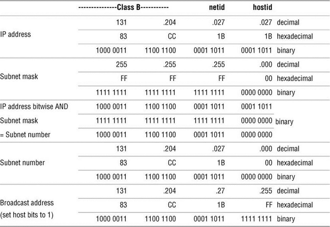
Table 8-2 Computations for IP address 131.204.027.027
CIDR: Classless Inter-Domain Routing
CIDR (pronounced “cider”) allows groups of addresses to be assigned to an organization or ISP and then further subdivided and parceled out. In addition, it helps prevent routing tables on Internet backbone providers from becoming too large to manage by consolidating arbitrary network ranges along bit boundaries.
IPv6 (page 293) is the solution to IPv4 address exhaustion. The trend is to reclaim older, large address blocks, if possible, and recycle them into groups of smaller address blocks. Larger blocks are allocated to ISPs, which in turn subdivide these blocks and allocate them to their customers. When you request an address block, your ISP usually gives you as many addresses as you need—and no more. The ISP aggregates one or more contiguous smaller blocks to satisfy your request. This aggregation is CIDR. Without CIDR, the Internet as we know it would not function.
For example, you might be allocated the 192.168.5.0/22 IP address block, which can support 210 hosts (32 – 22 = 10). Your ISP would set its routers so packets going to an address in that block would be sent to your network. Internally, your own routers might further subdivide this block of 1,024 potential hosts into four networks. Four networks require an additional two bits of addressing (22 = 4). You could therefore set up your router to support four networks with this allocation: 192.168.5.0/24, 192.168.6.0/24, 192.168.7.0/24, and 192.168.8.0/24. Each of these networks could then have 254 hosts. CIDR lets you arbitrarily divide networks and subnetworks into increasingly smaller blocks along the way. Each router has enough memory to keep track of the addresses it needs to direct and aggregates the rest.
This scheme uses memory and address space efficiently. For example, you could take 192.168.8.0/24 and further divide it into 16 networks with 14 hosts each. The 16 networks require four more bits (24 = 16), so you would have 192.168.8.0/28, 192.168.8.16/28, 192.168.8.32/28, and so on, up through the last subnet of 192.168.8.240/16, which would have the hosts 192.168.8.241 through 192.168.8.254.
![]() Hostnames
Hostnames
People generally find it easier to work with names than with numbers, so Linux provides several ways to associate hostnames with IP addresses. The oldest method is to consult a list of names and addresses stored in the /etc/hosts file:
$ cat /etc/hosts
127.0.0.1 localhost
130.128.52.1 gw–example.example.com gw–example
130.128.52.2 bravo.example.com bravo
130.128.52.3 hurrah.example.com hurrah
130.128.52.4 kudos.example.com kudos
localhost = 127.0.0.1
The address 127.0.0.1 is reserved for the special hostname localhost, which serves as a hook for the system’s networking software to operate on the local machine without going onto a physical network. The names of the other systems are shown in two forms: in a fully qualified domain name(FQDN) format that is unique on the Internet and as a nickname that is locally unique. Use of these names is a convention; the system does not check the contents of the hosts file.
NIS
As more hosts joined networks, storing these name-to-address mappings in a text file proved to be inefficient and inconvenient. The hosts file grew bigger and became impossible to keep up-to-date. To solve this problem Linux supports NIS (Network Information Service; Chapter 21), which was developed for use on Sun computers. NIS stores information in a database, making it easier to find a specific address, but it is useful only for host information within a single administrative domain. Hosts outside the domain cannot access the information. Also, by default NIS is not secure and is difficult to secure.
DNS
The solution to this dilemma is DNS (Domain Name Service; Chapter 24). DNS effectively addresses the efficiency and update issues by arranging the entire network namespace (page 1262) as a hierarchy. Each domain in the DNS manages its own namespace (addressing and name resolution), and each domain can easily query for any host or IP address by following the tree up or down the namespace until it finds the appropriate domain. By providing a hierarchical naming structure, DNS distributes name administration across the entire Internet.
Communicate over a Network
Many commands that you can use to communicate with other users on a single computer system have been extended to work over a network. Examples of extended utilities include electronic mail programs, information-gathering utilities, and communications utilities (e.g., Empathy). These utilities are examples of the UNIX philosophy: Instead of creating a new, special-purpose tool, modify an existing one.
Many utilities understand a convention for the format of network addresses: user@host (spoken as “user at host”). When you use an @ sign in an argument to one of these utilities, the utility interprets the text that follows as the name of a remote host. When you omit the @ sign, a utility assumes you are requesting information from or corresponding with someone on the local system.
If you frequently use more than one system over a network, you might find it difficult to keep track of which system you are interacting with at any particular moment. If you set your prompt to include the hostname of the current system, it will always be clear which system you are using. To identify the computer you are using, run hostname or give the command uname –n:
$ hostname
kudos
See page 361 for information on how you can change the prompt.
Mailing List Servers
A mailing list server (listserv8) allows you to create and manage an email list. An electronic mailing list provides a means for people interested in a particular topic to participate in an electronic discussion. One of the most powerful features of most list servers is their ability to archive email postings to the list, create an archive index, and allow users to retrieve postings from the archive based on keywords or discussion threads. Typically you can subscribe and unsubscribe from the list with or without human intervention. The owner of the list can restrict who can subscribe, unsubscribe, and post messages to the list. See page 762 for instructions on configuring the Mailman list server. Other popular list servers include LISTSERV (www.lsoft.com), phplist (www.phplist.com), Lyris (www.lyris.com), and Majordomo (www.greatcircle.com/majordomo). Fedora/RHEL maintains mailing lists and list archives for those mailing lists at www.redhat.com/mailman/listinfo. Use Google to search on linux mailing list to find other lists.
8. Although the term listserv is sometimes used generically to include many different list server programs, it is a specific product and a registered trademark of L-soft International, Inc.: LISTSERV (for more information visit www.lsoft.com).
Network Utilities
To realize the full benefits of a networked environment, it made sense to extend certain tools, some of which have already been described. The advent of networks also created a need for new utilities to control and monitor them, spurring the development of new tools that took advantage of network speed and connectivity. This section describes concepts and utilities for systems attached to a network.
Trusted Hosts
Although they are deprecated in favor of ssh (next), some commands, such as rcp and rsh, work only if the remote system trusts the local computer (that is, if the remote system knows the local computer and believes that it is not pretending to be another system). The /etc/hosts.equiv file lists trusted systems. For reasons of security, the root account does not rely on this file to identify trusted privileged users from other systems.
Host-based trust is largely obsolete. Because there are many ways to circumvent trusted host security, including subverting DNS systems and IP spoofing (page 1256), authentication based on IP address is insecure.
In a small homogeneous network it might be tempting to use these tools, and it might suffice. However, because ssh is easy to set up, provides privacy and authentication, and does not slow down modern CPUs appreciably, it is a good idea to use it instead of the older tools.
Security: Do not share your login account
It is poor practice to use a ~/.rhosts file to allow another user to log in as you from a remote system without knowing your password. Do not compromise the security of your files or the entire system by sharing your login account. Use ssh and scp instead of rsh and rcp.
OpenSSH Tools
The OpenSSH project provides a set of tools that replace rcp, rsh, and others with secure equivalents. These tools are installed by default in Fedora/RHEL and can be used as drop-in replacements for their insecure counterparts. The OpenSSH tool suite is covered in detail in Chapter 18.
![]() telnet: Logs In on a Remote System
telnet: Logs In on a Remote System
You can use the TELNET protocol to interact with a remote computer. The telnet utility (telnet package), a user interface to this protocol, is older than ssh and is not secure. Nevertheless, it might work where ssh (page 693) is not available (there is more non-UNIX support for TELNET access than for ssh access). In addition, some legacy devices, such as terminal servers, facilities infrastructure, and network devices, still do not support ssh. The following example shows Sam using telnet to log in on a remote system that is running the in.telnetd daemon (telnet-serverpackage):
[sam@guava ~]$ telnet plum
Trying 192.168.206.181...
Connected to plum.
Escape character is '^]'.
Fedora release 19 (Schrödinger’s Cat)
Kernel 3.10.3-300.fc19.x86_64 on an x86_64 (2)
plum login: sam
Password:
Last login: Tue Mar 8 13:20:14 from 192.168.206.180
...
[sam@plum ~]$ logout
Connection closed by foreign host.
[sam@guava ~]$
telnet versus ssh
When you connect to a remote UNIX or Linux system, telnet presents a textual login: prompt. Because telnet is designed to work with non-UNIX and non-Linux systems, it does not assume your remote username is the same as your local username (ssh does make this assumption). In some cases, telnet requires no login credentials.
Security: telnet is not secure
Whenever you enter sensitive information, such as your password, while you are using telnet, it is transmitted in cleartext and can be read by someone who is eavesdropping on the session.
In addition, telnet allows you to configure special parameters, such as how RETURNs or interrupts are processed (ssh does not give you this option). When using telnet between UNIX and/or Linux systems, you rarely need to change any parameters.
When you do not specify the name of a remote host on the command line, telnet runs in an interactive mode. The following example is equivalent to the previous telnet example:
[sam@guava ~]$ telnet
telnet> open plum
Trying 192.168.206.181...
Connected to plum.
Escape character is '^]'.
...
Before connecting to a remote system, telnet tells you what the escape character is; in most cases, it is ^] (where ^ represents the CONTROL key). When you press CONTROL-], you escape to telnet’s interactive mode. Continuing the preceding example:
[sam@guava ~]$ CONTROL-]
telnet> ?
Commands may be abbreviated. Commands are:
close close current connection
logout forcibly logout remote user and close the connection
display display operating parameters
mode try to enter line or character mode ('mode ?' for more)
...
telnet> close
Connection closed.
[sam@guava ~]$
When you enter a question mark in response to the telnet> prompt, telnet lists its commands. The close command ends the current telnet session, returning you to the local system. To get out of telnet’s interactive mode and resume communication with the remote system, press RETURN in response to a prompt.
Using telnet to Connect to Other Ports
By default telnet connects to port 23, which is used for remote logins. However, you can use telnet to connect to other services by specifying a port number. In addition to standard services, many of the special remote services available on the Internet use unallocated port numbers. Unlike the port numbers for standard protocols, these port numbers can be picked arbitrarily by the administrator of the service.
Although telnet is no longer commonly employed to log in on remote systems, it is still used extensively as a debugging tool by allowing you to communicate directly with a TCP server. Some standard protocols are simple enough that an experienced user can debug problems by connecting to a remote service directly using telnet. If you are having a problem with a network server, a good first step is to try to connect to it using telnet.
If you use telnet to connect to port 25 on a host, you can interact with SMTP. In addition, port 110 connects to the POP protocol, port 80 connects with a WWW server, and port 143 connects to IMAP. All these protocols are ASCII protocols and are documented in RFCs (page 1270). You can read the RFCs or search the Web for examples on how to use them interactively.
In the following example, a system administrator who is debugging a problem with email delivery uses telnet to connect to the SMTP port (port 25) on the server at example.com to see why it is bouncing mail from the spammer.com domain. The first line of output indicates which IP address telnet is trying to connect to. After telnet displays the Connected to smtpsrv.example.com message, the user emulates an SMTP dialog, following the standard SMTP protocol. The first line, which starts with helo, begins the session and identifies the local system. After the SMTP server identifies itself, the user enters a line that identifies the mail sender as user@spammer.com. The SMTP server’s response explains why the message is bouncing, so the user ends the session with quit.
$ telnet smtpsrv 25
Trying 192.168.1.1...
Connected to smtpsrv.example.com.
Escape character is '^]'.
helo example.com
220 smtpsrv.example.com ESMTP Sendmail 8.13.1/8.13.1; Wed, 4 May 2011 00:13:43 -0500 (CDT)
250 smtpsrv.example.com Hello desktop.example.com [192.168.1.97], pleased to meet you
mail from:user@spammer.com
571 5.0.0 Domain banned for spamming
quit
221 2.0.0 smtpsrv.example.com closing connection
The telnet utility allows you to use any protocol you want, as long as you know it well enough to type commands manually.
ftp: Transfers Files over a Network
FTP (File Transfer Protocol) is a method of downloading files from and uploading files to a remote system using TCP/IP over a network. Most Web browsers can download files from FTP servers. Some vendors use anonymous FTP (page 719) to accept uploaded debugging sessions or to allow clients to download firmware. FTP is not a secure protocol; use it only for downloading public information from a public server. See page 714 for more information on FTP security. Use one of the OpenSSH tools described in Chapter 18 for secure communication. Chapter 19 covers FTP clients and servers.
![]() ping: Tests a Network Connection
ping: Tests a Network Connection
The ping9 and ping6 utilities (referred to in this section as ping; read the story of ping at http://ftp.arl.mil/~mike/ping.html) send an ECHO_REQUEST packet to a remote computer. This packet causes the remote system to send back a reply. This exchange is a quick way to verify that a remote system is available and to check how well the network is operating, such as how fast it is or whether it is dropping data packets. The ping utility uses the ICMP (Internet Control Message Protocol) protocol. Without any options, ping tests the connection once per second until you abort execution using CONTROL-C. With the –c option ping tests the connection the number of times specified by the number that follows the option.
9. The name ping mimics the sound of a sonar burst used by submarines to identify and communicate with each other. The word ping also expands to packet internet groper.
$ ping -c 4 www.slashdot.org
PING www.slashdot.org (216.34.181.48) 56(84) bytes of data.
64 bytes from star.slashdot.org (216.34.181.48): icmp_seq=1 ttl=238 time=70.2 ms
64 bytes from star.slashdot.org (216.34.181.48): icmp_seq=2 ttl=238 time=72.6 ms
64 bytes from star.slashdot.org (216.34.181.48): icmp_seq=3 ttl=238 time=57.5 ms
64 bytes from star.slashdot.org (216.34.181.48): icmp_seq=4 ttl=238 time=71.2 ms
--- www.slashdot.org ping statistics ---
4 packets transmitted, 4 received, 0% packet loss, time 3024ms
rtt min/avg/max/mdev = 57.553/67.899/72.605/6.039 ms
This example shows that a connection to www.slashdot.org is answered by star.slashdot.org (www.slashdot.org is an alias for star.slashdot.org) and that that system is up and available over the network.
By default ping sends packets containing 64 bytes (56 data bytes and 8 bytes of protocol header information). In the preceding example, four packets were sent to the system star.slashdot.org as specified by the –c option. The four-part number in parentheses on each line is the remote system’s IP address. A packet sequence number (named icmp_seq) is also given. If a packet is dropped, a gap occurs in the number sequence. The round-trip time is listed last; it represents the time (in milliseconds) that elapsed from when the packet was sent from the local system to the remote system until the reply from the remote system was received by the local system. This time is affected by the distance between the two systems, network traffic, and the load on both computers. Before it terminates, ping summarizes the results, indicating how many packets were sent and received as well as the minimum, average, maximum, and mean deviation round-trip times it measured. Use ping6 to test IPv6 networks.
Tip: When ping cannot connect
If it is unable to contact the remote system, ping continues trying until you interrupt it by pressing CONTROL-C. A system might not answer for any of several reasons: The remote computer might be down, the network interface or some part of the network between the systems might be broken, a software failure might have occurred, or the remote machine might be set up (for reasons of security) not to return pings (try pinging www.microsoft.com or www.ibm.com).
![]() traceroute: Traces a Route over the Internet
traceroute: Traces a Route over the Internet
The traceroute and traceroute6 utilities (referred to in this section as traceroute; traceroute package) trace the route that an IP packet follows, including all intermediary points traversed (called network hops), to its destination (the argument to traceroute—a remote system). They display a numbered list of hostnames, if available, and IP addresses, together with the round-trip time it took for a packet to reach each router along the way and for the local system to receive a response. You can put this information to good use when you are trying to identify the location of a network bottleneck.
The traceroute utility has no concept of the path from one host to the next; instead, it simply sends UDP packets with increasing TTL (time to live) values. TTL is an IP header field that indicates how many more hops the packet should be allowed to make before being discarded or returned. Each router along the way inspects the TTL and decrements it by 1. When the TTL reaches 0 the router that has the packet sends back an ICMP TIME EXCEEDED to the local system, where traceroute records the IP address of the router that sent it back. The result is a list of hosts that the packet traveled through to get to its destination.
The traceroute utility can help solve routing configuration problems and locate routing path failures. When you cannot reach a host, use traceroute to discover which path the packet follows, how far it gets, and what the delay is.
The example on the next page shows the output of traceroute when it follows a route from a local computer to www.linux.org. The first line indicates the IP address of the target, the maximum number of hops that will be traced, and the size of the packets that will be used. Each numbered line contains the name and IP address of the intermediate destination, followed by the time it takes a packet to make a trip to that destination and back again. The traceroute utility sends three packets to each destination; thus three times appear on each line. Line 1 shows the statistics when a packet is sent to the local gateway (less than 3 milliseconds). Lines 4–6 show the packet bouncing around Mountain View (California) before it goes to San Jose. Between hops 13 and 14 the packet travels across the United States (San Francisco to somewhere in the East). By hop 18 the packet has found www.linux.org. The traceroute utility displays asterisks when it does not receive a response. Each asterisk indicates that traceroute has waited three seconds. Use traceroute6 to test IPv6 networks.
$ traceroute www.linux.org
traceroute to www.linux.org (198.182.196.56), 30 hops max, 38 byte packets
1 gw.localco.com. (204.94.139.65) 2.904 ms 2.425 ms 2.783 ms
2 covad-gw2.meer.net (209.157.140.1) 19.727 ms 23.287 ms 24.783 ms
3 gw-mv1.meer.net (140.174.164.1) 18.795 ms 24.973 ms 19.207 ms
4 d1-4-2.a02.mtvwca01.us.ra.verio.net (206.184.210.241) 59.091 ms d1-10-0-0-200.a03.
mtvwca01.us.ra.verio.net (206.86.28.5) 54.948 ms 39.485 ms
5 fa-11-0-0.a01.mtvwca01.us.ra.verio.net (206.184.188.1) 40.182 ms 44.405 ms 49.362 ms
6 p1-1-0-0.a09.mtvwca01.us.ra.verio.net (205.149.170.66) 78.688 ms 66.266 ms 28.003 ms
7 p1-12-0-0.a01.snjsca01.us.ra.verio.net (209.157.181.166) 32.424 ms 94.337 ms 54.946 ms
8 f4-1-0.sjc0.verio.net (129.250.31.81) 38.952 ms 63.111 ms 49.083 ms
9 sjc0.nuq0.verio.net (129.250.3.98) 45.031 ms 43.496 ms 44.925 ms
10 mae-west1.US.CRL.NET (198.32.136.10) 48.525 ms 66.296 ms 38.996 ms
11 t3-ames.3.sfo.us.crl.net (165.113.0.249) 138.808 ms 78.579 ms 68.699 ms
12 E0-CRL-SFO-02-E0X0.US.CRL.NET (165.113.55.2) 43.023 ms 51.910 ms 42.967 ms
13 sfo2-vva1.ATM.us.crl.net (165.113.0.254) 135.551 ms 154.606 ms 178.632 ms
14 mae-east-02.ix.ai.net (192.41.177.202) 158.351 ms 201.811 ms 204.560 ms
15 oc12-3-0-0.mae-east.ix.ai.net (205.134.161.2) 202.851 ms 155.667 ms 219.116 ms
16 border-ai.invlogic.com (205.134.175.254) 214.622 ms * 190.423 ms
17 router.invlogic.com (198.182.196.1) 224.378 ms 235.427 ms 228.856 ms
18 www.linux.org (198.182.196.56) 207.964 ms 178.683 ms 179.483 ms
Some firewalls block UDP/traceroute. If traceroute fails, try using the –T (sends TCP SYN packets) or –I (sends ICMP ECHO packets) option. Another useful tool is mtr (mtr package), which provides traceroute functionality plus information about dropped packets. The mtr utility is useful for debugging packet loss along a multi-hop network path.
![]() host and dig: Query Internet Nameservers
host and dig: Query Internet Nameservers
Given a name, the host utility looks up an IP address, or vice versa. The following example shows how to use host to look up the domain name of a machine, given an IP address:
$ host 64.13.141.6
6.141.13.64.in-addr.arpa domain name pointer ns.meer.net.
You can also use host to determine the IP address of a domain name:
$ host ns.meer.net
ns.meer.net has address 64.13.141.6
The dig (domain information groper) utility queries DNS servers and individual machines for information about a domain. A powerful utility, dig has many features you might never use. It is more complex than host. Chapter 24 on DNS has many examples of the use of host and dig.
whois: Looks Up Information About an Internet Site
The whois utility (whois package) queries a whois server for information about an Internet site. This utility returns site contact and InterNIC or other registry information that can help you track down the person who is responsible for a site: Perhaps that person is sending you or your company spam. Many sites on the Internet are easier to use and faster than whois. Use a browser and search engine to search on whois or go to www.networksolutions.com/whois or apps.db.ripe.net/search to get started.
When you do not specify a whois server, whois defaults to whois.internic.net. Use the –h option to whois to specify a different whois server. See the whois info page for more options and setup information.
To obtain information on a domain name, specify the complete domain name, as in the following example:
$ whois sobell.com
Domain Name: SOBELL.COM
Registrar: GODADDY.COM, INC.
Whois Server: whois.godaddy.com
Referral URL: http://registrar.godaddy.com
Name Server: NS1.HUNGERHOST.COM
...
Registrant:
Sobell Associates Inc
660 Market Street
Fifth Floor
San Francisco, California 94104
United States
Registered through: GoDaddy.com, Inc. (http://www.godaddy.com)
Domain Name: SOBELL.COM
Created on: 07-Apr-95
Expires on: 08-Apr-13
Last Updated on: 01-Mar-10
Administrative Contact:
Sobell, Mark sobell@meer.net
Sobell Associates Inc
660 Market Street
Fifth Floor
SAN FRANCISCO, California 94104
United States
18888446337 Fax -- 18888446337
Technical Contact:
W., Tim hostmaster@meer.net
meer.net
po box 390804
Mountain View, California 94039
United States
18888446337 Fax -- 18888446337
Domain servers in listed order:
NS1.HUNGERHOST.COM
NS2.HUNGERHOST.COM
Several top-level registries serve various regions of the world. You are most likely to use the following ones:
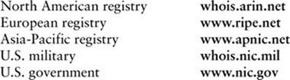
Distributed Computing
When many similar systems are part of a network, it is often desirable to share common files and utilities among them. For example, a system administrator might choose to keep a copy of the system documentation on one computer’s disk and to make those files available to remote systems. In this case, the system administrator configures the files so users who need to access the online documentation are not aware that the files are stored on a remote system. This type of setup, which is an example of distributed computing, not only conserves disk space but also allows you to update one central copy of the documentation rather than tracking down and updating copies scattered throughout the network on many different systems.
Figure 8-2 illustrates a fileserver that stores the system manual pages and users’ home directories. With this arrangement, a user’s files are always available to that user no matter which system the user logs in on. Each system’s disk might contain a directory to hold temporary files as well as a copy of the operating system. Chapter 22 contains instructions for setting up NFS clients and servers in networked configurations.
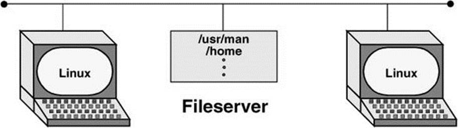
Figure 8-2 A fileserver
The Client/Server Model
Mainframe model
The client/server model was not the first computational model. First came the mainframe, which follows a one-machine-does-it-all model. That is, all the intelligence resides in one system, including the data and the program that manipulates and reports on the data. Users connect to a mainframe using terminals.
File-sharing model
With the introduction of PCs, file-sharing networks became available. In this scheme data is downloaded from a shared location to a user’s PC, where a program then manipulates the data. The file-sharing model ran into problems as networks expanded and more users needed access to the data.
Client/server model
In the client/server model, a client uses a protocol, such as HTTP or SCP, to request services, and a server provides the services the client requests. Rather than providing data files as the file-sharing model does, the server in a client/server relationship is a database that provides only those pieces of information the client needs or requests.
The client/server model dominates UNIX and Linux system networking and underlies most of the network services described in this book. FTP, NFS, DNS, email, and HTTP (the Web browsing protocol) all rely on the client/server model. Some servers, such as Web servers and browser clients, are designed to interact with specific utilities. Other servers, such as those supporting DNS, communicate with one another, in addition to answering queries from a variety of clients. Clients and servers can reside on the same or different systems running the same or different operating systems. The systems can be proximate or thousands of miles apart. A system that is a server to one system can turn around and act as a client to another. A server can reside on a single system or, as is the case with DNS, be distributed among thousands of geographically separated systems running many different operating systems.
Peer-to-peer model
The peer-to-peer (PTP) model, in which either program can initiate a transaction, stands in contrast to the client/server model. PTP protocols are common on small networks. For example, Microsoft’s Network Neighborhood and Apple’s Bonjour both rely on broadcast-based PTP protocols for browsing and automatic configuration. The Zeroconf multicast DNS protocol is a PTP alternative DNS for small networks. The highest-profile PTP networks are those used for file sharing, such as Kazaa and GNUtella. Many of these networks are not pure PTP topologies. Pure PTP networks do not scale well, so networks such as BitTorrent employ a hybrid approach.
DNS: Domain Name Service
DNS is a distributed service: Nameservers on thousands of machines around the world cooperate to keep the DNS database up-to-date. The database itself, which maps hundreds of thousands of alphanumeric hostnames to numeric IP addresses, does not exist in one place. That is, no system has a complete copy of the database. Instead, each system that runs DNS knows which hosts are local to that site and understands how to contact other nameservers to learn about other, nonlocal hosts.
Like the Linux filesystem, DNS is organized hierarchically. Each country has an ISO (International Organization for Standardization) country code designation as its domain name. (For example, AU represents Australia, IL is Israel, and JP is Japan; see countrycode.org for a complete list.) Although the United States is represented in the same way (US) and uses the standard two-letter Postal Service state abbreviations to identify the next level of the domain, only governments and a few organizations use these codes. Schools in the US domain are represented by a third- (and sometimes second-) level domain: k12. For example, the domain name for Myschool in New York state could be www.myschool.k12.ny.us.
Following is a list of the seven original top-level domains. These domains are used extensively within the United States and, to a lesser degree, by users in other countries:
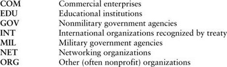
Recently, the following additional top-level domains have been approved for use. Visit en.wikipedia.org/wiki/List_of_Internet_top-level_domains for a complete, current list.
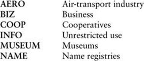
FQDN
Like Internet addresses, domain names were once assigned by the Network Information Center (NIC); now they are assigned by several companies. A system’s full name, referred to as its fully qualified domain name (FQDN), is unambiguous in the way that a simple hostname cannot be. The system okeeffe.berkeley.edu at the University of California at Berkeley (Figure 8-3) is not the same as one named okeeffe.moma.org, which might represent a host at the Museum of Modern Art. The domain name not only tells you something about where the system is located but also adds enough diversity to the namespace to avoid confusion when different sites choose similar names for their systems.
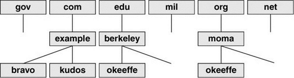
Figure 8-3 U.S. top-level domains
Unlike the filesystem hierarchy, the top-level domain name appears last (reading from left to right). Also, domain names are not case sensitive, so the names okeeffe.berkeley.edu, okeeffe.Berkeley.edu, and okeeffe.Berkeley.EDU refer to the same computer. Once a domain has been assigned, the local site is free to extend the hierarchy to meet local needs.
With DNS, email addressed to user@example.com can be delivered to the computer named example.com that handles the corporate mail and knows how to forward messages to user mailboxes on individual machines. As the company grows, its site administrator might decide to create organizational or geographical subdomains. The name delta.ca.example.com might refer to a system that supports California offices, for example, while alpha.co.example.com is dedicated to Colorado. Functional subdomains are another choice, with delta.sales.example.com andalpha.dev.example.com representing the sales and development divisions, respectively.
BIND
On Linux systems, the most common interface to the DNS is BIND (Berkeley Internet Name Domain). BIND follows the client/server model. On any given local network, one or more systems might be running a nameserver, supporting all the local hosts as clients. When it wants to send a message to another host, a system queries the nearest nameserver to learn the remote host’s IP address. The client, called a resolver, might be a process running on the same computer as the nameserver, or it might pass the request over the network to reach a server. To reduce network traffic and facilitate name lookups, the local nameserver maintains some knowledge of distant hosts. If the local server must contact a remote server to pick up an address, when the answer comes back, the local server adds that address to its internal table and reuses it for a while. The nameserver deletes the nonlocal information before it can become outdated. Refer to “TTL” on page 1278.
The system’s translation of symbolic hostnames into IP addresses is transparent to most users; only the system administrator of a networked system needs to be concerned with the details of name resolution. Systems that use DNS for name resolution are generally capable of communicating with the greatest number of hosts—more than would be practical to maintain in a /etc/hosts file or private NIS database. Chapter 24 covers setting up and running a DNS server.
Three common sources are referenced for hostname resolution: NIS, DNS, and system files (such as /etc/hosts). Linux does not ask you to choose among these sources; rather, the nsswitch.conf file (page 495) allows you to choose any of these sources, in any combination, and in any order.
![]() Ports
Ports
Ports are logical channels on a network interface and are numbered from 1 to 65,535. Each network connection is uniquely identified by the IP address and port number of each endpoint.
In a system that has many network connections open simultaneously, the use of ports keeps packets (page 1265) flowing to and from the appropriate programs. A program that needs to receive data binds to a port and then uses that port for communication.
Privileged ports
Services are associated with specific ports, generally with numbers less than 1024. These ports are called privileged (or reserved) ports. For security reasons, only a process running with root privileges can bind to a privileged port. A service run on a privileged port provides assurance that the service is being provided by someone with authority over the system, with the exception that any user on Windows 98 and earlier Windows systems can bind to any port. Commonly used ports include 22 (SSH), 23 (TELNET), 80 (HTTP), 111 (Sun RPC), and 201–208 (AppleTalk).
Security: Privileged ports do not provide absolute security
Any user who can gain root privileges can easily start a service on any port. Thus, it is necessary to treat privileged ports as a necessary but not sufficient component in a security policy and to be aware of which other systems are on the local network.
NIS: Network Information Service
NIS (Network Information Service) simplifies the maintenance of frequently used administrative files by keeping them in a central database and having clients contact the database server to retrieve information from the database. Just as DNS addresses the problem of keeping multiple copies of hosts files up-to-date, NIS deals with the issue of keeping system-independent configuration files (such as /etc/passwd) current. Although NIS has been functionally replaced by LDAP, LDAP is harder to configure, and so NIS is still in common use. Refer to Chapter 21 for coverage of NIS and LDAP.
NFS: Network Filesystem
The NFS (Network Filesystem) protocol allows a server to share selected local directory hierarchies with client systems on a heterogeneous network. Files on the remote fileserver appear as if they are present on the local system. Chapter 22 covers NFS.
Optional
![]() Network Services
Network Services
Linux Internet services are provided by daemons that run continuously or by a daemon that is started automatically by the systemd init daemon (page 438) when a service request comes in. The /etc/services file lists network services (for example, telnet, ftp, and ssh) and their associated numbers. Any service that uses TCP/IP or UDP/IP has an entry in this file. IANA (Internet Assigned Numbers Authority) maintains a database of all permanent, registered services. The /etc/services file usually lists a small, commonly used subset of services.
Most executable daemon files are stored in /usr/sbin. By convention the names of many daemons end with the letter d to distinguish them from utilities (one common daemon whose name does not end in d is sendmail). The prefix in. or rpc. is often used for daemon names. Give the command ls /usr/sbin/*d to see a list of many of the daemon programs on the local system. Refer to “Configuring Daemons (Services)” on page 445 for information about starting and stopping these daemons.
To see how a daemon works, consider what happens when you run ssh. The local system contacts the ssh daemon (sshd) on the remote system to establish a connection. The two systems negotiate the connection according to a fixed protocol. Each system identifies itself to the other, and they then take turns asking each other specific questions and waiting for valid replies. Each network service follows its own protocol.
Common Daemons
In addition to the daemons that support the utilities described in this chapter, many other daemons support system-level services that you will not typically interact with. Table 8-3 lists some of these daemons.
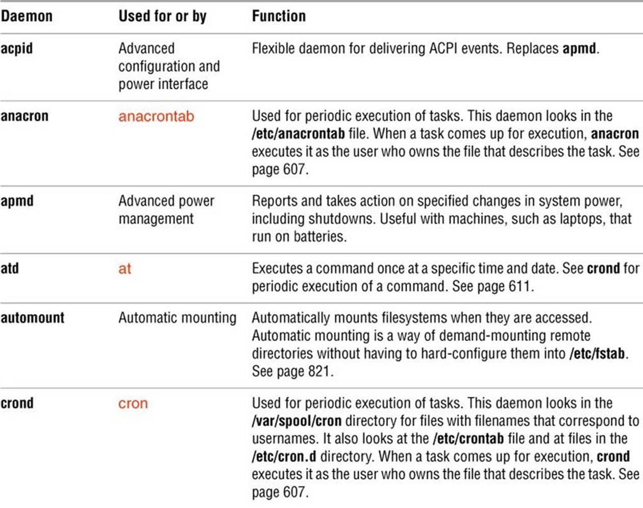
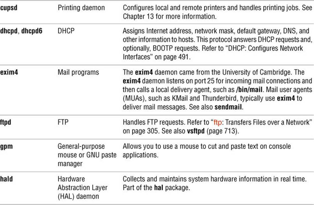
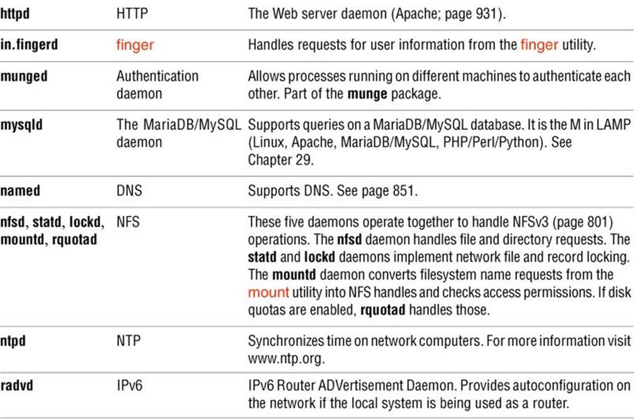
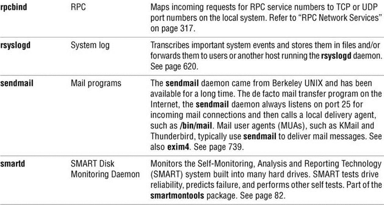
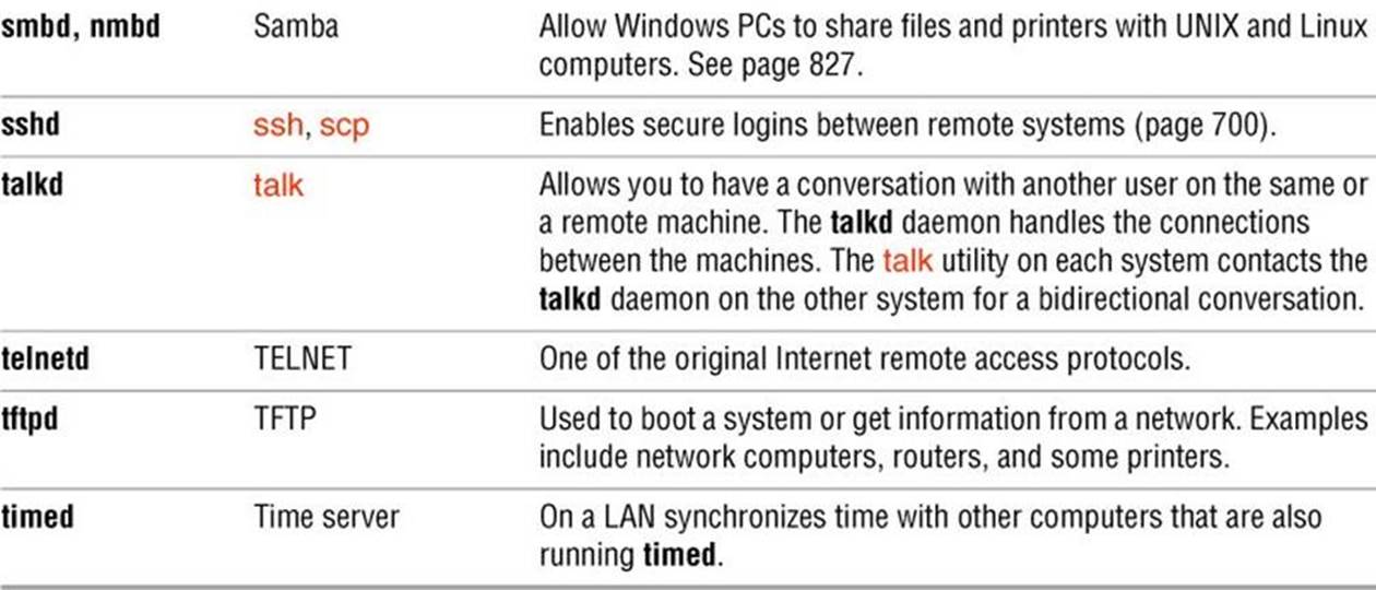
Table 8-3 Common daemons
Proxy Servers
A proxy is a network service that is authorized to act for a system while not being part of that system. A proxy server or proxy gateway provides proxy services; it is a transparent intermediary that relays communications back and forth between an application (e.g., a browser) and a server that usually resides outside of a LAN and frequently on the Internet. When more than one process uses the proxy gateway/ server, the proxy must keep track of which processes are connecting to which hosts/servers so that it can route the return messages to the proper process. The most commonly encountered proxies are email and Web proxies.
A proxy server/gateway insulates the local computer from all other computers or from specified domains by using at least two IP addresses: one to communicate with the local computer and one to communicate with a server. The proxy server/gateway examines and changes the header information on all packets it handles so it can encode, route, and decode them properly. The difference between a proxy gateway and a proxy server is that the proxy server usually includes cache (page 1241) to store frequently used Web pages so the next request for that page is available locally and quickly; a proxy gateway typically does not use cache. The terms “proxy server” and “proxy gateway” are frequently used interchangeably.
Proxy servers/gateways are available for such common Internet services as HTTP, HTTPS, FTP, SMTP, and SNMP. When an HTTP proxy sends queries from local systems, it presents a single organizationwide IP address (the external IP address of the proxy server/gateway) to all servers. It funnels all user requests to the appropriate servers and keeps track of them. When the responses come back, the HTTP proxy fans them out to the appropriate applications using each machine’s unique IP address, thereby protecting local addresses from remote/specified servers.
Proxy servers/gateways are generally just one part of an overall firewall strategy to prevent intruders from stealing information or damaging an internal network. Other functions, which can be either combined with or kept separate from the proxy server/gateway, include packet filtering, which blocks traffic based on origin and type, and user activity reporting, which helps management learn how the Internet is being used.
RPC Network Services
Much of the client/server interaction over a network is implemented using the RPC (Remote Procedure Call) protocol, which is implemented as a set of library calls that make network access transparent to the client and server. RPC specifies and interprets messages but does not concern itself with transport protocols; it runs on top of TCP/IP and UDP/IP. Services that use RPC include NFS and NIS. RPC was developed by Sun as ONC RPC (Open Network Computing Remote Procedure Calls) and differs from Microsoft RPC.
rpcbind
In the client/server model, a client contacts a server on a specific port (page 312) to avoid any mixup between services, clients, and servers. RPC has two possible ways of registering a port. The first works in the manner of a traditional daemon: The server binds to the port it wants to bind to but then registers with the RPC portmapper daemon (rpcbind) on the server. As an example, NFS uses this mechanism to always bind to port 2049. The client’s port is irrelevant most of the time, so it picks a random port.
More commonly, to avoid maintaining a long list of port numbers and to enable new clients/servers to start up without registering a port number with a central registry, when a server that uses RPC starts, it looks in /etc/rpc for the service number and then registers itself withrpcbind as just described. The rpcbind daemon assigns the server a TCP or UDP port number, and the server binds to that port. RPC servers typically use service numbers (/etc/rpc) that were defined by Sun, but the TCP or UDP port number it uses is random. When a client wants to connect to an RPC server, it first asks rpcbind on the server, which listens on port 111, for the name of the service it is interested in (e.g., mountd). If that service is registered, rpcbind returns the TCP or UDP port number of the server to the client. The client then contacts the RPC server daemon directly to finish the transaction.
Files
The /etc/rpc file (page 510) maps RPC service names to RPC numbers. The /etc/services file (page 511) maps system service names to TCP or UDP ports.
RPC client/server communication
The sequence of events for communication between an RPC client and server is as follows:
1. The client system needs to talk to a server application running on a remote system. The client system knows which system the server application is running on but not which port it is using. The client system looks for the service name in /etc/rpc to determine the service number.
2. The client system contacts rpcbind on port 111 of the remote system with the service number to ask which UDP or TCP port the server on the remote system is listening on.
3. The rpcbind daemon on the remote system checks which server applications have registered with it. If the service number the client system asked for is registered, the rpcbind daemon on the remote system returns the UDP or TCP port assigned to that server application.
4. The RPC libraries on the client system encode procedure calls and send them to the server application on the remote system on the specified port. (The client system issues a “read record from a file” request.)
5. The server application running on the remote system receives the call, sends it through the RPC libraries to decode it, and generates results. (The filesystem receives the “read record from file” request.)
6. The server application passes the results back through the RPC libraries, which encode the results, and then sends the encoded results to the client using the client’s registered port. (The read record is returned to the calling program.)
7. The client system receives the results, passes them through the RPC libraries for decoding, and presents the decoded results to the user or application that requested them.
If the rpcbind daemon stops, you must restart all RPC servers on the local system.
WWW: World Wide Web
The World Wide Web (WWW, W3, or the Web) provides a unified, interconnected interface to the vast amount of information stored on computers around the world. The idea that spawned the World Wide Web came from the mind of Tim Berners-Lee (www.w3.org/People/Berners-Lee) of the European Particle Physics Laboratory (CERN) in response to a need to improve communications throughout the high-energy physics community. The first-generation solution consisted of a notebook program named Enquire, short for Enquire Within Upon Everything (the name of a book from Berners-Lee’s childhood), which he created in 1980 on a NeXT computer and which supported links between named nodes. Not until 1989 was the concept proposed as a global hypertext project to be known as the World Wide Web. In 1990, Berners-Lee wrote a proposal for a hypertext project, which eventually produced HTML (Hypertext Markup Language), the common language of the Web. The World Wide Web program became available on the Internet in the summer of 1991. By designing the tools to work with existing protocols, such as FTP and gopher, the researchers who created the Web produced a system that is generally useful for many types of information and across many types of hardware and operating systems.
The WWW is another example of the client/server paradigm. You use a WWW client application, or browser, to retrieve and display information stored on a server that might be located anywhere on the local network or the Internet. WWW clients can interact with many types of servers. For example, you can use a WWW client to contact a remote FTP server and display the list of files it offers for anonymous FTP download. Most commonly you use a WWW client to contact a WWW server, which offers support for the special features of the World Wide Web that are described in the remainder of this chapter.
The power of the Web derives from its use of hypertext, a way to navigate through information by following cross-references (called links) from one piece of information to another. To use the Web effectively, you need to run interactive network applications. The first GUI for browsing the Web was a tool named Mosaic, which was released in February 1993. Designed at the National Center for Supercomputer Applications at the University of Illinois, its introduction sparked a dramatic increase in the number of users of the World Wide Web. Marc Andreessen, who participated in the Mosaic project at the University of Illinois, later cofounded Netscape Communications with the founder of Silicon Graphics, Jim Clark. The pair created Netscape Navigator, a Web client program that was designed to perform better and support more features than the Mosaic browser. Netscape Navigator enjoyed immense success and was a popular choice for exploring the World Wide Web. Important for Linux users is the fact that from its inception Netscape has provided versions of its tools that run on Linux.
Browsers
Mozilla (www.mozilla.org) is the open-source counterpart to Netscape and was first released in March 1998, based on Netscape 4 code. Since then, Mozilla has been under continuous development by employees of Netscape (now a division of AOL), Red Hat, and other companies and by contributors from the community. Firefox is the Web browser component of Mozilla. KDE offers Konqueror, an all-purpose file manager and Web browser. Other browsers include Safari (www.apple.com/safari), Chrome (www.google.com/chrome), Epiphany (projects.gnome.org/epiphany) and Opera (www.opera.com). Although each Web browser is unique, all of them allow you to move about the Internet, viewing HTML documents, watching videos, and retrieving files. If you do not use the X Window System, try a text browser, such as lynx or links. The lynx browser works well with Braille terminals.
Search Engines
Search engine is a name that applies to a group of hardware and software tools that help you search for World Wide Web sites that contain specific information. A search engine relies on a database of information collected by a Web crawler, a program that regularly looks through the millions of pages that make up the World Wide Web. A search engine must also have a way of collating the information the Web crawler collects so you can access it quickly, easily, and in a manner that makes it most useful to you. This part of the search engine, called an index, allows you to search for a word, a group of words, or a concept; it returns the URLs of Web pages that pertain to what you are searching for. Many different types of search engines are available on the Internet, each with its own set of strengths and weaknesses.
URL: Uniform Resource Locator
Consider the URL (Uniform Resource Locator) www.w3.org/Consortium/siteindex. The first component in the URL indicates the type of resource, in this case http (HTTP—Hypertext Transfer Protocol). Other valid resource names, such as https (HTTPS—secure HTTP) and ftp (FTP—File Transfer Protocol), represent information available on the Web using other protocols. Next come a colon and double slash (://). Frequently the http:// string is omitted from a URL in print, as you seldom need to enter it to reach the URL. The next element is the full name of the host that acts as the server for the information (www.w3.org/). The rest of the URL consists of a relative pathname to the file that contains the information (Consortium/siteindex). If you enter a URL in the location bar of a Web browser, the Web server returns the page, frequently an HTML (page 1254) file, pointed to by this URL.
By convention many sites identify their WWW servers by prefixing a host or domain name with www. For example, you can reach the Web server at the New Jersey Institute of Technology at www.njit.edu. When you use a browser to explore the World Wide Web, you might never need to enter a URL. However, as more information is published in hypertext form, you cannot help but find URLs everywhere—not just online in email messages and blogs, but also in newspapers, in advertisements, and on product labels.
URI
Whereas a URL indicates the location of a resource and a method of retrieving it (e.g., a network address and protocol), a URI (Uniform Resource Identifier) simply indicates something about the resource (e.g., an ISBN number). All URLs are URIs, but not all URIs are URLs. The terms are frequently used interchangeably because very few URIs that are not URLs are in common use.
Chapter Summary
A Linux system attached to a network is probably communicating on an Ethernet network, which might in turn be linked to other local area networks (LANs) and wide area networks (WANs). Communication between LANs and WANs requires the use of gateways and routers. Gateways translate the local data into a format suitable for the WAN, and routers make decisions about the optimal routing of the data along the way. The most widely used network, by far, is the Internet.
Basic networking tools allow Linux users to log in and run commands on remote systems (ssh, telnet, rsync) and copy files quickly from one system to another (scp, ftp/sftp). Other features, such as the Network Filesystem (NFS), were created to extend the basic UNIX model and to simplify information sharing.
Concern is growing about our ability to protect the security and privacy of machines connected to networks and of data transmitted over networks. Toward this end, many tools and protocols have been created: ssh, scp, HTTPS, IPv6, firewall hardware and software, VPN, and so on. Many of these tools take advantage of newer, more impenetrable encryption techniques. In addition, some weaker concepts (such as that of trusted hosts) and some tools (such as finger and rwho) have been deprecated in the name of security.
Computer networks offer two major advantages over other ways of connecting computers: They enable systems to communicate at high speeds, and they require few physical interconnections (typically one per system). The Internet Protocol (IP), the universal language of the Internet, has made it possible for dissimilar computer systems around the world to readily communicate with one another. Technological advances continue to improve the performance of computer systems and the networks that link them.
The rapid increase of network communication speeds in recent years has encouraged the development of many new applications and services. The World Wide Web provides access to vast information stores on the Internet and makes extensive use of hypertext links to promote efficient searching through related documents. It adheres to the client/server model that is so pervasive in networking. Typically the WWW client is local to a site or is made available through an Internet service provider. WWW servers are responsible for providing the information requested by their many clients.
Mozilla/Firefox is a WWW client program that has enormous popular appeal. Firefox and other browsers use a GUI to give you access to text, picture, and audio information: Making extensive use of these hypermedia simplifies access to and enhances the presentation of information.
Exercises
1. Describe the similarities and differences between these utilities:
a. scp and ftp
b. ssh and telnet
2. Describe two ways to find out who is logged in on some of the other machines attached to your network.
3. Explain the client/server model. Give three examples of services on Linux systems that take advantage of this model.
4. A software implementation of chess was developed by GNU and is available for free. How can you use the Internet to find and download this program?
5. What is the difference between the World Wide Web and the Internet?
6. If you have access to the World Wide Web, answer the following questions.
a. Which browser do you use?
b. What is the URL of the author of this book’s home page? How many links does it have?
c. Does your browser allow you to create bookmarks? If so, how do you create a bookmark? How can you delete one?
7. Give one advantage and two disadvantages of using a wireless network.
8. What is the fully abbreviated form of the IPv6 address 2620:0100:e000:0000:0000:0000:0000:8001?
9. IPv6 supports 128-bit addresses. What is the size of the host part of the address? How many hosts would that address space theoretically support on one LAN?
Advanced Exercises
10. Suppose the link between routers 1 and 2 is down in the Internet shown in Figure 8-1 on page 289. What happens if someone at site C sends a message to a user on a workstation attached to the Ethernet cable at site A? What happens if the router at site A is down? What does this tell you about designing network configurations?
11. If you have a class B IPv4 network and want to divide it into subnets, each with 126 hosts, which subnet mask should you use? How many networks will be available? What are the four addresses (broadcast and network number) for the network starting at 131.204.18?
12. Suppose you have 300 hosts and want to have no more than 50 hosts per subnet. What size of address block should you request from your ISP? How many /24 addresses would you need? How many subnets would you have left over from your allocation?
d. a. On the local system, find two daemons running that are not listed in this chapter and explain what purpose they serve.
b. Review which services/daemons are automatically started on your system and consider which you might turn off. Are there any services/daemons in the list in Table 8-3 on page 314 you would consider adding?
13. Determine if IPv6 is enabled on the local system by finding the link-local address of a network interface.
14. Use ssh to connect to a remote system on the local LAN using the remote system’s autoconfigured link-local IPv6 address. (Hint: To specify the network interface to use for link-local addresses, append %IFNAME to the end of the address, where IFNAME is the local operating system’s name for the interface.