Mastering Hyper-V 2012 R2 with System Center and Windows Azure (2014)
Chapter 3. Virtual Networking
This chapter covers the networking elements that enable virtual machines to communicate with each other and also with the rest of your environment. Features that are specific to virtual machines will be covered, but also network technologies in the operating system that can bring additional benefit.
Windows 2012 introduced network virtualization, which closes the remaining gap between virtualization and the goal of complete abstraction of the virtual machine from the underlying fabric. Network virtualization allows virtual machines to be abstracted from the physical network fabric, allowing complete isolation between virtual networks and the ability to use IP schemes independently of the physical network fabric. This technology will be covered in detail along with all the various options available to you.
In this chapter, you will learn to
· Architect the right network design for your Hyper-V hosts and virtual machines using the options available
· Identify when to use the types of NVGRE Gateways
· Leverage SCVMM 2012 R2 for many networking tasks
Virtual Switch Fundamentals
A typical server has one or more network adapters that are configured with an IPv4 and IPv6 address, either statically or dynamically, using services such as Dynamic Host Configuration Protocol (DHCP). The server may be part of a VLAN to provide isolation and control of broadcast traffic. It may require different network connections to connect to different networks, such as a separate, nonrouted network for cluster communications between servers in a failover cluster, a separate network for iSCSI traffic; a separate management network; and so on. With virtualization, the requirements for network connectivity is just as important as with a physical server. However, there are additional options available because essentially there are multiple server instances on a single physical asset, and in some cases they just need to communicate with each other and not externally to the virtualization host.
Three Types of Virtual Switch
Virtual machines have a number of virtualized resources, and one type is the virtual network adapter (as discussed in the previous chapter, there are actually two types of network adapter for a generation 1 virtual machine, but their connectivity options are the same). One or more virtual network adapters are added to a virtual machine and then each virtual adapter is attached to a virtual switch that was created at the Hyper-V host level. A Hyper-V host can have many virtual switches created. There are three types of virtual switches available: external, internal, and private, as shown in Figure 3.1.
1. External Virtual Networks
These are bound to a physical network card in the host, and virtual machines have access to the physical network via the physical NIC, which is linked to the external switch the virtual network adapter is connected to. Virtual machines on the same virtual switch can also communicate with each other. If they are on different switches that can communicate through the physical network, through routing, then they can also communicate. The virtual machines each see a virtual network device, and the Hyper-V host still sees the network adapter—however, it will no longer use it. The network device on the Hyper-V host is the physical NIC, which is bound only to the Hyper-V extensible virtual switch, which means it is being used by a Hyper-V virtual switch.
It is also possible when creating a virtual switch to enable the Hyper-V host itself, the management OS, to continue using the network adapter even though it has been assigned to a virtual switch. Sharing the adapter works by actually creating a virtual network adapter in the management partition that is connected to the Hyper-V virtual switch so all communication still goes through the virtual switch, which exclusively owns the physical network adapter. In Windows Server 2012, it's actually possible to create multiple virtual network adapters in the management partition, which opens up some new configuration options and scenarios that I will cover later in this chapter. If you had only a single network adapter in the Hyper-V host, you should definitely select the option to share the network adapter with the management operating system. The option to share the network adapter can be enabled or disabled at any time after the external switch has been created.
2. Internal Virtual Networks These are not bound to a physical NIC and so cannot access any machine outside the physical server. An internal network is visible to the Hyper-V host and the virtual machines, which means it can be used for communication between virtual machines and between virtual machines and the Hyper-V host. This can be useful if you are hosting services on the management partition, such as an iSCSI target, that you wish the virtual machines to be able to use. On both the Hyper-V host and virtual machines, a network device will be visible that represents the internal virtual network.
3. Private Virtual Networks These are visible only on virtual machines and are used for virtual machines to communicate with each other. This type of network could be used for virtual machines that are part of a guest cluster, and the private network could be used for the cluster network, providing all hosts in the cluster are running on the same Hyper-V host.
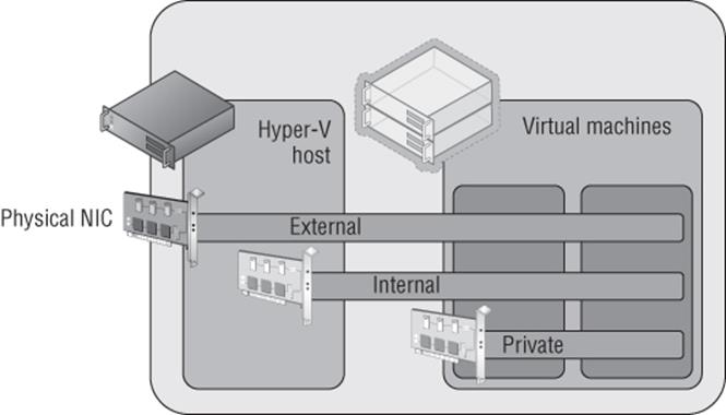
Figure 3.1 The three types of virtual switches available in Hyper-V
In most cases an external switch will be used because most virtual machines will require communications beyond the local Hyper-V host with internal and private networks used in testing and niche scenarios, such as the guest cluster that is confined to a single host. However, most likely if you were creating a production guest cluster in virtual machines, you would want them distributed over multiple Hyper-V hosts to protect against a host failure—in which case an external switch would be required.
A single physical network adapter can only be bound to a single external switch, and in production environments it would be common to use NIC teaming on the Hyper-V host. This would allow multiple network adapters to be bound together and surfaced to the operating system as a single teamed network adapter, which provides resiliency from a network adapter failure but also potentially provides aggregated bandwidth, allowing higher speed communications (there are many caveats around this, which I will cover later in this chapter when I cover NIC teaming in detail). A teamed network adapter can also be used and bound for an external switch with Hyper-V, giving all the virtual network adapters connected to that switch additional resiliency.
If you have different network adapters in a host and they connect to different networks (which may, for example, use VLANs to isolate traffic), then if virtual machines need access to the different networks, you would create multiple external virtual switches, with each bound to the physical network adapter connected to one of the various networks. It may seem obvious, but virtual machines can communicate only with the other services that are available on that physical network or can be routed via that network. Effectively, you are just expanding the connectivity of the physical network adapter to virtual machines via the virtual switch.
Many virtual machines can be connected to the same virtual networks, and one nice feature is that if multiple virtual machines on the same Hyper-V host are connected to the same external network and communicate over that network, the traffic never actually goes to the physical network adapter. The Hyper-V networking stack is smart enough to know that the traffic is going to another VM connected to the same switch and directly passes the traffic to the VM without ever touching the physical network adapter or physical network.
When you start creating virtual switches, it's important to use a consistent naming scheme across all of your various hosts for the switches. This is important because when a virtual machine is moved between Hyper-V hosts, it will look for a virtual switch with the same name as its existing virtual switch connection on the target host. If there is not a matching virtual switch, the virtual network adapter will become disconnected and therefore the virtual machine will lose connectivity. This is critical in failover clusters where virtual machines can freely move between nodes in the cluster, but with the Windows Server 2012 capability of moving virtual machines between any host with no shared resources and no downtime, it's important to have consistent virtual switch naming between all Hyper-V hosts. Take some time now to think about a good naming strategy and stick to it.
It's also possible to create access control lists, called extended port access control lists, within the virtual switch to allow and block communication between different virtual machines connected to the switch based on IP address, protocol, and port. Additionally stateful rules can be created to allow communication only when certain conditions are met. Microsoft has a detailed walk-though on using the ACLs at the following location:
http://technet.microsoft.com/en-us/library/dn375962.aspx
Creating a Virtual Switch
When the Hyper-V role is enabled on a server, an option is given to create an external switch by selecting a network adapter on the host. If this option is chosen, then a virtual switch will already be present on the host and it will be automatically configured to allow the management operating system to share the adapter, so an extra Hyper-V virtual Ethernet adapter will be present on the Hyper-V host. In general, I prefer not to create the virtual switches during Hyper-V role installation but to configure them postinstallation. Also, as you will read later, if your deployment is a production deployment and you're using System Center, then Virtual Machine Manager can do all of the switch configuration for you. I will, however, walk you through manually configuring virtual switches:
1. Launch Hyper-V Manager.
2. Select the Virtual Switch Manager action from the actions pane.
3. In the navigation pane, select New Virtual Network Switch, and in the details pane, select the type of virtual switch to create. In this case, select External and click the Create Virtual Switch button.
4. Replace the default New Virtual Switch name with a meaningful name that matches the naming standard for switches you have selected, such as, for example, External Switch. Optionally, notes can be entered.
5. If the switch type is external, the specific network adapter or the NIC team that will be bound to the virtual switch must be selected from the list of available network adapters on the system, as shown in Figure 3.2. Note that the type of switch can be changed in this screen by selecting another type of network, such as internal or private. Also note that network adapters/teams bound to other switches are still listed, but the creation will fail if they are selected.
By default the “Allow management operating system to share this network adapter” option is enabled, which creates the virtual network adapter on the management partition, enabling the Hyper-V host to continue accessing the network through the new virtual switch that is bound to the network adapter. However, if you have a separate management network adapter or if you will create it manually later, then disable this option by unchecking the box. If you uncheck this box, you will receive a warning when the switch is being created that you will lose access to the host unless you have another network adapter used for management communication. The warning is shown to protect you from disabling anyway to communicate with the host.
6. If you plan to use SR/IOV, check the Enable Single-Root I/O Virtualization (SR-IOV) box. This cannot be changed once the switch is created. (SR-IOV will be covered later. It's a technology found in newer, advanced networking equipment and servers that allows virtual machines to directly communicate with the networking equipment for very high-performance scenarios.)
7. If the option to allow the management operating system to use the network adapter was selected, it is possible to set the VLAN ID used by that network adapter on the host operating system through the VLAN ID option by checking Enable Virtual LAN Identification For Management Operating System and then entering the VLAN ID. Note that this does not set the VLAN ID for the switch but rather for the virtual network adapter created on the management partition.
8. Once all options are selected, click the OK button and the switch will be created (this is where the warning will be displayed if you unchecked the option to allow the management operating system to use the adapter).
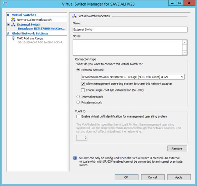
Figure 3.2 Primary configuration page for a new virtual switch
Creating switches is also possible using PowerShell, and the following commands will create an external (without sharing with the management operating system), internal, and private switch and then list switches that are of type External:
#Create new external (implicit external as adapter passed)
New-VMSwitch -Name "External Switch" -Notes "External Connectivity"¿
-NetAdapterName "VM NIC" -AllowManagementOS $false
#Create new internal (visible on host) and private (vm only)
New-VMSwitch -Name "Internal Switch" -SwitchType Internal
New-VMSwitch -Name "Private Switch" -SwitchType Private
Once a switch is created, it can be viewed through the Virtual Switch Manager and modification of the properties is possible. A virtual switch's type can be changed at any time unless it is an external virtual switch with SR/IOV enabled. In that case, its type cannot be changed without deleting and re-creating it. Virtual network adapters can be connected to the switch through the properties of the virtual network adapter.
Extensible Switch
The Hyper-V extensible switch provides a variety of capabilities that can be leveraged by the virtual network adapters that are connected to the virtual switch ports, including features such as port mirroring, protection from rogue DHCP servers and router advertisements, bandwidth management, support for VMQ, and more. However, there is still only a specific set of capabilities that cover the majority of scenarios and customer requirements; they might not cover every requirement that different clients may have. Those familiar with VMware may have heard of the Cisco Nexus 1000V, which is available for ESX and essentially replaces the VMware switching infrastructure completely. The Cisco Nexus 1000V is the only model VMware supports, and the challenge is that not many vendors have the resources available to write a complete virtual switching infrastructure. Microsoft went a different direction in Windows Server 2012.
Windows Server 2012 introduces the extensible switch for Hyper-V. With the extensible switch, it's possible for third parties to plug into the Hyper-V virtual switch at various points without having to completely replace it, thus making it far easier for organizations to bring additional value. It was common to have the ability to add functionality into the Hyper-V switch such as enhanced packet filtering capabilities, firewall and intrusion detection at the switch level, switch forwarding, and utilities to help sniff data on the network. Consider that Windows already has a rich capability around APIs and interfaces for third parties to integrate with the operating system, specifically Network Device Interface Specification (NDIS) filter drivers and Windows Filtering Platform (WFP) callout drivers. The Hyper-V extensible switch uses these exact same interfaces that partners are already utilizing, making it possible for vendors to easily adapt solutions to integrate directly into the Windows 2012 and above extensible switch. InMON's sFlow monitoring extension allows great trending analysis of traffic, NEC has OpenFlow extension, and 5Nine has a complete firewall extension for the Hyper-V extensible switch.
There are four specific types of extensions for the Hyper-V switch, which are listed in Table 3.1.
Table 3.1 Types of extension for Hyper-V virtual switch
Extension |
Purpose |
Potential Examples |
Extensibility Component |
Network packet inspection |
Inspecting network packets, but not altering them |
Network monitoring |
NDIS filter driver |
Network packet filter |
Injecting, modifying, and dropping network packets |
Security |
NDIS filter driver |
Network forwarding |
Third-party forwarding that bypasses default forwarding |
Virtual Ethernet Port Aggregator (VEPA) and proprietary network fabrics |
NDIS filter driver |
Firewall/Intrusion detection |
Filtering and modifying TCP/IP packets, monitoring or authorizing connections, filtering IPsec-protected traffic, and filtering RPCs |
Virtual firewall and connection monitoring |
WFP callout driver |
Multiple extensions can be enabled on a virtual switch, and the extensions are leveraged for both ingress (inbound) and egress (outbound) traffic. One big change from Windows Server 2012 is that in Windows Server 2012 R2, the Hyper-V Network Virtualization (HNV) module is moved into the virtual switch instead of being external to the virtual switch. This enables switch extensions to inspect both the provider and customer headers (more on this later, but for now the provider header is the packet that enables Network Virtualization to function across physical networks and the customer header is the IP traffic that virtual machines in a virtual network actually see) and therefore work with Network Virtualization. The move of the Network Virtualization module also enables third-party forwarding extensions like the Cisco Nexus 1000V to work with Network Virtualization, which wasn't the case in Windows Server 2012. And yes, Cisco has a Nexus 1000V for Hyper-V that works with the Hyper-V switch instead of completely replacing it. This is important because many organizations use Cisco networking solutions and the Nexus 1000V enables unified management of both the physical and virtual network environment through the Cisco network management toolset.
The Windows Server 2012 R2 extensible switch also supports hybrid forwarding, which allows packets to be forwarded to different forwarding agents based on the packet type. For example, suppose the Cisco Nexus 1000V extension (a forwarding agent) was installed. With hybrid forwarding, if network virtualization traffic is sent through the switch, it would first go through the HNV module and then to the forwarding agent, the Nexus 1000V. If the traffic was not network virtualization traffic, then the HNV module would be bypassed and the traffic sent straight to the Nexus 1000V.
Figure 3.3 best shows the extensible switch and how traffic flows through the extensions. Notice that the traffic flows completely through all layers of the switch twice, once “inbound” into the switch (which could be from a VM or from external sources) and once “outbound” from the switch (which could be to a VM or to an external source).
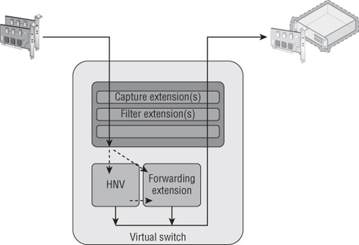
Figure 3.3 How traffic flows through the extensible switch and registered extensions for the inbound path
Extensions to the switch are provided by the third parties and installed onto the Hyper-V server and then enabled on a per-virtual-switch basis once installed. The process to enable an extension is simple. Open the Virtual Switch Manager and select the virtual switch for which you want to enable extensions. Then select the Extensions child node of the virtual switch. In the extensions area of the dialog, check the box for the extension(s) you wish to enable, as shown in Figure 3.4. That's it! The extensions are now enabled. InFigure 3.4, a number of different extensions types can be seen, and two are not part of standard Hyper-V: Microsoft VMM DHCPv4 Server Switch Extension and sFlow Traffic Monitoring. When enabled, the sFlow Traffic Monitoring extension sends trending information and more to the sFlowTrend tool for graphical visualization and analysis. The Microsoft VMM DHCPv4 Server Switch Extension is a filter that, when it sees DHCP traffic, intercepts the requests and utilizes IP pools within Virtual Machine Manager to service DHCP requests over the virtual switch instead of using standard DHCP services, enabling VMM to manage all IP configuration.
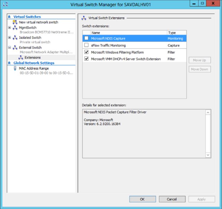
Figure 3.4 Enabling extensions for a virtual switch in Hyper-V
VLANs and PVLANS
In most datacenters it is not uncommon to see widespread use of virtual LANs(VLANs), which allow for isolation of traffic without the need to use physical separation, such as using different switches and network adapters for the different types of isolated networks. While physical separation works, it is costly to maintain the additional physical infrastructure in terms of hardware, power, and even cooling in the datacenter. It can also be complex to manage large numbers of isolated physical network topologies.
Understanding VLANs
A VLAN is a layer 2 technology that primarily adds the ability to create partitions in the network for broadcast traffic. Normally networks are separated using devices such as routers, which control the transmission of traffic between different segments (a local area network, or LAN) of the network. However, a VLAN allows a single physical network segment to be virtually partitioned so that different VLANs cannot communicate with each other and broadcast traffic such as ARP (to resolve IP addresses to MAC addresses) would not cross VLANs. A great example of explaining the broadcast boundary nature of a VLAN is to consider 10 machines plugged into a single switch and 1 of those machines is a DHCP server. Typically all 9 of the other machines plugged into that switch would be able to get an IP address from the DHCP server. If VLANs were configured and the DHCP server and a few of the machines were put in a specific VLAN, then only the machines in the same VLAN as the DHCP server would be able to get an IP address from the DHCP server. All the other machines not part of that VLAN would not be able to contact the DHCP server and would require another method for IP configuration.
Additionally, through network hardware configuration it is possible for a single VLAN to actually cross different physical network segments and even locations, allowing machines that are physically distributed to act and communicate as if they were on a single physical network segment. The VLAN is at a high level creating virtual LANs that are abstracted from the physical location. For VLANs to communicate with each, other layer 3 technologies (IP) would be used for IP-level routing.
The partitioning of communication and broadcast traffic enables VLANs to provide a number of key features to an environment that make VLANs an attractive technology to implement:
· Separate broadcast domains. This seems obvious, but it can be a huge benefit for larger networks where the amount of broadcast traffic may be causing network performance issues. This also enables a single network to be divided into separate networks as required.
· Isolation between machines. VLANs enable partitions between different groups of servers, which may be required in scenarios such as different departments, Internet-facing networks, hosting providers to separate clients, and more.
· Administrative help. With VLANs, it's possible to move servers between locations but maintain their VLAN membership, avoiding reconfiguration of the host.
· A separation of physical networks from virtual networks. This enables virtual LANs to span different physical network segments.
Typically a VLAN and IP subnet has a one-to-one mapping, although it is possible to have multiple subnets within a single VLAN. Remember, though, that a VLAN represents a broadcast boundary, which means a single subnet cannot cross VLANs because by definition, an IP subnet represents a group of machines with direct communication that rely on broadcasts for translating IP addresses to MAC addresses using ARP.
While VLANs seem like a useful technology, and they are, there are some drawbacks and complexity to their configuration. First, consider a typical datacenter network switch configuration with a number of racks of servers. There are typically two types of switches involved; servers within a rack connect to the top-of-rack (ToR) switch in each rack and then connect to aggregation switches. The configuration in Figure 3.5 shows three VLANs in use by Hyper-V servers for different virtual machines, which in this example are VLANs 10, 20, and 30. Notice that machines in VLAN 10 span different racks, which requires configuration of the VLAN in not just the ToR but also aggregation switches. For VLANs 20 and 30, all the VMs are in the same rack, so while the ports from the hosts in the rack to the ToR require access for VLAN 10, 20, and 30, the aggregation switches will see only VLAN 10 traffic passed to them, which is why only VLAN 10 has to be configured.
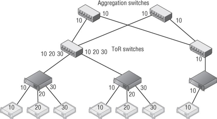
Figure 3.5 Three VLANs in a two-rack configuration. For redundancy, each ToR has a connection to two separate aggregation switches.
Notice in Figure 3.5 that single ports can be configured to allow traffic from different VLANs (ports between switches are known as trunk ports because they are configured for all the VLAN traffic that has to be passed between them). However, even normal ports to a host can be configured to allow multiple VLANs, which is especially necessary with virtualization where different virtual machines on a single host may be part of different VLANs. Realize that even in this very basic configuration with only two racks, the VLAN configuration can require changes on the network infrastructure at multiple points such as the ToRs and aggregation switches.
Consider now if a new virtual machine is required for VLAN 20 but there is no capacity in the first rack, which requires the virtual machine to be created in the second rack, as shown in Figure 3.6. This requires changes to the second rack ToR and both aggregation switches. Imagine there are hundreds of racks and hundreds of VLANs. This type of VLAN change can be very complex and take weeks to actually implement because all of the VLAN configuration is static and requires manual updating, which makes the actual network a bottleneck in provisioning new services. You've probably heard of some VLAN configuration problems, although you didn't know it was a VLAN configuration problem. Some of the major “outages” of Internet-facing services have been caused not by hardware failure but actually by changes to network configuration that “went wrong” and take time to fix, specifically VLANs! Suppose you wish to use Live Migration to easily move virtual machines between hosts and even racks; this adds even more complexity to the VLAN configurations to ensure that the virtual machines don't lose connectivity when migrated.
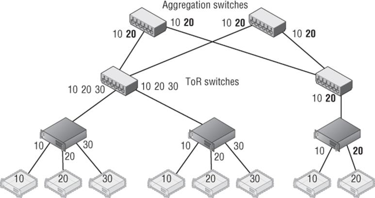
Figure 3.6 New VM in VLAN 20 added to the host in the second rack and the changes to the switch VLAN configuration required
Tagged vs. Untagged Configuration
One thing regarding VLANs confused me when I first started with network equipment (well, lots of things confused me!), and that was whether to configure ports as tagged or untagged, which are both options when configuring a port on a switch.
When a port is configured as tagged, it means that port expects the traffic to already be tagged with a VLAN ID. This means the VLAN must be configured at the host connected to the port or at a VM level running on the host. Additionally, for a tagged port it is possible to configure inclusions and exclusions for the VLAN IDs accepted on that port. For example, a port configured as tagged may be configured to allow only VLAN ID 10 through. A trunk port would be configured with all the VLAN IDs that needed to be passed between switches.
When a port is configured as untagged, it means the port does not require traffic to be tagged with a VLAN ID and will instead automatically tag traffic with the default VLAN ID configured on the port for traffic received from the host and going out to other hosts or switches. For inbound traffic to the switch going to the host, the VLAN ID is stripped out and the packet is sent to the host. On many switches, by default all ports are configured as untagged with a default VLAN ID of 1.
To summarize:
Tagged = Port expects traffic to be tagged when receiving.
Untagged = Port expects traffic to not be tagged and will apply a default VLAN ID. Any traffic that has a VLAN tag will be dropped.
Another limitation with VLANs is the number of VLANs that can be supported in an environment, which is 4,095 because the VLAN ID in the header is 12 bits long and 1 VLAN ID is not usable. So 4,095 is the theoretical number, but most switches limit the number of usable VLANs to 1,000. This may still seem like a lot, but if an organization is a host with thousands of clients, then the 1,000 limitation, or even 4,095, would make it an unusable solution. Also remember the complexity issue. If you have a 1,000 VLANs over hundreds of servers, managing them would not be a pleasant experience!
VLANs and Hyper-V
Even with the pain points of VLANs, the reality is you are probably using VLANs, will still use them for some time, and want to use them with your virtual machines. It is completely possible to have some virtual machines in one VLAN and other virtual machines in other VLANs. While there are different ways to perform configuration of VLANs, with Hyper-V there is really one supported and reliable way to use them and maintain manageability and troubleshooting ability:
· Configure the switch port that is connected to the Hyper-V host in tagged mode and configure it to have inclusions for all the VLAN IDs that will be used by VMs connected to that host. Another option is to run the port essentially in a trunk type mode and allow all VLAN IDs through the port to avoid potential configuration challenges when a new VLAN ID is used by a VM on the host. Definitely do not configure the port as untagged with any kind of default VLAN ID. I cannot stress this enough. If a switch port is configured as untagged and it receives traffic that is tagged, that traffic will be dropped even if the VLAN ID matches the VLAN the port has been configured to set via the untagged configuration.
· Do not set a VLAN ID on the physical NIC in the Hyper-V host that is used by the virtual switch that will be connected to the virtual machines.
· If you are using NIC Teaming, have only a single, default mode team interface configured on the team.
· Run all communications through the Hyper-V virtual switch and apply the VLAN ID configuration on the virtual switch ports that correspond to the virtual network adapters connected to the virtual switch.
This actually makes configuring a VLAN quite simple. The only VLAN configuration performed in the Hyper-V environment is within the properties of the virtual network adapter as shown in Figure 3.7, where I set the VLAN ID for this specific network adapter for the virtual machine. The Set-VMNetworkAdapterVlan PowerShell cmdlet can also be used to set the VLAN ID for a virtual network adapter, as in the following example:
Set-VMNetworkAdapterVlan –VMName test1 –Access –VlanId 173
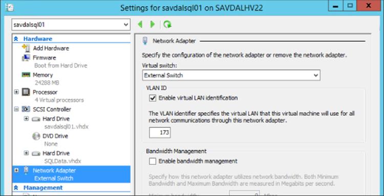
Figure 3.7 Setting the VLAN ID for a virtual machine's network adapter
If you refer back to Figure 3.2, there may be something that seems confusing and that is the option to configure a VLAN ID on the virtual switch itself. Does this setting then apply to every virtual machine connected to that virtual switch? No. As the explanation text in the dialog actually explains, the VLAN ID configured on the virtual switch is applied to any virtual network adapters created in the management OS for the virtual switch, which allows the management OS to continue using a physical network adapter that has been assigned to a virtual switch. The VLAN ID configured on the switch has no effect on virtual machine VLAN configuration.
Note that if you do not require different VLAN IDs within the Hyper-V environment and all virtual machines effectively will use the same VLAN ID, then no VLAN configuration is required at the Hyper-V host or virtual machine level. Simply use untagged at the switch and configure whatever VLAN ID you wish all traffic to be tagged with as the default. The previous configuration is when you need different VLAN IDs for the various virtual machines and management OS.
PVLANs
With all the scalability limitations of VLANs, you may wonder how large organizations and hosters specifically handle thousands of clients, which is where private VLANs (PVLANs) are a key feature. Through the use of only two VLAN IDs that are paired, PVLANs enable huge numbers of different environments to remain isolated from each other.
PVLANs enable three modes, as shown in Figure 3.8: isolated, community, and promiscuous. The primary mode that will be used with PVLANs is isolated; no direct communication is possible between hosts that are in isolated mode, but they can talk to their gateway and therefore out to the Internet and other promiscuous resources. This mode is useful if there are many different tenants that have only one host/VM each. Think about that large hosting company that hosts millions of VMs that don't need to communicate with each other or a hotel with 1,000 rooms. Also consider many workloads behind a load balancer that don't need to communicate with each other. Using PVLANs would stop the servers behind the load balancer from being able to communicate with each other, which would provide protection if one of them were compromised in some way, making it very useful for Internet-facing workloads. PVLANs are a great way to isolate every port from every other with only two VLANs required.
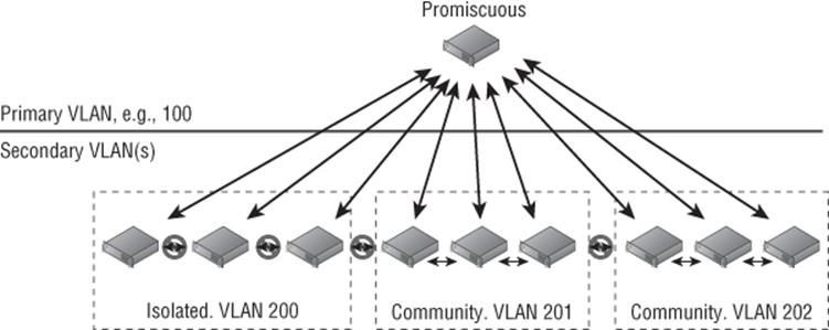
Figure 3.8 PVLAN overview and the three types
Community mode enables multiple hosts in the same community to communicate with each other. However, each community requires its own second VLAN ID to use with the shared primary VLAN ID. Finally, there are hosts in promiscuous mode that can communicate with hosts in isolated or community mode. Promiscuous PVLANs are useful for servers that are used by all hosts—perhaps they host a software share or updates that can be used by all.
Hyper-V supports all three PVLAN modes, but this is not exposed through the graphical Hyper-V Manager and instead all configuration is done in PowerShell using the Set-VMNetworkAdapterVlan cmdlet. Remember that each VLAN can be used as the primary VLAN of only one isolated PVLAN, so ensure that different VLANs are used as primary for your isolated PVLANs. Note that the same secondary VLAN can be used in multiple isolated PVLANs without problem. The following configurations are some that you will perform for PVLAN using PowerShell.
To set a VM in isolated mode, use this command:
Set-VMNetworkAdapterVlan –VMName testvm –Isolated –PrimaryVlanId 100 ´
–SecondaryVlanId 200
Use this command to set a VM in community mode (note that the secondary VLAN ID sets the community the VM is part of):
Set-VMNetworkAdapterVlan –VMName testvm2 –Community –PrimaryVlanId 100 ´
–SecondaryVlanId 201
Use this command to set a VM in promiscuous mode (note that the secondary VLAN is now a list of all VLAN IDs used in community and for the isolated):
Set-VMNetworkAdapterVlan –VMName testvm3 –Promiscuous –PrimaryVlanId 100 ´
–SecondaryVlanIdList 200–400
To check the configuration of a virtual machine, use the Get-VMNetworkAdapterVlan cmdlet, as in this example:
Get-VMNetworkAdapterVlan –VMName testvm | fl *
The preceding commands assume that a virtual machine has a single network adapter, which essentially changes the configuration for the entire virtual machine. If a virtual machine has multiple network adapters and you wish to configure only one of the virtual network adapters, then pass the specific network adapter to the Set-VMNetworkAdapterVlan cmdlet. For example, the following command sets the VLAN for the virtual network adapter with the MAC address (remember, you can view the MAC addresses of all the virtual machines' NICs with the command Get-VMNetworkAdapter -VMName “VMName”). This command is working by listing all the adapters for the VM, then narrowing the list down by the one that matches the passed MAC address, and then passing that adapter to the Set-VMNetworkAdapterVlan cmdlet:
Get-VMNetworkAdapter -VMName "VMName" | where {$_.MACAddress -like "00155DADB60A"} ´
| Set-VMNetworkAdapterVlan -Isolated -PrimaryVlanID 100 -SecondaryVlanId 200
Some configuration of PVLANs is also possible using SCVMM, but only isolated mode is supported and not promiscuous or community. If you are using SCVMM and wish to have promiscuous and community mode virtual machines, you will need to continue using PowerShell for those virtual machines. To use SCVMM for isolated mode, it's actually a fairly simple configuration:
1. Open the Virtual Machine Manager interface, open the Fabric workspace, and select Networking ⇒ Logical Networks.
2. Select the Create Logical Network action.
3. For VMM 2012 SP1 on the Name page of the Create Logical Network Wizard dialog check the “Network sites within this logical network are not connected” box and then check the “Network sites within this logical network contain private VLANs” box, as shown inFigure 3.9; then click Next. For VMM 2012 R2, there is actually a new option specifically for PVLAN. You would select the Private VLAN (PVLAN) networks option and click Next.
4. On the Network Site page of the wizard, add a site as usual. However, you will enter both a primary and secondary VLAN ID, as shown in Figure 3.10. Multiple rows can be added, each a separate isolated PVLAN if needed. When virtual networks are created later, each virtual network can be can be linked to a specific isolated PVLAN. Click Next.
5. Click Finish to create the new PVLAN isolated configuration.
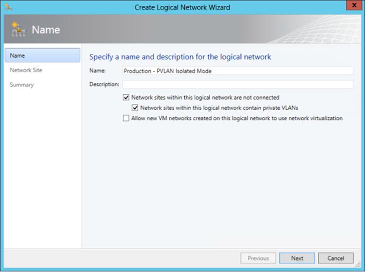
Figure 3.9 Enabling a PVLAN using SCVMM on a new logical network
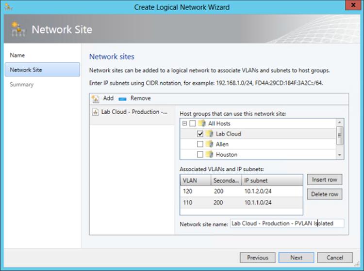
Figure 3.10 Using SCVMM to create multiple isolated PVLANs that use the same secondary VLAN ID
Here are the same PowerShell commands for SCVMM to create the isolated PVLAN configuration that matches the configuration previously performed using the SCVMM graphical interface:
$logicalNetwork = New-SCLogicalNetwork -Name "Production - PVLAN Isolated Mode" ´
-LogicalNetworkDefinitionIsolation $true -EnableNetworkVirtualization $false ´
-UseGRE $false -IsPVLAN $true
$allHostGroups = @()
$allHostGroups += Get-SCVMHostGroup -ID "<GUID>"
$allSubnetVlan = @()
$allSubnetVlan += New-SCSubnetVLan -Subnet "10.1.2.0/24" -VLanID 120 ´
-SecondaryVLanID 200
$allSubnetVlan += New-SCSubnetVLan -Subnet "10.1.1.0/24" -VLanID 110 ´
-SecondaryVLanID 200
New-SCLogicalNetworkDefinition -Name "Lab Cloud - Production - PVLAN Isolated" ´
-LogicalNetwork $logicalNetwork -VMHostGroup $allHostGroups ´
-SubnetVLan $allSubnetVlan -RunAsynchronously
It's very important with PVLAN that all the physical switch ports are configured correctly for the VLANs used as part of the PVLAN configuration or traffic will not flow between hosts correctly. While VLANs are used heavily in many environments, most organizations won't use PVLANs that are aimed at specific scenarios where there is a requirement to have large numbers of hosts/virtual machines that cannot talk to each other. The good news is they are all supported with Hyper-V.
How SCVMM Simplifies Networking with Hyper-V
While SCVMM will be covered in detail later in the book, I've already mentioned its use a number of times in this chapter and I'm about to discuss it a lot more as it moves from being an optional management technology to being the only practical way to implement some technologies. I want to discuss some fundamental SCVMM logical components and how to quickly get up and running with them, including deploying some of the components we've already covered in this chapter the “SCVMM way.”
When you consider what configuration was performed with Hyper-V, it really consisted of creating a virtual switch that was tied to a physical network adapter and how what we named the virtual switch could indicate what it would be used for. However, if that switch connected to an adapter that connected to a switch port that supported different VLANs for different networks, then there was no way to convey that and manage it effectively. Also, there was no concept of separating the network seen by the virtual machines from that defined on the Hyper-V server. Additionally, on each Hyper-V server the virtual switch configuration and any extensions were manually configured. Things get a lot more complicated when virtual switches are used for multiple virtual network adapters on the management operating system, as you'll see when we look at a more converged network infrastructure (and this will be covered in detail later this chapter).
SCVMM introduces quite a few new concepts and constructs that initially may seem a little overwhelming, but they are fundamentally designed to let you model your physical networks, your switch, and your network configurations on the Hyper-V hosts and then model a separate abstracted set of definitions for networks available to virtual machines. These constructs can broadly be divided into those that model connectivity and those that model capability.
I want to build these constructs out and then walk through a configuration for a new deployment. One key point is to ideally perform all your configuration through SCVMM for your Hyper-V host. Install the Hyper-V role with no virtual switches and do nothing else. Don't create virtual switches, don't create NIC teams, don't start creating virtual machines. The best experience is to define the configuration in SCVMM and let SCVMM perform all the configuration on the hosts.
One very important point for networking—whether for physical hosts, for virtualization with Hyper-V, or using SCVMM—is proper planning and design and understanding your physical network topology and your actual requirements and then translating this to your virtual network infrastructure. Why this gets emphasized with SCVMM is that SCVMM networking components will force you to do this planning because you need to model your network within SCVMM using its various networking architectural components to achieve desired results.
1. Discovery. Understand the network requirements of your datacenter and your virtual environments. This may require asking questions of the network teams and the business units to find out what types of isolation are required, what address spaces will be used, and what types of networks exist and need to be leveraged. Do certain types of traffic require guaranteed bandwidth, which would dictate the use of separate networks or use Quality of Service (QoS) technologies?
2. Design. Take the information you have discovered and translate it to SCVMM architectural components. Consider any changes to process as part of virtual environments. This may be an iterative process because physical infrastructure such as hardware switches may limit some options and the design for the virtual network solution may need to be modified to match capabilities of physical infrastructure.
3. Deployment. Configure SCVMM with a networking design and deploy the configuration to hosts, virtual machines, and clouds.
SCVMM Networking Architecture
The first architectural component for SCVMM is the logical network, which helps model your physical network infrastructure and connectivity in SCVMM. Consider your virtualization environment and the networks the hosts and the virtual machines will need to connect to. In most datacenters, at a minimum you would see something like Figure 3.11.
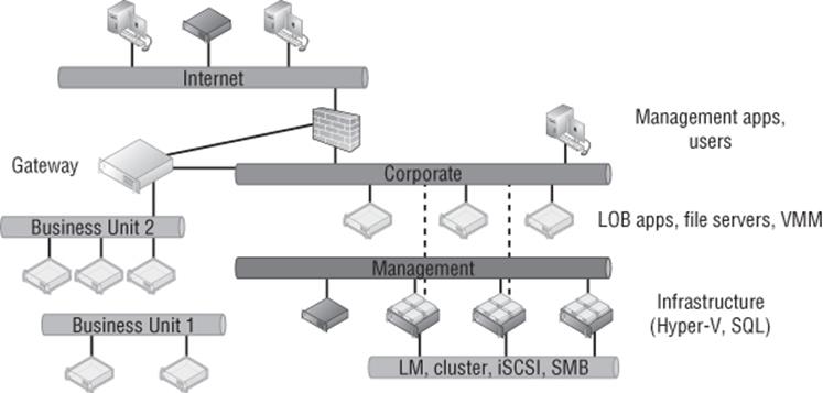
Figure 3.11 Common networks seen in a datacenter with virtualization
In this common datacenter, the different types of networks have different connectivity, different capabilities, and different routing available. The networks may require isolation from each other using various technologies, which is explained in more detail later. Remember, these are just examples. Some datacenters will have many more. Here are the different types of networks you could have:
1. The Internet You may have customers or users that access the network via the Internet and connect to the Internet through various routes, so systems with Internet connectivity will likely need to be modeled as a separate network.
2. Corporate This is usually the primary network in your company where users exist and will connect to the various services offered, such as line of business (LOB) applications, file servers, domain controllers, and more. Additionally, administrators may connect to certain management systems via systems available on the corporate network, such as your VMM server. The VMM environment will need to model the corporate environment so virtual machines can be given connectivity to the corporate environment to offer services.
3. Management Infrastructure servers typically are connected on a separate management network that is not accessible to regular users and may not even be routable from the corporate network.
4. Special Networks Certain types of servers require their own special types of communications, such as those required for cluster communications, live migrations, iSCSI, and SMB storage traffic. These networks are rarely routable and may even be separate, isolated switches to ensure desired connectivity and low latencies or they may use separate VLANs. Some organizations also leverage a separate network for backup purposes.
5. Business Units/Tenants/Labs Separate networks may be required to isolate different workloads, such as different business units, different tenants (if you are a hoster), and lab/test environments. Isolation can be via various means, such as VLANs, PVLANs, or network virtualization. These networks may require connectivity out to the Internet, to other physical locations (common in hoster scenarios where a client runs some services on the hoster infrastructure but needs to communicate to the client's own datacenter), or even to the corporate network, which would be via some kind of gateway device. In Figure 3.11, Business Unit 2 requires connectivity out of its isolated network, while Business Unit 1 is completely isolated with no connectivity outside of its own network.
Each of these different types of networks would be modeled as logical networks in SCVMM. Additionally, an organization may have different physical locations/datacenters, and SCVMM allows you to define a logical network and include details of the sites where it exists along with the configuration required at each site, known as a network site. For example, suppose an organization has two locations, Dallas and Houston, and consider just the management network in this example. In Dallas, the management network uses the 10.1.1.0/24 subnet with VLAN 10, while in Houston, the management network uses the 10.1.2.0/24 subnet with VLAN 20. This information can be modeled in SCVMM using network sites, which are linked to a SCVMM host group and contained within a logical network. This enables SCVMM to assign not just the correct IP address to virtual machines based on location and network but also the correct VLAN/PVLAN. This is a key point. The logical network is modeling the physical network, so it's important that your objects match the physical topology, such as correct IP and VLAN configuration.
Note that a network Site in a logical network does not have to reflect an actual physical location but rather a specific set of network configurations. For example, suppose I had a management network that used two physical switches and each switch used a different VLAN and IP subnet. I would create a single logical network for my management network and then a separate site for each of the different network configurations, one for each VLAN and IP subnet pair.
A network site can be configured with just an IP subnet, just a VLAN, or an IP subnet/VLAN pair. You only need to configure IP subnets for a site if SCVMM will be statically assigning IP addresses to the site. If DHCP is present, then no IP subnet configuration is required. If VLANs are not being used, a VLAN does not need to be configured. If DHCP is used in the network and VLANs are not used, you do not have to create any network sites.
Once the sites are defined within a logical network, IP pools can then be added to the IP address subnet that's defined, which enables SCVMM to actually configure virtual machines with static IP addresses as the virtual machines are deployed. If DHCP is used in the network, there is no need to configure IP pools in SCVMM or even specify the IP subnet as part of the site configuration. DHCP would be leveraged for the IP assignment, but if you don't have DHCP, then creating the IP pool allows SCVMM to handle the IP assignment for you. The IP assignment is achieved by modifying the sysprep answer file with the IP address from the SCVMM IP pool as the virtual machine template is deployed. When the virtual machine is deleted, SCVMM reclaims the IP address into its pool. Even if DHCP is primarily used in the network, if you are using features such as load balancing as part of a service, then SCVMM has to be able to allocate and track that IP address, which will require the configuration of an IP pool. If no IP pool is created for a network site, SCVMM configures any virtual machines to use DHCP for address allocation. Both IPv4 and IPv6 are fully supported by SCVMM (and pretty much any Microsoft technology because a Common Engineering Criteria requirement for all Microsoft solutions is support for IPv6 at the same level as IPv4).
At a high level, this means the logical network models your physical network and allows the subnet and VLANs to be modeled into objects and then scoped to specific sites, which can also include static IP address pools for allocation to resources such as virtual machines and load balancer configurations. This is shown in Figure 3.12, with a management logical network that has two network sites, Dallas and Houston, along with the IP subnet and VLAN used at each location. For Dallas, an IP pool was also created for the network site to enable static IP configuration. Houston would use DHCP because no IP pool was created for the Houston network site within the logical network.
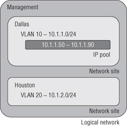
Figure 3.12 High-level view of logical networks
When planning your logical networks, try to stay as simple as possible. There should not be hundreds of logical networks. There should be fewer that contain different network sites that reflect the different network configurations within the type of network that is represented by the logical network. Microsoft has a good blog on designing logical networks at
http://blogs.technet.com/b/scvmm/archive/2013/04/29/logical-networks-part-ii-how-many-logical-networks-do-you-really-need.aspx
The information can really be summarized as follows:
1. Create logical networks to mirror the physical networks that exist.
2. Create logical networks to define the networks that have specific purposes.
3. Identify logical networks that need to be isolated and identify the isolation method.
4. Determine required network sites, VLANs, PVLANs, and IP pools required for each logical network and deploy them.
5. Associate logical networks to host computers.
Logical Switch
Earlier in this chapter, we created a virtual switch, and as part of that configuration there were options available and also the ability to enable certain extensions. While it is possible to perform a configuration on a server-by-server basis manually, this can lead to inconsistencies and inhibits automatic deployment of new Hyper-V hosts. SCVMM has the logical switch component, which acts as the container for all virtual switch settings and ensures a consistent deployment across all servers using the logical switch. The automatic configuration using the logical switch is not only useful at deployment, but SCVMM will continue to track the configuration of the host compared to the logical switch, and if the configuration deviates from that of the logical switch, this deviation will be flagged as noncompliant, and that can then be resolved. This may be important in terms of ensuring compliance enforcement in an environment. If the logical switch is updated (for example, a new extension is added), all the Hyper-V hosts using it will automatically be updated.
Logical switches use port profiles, which are another SCVMM architectural construct of which there are two types: virtual port profiles and uplink port profiles.
The virtual port profile enables settings to be configured that will be applied to actual virtual network adapters attached to virtual machines or created on the management host OS itself. This can include offload settings such as the settings for VMQ, IPsec task offloading, and SR-IOV and security settings such as those for DHCP Guard. It can also include configurations that may not be considered security related, such as guest teaming and QoS settings such as minimum and maximum bandwidth settings. A number of built-in virtual port profiles are provided in SCVMM for common network adapter uses, many of which are actually aimed at virtual network adapters used in the host OS. Figure 3.13 shows the inbox virtual port profiles in addition to the Security Settings page. Once a virtual port profile is used within a logical switch and the logical switch is deployed to a host, if the virtual port profile configuration is changed, the hosts will be flagged as noncompliant because their configuration no longer matches that of the virtual port profile. The administrator can easily remediate the servers to apply the updated configuration.
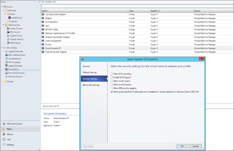
Figure 3.13 Viewing the security settings for the built-in Guest Dynamic IP virtual port profile
An uplink port profile defines the connectivity of the virtual switch to logical networks. You need separate uplink port profiles for each set of hosts that require the same physical connectivity (remember that logical networks define the physical network). Conversely, anytime you need to restrict logical networks to specific hosts in the same location or need custom connectivity, you will require different uplink port profiles. Logical networks can be selected that will be available as part of the uplink port profile and also NIC teaming configuration when used on hosts that will assign multiple network adapters. No inbox uplink port profiles are supplied because their primary purpose models the logical networks that can be connected to and by default there are no logical networks. If a change is made to the uplink port profile definition (for example, adding a new VLAN that is available), SCVMM will automatically update all the virtual switches on the Hyper-V hosts that use the uplink port profile via a logical switch with the new VLAN availability or any other settings within the uplink port profile.
When you put all these components together, it does require some additional upfront work, but the long-term deployment and manageability of the environment becomes much simpler and can help identify misconfigurations or where there are actual problems in network connectivity.
The logical switch is a Live Migration boundary for SCVMM's placement logic. Note that a logical switch can be deployed to many hosts, it can stretch clusters, and so on. However, SCVMM needs to ensure that the same capabilities and connectivity are available when virtual machines are moved between hosts, and so the SCVMM placement logic will not allow live migration to hosts using a different logical switch. If you had a scenario where you required different logical switches in the environment (for example, if you required different extension configurations), then a live migration would not be possible and may be a reason for those hosts to not use the logical switch and instead perform the switch configuration directly on the Hyper-V hosts; this type of switch is known as a standard switch. Standard switches are fully supported within SCVMM, and their deployment and configuration will be via Hyper-V Manager or with SCVMM. If you have an existing Hyper-V server with virtual switches defined that will be standard switches in SCVMM, there is no way to convert them to logical switches. The best option is to delete the standard switches and then re-create the switches as logical switches via SCVMM. To delete the standard switches, you would need to evacuate the host of virtual machines, which typically means you have a cluster. However, with Windows Server 2012, you can also move virtual machines with no downtime using Shared Nothing Live Migration between any Hyper-V hosts provided they have a 1 Gbps network connection.
VM Networks
While the logical network provides the modeling of the networks available in the environment and the desired isolation, the goal for virtualization is to separate and abstract these logical networks from the actual virtual machines. This abstraction is achieved through the use of VM networks, which is another networking architectural component in SCVMM. Through the use of VM networks, the virtual machines have no idea of the underlying technology used by the logical networks, for example, if VLANs are used on the network fabric. Virtual machine virtual network adapters can only be connected to a VM network. When Network Virtualization is used, the Customer Address (CA) space is defined as part of the VM network, allowing specific VM subnets to be created as needed within the VM network.
There may be some scenarios where the isolation provided by VM networks is not actually required—for example, where direct access to the infrastructure is required, such as if your SCVMM server is actually running in a virtual machine, or where the network is used for cluster communications. It is actually possible to create a no isolation pass-through VM network that directly passes communication through to the logical network. The VM network is present only because a virtual machine network adapter needs to connect to a VM network. If a logical network has multiple sites defined, then when a virtual machine is deployed, it will automatically pick the correct IP subnet and VLAN configuration at deployment time based on the location to which it's being deployed. Users of self-service-type portals are exposed to VM networks but not the details of the underlying logical networks.
Port Classifications
Port classifications are assigned to virtual machines that are containers for port profile settings. The benefit of the port classification is that it acts a layer of abstraction from the port profiles assigned to logical switches, which allows a port classification to be assigned to a virtual machine template. The actual port profile used depends on the logical switch the VM is using when deployed. Think of port classifications as being similar to storage classifications; you may create a gold storage classification that uses a top-of-the-line SAN and a bronze storage classification that uses a much lower tier of storage. I may create a port classification of High Bandwidth and one of Low Bandwidth. A number of port classifications are included in-box that correlate to the included virtual port profiles. Port classifications are linked to virtual port profiles as part of the logical switch creation process. Like VM networks, port classifications are exposed to users via self-service portals and not the underlying port profiles.
Microsoft Resource
Microsoft has a great poster available that details all the key networking constructs available. If possible, download this poster, get it printed, and put it up on your wall, or if you have a large monitor, set it as your background. The poster can be downloaded from
www.microsoft.com/en-us/download/details.aspx?id=37137
Deploying Networking with SCVMM 2012 R2
For this part of the chapter, I will assume SCVMM 2012 R2 is up and running in your environment. I cover implementing SCVMM 2012 R2 in Chapter 6, “Maintaining Your Hyper-V Environment,” so if you want to follow along, you may want to jump to Chapter 6 to get a basic deployment in place. The good news is that networking is one of the first components that needs to be configured with SCVMM, so once you have SCVMM deployed and you have created some host groups (which are collections of hosts), you will be ready to follow this next set of steps. Figure 3.14 gives a high-level view of the steps that will be performed.
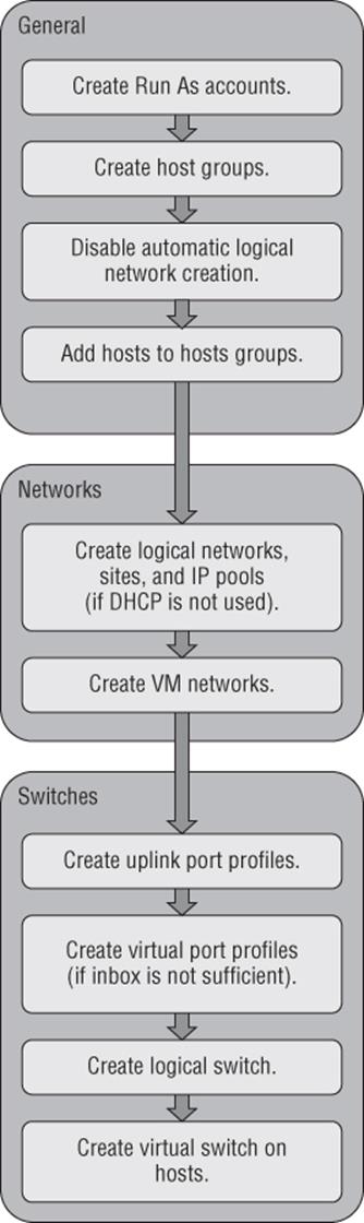
Figure 3.14 The steps for SCVMM network configuration
Disable Automatic Logical Network Creation
The very first action related to networking in SCVMM 2012 R2 is to disable the automatic creation of logical networks. This may seem strange that our first configuration is to disable functionality, but it will help ensure your SCVMM modeling consistency. With automatic logical network creation enabled, when a Hyper-V host that already has a virtual switch defined is added to SCVMM, a logical network will automatically be created in SCVMM if SCVMM does not find a match for an existing logical network based on the first DNS suffix label for the network adapter network (which is the default behavior). For example, if the DNS suffix for a network connection was lab.savilltech.net, then a logical network named lab would be used, and if not found, would automatically be created. This automatic creation of logical networks may be fine in a test environment, but in production, where you have done detailed planning for your logical networks and deployed accordingly, it is very unlikely that the automatic creation of logical networks based on DNS suffix labels would be desirable. Therefore, disable this automatic logical network creation as follows:
1. Open Virtual Machine Manager.
2. Open the Settings workspace.
3. Select the General navigation node.
4. Double-click Network Settings in the details pane.
5. In the Network Settings dialog, uncheck the Create Logical Networks Automatically option as shown in Figure 3.15 and click OK. Notice also in this dialog that it is possible to change the logical network matching behavior to a scheme that may better suit your naming conventions and design.
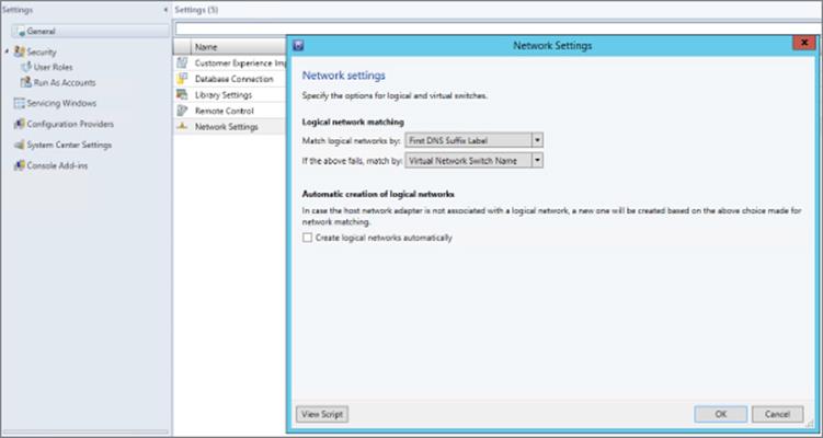
Figure 3.15 Disabling the automatic creation of logical networks in SCVMM 2012 R2
Those of you who used SCVMM 2012 SP1 will notice that the option to also automatically create virtual switches (VM networks) has been removed. The automatic creation of virtual switches, which virtual machines use to connect, actually caused a lot of confusion, so it was removed in R2. At this point you can safely add Hyper-V hosts to the SCVMM environment without them automatically creating logical networks you don't want in the environment.
Creating Logical Networks
In this environment I have three networks available that I will model as logical networks. However, they are all separate VLANs on the same physical network that will be controlled by setting the VLAN ID on the virtual network adapter. The physical ports on the switch have been configured to allow all the various VLANs that can be configured (similar to a trunk port):
· Corporate network. The main address space used by my organization, which on my switches uses VLAN 10 in all locations.
· Lab network. The network used for a number of separate lab environments that each have their own IP subnet and VLAN.
· Network virtualization network. Will be used in the future when network virtualization is explored
The steps to create a logical network are detailed here:
1. Open Virtual Machine Manager.
2. Open the Fabric workspace.
3. Select the Networking ⇒ Logical Networks navigation node.
4. Click the Create Logical Network button, which launches the Create Logical Network Wizard.
5. As shown in Figure 3.16, a name and description for the logical network is entered along with the type of network. It can be a connected network that allows multiple sites that can communicate with each other and use network virtualization, a VLAN-based independent network, or a PVLAN-based network. Note that when you are creating a network with the One Connected Network option, the option to automatically create a VM network to map to the logical network is available, but in this example I will not use that, so we can manually create it. Because this is the corporate network, I do not intend to use network virtualization. Click Next.
6. The next screen allows configuration of the sites. For corporate, I only need a single site using VLAN 10 because the switch is configured to allow VLAN 10 through to the corporate network. Click the Add button to add a site and then click Insert Row to add VLAN/IP details for the site. The actual IP space is all configured by corporate DHCP servers in this example, so I will actually leave the IP subnet blank, which tells SCVMM to just configure the VM for DHCP.
If the network does not use VLANs, then set the VLAN ID to 0, which tells SCVMM that VLANs are not to be configured. By default, sites are given the name <Logical Network>_<number>, but you should rename this to something more useful. For example, as shown in Figure 3.17, I am renaming it Corp Trunk.
For each site, select the host group that contains hosts in that site. Because this can be used in all locations, I select the All Hosts group. Click Next.
7. The Summary screen will be displayed. It includes a View Script button that when clicked will show the PowerShell code that can be used to automate the creation. This can be useful when you are creating large numbers of logical networks, or more likely, large numbers of sites. Click Finish to create the logical network.
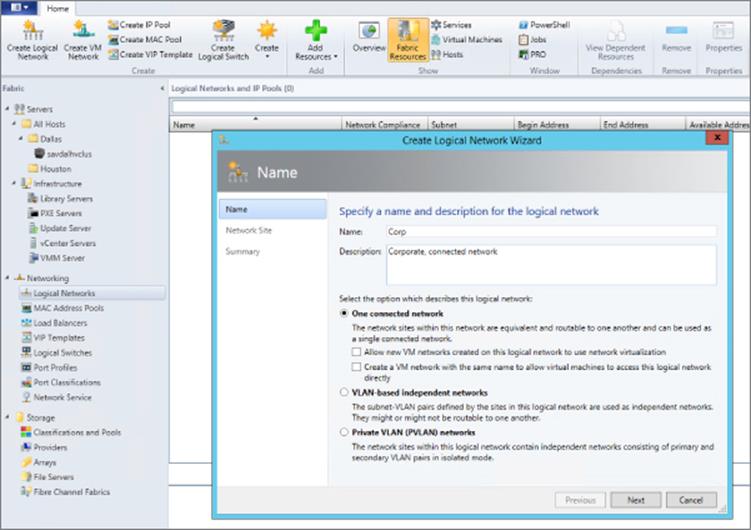
Figure 3.16 Creating a logical network that represents a connected collection of sites
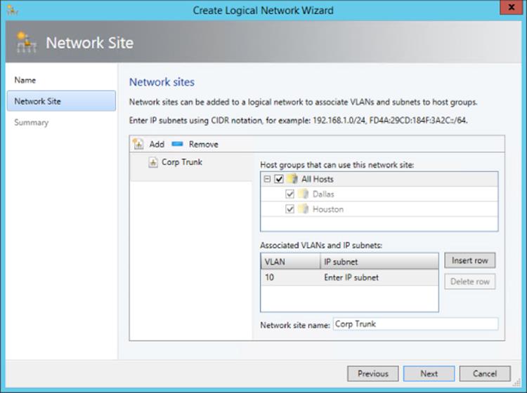
Figure 3.17 Adding a single site to a logical network
Here is the PowerShell code used to create my corporate logical network:
$logicalNetwork = New-SCLogicalNetwork -Name "Corp" ´-LogicalNetworkDefinitionIsolation $false -EnableNetworkVirtualization $false ´ -UseGRE $false -IsPVLAN $false -Description "Corporate, connected network"
$allHostGroups = @()
$allHostGroups += Get-SCVMHostGroup -ID "0e3ba228-a059-46be-aa41-2f5cf0f4b96e"
$allSubnetVlan = @()
$allSubnetVlan += New-SCSubnetVLan -VLanID 10
New-SCLogicalNetworkDefinition -Name "Corp Trunk" ´
-LogicalNetwork $logicalNetwork ´ -VMHostGroup $allHostGroups -SubnetVLan $allSubnetVlan -RunAsynchronously
The next network I would create would be my set of lab networks. In this case I will select the VLAN-based independent networks type, and I will create a separate site for each of the VLAN/IP subnet pairs, which represent separate lab environments as shown inFigure 3.18. I'm creating only two of the VLANs in this example because performing this using the graphical tools is actually very slow. My lab environments are all based in Dallas, so only the Dallas host group is selected. Because the sites in this logical network have IP subnets defined, I would also create an IP pool for each site as in the next set of steps. You will notice most of these settings are similar to those configured for a DHCP scope because essentially SCVMM is performing a similar role; it just uses a different mechanism to assign the actual IP address. All of the details are those that will be configured on the virtual machines that get IP addresses from the IP pool.
1. Click the Create IP Pool button or right-click on the logical network and select the Create IP Pool context menu action.
2. Enter a name and description and select the logical network the IP pool is for from the drop-down list.
3. The next screen, as shown in Figure 3.19, allows you to use an existing network site or create a new one. Choose to use an existing one and then click Next.
4. The IP Address Range page allows configuration of the IP address range that SCVMM will manage and allocate to resources such as virtual machines and load balancers. Within the range, specific addresses can be configured as reserved for other purposes or for use by load balancer virtual IPs (VIPs) that SCVMM can allocate. In Figure 3.20, you can see that I have reserved 5 IP addresses from the range for use by load balancer VIPs. Fill in the fields and click Next.
5. Click the Insert button and enter the gateway IP address. Then click Next.
6. Configure the DNS servers, DNS suffix, and additional DNS suffixes to append and then click Next.
7. Enter the WINS server details if used and click Next.
8. On the Summary screen, confirm the configuration, click the View Script button to see the PowerShell that will be used, and then click Finish to create the IP pool.
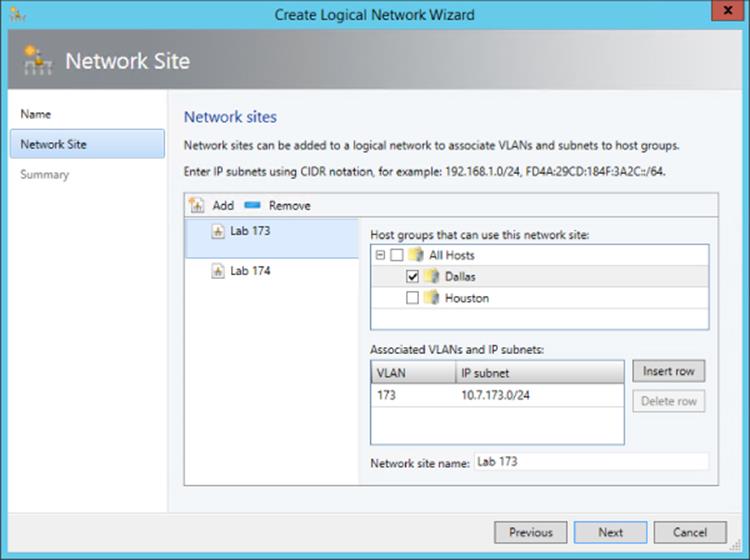
Figure 3.18 Creating a VLAN-based logical network
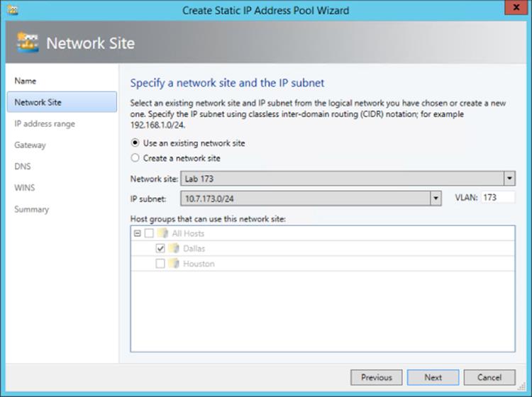
Figure 3.19 Choose the site for a new IP pool or create a new one.
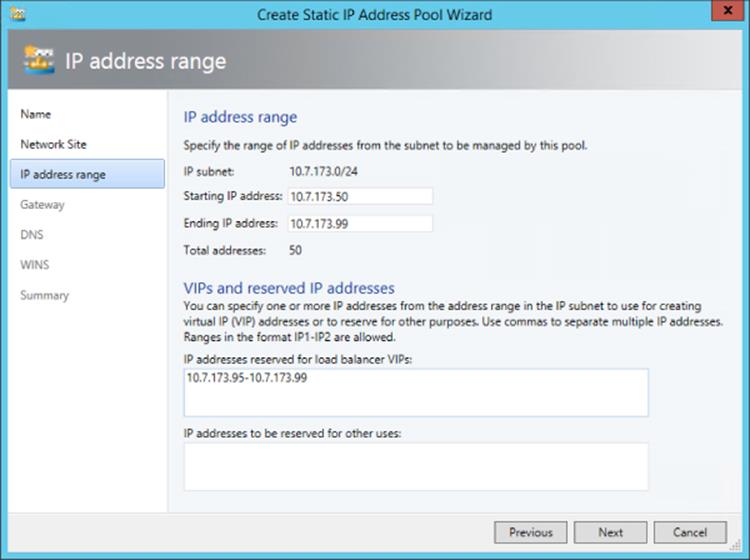
Figure 3.20 Configuring the IP address range for the IP pool
Finally, I will create my Hyper-V network virtualization logical network, which will support network virtualization and be configured with an IP pool that will be used for the provider space for the Hyper-V hosts. This will follow the same process as the other networks, except this time I will select the One Connected Network option and the option “Allow new VM networks created on this logical network to use network virtualization.” A network site is created and a VLAN is configured if needed along with an IP subnet (this must be set), and this will purely be used so that the Hyper-V hosts that are hosting virtual machines that are participating in network virtualization can be allocated their provider address (PA). An IP pool must also be created for the site for the IP address allocation for the PA. No DNS servers are required for the PA network, but if you are using multiple subnets, then a gateway would need to be defined.
Creating Virtual Networks
With logical networks created, the next step is to create the VM networks that virtual machines can actually be connected to. In SCVMM 2012 R2, within the logical networks view, there is a convenient option to create the VM network using the Create VM Network button or by right-clicking on a logical network and selecting Create VM Network. For now we will use the “old-fashioned” way:
1. Open Virtual Machine Manager.
2. Open the VMs And Services workspace (not Fabric, because this is now a construct directly related to virtual machines).
3. Select the VM Networks navigation node.
4. Click the Create VM Network button.
5. Enter a name and description for the VM network, select the logical network, and click Next.
6. Depending on the logical network selected, this may be the end of the configuration. For example, a connected network without network virtualization requires no further configuration. A VLAN type network that is isolated will show an Isolation screen, which allows a specific VLAN (site) to be selected for this specific VM network, or you can select Automatic, which allows SCVMM to automatically select a site based on those available on the logical network. If a network that is enabled for network virtualization is selected, a number of additional configuration pages must be completed to define the configuration for the IP scheme in the virtual network space (CA). I will cover this in detail in the section “Network Virtualization.”
Click Finish to complete the VM Network creation process.
My final configuration is shown in Figure 3.21 for my logical networks and VM networks.
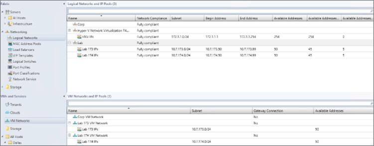
Figure 3.21 The complete logical network and VM network configuration
So far we have done a lot of configuration but have not modeled our network to SCVMM. Consider my lab environment. I configured 2 of the VLANs to separate the different lab environments, but suppose I have 40 or 80 or 200. This is where PowerShell is invaluable, and I created the script that follows to automate this configuration process.
This script creates a separate site for each VLAN with the appropriate IP subnet and also an IP pool (which in my case was just two addresses that were used for the first 2 machines that were domain controllers because the rest were assigned by DHCP). In my lab, the third octet matches the VLAN ID. This script automatically creates all 40 VLAN sites, which run from 150 to 190, and the appropriate IP pools. You can customize it to meet your own needs, including changing the name of the SCVMM server and also replacing with the logical network that all the sites should be added to (you have to create the logical network in advance, although this could also be added to this script if required). To find the GUID of your logical network, run the command Get-SCLogicalNetwork | ft Name, ID -Auto.
Import-Module virtualmachinemanager
Get-VMMServer -ComputerName scvmm
#Replace this with actual ID of the Logical Network.
#Get-SCLogicalNetwork | ft name, id
$logicalNetwork = Get-SCLogicalNetwork -ID "xxxxxxxx-xxxx-xxxx-xxxx-
xxxxxxxxxxxx"
$startNumber = 150
$endNumber = 190
$vlanID = $startNumber
do
{
$allHostGroups = @()
$allHostGroups += Get-SCVMHostGroup -ID "0e3ba228-a059-46be-aa41-2f5cf0f4b96e"
$allSubnetVlan = @()
$allSubnetVlan += New-SCSubnetVLan -Subnet "10.1.$vlanID.0/24" -VLanID $vlanID
$logicalNetworkDefinition = New-SCLogicalNetworkDefinition -Name "VLAN_$vlanID" ´
-LogicalNetwork $logicalNetwork -VMHostGroup $allHostGroups ´
-SubnetVLan $allSubnetVlan -RunAsynchronously
# Gateways
$allGateways = @()
$allGateways += New-SCDefaultGateway -IPAddress "10.1.$vlanID.1" -Automatic
# DNS servers
$allDnsServer = @("10.1.$vlanID.10", "10.1.$vlanID.11")
# DNS suffixes
$allDnsSuffixes = @()
# WINS servers
$allWinsServers = @()
$NewVLANName = "VLAN_" + $vlanID + "_IP_Pool"
New-SCStaticIPAddressPool -Name $NewVLANName ´
-LogicalNetworkDefinition $logicalNetworkDefinition -Subnet "10.1.$vlanID.0/24" ´
-IPAddressRangeStart "10.1.$vlanID.10" -IPAddressRangeEnd "10.1.$vlanID.11" ´
-DefaultGateway $allGateways -DNSServer $allDnsServer -DNSSuffix "" ´
-DNSSearchSuffix $allDnsSuffixes -RunAsynchronously
#Now create VM Network for each
$vmNetwork = New-SCVMNetwork -Name "Customer_VLAN_$vlanID" ´
-LogicalNetwork $logicalNetwork -IsolationType "VLANNetwork" ´
-Description "VM Network for Customer VLAN $vlanID"
$logicalNetworkDefinition = Get-SCLogicalNetworkDefinition -Name "VLAN_$vlanID"
$subnetVLAN = New-SCSubnetVLan -Subnet "10.7.$vlanID.0/24" -VLanID $vlanID
$VMSubnetName = "Customer_VLAN_" + $vlanID + "_0"
$vmSubnet = New-SCVMSubnet -Name $VMSubnetName ´
-LogicalNetworkDefinition $logicalNetworkDefinition -SubnetVLan $subnetVLAN ´
-VMNetwork $vmNetwork
$vlanID += 1
}
until ($vlanID -gt $endNumber)
Creating the Port Profiles and Logical Switch
Now that the logical networks and VM networks exists, I can create my logical switch, but remember, the logical switch uses the uplink port profiles to identify the connectivity available. I also use virtual port profiles and port classifications. I will use the built-in objects for those, but they are easy to create if required using the Fabric workspace and the Port Profiles and Port Classifications navigation areas. I recommend looking at the existing virtual port profiles and port classifications as the foundation of configuration should you need to create your own. Now is a good time to take a look at the inbox port profiles and port classifications, which you can choose to keep, delete, or even modify to exactly meet your own needs.
The first step is to create the uplink port profiles. Remember, the uplink port profile models the connectivity available for a specific connection from the host, that is, from the network adapter to the switch. If different network adapters have different connectivity to different switches, you will need multiple uplink port profiles. Here are the steps:
1. Open Virtual Machine Manager.
2. Open the Fabric workspace.
3. Select the Networking ⇒ Port Profiles navigation node.
4. Click the Create button drop-down and select Hyper-V Port Profile.
5. Enter a name and description for the new port profile, as shown in Figure 3.22. Select the Uplink Port Profile radio button. You can additionally configure a teaming mode, which is used if the port profile is used on a host where NIC Teaming is required and the settings configured in the port profile will be applied. Because I am connecting all my Hyper-V boxes to ports configured on the switch with multiple VLANs allowed, I only need one uplink port profile that can connect any of the networks. Click Next.
6. Select the network sites (that are part of your logical networks) that can be connected to via this uplink port profile (Figure 3.23). Because all of my networks can, I will select them all and also check the box to enable Hyper-V Network Virtualization. On Windows 2012 Hyper-V hosts, this option enables Network Virtualization in the networking stack on the network adapter, but it does nothing on Windows Server 2012 R2 hosts, which always have Network Virtualization enabled because it's part of the switch. Check the network sites that can be connected via this uplink port profile and click Next.
7. Click Finish to complete the creation of the uplink port profile.
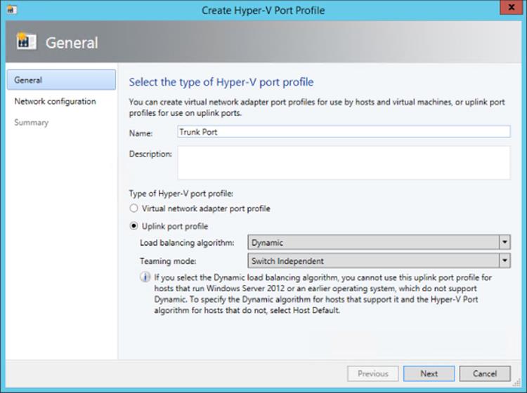
Figure 3.22 Setting the options for a new uplink port profile and NIC Teaming options
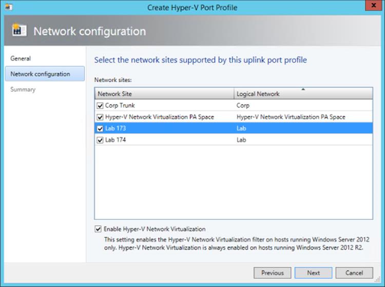
Figure 3.23 Selecting the network sites that can be connected to using the uplink port profile
The final step of modeling is the creation of the actual logical switch, which will then be applied to the Hyper-V hosts. The logical switch will bring all the different components together. Follow these steps:
1. Open Virtual Machine Manager.
2. Open the Fabric workspace.
3. Select the Networking ⇒ Logical Switches navigation node.
4. Click the Create Logical Switch button.
5. The Create Logical Switch Wizard will launch. Read all the text on the introduction page. It confirms all the tasks you should have already performed, such as creating the logical networks, installing extensions, and creating uplink port profiles (aka native port profiles). Click Next.
6. Enter a name and description for the new logical switch. If you wish to use SR-IOV, the Enable Single Root I/O Virtualization (SR-IOV) box must be checked, and this cannot be changed once the switch is created. Click Next.
7. The list of installed virtual switch extensions are displayed and can be selected for deployment as part of the logical switch usage. This can be changed in the future if required. Click Next.
8. The uplink port profiles must be selected. The first option is the uplink mode, which by default is No Uplink Team, but it can be changed to Team. Setting the value to Team tells SCVMM to create a NIC team (using the settings in the uplink port profile) if the logical switch is deployed to a host and multiple network adapters are selected. Click the Add button, select the uplink port profile to be added, and click OK. Multiple uplink port profiles can be added as required. Click Next.
9. The virtual port profiles should now be added to the logical switch. Click the Add button, and in the dialog that appears, click the Browse button to select the port classification (remember, this is the generic classification that is exposed to users of the environment). Then check “Include a virtual network adapter port profile in this virtual port” and select the virtual port profile that corresponds. For example, if I selected the high-bandwidth port classification, then most likely I would select the High Bandwidth Adapter virtual port profile object. Click OK. Repeat to add additional classifications. Select the classification you would like to be the default and click the Set Default button. Click Next.
10.Click Finish to create the logical switch.
Configuring a Hyper-V Host with a Logical Switch
The final step is to now configure Hyper-V hosts with the logical switch, which will trigger SCVMM to actually create virtual switches on the Hyper-V host that matches the configurations defined. It also sets up the environment for virtual machine and service deployments, and all the networking elements will be configured automatically.
In my lab, my Hyper-V hosts have three network adapters that I wish to have teamed to use for my Hyper-V virtual switch. I also have a separate network adapter for management actions such as RDP and file services and another network adapter for cluster and Live Migration operations. I don't use iSCSI or SMB in this environment because it uses Fibre Channel to connect to a SAN. I'm covering this so you understand why I will make the choices I make. However, if you need the virtual switch to use all your network adapters, including your management network adapter, SCVMM can take care of ensuring that you don't lose connectivity, which I will cover in the following walk-through.
1. Open Virtual Machine Manager.
2. Open the VMs And Services workspace.
3. Navigate to your Hyper-V hosts.
4. Right-click on a Hyper-V host and choose Properties.
5. Click the Hardware tab and scroll down to the Network Adapters section. Your network adapters will be shown, and right now they will all be disconnected from a logical network.
6. Click the Virtual Switches tab and click the New Virtual Switch button. The option to create a new logical switch or a new standard switch is displayed. Click the New Logical Switch option.
7. In this walk-through, only one logical switch was created, and that will be selected automatically along with one network adapter. This network adapter can be changed using the drop-down, as can the uplink port profile it uses. Additional network adapters can be added using the Add button if you wish to create a team.
In most environments, the uplink port profile will need to be the same for all network adapters, and SCVMM will actually perform a check and gray out the option to change the uplink port profile for any additional network adapters, as shown in Figure 3.24. There are some third-party forwarder switch extensions that do allow different connectivity for different adapters in a team, which would be detected if configured for the logical switch by SCVMM and the option to set different virtual port profiles was enabled.
8. This step is needed only if virtual network adapters need to be created on the Hyper-V host, such as, for example, in the scenario in which I'm using the network adapter I use for management as part of the new virtual switch. Click the New Virtual Network Adapter button. Enter a name for the new network adapter. There is a check box enabled by default, “This virtual network adapter inherits settings from the physical management adapter,” which tells SCVMM to copy the MAC address and IP configuration from the first adapter in the team into the new virtual network adapter it is creating, which will ensure continued connectivity for the host. Because the MAC address is copied, this would ensure that even if DHCP was used, the same IP address would be assigned. Click the Browse button in the Connectivity section to select the connectivity for the virtual network adapter and a port profile classification. Multiple virtual network adapters can be added as required.
9. Once all configuration is complete, click OK for the configuration to be applied. A warning that connectivity may temporarily be lost during configuration is displayed. Click OK. This would only happen if you are using your management network adapter in the new switch.
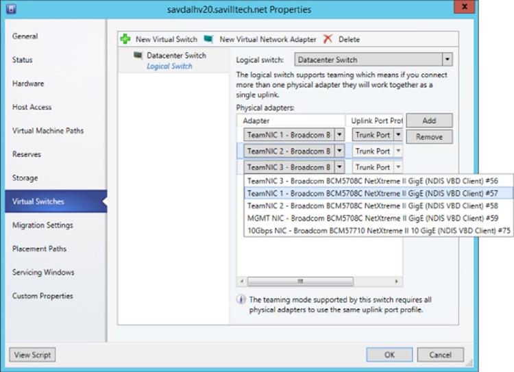
Figure 3.24 Selecting the adapters to be used for the logical switch deployment
The progress of any action performed by SCVMM, known as a job, can be viewed via the Jobs workspace, and as Figure 3.25 shows, my switch deployment completed successfully. On the bottom of the figure, you can see each step that was actually performed. You will notice I actually configured the logical switch on two hosts, which are members of the same cluster, and it's important to have a consistent configuration across any clusters to ensure that no problems occur with connectivity and functionality as virtual machines are moved between hosts. Remember that SCVMM requires hosts to have the same logical switch to be available for placement during live migrations. The eagle-eyed reader may notice that the logical switch creation on savdalhv20.savilltech.net (second line down from the top of Figure 3.25) shows that it completed with information, which was not the case for the savdalhv21.savilltech.net, which I configured second (the top line). The information was as follows:
Information (26844)
Virtual switch (Datacenter Switch) is not highly available because the switch is not available in host (savdalhv21.savilltech.net).
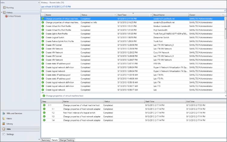
Figure 3.25 Viewing the status of logical switch deployment
SCVMM was telling me that I had deployed a logical switch to a server that was part of a cluster and that because the same logical switch was not available in the other node of the cluster, it was not highly available. This is why I did not get an information message when adding the logical switch to the second node because then the logical switch was available on both nodes.
When connecting to the Hyper-V hosts where I deployed the logical switch, I now see that a new NIC team has been created and a new virtual switch in Hyper-V that matches the configurations of all those SCVMM networking constructs that I defined.
When a virtual machine is created, the VM networks that are available will be listed to choose from based on those available within the logical switch, which were set via the uplink port profile selections.
Looking at all the work that was done, it certainly seems like it was far more than just manually creating a switch in Hyper-V Manager, which can be automated with PowerShell. However, consider having hundreds of Hyper-V hosts, and also realize that now the environment has been fully modeled in SCVMM, allowing for very intricate deployments without the need for users to understand the underlying network fabric or for administrators to search for which IP address and VLAN to use. With the work done upfront, the ongoing management is far easier while also assuring compliance.
Network Virtualization
Previously, I covered VLAN and PVLANs as technologies to provide some isolation between virtual machines and even abstract the connectivity from the physical network to a limited degree. However, the challenge was the scalability limits of VLANs, the narrow scenarios where PVLANs make sense, and the relative complexity and overhead of configuration required on the network equipment where VLANs are used and modified. Even with VLANs, there is not a true abstraction of the virtual network and the physical fabric.
Look at every aspect of the virtual environment. Memory, processor, and storage have all been virtualized very effectively for a virtual machine but not the network. Our goal when we talk about clouds is to pool all our resources together for greater scale and flexibility, but physical networks can impede this seamless pooling. When a virtual machine is attached to a virtual switch, it needs to match the IP scheme used on the underlying network fabric to be able to communicate. I spent a lot of time modeling the network in SCVMM, and once configured, it makes the management of the network much easier, but it also enables a far more powerful feature, network virtualization.
Network Virtualization Overview
Network virtualization separates the address space seen by the virtual machines, the customer address (CA) space, from that used to actually send the packets over the network, the provider address (PA) space, providing abstraction of the network and complete isolation between different virtual networks. Because of this complete isolation of address space, it allows tenants to bring their own IP schemes and subnets to a virtual environment and also allows overlapping of IP subnets between different virtual networks. Additionally, because of this abstraction it's possible for virtual machines to actually move between locations without requiring changes to their IP configuration. This is very important in many scenarios. Hosting companies who want to host many tenants benefit greatly from network virtualization because each tenant is completely isolated from every other tenant with complete IP flexibility. Think about a company hosting Coke and Pepsi. It's important to be able to keep them completely isolated! Organizations who host different business units can also provide complete isolation and, again, flexible IP schemes. Even without the need for flexible IP schemes or complete isolation, a move to network virtualization and what is known as software-defined networking (SDN) removes the complexity of managing physical network infrastructure anytime a change is required that is commonly needed when using existing technologies such as VLANs. Network virtualization also removes the scalability challenges associated with VLANs.
This virtual network capability is enabled through the use of two IP addresses for each virtual machine and a virtual subnet identifier that indicates the virtual network to which a particular virtual machine belongs. The first IP address is the standard IP address that is configured within the virtual machine, the customer address (CA). The second IP address is the IP address the virtual machine actually communicates over the physical network with, known as the provider address (PA). The PA is actually invisible to the virtual machine; the Hyper-V host owns the PA.
This is best explored by an example. In this example, we have a single physical fabric, and running on that fabric are two separate organizations, the red and blue organizations. Each organization has its own IP scheme that can overlap, and the virtual networks can span multiple physical locations. This is shown in Figure 3.26. Each virtual machine that is part of the virtual red or blue networks would have its own customer address, and then a separate provider address would be used to send the actual IP traffic over the physical fabric. The important part is that like other aspects of virtualization, the virtual machines have no knowledge that the network is virtualized. The virtual machines in a virtual network believe they are operating on a physical network available only to them.
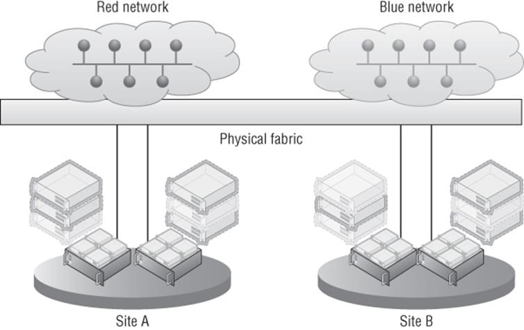
Figure 3.26 High-level overview of network virtualization
Network Virtualization Generic Routing Encapsulation (NVGRE) is used for the network virtualization implementation; it is an extension of GRE, an IETF standard. With NVGRE, the network virtualization works by wrapping the originating packet from the VM, which uses the CA addresses (which are all the virtual machine is aware of), inside a packet that can be routed on the physical network using the PA IP addresses. It also includes the actual virtual subnet, which represents a specific subnet within a virtual network. The virtual subnet is included in the wrapper packet, so each VM does not require its own PA address because the receiving host can identify the targeted VM based on the CA target IP address within the original packet and the virtual subnet ID in the wrapper packet. The virtual subnet ID is actually stored in the GRE key, which is a 24-bit key allowing over 16 million virtual subnets, very different scalability from the 4 thousand limit of VLANs. The only information the Hyper-V host on the originating VM needs to know is which Hyper-V host is running the target VM and can then send the packet over the network. This can be seen in Figure 3.27, where three virtual machines exist in a virtual network and are running across two separate Hyper-V servers. In the figure, CA1 is talking to CA2. However, note in the lookup table on the first Hyper-V server that the PA address for CA2 and CA3 are the same since they run on the same Hyper-V host. The PA address is for each Hyper-V host rather than each virtual machine.
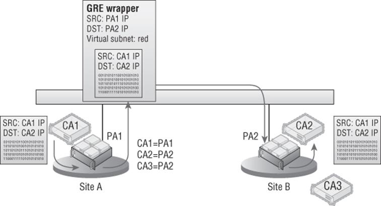
Figure 3.27 High-level overview of network virtualization using NVGRE
The use of a shared PA means that far fewer IP addresses from the provider IP pools are needed, which is good news for IP management and the network infrastructure. When thinking about the actual data going across the wire when using the NVGRE encapsulation, the packet structure would be composed as shown in the following list. As expected, the full Ethernet and IP header and payload from the virtual machine communication is wrapped in an Ethernet and IP header that can be used on the physical network fabric based on the Hyper-V host MAC addresses and PA IP addresses. The full specification for NVGRE can be found at
http://tools.ietf.org/html/draft-sridharan-virtualization-nvgre-01
Note that VLANs can still be used on the physical fabric for the PA and would just be part of the standard packet, completely invisible to the Network Virtualization traffic. The packet structure for NVGRE encapsulation is as follows:
· PA Ethernet MAC source and destination addresses
· PA IP source and destination addresses
· Virtual subnet ID (VSID)
· VM Ethernet MAC source and destination addresses
· CA IP source and destination addresses
· Original IP payload
There is a potential downside to using NVGRE that I at least want to make you aware of. Because the original packet is being wrapped inside the NVGRE packet, any kind of NIC offloading such as IPsec processing in the network adapter will break because the offloads won't understand the new packet format. The good news is that many of the major hardware manufacturers are looking to add support for NVGRE to all their network equipment, which will once again enable offloading even when NVGRE is used. Additionally, even without offloading, typically there is not a significant performance degradation until very high-bandwidth (over 5 Gbps) scenarios are reached.
Virtualization policies are used between all the Hyper-V hosts that participate in a specific virtual network to enable the routing of the CA across the physical fabric and to track the CA-to-PA mapping. The virtualization policies can also define which virtual networks are allowed to communicate with other virtual networks. The configuration of the virtualization policies can be accomplished via PowerShell, which is the direction for all things Windows Server. However, trying to manually manage network virtualization using PowerShell is not practical. The challenge in using the native PowerShell commands is the synchronization and orchestration of the virtual network configuration across all Hyper-V hosts that participate in a specific virtual network. The supported solution, and really the only practical way, is to use the virtualization management solution to manage the virtual networks and not to do it manually using PowerShell, which means use System Center Virtual Machine Manager.
1. What Happened to IP Rewrite?
If you looked at network virtualization for Windows Server 2012 early on, you would have seen two types of network virtualization technology: NVGRE and IP rewrite. IP rewrite was originally introduced at the same time NVGRE was introduced because there was a concern that the NVGRE encapsulation would introduce too much overhead. IP rewrite worked by rewriting the IP information of the packet as it was sent over the wire to use the PA space instead of the CA space, which meant a regular packet was being sent over the network instead of an encapsulated packet and therefore all existing offloads continue to function. When the packet reached the destination Hyper-V host, the IP address was rewritten again back to the CA space. This meant that there had to be a PA for every CA used, which was a lot of IP addresses from the PA space. The reality was that customers found the different technologies confusing. In addition, after testing, it was found that even without NVGRE optimized hardware, there was not the performance penalty expected by NVGRE until workloads started approaching 5 Gbps for a single VM, which would actually be a fairly isolated, extreme instance in most environments. Only at this time did NVGRE support in the networking equipment to enable offloads become a factor. For this reason, IP rewrite was actually deprecated in Windows Server 2012 and has been removed in SCVMM 2012 R2.
Referring back to the different planes required for network virtualization to work will help you understand the criticality of SCVMM. Whereas SCVMM can be considered “not essential” for some areas of Hyper-V where the end result could still be achieved, albeit with far more work and customization, this is really not the case for network virtualization that needs SCVMM. These planes are shown in Figure 3.28:
1. Data Plane Packets are actually encapsulated and decapsulated for communication over the wire on the data plane. This is implemented by Hyper-V and leverages NVGRE for the encapsulation.
2. Control Plane Controls how configuration is propagated to the networking equipment and the Hyper-V servers. This is handled very efficiently by Hyper-V and SCVMM by actually using SCVMM as a central policy store, which is then used by the Hyper-V servers, avoiding large amounts of network “chatter” related to control traffic. This provides a scalable solution, and as changes occur, such as to which host a virtual machine is hosted on, SCVMM, as that central policy store, can notify all Hyper-V hosts affected in real-time.
3. Management Plane The network is actually configured and managed on the management plane. This is SCVMM using its management tool and SCVMM PowerShell cmdlets.
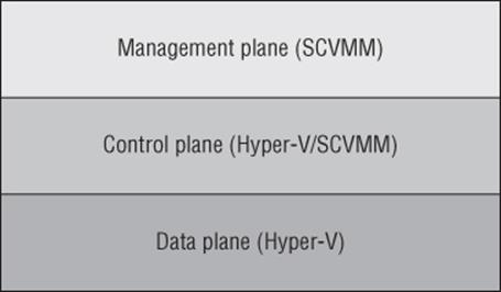
Figure 3.28 The three planes that enable network virtualization
So far when talking about network virtualization, I have focused on the virtual subnet ID (VSID). However, strictly speaking, the VSID is not actually the isolation boundary. The true boundary of a virtual network is the routing domain, which is the boundary of the routing policies that control the communication and therefore the isolation boundary. Think of the routing domain as the container that then contains virtual subnets, which can all communicate with each other. You may actually see three different names used, but they all mean a virtual network:
· Virtual network: The official nomenclature
· Routing domain: Name used when managing with PowerShell
· VM network: Name used within SCVMM
For efficiency of communications, you may still wish to define different virtual subnets for different locations or requirements within a virtual network (even though you don't have to). A virtual subnet, like a physical subnet, acts as a broadcast boundary. Later on I'll discuss using gateways to enable communication between different virtual networks and to the Internet or physical networks.
No separate gateway technology is required for different virtual subnets within a single virtual network to communicate. The Hyper-V Network Virtualization component within the Hyper-V switch takes care of routing between virtual subnets within a virtual network. The Hyper-V Network Virtualization filter that runs within the Hyper-V virtual switch always provides a default gateway for each virtual subnet, which is always the .1 address and is commonly referred to as the .1 gateway. For example, if the virtual subnet was 10.1.1.0/24, then the gateway address would be 10.1.1.1. The gateway will route traffic between the different virtual subnets within the same virtual network, so it's actually acting as a router.
Windows 2012 R2 uses a new intelligent unicast replication if there are CA broadcasts/multicasts on the network. What this means is that a VM sends a broadcast to its virtual subnet, then Hyper-V will actually only send this broadcast once to each Hyper-V host that hosts VMs on that virtual subnet. Then the target host sends the packet to each virtual machine. Only IP broadcast and multicast is supported, such as ARP, Duplicate Address Detection, and Neighbor Unreachability Detection.
Another benefit to network virtualization is that the networking visible to the virtual machines, which is now provided using software, can now be managed by the virtualization administrators and even the virtualization tenants instead of having to involve the networking team, who can focus on the physical network infrastructure.
Implementing Network Virtualization
In many areas of this book I talk about natively performing configurations using Hyper-V capabilities and also how to perform them with SCVMM. For network virtualization, I will only show how by using SCVMM. Hopefully I've already made it clear that trying to implement network virtualization manually using PowerShell may work if you use complex PowerShell for a couple of hosts where you don't move virtual machines, but in any real world or even a lab environment, you have to use a management solution, which in this case is SCVMM. A key point is to make sure any virtual machine migrations are performed using SCVMM, which enables policies to be updated instantly. If a migration was performed using Hyper-V Manager or any non-SCVMM method, it will take time for SCVMM to notice that the virtual machine has moved and update policies accordingly, which will mean that routing of network virtualization traffic would be affected adversely until SCVMM detected the virtual machine move.
Virtual networks can be created only on logical networks that were enabled for network virtualization, and as long as you select a virtualization-enabled logical network, the process to create a virtual network with SCVMM is simple:
1. Open Virtual Machine Manager.
2. Open the VMs and Services workspace (not Fabric, because this is now a construct directly related to virtual machines).
3. Select the VM Networks navigation node.
4. Click the Create VM Network button.
5. Enter a name and a description for the VM network, select the logical network that was enabled for network virtualization, and click Next.
6. Select Isolate Using Hyper-V Network Virtualization and by default IPv4 will be used for the VM and logical networks. Click Next.
7. You will now create VM subnets, which are the IP addresses used within the virtual networks. Click the Add button and then enter a name and subnet in the CIDR syntax: <IP subnet>/<number of bits to use for subnet mask>, as shown in Figure 3.29. Click Next.
8. If gateways are configured in SCVMM, a gateway can be selected, but for now click Next because none are available.
9. Click Finish to create the new VM network and VM subnets.
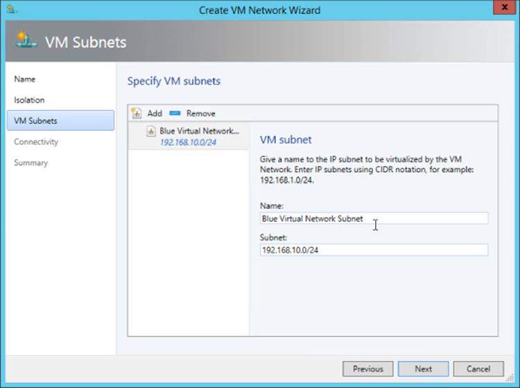
Figure 3.29 Creating a VM subnet within a new VM network
Once the VM network is created, you must create IP pools for each of the VM subnets that were defined. Right-click the VM network and select Create IP Pool; then follow the same process you used to create IP pools for a logical network site, but select a VM subnet instead of a logical network site. Make sure an IP pool is created for every VM subnet because these IP pools are used for the IP address assignment for virtual machines connected to the virtual network.
The next step is to actually connect virtual machines to a VM network, and this is done through the properties of a virtual machine, by selecting the Hardware Configuration tab. Select the network adapter to be connected, select the Connected To A VM Network button. Click the Browse button to select the specific VM network (for example, Blue Virtual Network), and then select the VM subnet, as shown in Figure 3.30. Click OK to make the change take effect.
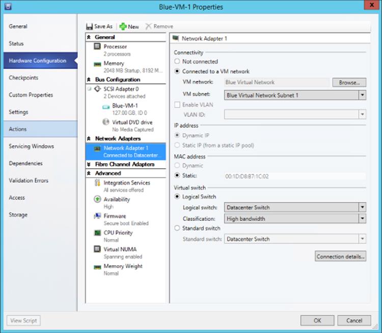
Figure 3.30 Connecting a virtual machine network adapter to a VM network
At this point network virtualization is configured and being used. If the ping firewall exception is enabled within the virtual machines (the firewall exception is File And Printer Sharing [Echo Request - ICMPv4-IN]), then virtual machines within the same VM network will be able to ping each other and communicate using whatever protocols have been enabled. Different virtual networks will not be able to communicate, nor can the virtual networks communicate with anything outside of their own virtual network.
Useful Network Virtualization Commands
If you're like me, you'll agree that it's great that SCVMM has really made network virtualization simple and it all just works, but when it comes to troubleshooting and just understanding technologies a little better, it's good to “peek behind the curtain” at what is actually happening on the Hyper-V hosts that are hosting virtual machines that are part of virtual networks, which is what I want to do in this part of the book.
Remember that as part of the logical network configuration for the network that is network virtualization enabled, an IP pool that would be used for the provider address space was created. When a Hyper-V host starts hosting virtual machines that are part of a virtualized network, it has an additional IP address in the provider space for each virtual network that is used by virtual machines that it hosts. You may expect to see these additional IP addresses when running ipconfig (or in PowerShell, Get-NetIPAdress). However, the PA IP addresses will not be shown. Instead, to see the IP addresses for a Hyper-V host from the PA, you must run the PowerShell command Get-NetVirtualizationProviderAddress. Here is the output shown on a host that is hosting virtual machines on two different virtual networks:
PS C:\Users\administrator.SAVILLTECH> Get-NetVirtualizationProviderAddress
ProviderAddress : 172.1.1.6
InterfaceIndex : 44
PrefixLength : 0
VlanID : 173
AddressState : Preferred
MACAddress : 001dd8b71c08
ManagedByCluster : False
ProviderAddress : 172.1.1.3
InterfaceIndex : 44
PrefixLength : 0
VlanID : 173
AddressState : Preferred
MACAddress : 001dd8b71c03
ManagedByCluster : False
I previously mentioned the lookup table, or routing table, that is used by the Hyper-V hosts to know which Hyper-V host should be communicated with when a virtual machine on a virtual network needs to talk to another virtual machine with a specific CA IP address on the same virtual network. This routing table is maintained by SCVMM and is populated to the Hyper-V hosts, and only the relevant records for a specific host are populated. For example, if two virtual networks exist, blue and red, and one host only hosts virtual machines connected to the blue virtual network, then none of the policies (routing records) related to the red virtual network would be populated on the host. To look at the lookup records for a host, use the Get-NetVirtualizationLookupRecord command, which will show the customer address (the IP address within the VM), the virtual subnet ID (the virtual subnet), and then the actual provider address (plus details such as the VM name). The following is the content of my environment that hosts four virtual machines that are connected to three different virtual subnets within two virtual networks. I've selected to show only certain fields in the output for readability:
PS C:\> Get-NetVirtualizationLookupRecord | Sort-Object VMName | Format-Table CustomerAddress,VirtualSubnetID,ProviderAddress,VMName -AutoSize
CustomerAddress VirtualSubnetID ProviderAddress VMName
--------------- --------------- --------------- ------
192.168.10.4 6864375 172.1.1.3 Blue-VM-1
192.168.10.5 6864375 172.1.1.4 Blue-VM-2
192.168.11.2 6836310 172.1.1.3 Blue-VM-3
192.0.2.253 16200119 172.1.1.6 DHCPExt.sys
192.0.2.253 6864375 172.1.1.3 DHCPExt.sys
192.0.2.253 6836310 172.1.1.3 DHCPExt.sys
192.168.10.1 16200119 1.1.1.1 GW
192.168.11.1 6836310 1.1.1.1 GW
192.168.10.1 6864375 1.1.1.1 GW
192.168.10.2 16200119 172.1.1.6 Red-VM-1
As can be seen, there are the records you would expect for each of the virtual machines, and notice that the provider address is the same for Blue-VM-1 and Blue-VM-3, because both are running on the same Hyper-V host. Additionally, for each virtual subnet there is a GW (gateway) entry, which is facilitated by the Hyper-V virtual switch to send traffic between virtual subnets (that are part of the same virtual network) and also an entry for the SCVMM DHCP virtual switch extension. If I run the same command on my other Hyper-V host, which hosts only a single VM that is connected to the blue virtual network, I see a simpler lookup table, as shown in the following output. It does not see records for the red virtual network because it does not need to know. That's because it hosts no VMs connected to the red virtual network, and it has only a single GW and DHCP virtual switch extension because it only hosts a VM connected to a single virtual subnet.
PS C:\> Get-NetVirtualizationLookupRecord | Sort-Object VMName | ´
Format-Table CustomerAddress,VirtualSubnetID,ProviderAddress,VMName -AutoSize
CustomerAddress VirtualSubnetID ProviderAddress VMName
--------------- --------------- --------------- ------
192.168.10.4 6864375 172.1.1.3 Blue-VM-1
192.168.10.5 6864375 172.1.1.4 Blue-VM-2
192.168.11.2 6836310 172.1.1.3 Blue-VM-3
192.0.2.253 6864375 172.1.1.4 DHCPExt.sys
192.168.10.1 6864375 1.1.1.1 GW
To make this easier to understand, I created a picture to show the actual virtual machines and hosts that are being examined with these commands, which can be seen in Figure 3.31. Hopefully this will help make the output from the above commands clearer.
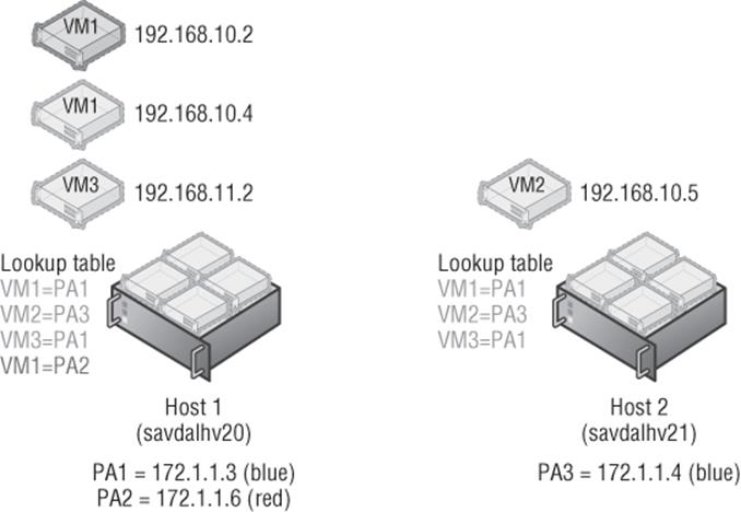
Figure 3.31 Hyper-V configuration for my basic lab environment
To view all the virtual subnets and the virtual network (routing domain) they are part of, a great command is Get-NetVirtualizationCustomerRoute, which shows the details. Note in the following output that we don't see red or blue in these names because they are names that SCVMM is managing. Hyper-V just sees GUIDs for the routing domains (the virtual networks) and the virtual subnet IDs.
PS C:\> Get-NetVirtualizationCustomerRoute
RoutingDomainID : {3B10FAC6-5593-477B-A31E-632E0E8C3B5E}
VirtualSubnetID : 16200119
DestinationPrefix : 192.168.10.0/24
NextHop : 0.0.0.0
Metric : 0
RoutingDomainID : {0CF58B26-4E00-4007-9CD0-C7847D965BC9}
VirtualSubnetID : 6836310
DestinationPrefix : 192.168.11.0/24
NextHop : 0.0.0.0
Metric : 0
RoutingDomainID : {0CF58B26-4E00-4007-9CD0-C7847D965BC9}
VirtualSubnetID : 6864375
DestinationPrefix : 192.168.10.0/24
NextHop : 0.0.0.0
Metric : 0
Notice that the two last virtual subnets have the same outing domain ID; this is because they are within the same virtual network (blue).
It's very common when troubleshooting to just want to test connectivity, and commonly the ping command is used. However, this won't actually work for provider addresses. The secret is to use the new -p switch, which tells ping to use the provider address instead of regular addresses:
C:\>ping -p 172.1.1.4
Pinging 172.1.1.4 with 32 bytes of data:
Reply from 172.1.1.4: bytes=32 time=1ms TTL=128
Reply from 172.1.1.4: bytes=32 time=1ms TTL=128
Reply from 172.1.1.4: bytes=32 time<1ms TTL=128
Reply from 172.1.1.4: bytes=32 time<1ms TTL=128
Ping statistics for 172.1.1.4:
Packets: Sent = 4, Received = 4, Lost = 0 (0% loss),
Approximate round trip times in milli-seconds:
Minimum = 0ms, Maximum = 1ms, Average = 0ms
It's also possible to use the new Test-VMNetworkAdapter cmdlet to actually ping CA addresses for a virtual machine from the Hyper-V host to ensure connectivity to the actual CA space. To use Test-VMNetworkAdapter, you need to know the MAC address of the next “hop” in communication between the source CA and destination CA address, which can be found using the Select-NetVirtualizationNextHop cmdlet as in the following example:
PS C:\> Select-NetVirtualizationNextHop -SourceCustomerAddress 192.168.10.4 ´
-DestinationCustomerAddress 192.168.11.2 -SourceVirtualSubnetID 6864375
SourceCustomerAddress : 192.168.10.4
DestinationCustomerAddress : 192.168.11.2
SourceVirtualSubnetID : 6864375
NextHopAddress : 192.168.10.1
SourceMACAddress : 001dd8b71c02
NextHopMACAddress : 00508c125f46
Note that because these virtual machines are in different virtual subnets, the next hop is actually the gateway. If they were on the same virtual subnet, there would be no next-hop address and the next-hop MAC would be the target virtual machine network adapter, as shown in the following output.
PS C:\> Select-NetVirtualizationNextHop -SourceCustomerAddress 192.168.10.4 ´
-DestinationCustomerAddress 192.168.10.5 -SourceVirtualSubnetID 6864375
SourceCustomerAddress : 192.168.10.4
DestinationCustomerAddress : 192.168.10.5
SourceVirtualSubnetID : 6864375
NextHopAddress : 0.0.0.0
SourceMACAddress : 001dd8b71c02
NextHopMACAddress : 001dd8b71c04
Once the MAC address of the next hop is known, the Test-VMNetworkAdapter cmdlet can be used to populate the required details, such as the source VM name and the MAC address for the next hop. Ensure that the virtual machine name specified is the source virtual machine name, and if the virtual machine had multiple network adapters, you need to pass the specific virtual network adapter to use. The way Test-VMNetworkAdapter works is to actually hook directly into the virtual switch, inject the ICMP packet to the destination, and then capture the return pack and return the result. The benefit of this command is that you can use it where you cannot just perform a ping from within the virtual machines, such as if you are an administrator at a service provider and the tenants using the virtual networks do not give you logon privileges. With the Test-VMNetworkAdapter cmdlet, you can test the communication between virtual machines in a virtual network without having to actually log on to them.
PS C:\> Test-VMNetworkAdapter -Sender -SenderIPAddress 192.168.10.4 '
-ReceiverIPAddress 192.168.11.2 -VMName “Blue-VM-1” '
-NextHopMacAddress “00508c125f46” -SequenceNumber 100
RoundTripTime : 2 milliseconds
Windows 2012 R2 introduces support for dynamic learning of IP addresses used in the CA space. This is useful if you're using DHCP within a CA space or running clusters within the CA space, which will have cluster IP addresses that will need to move between virtual machines. I do want to point out that SCVMM by default will intercept any DHCP requests via its DHCP virtual switch extension and allocate IP addresses from its IP pools. If this was disabled, though, it would then be possible to run DHCP servers within a CA space. I mention this here because if you wish to use this dynamic learning, then the configuration is performed using PowerShell. The following commands create a Layer 2 Only type lookup record, which means it's a dynamic learning record. Notice that I specify the MAC address of the virtual machine's network adapter. Now when the VM uses DHCP and gets an IP address, the routing table will be dynamically updated with this learned IP address.
$ProviderAddressHost="172.1.1.3"
$vsid = 6864375
$DHCPClientMAC = "020203030404"
New-NetVirtualizationLookupRecord -CustomerAddress 0.0.0.0 ´
-VirtualSubnetID $vsid -MACAddress $DHCPClientMAC ´
-ProviderAddress $ProviderAddressHost -Type L2Only ´
-Rule TranslationMethodEncap
I've shown you the manual way of enabling a DHCP client using PowerShell on the Hyper-V host. Remember though, when using SCVMM, you need to not perform configurations directly on the Hyper-V hosts, especially configurations related to network virtualization, because the changes will not be known by SCVMM and therefore will get lost. To enable the guest learning IP address capability, you use the “Allow guest specified IP addresses (only available for virtual machines on Windows Server 2012 R2)” security setting for the virtual port profile used. This is configured by default in the Guest Dynamic IP inbox virtual port profile.
Network Virtualization Gateway
While the isolation provided by virtual networks is a powerful feature and provides islands of communication, there will be times you want communication outside of a virtual network. To enable virtual machines in a virtual network to communicate outside of their network -virtualization-provided network, you must use a Network Virtualization Gateway, or NV Gateway. This is different from the gateway functionality that is provided by the Hyper-V network virtualization filter running in the Hyper-V switch, which routes traffic between virtual subnets in the same virtual network. The functionality I am referring to now is related to communication between different virtual networks and to other networks such as the Internet, a corporate network, or even another location. If you have a virtual network that wants to talk to the outside world, then it needs to use a NV Gateway. In the future, I think physical switches will start to support certain NV Gateway features such as switching and forwarding, but today a separate NV Gateway is required.
In Windows Server 2012 Hyper-V, this was a problem because no NV Gateway was provided and instead it was necessary to use a third-party NV Gateway solution. In Windows Server 2012 R2, you can still use a third-party NV Gateway, but one is also now provided in-box, the Hyper-V Network Virtualization Gateway, commonly known as HNV Gateway.
There are three types of gateway functionality provided by the HNV Gateway, and the one you will use depends on your requirements and configuration:
1. Forwarding Gateway This can be used if the IP scheme used in the virtual network is essentially an extension of your existing IP scheme and would be routable on the network. The gateway simply forwards packets between the physical network fabric and the virtual network. A HNV Gateway in forwarding mode only supports a single virtual network. This means if you need forwarding for 10 virtual networks, you need 10 separate HNV Gateways.
2. NAT Gateway If the IP schemes used in the virtual networks would not be routable on the physical fabric and/or have overlapping IP schemes between virtual networks, then Network Address Translation (NAT) must be used between the virtual network and the physical fabric. An HNV Gateway in NAT can support up to 50 virtual networks.
3. Site-to-Site (S2S) Gateway
An S2S gateway provides a connection from a virtual network to another network using a VPN connection. In most enterprise environments, there is already IP connectivity between locations, so this would not be required. However, consider a hoster scenario where a tenant wants to talk to their on-premises network. The HNV Gateway S2S could be used to connect the tenant's virtual network to their physical network. A single gateway can support 200 VPN tunnels.
A single virtual network can have multiple S2S connections, providing redundancy of connectivity failure. If I wanted to connect an on-premises virtual network and a Windows Azure virtual network, I would also use the S2S Gateway option.
Also remember that SCVMM is key to the control and management plane. If different SCVMM instances are used for different locations, then you will require a gateway to connect the virtual networks together because they will not share policies and will have separate routing tables. S2S uses the RRAS functionality of Windows Server 2012 R2. The other types of gateways do not leverage RRAS.
Deploying a HNV Gateway
The HNV Gateway is a virtual machine (it cannot be a physical host) running on a Windows Server 2012 R2 Hyper-V host, but there is a caveat. The Hyper-V host running the HNV Gateway cannot host any virtual machines that are members of a virtual network. Essentially, you need a dedicated Hyper-V host that will not participate in network virtualization except for the purposes of the HNV Gateway virtual machines that will be deployed.
The virtual machines that act as HNV Gateways will have a number of virtual network adapters connected to different networks:
· Connection to the network that needs to be connected from the virtual networks (for example, connection to the corporate network or the Internet network)
· Connection to the virtual network(s)
· (Optional) Separate management network connection
· (Optional) Cluster networks if highly available
Note that when a HNV Gateway is enabling connectivity for multiple virtual networks such as with NAT or S2S, then each virtual network is implemented using a separate networking TCP compartment, which is a new Windows Server 2012 R2 concept and enables the different network connectivities to be isolated from other network connectivities.
The first step is to specify that the Hyper-V host that will host the HNV Gateway virtual machines should not be used for normal network virtualization.
1. In Virtual Machine Manager, select the Fabric workspace.
2. Under Servers, expand the All Hosts host group, right-click on the Hyper-V host that will host the gateways, and select Properties.
3. Select the Host Access Tab.
4. Check the box labeled “This host is a dedicated network virtualization gateway, as a result it is not available for placement of virtual machines requiring network virtualization” and click OK, as shown in Figure 3.32.
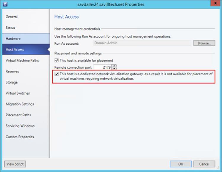
Figure 3.32 Enabling a host for HNV Gateway use only
The next step is to actually deploy the gateway virtual machine. This will vary depending on the network being connected to; for example, high availability may be required, or you may need a separate management network. There is a great document available from
www.microsoft.com/en-us/download/details.aspx?id=39284
It covers every scenario, so I recommend downloading it and reading it. It walks you through setting up HNV Gateway for S2S, NAT, and Forwarding. It also covers creating a specific VM template and a service template to quickly deploy new gateways. This is important if you are hosting tenants and want to provide them with the ability to deploy their own gateways to connect their virtual networks to on-premises or even the Internet, they need a simple way which is provided by using service templates. Microsoft has a service template available for both stand-alone and highly available gateway deployments that simplifies the work. They are available from the Web Platform Installer (PI) feed in SCVMM. I highly recommend using the service templates because they automate all of the various configurations required.
For now, I will walk through a very basic setup with a gateway virtual machine with two network connections: one to the lab network to which I want to enable connectivity from the virtual networks and one that will eventually connect to the logical network that is used for network virtualization but initially must be configured as “Not connected.”
1. Deploy a Windows 2012 R2 virtual machine and make sure it has two network adapters, one not connected to any network and the other connected to the network that is the target network for connectivity from the virtual networks configured with static IP from the IP pool. Ensure that the VM is deployed to a Hyper-V host that has been configured to be used for network virtualization gateways.
2. Within the virtual machine you created, make sure the firewall is disabled for all profiles. This can be done through the Windows Firewall with Advanced Security application or with the following command:
Set-NetFirewallProfile -Profile Domain,Public,Private -Enabled False
3. The Routing and DirectAccess and VPN role services of Remote Access must be installed in the VM along with the Remote Access module for the Windows PowerShell feature. This can be done using Server Manager or using the following PowerShell command:
Install-WindowsFeature RSAT-RemoteAccess-PowerShell, DirectAccess-VPN, Routing
4. Once the virtual machine is deployed, open its properties page, select the Hardware Configuration tab, and navigate to the second network adapter that was not connected. Select the Connected To A VM Network option and click Browse. In the Select A VM Network window, click the Clear Selection button and then click OK. This allows the option to select a standard switch, which should be the switch that exists on the host. It is not connecting via a VM network, though, which is a key detail, as shown in Figure 3.33. Click OK. Once the change has taken effect, start the virtual machine.
5. The next step is to configure the virtual machine as a gateway to SCVMM. Open the Fabric workspace and expand Networking ⇒ Network Service. Right-click Network Service and select the Add Network Service action.
6. The Add Network Service Wizard will launch and ask for a name and description of the new service. I typically use the name of the gateway VM as the name for the service. Click Next.
7. Select Microsoft as the manufacturer and set the Model to Microsoft Windows Server Gateway. Click Next.
8. Select a Run As account that has local administrator privileges on the virtual machine and then click Next.
9. The connection string for the gateway needs to be configured. It is made up of the Hyper-V host hosting the virtual machine and the virtual machine's name; for example, in Figure 3.34 it is
VMHost=savdalhv24.savilltech.net;GatewayVM=HNV-GW-1
Click Next.
10.A certificates screen appears. It is not used for this configuration, so just click Next.
11.The connection to the virtual machine can be tested using the Test button. It's important that Test Open Connection, Test Capability Discovery, and Test System Info all show Passed. Click Next.
12.Next, specify the host group where the HNV gateway can be used. For example, I would specify my Dallas host group. Click Next.
13.Click Finish to go ahead and configure the gateway for virtualization.
14.Once the configuration is complete, right-click the new network service and select Properties. Then select the Connectivity Tab.
15.You need to tell SCVMM which of the adapters in the VM is the backend connection (i.e., connects to the network virtualizations side and is the adapter we directly connected to the switch) and which is the front-end connection (i.e., connects to the target external network such as the Internet or corporate). It's very important that you get this right. In my gateway, I renamed the NICs to make it simpler, and the Microsoft service template actually does this for you automatically as well! You can see in Figure 3.35 that I made my selections.
Click OK and changes will be made to the gateway virtual machine. This may take a few minutes. Monitor the Jobs workspace to confirm when the gateway configuration has completed.
16.The final step is to configure a virtual network to use the new gateway service you created to enable connectivity beyond the virtual network. Open the virtual network via the VMs And Services workspace ⇒ VM Networks. Select the Connectivity tab. It's now possible to select to enable additional types of connectivity using your new gateway for the various types of routing. As shown in Figure 3.36, I am using the gateway for NAT connectivity for this virtual network because its IP scheme is not routable on the network being connected to.
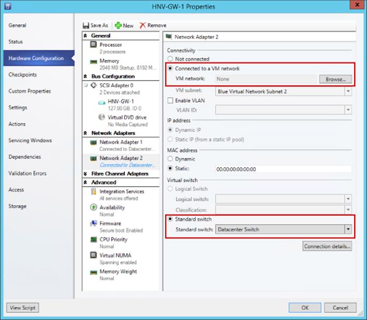
Figure 3.33 Properties for the network adapter used to connect to the virtual networks
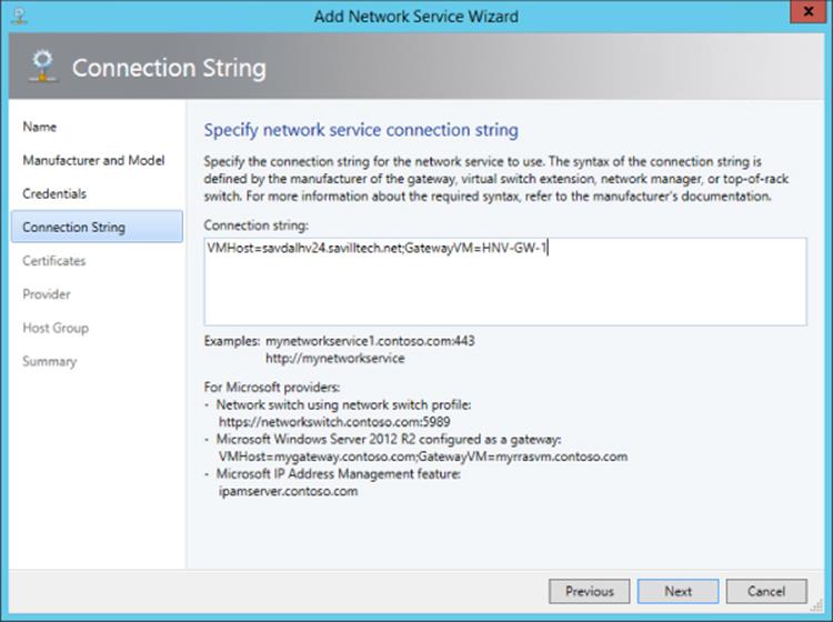
Figure 3.34 Configuring the connection string. Notice that a number of examples are shown on the dialog.
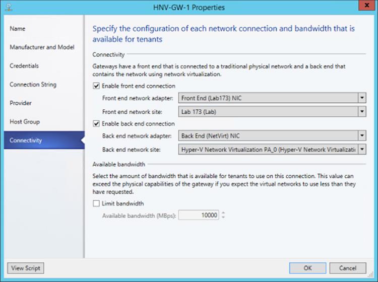
Figure 3.35 Configuring the new gateway network service
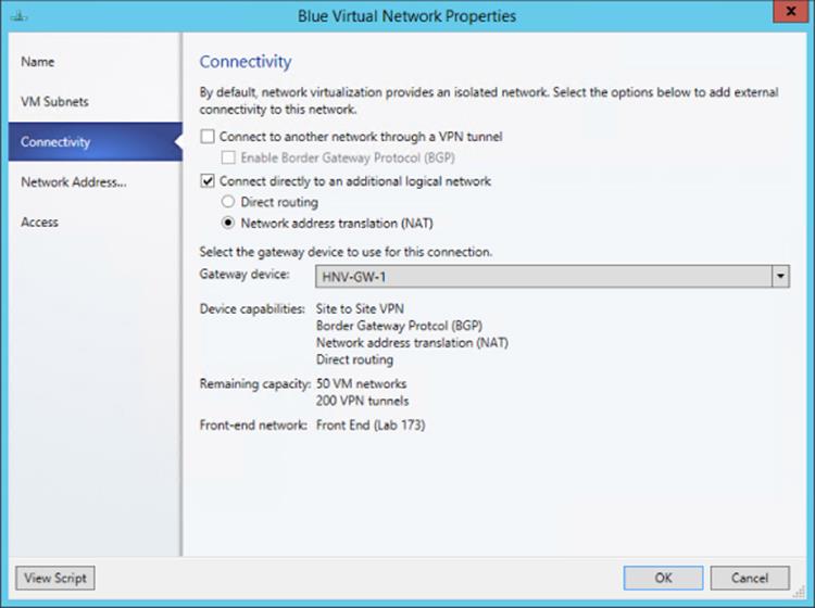
Figure 3.36 Configuring the new gateway network service
Within my virtual network I can now communicate with the external network. Providing I have DNS configured on the virtual machines in the virtual network, I can now access external resources.
That took quite a lot of steps. It would be simpler if you use the service templates provided by Microsoft, but it's good to know how to perform these steps manually, especially if you have to perform any troubleshooting.
Behind the Curtain of the HNV Gateway
Previously I talked about the TCP compartments that are used within the HNV Gateway to enable multiple tenants (virtual networks) to be serviced using a single HNV Gateway instance. During the whole process of creating the HNV Gateway, it was never required to perform any routing configurations on the actual virtual machine, but behind the scenes SCVMM was remotely configuring services and the TCP compartments required for the different types of gateways required. Figure 3.37 shows an example of the TCP compartments in my lab environment with the red and blue virtual networks for NAT gateway functionality. As can be seen, there is a default compartment for the operating system, which is also where NAT functionality is performed, and then there is a separate TCP compartment for each of the virtual networks that contains an interface for the virtual network to which it belongs.
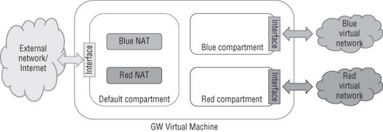
Figure 3.37 Overview of TCP compartments used in the HNV Gateway
If you log on to the HNV Gateway virtual machine, you can use PowerShell commands to inspect the TCP compartments. To see all compartments, use the Get-NetCompartment command as shown here:
PS C:\> Get-NetCompartment
CompartmentId : 1
CompartmentDescription : Default Compartment
CompartmentGuid : {b1062982-2b18-4b4f-b3d5-a78ddb9cdd49}
CompartmentId : 2
CompartmentDescription : Blue Virtual Network0cf58b26-4e00-4007-9cd0-c7847d965bc9
CompartmentGuid : {0cf58b26-4e00-4007-9cd0-c7847d965bc9}
CompartmentId : 3
CompartmentDescription : Red Virtual Network3b10fac6-5593-477b-a31e-632e0e8c3b5e
CompartmentGuid : {3b10fac6-5593-477b-a31e-632e0e8c3b5e}
This shows my three compartments as previously mentioned. It is then possible to look at the actual interfaces configured in each compartment. The following output shows the interfaces for the blue compartment. Note that you should not have to ever look at this. SCVMM is doing all the work for you, but if you were not using SCVMM, you would need to manually create the compartments, perform the configuration, and so on.
PS C:\> Get-NetIPInterface -IncludeAllCompartments -CompartmentId 2
ifIndex InterfaceAlias AddressFamily NlMtu(Bytes) InterfaceMetric Dhcp ConnectionState PolicyStore
------- -------------- ------------- ------------ ---------------- --------------- ---------
31 WNVAdap_6865744 IPv6 1458 5 Disabled Connected Active…
30 Loopback Pseudo-Interface 2 IPv6 4294967295 50 Disabled Connected Active…
31 WNVAdap_6865744 IPv4 1458 5 Disabled Connected Active…
30 Loopback Pseudo-Interface 2 IPv4 4294967295 50 Disabled Connected Active…
Summary
There are some workloads that do not work with network virtualization today. PXE boot, which enables booting an operating system over the network, will not function. DHCP is supported in Windows Server 2012 R2 Hyper-V as previously mentioned, but SCVMM has its own switch extension to intercept DHCP to allocate from IP pools, so normal DHCP in a VM would not work when you're managing your network with SCVMM. The SCVMM load balancer configuration capability as part of a service deployment does not work when using network virtualization; the load balancer would have to be configured “out-of-band.”
To summarize, you can use the following types of isolation methods in your Hyper-V environment:
1. Physical Use separate physical network switches and adapters to provide isolation between networks. Not scalable and costly and complex.
2. External Using virtual switch extensions, specifically the forwarding extension such as Cisco Nexus 1000V or NEC OpenFlow, can provide isolation in the switch using native technologies. This is, however, fairly opaque to SCVMM.
3. VLAN Layer 2 technology provides isolation and broadcast boundary on a shared network, but the number of VLANs is limited and can become complex to manage. Does not allow IP address overlap between VLANs, nor does it allow flexibility for business units/tenants to bring their own IP scheme to the environment.
4. PVLAN Utilizes a pair of VLANs to provide an isolated network in different modes, but most commonly allows many virtual machines to communicate with a common set of resources/Internet while being completely isolated from each other.
5. Network Virtualization Abstraction of the virtual machine network from the physical network fabric provides maximum capability without the limitations and complexity of other technologies. Allows users of network virtualization to bring their own IP scheme and even IP overlap between different virtual networks. Network Virtualization gateways allow virtual networks to communicate with external networks.
Where possible, utilize network virtualization for its flexibility and relative ease of configuration. However, for some types of network, such as management networks, it will still be common to use more traditional isolation methods such as VLAN technologies.
VMQ, RSS, and SR-IOV
So far we have covered a lot of technologies related to network connectivity. However, in the following sections, I want to cover a few technologies that can help with the performance of network communications. Although it can introduce some challenges when trying to maximize its utilization and gain the highest levels of performance and bandwidth, 10 Gbps and beyond is becoming more common in many datacenters.
SR-IOV and Dynamic Virtual Machine Queue (DVMQ) are two popular networking technologies that can help with network performance and also can minimize overhead for the hypervisor. These technologies are shown in Figure 3.38.
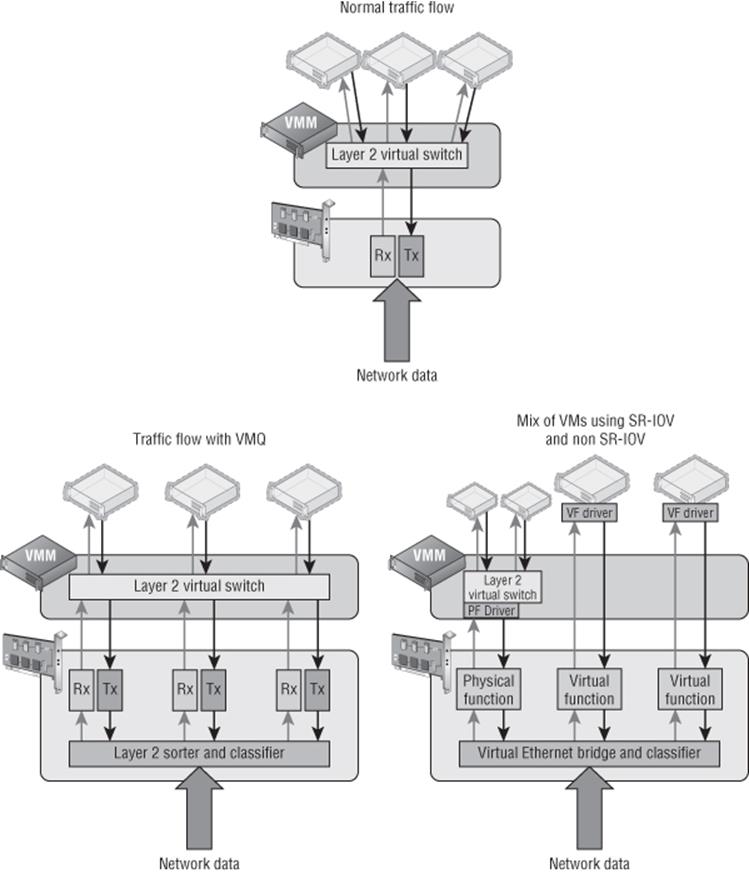
Figure 3.38 Understanding the VMQ and SR-IOV network technologies compared to regular networking
SR-IOV
Single root I/O virtualization (SR-IOV) allows a single PCI Express network device to represent itself as multiple separate devices directly to virtual machines. In the case of SR-IOV and virtual machines, this means a physical NIC can actually present multiple virtual NICs, which in SR-IOV terms are called virtual functions (VFs). Each VF is of the same type as the physical card and is presented directly to specific virtual machines. The communication between the virtual machine and the VF is now completely bypassing the Hyper-V switch because the VM uses Direct Memory Access (DMA) to communicate with the VF. This makes for very fast and very low-latency communication between the VM and the VF because both the VMBus and the Hyper-V switch are no longer involved in the network flow from the physical NIC to the VM. Because the Hyper-V switch is bypassed when SR-IOV is used, SR-IOV is disallowed if any ACL checking, QoS, DHCP Guard, third-party extensions, Network Virtualization, or any other switch features are in use. SR-IOV use is permitted only when no switches' features are active.
SR-IOV does not break Live Migration, a technology not covered yet, but allows virtual machines to move between hosts with no downtime, even when you're moving a virtual machine to a host that does not support SR-IOV. Behind the scenes when SR-IOV is used, the Network Virtualization Service Client (NetVSC) actually creates two paths for the virtual machine network adapter inside the VM. One path is via SR-IOV and one is using the traditional VMBus path, which uses the Hyper-V switch. When the VM is running on a host with SR-IOV, the SR-IOV path is used and the VMBus is used only for control traffic, but if the VM is moved to a host without SR-IOV, then the SR-IOV path is closed by NetVSC and the VMBus path is used for data and control traffic; this is all transparent to the virtual machine. It means you don't lose any mobility even when using SR-IOV. To use SR-IOV, both the network adapter and the motherboard must support it. To use SR-IOV with a virtual switch, the option to use SR-IOV must be selected at the time of the virtual switch creation as shown in Figure 3.39. If you're using the New-VMSwitch cmdlet to create the virtual switch, use the -EnableIov $True parameter to enable SR-IOV. On the Hardware Acceleration property tab of the virtual network adapter for a virtual machine that needs to use SR-IOV, ensure that the Enable SR-IOV check box is selected.
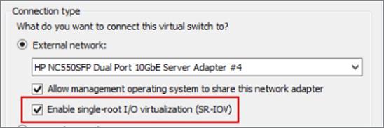
Figure 3.39 Enabling SR-IOV on a virtual switch at creation time
To check your server for SR-IOV support, there are a number of commands you can run. To start with, run PowerShell command Get-VMSwitch | Format-List *iov* as shown here. Note that this example shows that the network adapter supports SR-IOV, but it is not supported because of limitations on the server motherboard and BIOS.
PS C:\> Get-VMSwitch | Format-List *iov*
IovEnabled : True
IovVirtualFunctionCount : 0
IovVirtualFunctionsInUse : 0
IovQueuePairCount : 0
IovQueuePairsInUse : 0
IovSupport : False
IovSupportReasons : {To use SR-IOV on this system, the system BIOS
must be updated to allow Windows to control
PCI Express. Contact your system manufacturer for an update., This system has a security
vulnerability in the system I/O remapping hardware. As a precaution, the ability to use
SR-IOV has been disabled. You should contact your system manufacturer for an updated BIOS
which enables Root Port Alternate Error Delivery mechanism. If all Virtual Machines
intended to use SR-IOV run trusted workloads, SR-IOV may be enabled by adding a registry
key of type DWORD with value 1 named IOVEnableOverride under
HKEY_LOCAL_MACHINE\SOFTWARE\Microsoft\Windows NT\CurrentVersion\Virtualization and changing
state of the trusted virtual machines. If the system exhibits reduced performance or
instability after SR-IOV devices are assigned to Virtual Machines, consider disabling the
use of SR-IOV.}
The following output is from another system that has one adapter that does not support SR-IOV and additional adapters that do support it:
PS C:\> Get-VMSwitch | Format-List *iov*
IovEnabled : False
IovVirtualFunctionCount : 0
IovVirtualFunctionsInUse : 0
IovQueuePairCount : 0
IovQueuePairsInUse : 0
IovSupport : False
IovSupportReasons : {This network adapter does not support SR-IOV.}
IovEnabled : True
IovVirtualFunctionCount : 62
IovVirtualFunctionsInUse : 10
IovQueuePairCount : 63
IovQueuePairsInUse : 10
IovSupport : True
IovSupportReasons : {OK}
IovEnabled : True
IovVirtualFunctionCount : 6
IovVirtualFunctionsInUse : 2
IovQueuePairCount : 7
IovQueuePairsInUse : 2
IovSupport : True
IovSupportReasons : {OK}
It's also possible to run the PowerShell command Get-NetAdapterSriov to get SR-IOV support adapter information on a system; it also shows the number of virtual functions (VFs) supported by the card. If a virtual machine is using SR-IOV successfully, then when you look at the Networking tab of the virtual machine in Hyper-V Manager, that status will show “OK (SR-IOV active).”
PS C:\> Get-NetAdapterSriov
Name : Ethernet 3
InterfaceDescription : Intel(R) Gigabit ET2 Quad Port Server Adapter #2
Enabled : True
SriovSupport : Supported
SwitchName : DefaultSwitchName
NumVFs : 6
Name : Ethernet 6
InterfaceDescription : Intel(R) Gigabit ET2 Quad Port Server Adapter #4
Enabled : True
SriovSupport : Supported
SwitchName : DefaultSwitchName
NumVFs : 6
The reality right now is that not many systems are SR-IOV capable and SR-IOV would be used in targeted scenarios because in most situations, the standard Hyper-V network capabilities via the virtual switch will suffice for even the most demanding workloads. SR-IOV is targeted at those very few highest networking throughput needs. The other common place where SR-IOV implementations can be found is in “cloud in a box” type solutions where a single vendor supplies the servers, the network, and the storage. The one I have seen commonly is the Cisco UCS solution that leverages SR-IOV heavily because many network capabilities are actually implemented using Cisco's own technology, VM-FEX. An amazing multipart blog is available from Microsoft on SR-IOV; it will tell you everything you could ever want to know.
http://blogs.technet.com/b/jhoward/archive/2012/03/12/everything-you-wanted-to-know-about-sr-iov-in-hyper-v-part-1.aspx
DVMQ
A technology that's similar to SR–IOV is Dynamic Virtual Machine Queue (DVMQ). VMQ, which was introduced in Windows Server 2008 R2, allows separate queues to exist on the network adapter, with each queue being mapped to a specific virtual machine. This removes some of the switching work on the Hyper-V switch because if the data is in this queue, the switch knows it is meant for a specific virtual machine. The bigger benefit is because there are now separate queues from the network adapter, that queue can be processed by a different processor core. Typically, all the traffic from a network adapter is processed by a single processor core to ensure that packets are not processed out of sequence. For a 1Gbps network adapter, this may be fine, but a single core could not keep up with a loaded 10 Gbps network connection caused by multiple virtual machines. With VMQ enabled, specific virtual machines allocate their own VMQ on the network adapter, which allows different processor cores in the Hyper-V host to process the traffic, leading to greater throughput. (However, each virtual machine would still be limited to a specific core, leading to a bandwidth cap of around 3 to 4 Gbps, but this is better than the combined traffic of all VMs being limited to 3 to 4 Gbps.)
The difference between VMQ and SR-IOV is that the traffic still passes through the Hyper-V switch with VMQ because all VMQ presents are different queues of traffic and not entire virtual devices. In Windows Server 2008 R2, the assignment of a VMQ to a virtual machine was static; typically first come, first served because each NIC supports a certain number of VMQs and each VMQ was assigned (affinitized) in a round-robin-type manner to the logical processors available to the host, and this would never change. The assignment of VMQs is still on a first come, first served basis in Windows Server 2012, but the allocation of processor cores is now dynamic and fluid. This allows the queues to be moved between logical processors based on load. By default, all queues start on the same logical processor, the home processor, but as the load builds on a queue, Hyper-V can move the individual queues to a different logical processor to more efficiently handle the load. As the load drops, the queues can be coalesced back to a smaller number of cores and potentially all back to the home processor.
Many modern network cards support VMQ, and this is easy to check using the PowerShell Get-NetAdapterVmq command. In the following example, I can see that VMQ is enabled on two of my network adapters because they are currently connected to a Hyper-V virtual switch. If network adapters are not connected to a virtual switch, their VMQ capabilities will not be shown.
PS C:\> Get-NetAdapterVmq |ft Name, InterfaceDescription,Enabled,NumberOfReceiveQueues -AutoSize
Name InterfaceDescription Enabled NumberOfReceiveQueues
---- -------------------- ------- ---------------------
J_ETH4 Broadcom BCM57800 NetXtreme ) #132 False 0
10Gbps NIC2 Broadcom BCM57800 NetXtreme IIt) #130 True 14
MGMT NIC Broadcom BCM57800 NetXtreme II) #131 False 0
10Gbps NIC1 Broadcom BCM57800 NetXtreme Int) #129 True 14
By default, if a virtual network adapter is configured to be VMQ enabled, there is no manual action required, and based on the availability of VMQs, a VMQ may be allocated and used by a virtual machine. Figure 3.40 shows the Hardware Acceleration setting for a virtual network adapter, and also notice in the main Hyper-V Manager window to the left, at the bottom of the screen, it shows that VMQ is actually being used because the Status column is set to OK (VMQ Active). Remember that just because a network adapter is configured to use VMQ does not mean it will be allocated a VMQ. It depends on if one is available on the network adapter when the VM is started.
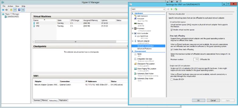
Figure 3.40 Ensuring that VMQ is enabled for a virtual machine
To check which virtual machines are actually using VMQs and also which processor core is currently being used by the queue, you can use the Get-NetAdapterVmqQueue PowerShell command. In the following example, you can see that VM1 and VM2 each have a queue but are running on the home processor, as is the default queue, which is used for traffic that is not handled by a separate VMQ. There is no way to force a virtual machine to always be allocated a VMQ. The only way would be to make sure those virtual machines that you want to have a VMQ are started first when the host is started.
PS C:\> Get-NetAdapterVmqQueue
Name QueueID MacAddress VlanID Processor VmFriendlyName
---- ------- ---------- ------ --------- --------------
10Gbps NIC2 0 0:0 SAVDALHV23
10Gbps NIC1 0 0:0 SAVDALHV23
10Gbps NIC1 1 00-15-5D-AD-17-00 0:0 VM1
10Gbps NIC1 2 00-15-5D-AD-17-01 0:0 VM2
You may wonder how VMQ works if you are using NIC Teaming, and the answer is that it actually varies depending on the mode of NIC Teaming. Consider that it's possible to mix network adapters with different capabilities in a NIC team. For example, one NIC supports 8 VMQs and another supports 16 VMQs in a two-NIC team. There are two different numbers that are important:
· Min Queues: The lower number of queues supported by an adapter in the team. In my example, 8 would be the Min Queue value.
· Sum of Queues: The total number of all queues across all the adapters in the team. In my example, this would be 24.
The deciding factor for how many VMQs are available to a NIC team depends on the teaming mode and the load balancing algorithm used for the team. If the teaming mode is set to switch dependent, then the Min Queues value is always used. If the teaming mode is switch independent and the algorithm is set to Hyper-V Port or Dynamic, then the Sum of Queues value is used; otherwise, Min Queues is used. Table 3.2 shows this in simple form.
Table 3.2 VMQ NIC Teaming options
Address Hash |
Hyper-V Port |
Dynamic |
|
Switch Dependent |
Min Queues |
Min Queues |
Min Queues |
Switch Independent |
Min Queues |
Sum of Queues |
Sum of Queues |
RSS and vRSS
I previously talked about a 3 to 4 Gbps bandwidth limit, which was caused by the amount of traffic that could be processed by a single processor core, and even with VMQ, a virtual machine network adapter is still limited to traffic being processed by a single core. Physical servers have a solution to the single-core bottleneck for inbound traffic, Receive Side Scaling, or RSS. RSS must be supported by the physical network adapter, and the technology enables incoming traffic on a single network adapter to be processed by more than a single processor core. This is enabled using the following flow:
1. Incoming packets are run through a 4-tuple hash algorithm that uses the source and destination IP and ports to create a hash value.
2. The hash is passed through an indirection table that places all traffic with the same hash on a specific RSS queue on the network adapter. Note that there are only a small number of RSS queues. Four is a common number, so a single RSS queue will contain packets from many different hash values, which is the purpose of the indirection Table.
3. Each RSS queue on the network adapter is processed by a different processor core on the host operating system, distributing the incoming load over multiple cores.
Creating the hash value to control which RSS queue and therefore which processor core is important because problems occur if packets are processed out of order, which could happen if packets were just randomly sent to any core. Creating the hash value based on the source and destination IP addresses and port ensures that specific streams of communication are processed on the same processor core and therefore are processed in order. A common question is, What about hyper-threaded processor cores? RSS does not use hyperthreading and actually skips the “extra” logical processor for each core. This can be seen if the processor array and indirection table is examined for an RSS-capable network adapter, as shown in the following output. Notice that only even number cores are shown; 1, 3, and so on are skipped because this system has hyperthreading enabled and so the hyperthreaded cores are skipped.
PS C:\> Get-NetAdapterRss
Name : MGMT NIC
InterfaceDescription : Broadcom BCM57800 NetXtreme II 1 GigE (NDIS VBD Client) #131
Enabled : True
NumberOfReceiveQueues : 4
Profile : NUMAStatic
BaseProcessor: [Group:Number] : 0:0
MaxProcessor: [Group:Number] : 0:30
MaxProcessors : 16
RssProcessorArray: [Group:Number/NUMA Distance] :
0:0/0 0:2/0 0:4/0 0:6/0 0:8/0 0:10/0 0:12/0 0:14/0
0:16/0 0:18/0 0:20/0 0:22/0 0:24/0 0:26/0 0:28/0 0:30/0
IndirectionTable: [Group:Number] :
0:4 0:20 0:6 0:22 0:4 0:20 0:6 0:22
0:4 0:20 0:6 0:22 0:4 0:20 0:6 0:22
0:4 0:20 0:6 0:22 0:4 0:20 0:6 0:22
0:4 0:20 0:6 0:22 0:4 0:20 0:6 0:22
0:4 0:20 0:6 0:22 0:4 0:20 0:6 0:22
0:4 0:20 0:6 0:22 0:4 0:20 0:6 0:22
0:4 0:20 0:6 0:22 0:4 0:20 0:6 0:22
0:4 0:20 0:6 0:22 0:4 0:20 0:6 0:22
0:4 0:20 0:6 0:22 0:4 0:20 0:6 0:22
0:4 0:20 0:6 0:22 0:4 0:20 0:6 0:22
0:4 0:20 0:6 0:22 0:4 0:20 0:6 0:22
0:4 0:20 0:6 0:22 0:4 0:20 0:6 0:22
0:4 0:20 0:6 0:22 0:4 0:20 0:6 0:22
0:4 0:20 0:6 0:22 0:4 0:20 0:6 0:22
0:4 0:20 0:6 0:22 0:4 0:20 0:6 0:22
0:4 0:20 0:6 0:22 0:4 0:20 0:6 0:22
It's possible to configure the actual processor cores to be used for an RSS adapter by modifying the BaseProcessorNumber, MaxProcessorNumber, and MaxProcessors values using the Set-NetAdapterRss PowerShell cmdlet. This gives the administrator more granular control of the processor resources used to process network traffic. It's also possible to enable and disable RSS for specific network adapters using Enable-NetAdapterRss and Disable-NetAdapterRss.
RSS is a great technology, but it is disabled as soon as a network adapter is connected to a virtual switch. VMQ and RSS are mutually exclusive, which means I do not get the benefit of RSS for virtual network adapters connected to virtual machines, which is why if I have a virtual switch connected to a 10 Gbps NIC, the throughput to a virtual machine is only around 3 to 4 Gbps, the maximum amount a single processor core can process, and this is what was possible with Windows Server 2012. This changes with Windows Server 2012 R2 and the introduction of virtual RSS, or vRSS.
vRSS enables the RSS mechanism of splitting incoming packets between multiple virtual processors within the virtual machine. This means that a virtual machine could now leverage the full bandwidth available; for example, a virtual machine could now receive 10 Gbps over its virtual NIC because the processing is no longer bottlenecked to a single virtual processor core.
For vRSS, the network adapter must support VMQ. The actual RSS work is performed on the Hyper-V host, so using vRSS does introduce some additional CPU load on the host, which is why by default vRSS is disabled in the virtual machine. It must be enabled within the virtual machine the same way regular RSS would be enabled on a physical host:
· Use the Enable-NetAdapterRss PowerShell cmdlet.
· Within the properties of the virtual network adapter inside the virtual machine, select the Advanced tab and set the Receive Side Scaling property to Enabled.
With vRSS enabled, once the processor core processing the network traffic is utilized around 80 percent, the processing will start to be distributed among multiple vCPUs.
A great way to show and maximize the throughput of a network adapter is using Microsoft's ntttcp.exe test tool, which allows for multiple streams to be created as a sender and receiver, therefore maximizing the use of a network connection. The tool can be downloaded from the following location:
http://gallery.technet.microsoft.com/NTttcp-Version-528-Now-f8b12769
Once it's downloaded, copy ntttcp.exe into a virtual machine (with at least four vCPUs and with its firewall disabled) that is connected to a virtual switch that uses a 10 Gbps network adapter (this will receive the traffic) and also to a physical host with a 10 Gbps network adapter (that will send the traffic). Within the virtual machine, run the tool as follows:
Ntttcp.exe -r -m 16,*,<IP address of the VM> −a 16 -t 10
This command puts the virtual machine in a listening mode, waiting for the traffic to arrive. On the physical host, send the traffic using the following command:
Ntttcp.exe -s -m 16,*,<IP address of the VM> −a 16 -t 10
On the virtual machine, it will show that traffic is being received. Open Task Manager and view the CPU in the Performance tab. Ensure that the CPU graph is set to Logical Processors (right-click on the process graph and select Change Graph To ⇒ Logical Processors). Initially, without vRSS, the bandwidth will likely be around 4 to 5 Gbps (depending on the speed of your processor cores, but most important, only a single vCPU will be utilized). Then turn on vRSS within the VM and run the test again. This time the bandwidth will be closer to 10 Gbps and many of the vCPUs will be utilized. This really shows the benefit of vRSS, and in Figure 3.41 and Figure 3.42, you can see my performance view without and with vRSS. Notice both the processor utilization and the network speed.
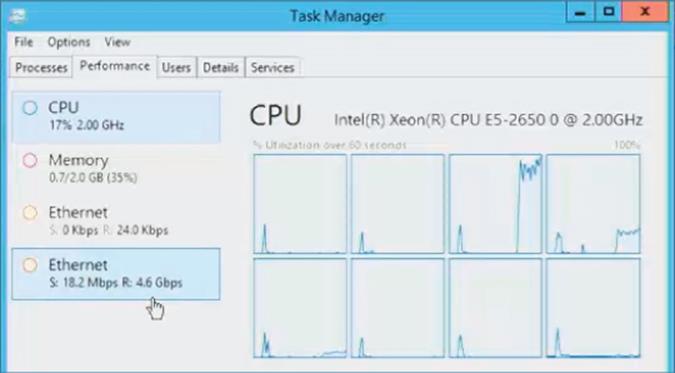
Figure 3.41 Network performance without vRSS enabled
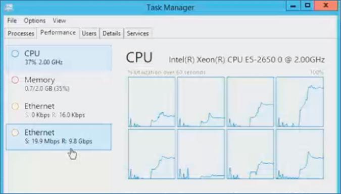
Figure 3.42 Network performance with vRSS enabled
I do want to point out that there is no vRSS support in the host partition. This may not seem important because a host can normally just use RSS. It does become an issue, though, if you create multiple virtual network adapters within the host OS that is connected to a Hyper-V virtual switch. This is possible in Windows 2012 and above and is something I will be talking about later in this chapter. Realize that virtual network adapters in the host partition will be limited in bandwidth to what is possible through a single processor core for each virtual network adapter.
NIC Teaming
As more resources are consolidated onto a smaller number of physical systems, it's critical that those consolidated systems are as reliable as possible. Previously in this chapter, we created virtual switches, some of which were external to connect to a physical network adapter. Many different virtual machines connect to a virtual switch for their network access, which means a network adapter failure in the host would break connectivity for a large number of virtual machines and the workloads running within them. It is therefore important to provide resiliency from network adapter failure and also potentially enable aggregation of bandwidth from multiple network adapters. For example, a solution would be to group four 1 Gbps network adapters together for total bandwidth of 4 Gbps.
The ability to group network adapters together, made possible by a feature known as NIC Teaming, has been a feature of many network drivers for a long time. However, because it was a feature of the network driver, the implementation differed by vendor. It was not possible to mix network adapters from different vendors, and strictly speaking, the technology was not “supported” by Microsoft because it was not Microsoft technology. Windows Server 2012 changed this by implementing NIC Teaming as part of the operating system itself. It allows up to 32 network adapters to be placed in a single NIC team, and the network adapters could be from many different vendors. It's important that all the NICs are the same speed because the Windows NIC Teaming algorithms do not consider NIC speed as part of their traffic balancing algorithms, so if you mixed 1 Gbps network adapters with 10 Gbps network adapters, the 1 Gbps network adapters would receive the same amount of traffic as the 10 Gbps network adapters, which would be far from optimal.
NIC Teaming is simple to configure using Server Manager or using PowerShell. For example, the following command would create a new NIC team using Switch Independent mode, the dynamic load balancing algorithm, and two network adapters:
New-NetLbfoTeam -Name "HostSwitchTeam" -TeamMembers NICTeam3,NICTeam4 ´
-TeamingMode SwitchIndependent -LoadBalancingAlgorithm Dynamic ´
-Confirm:$false
Additionally, as you saw earlier in the chapter, SCVMM can automatically create teams on hosts when deploying logical switches. There are two primary configurations for a NIC team (in addition to specifying which network adapters should be in the team), the teaming mode and the load balancing algorithm. There are three teaming modes:
· Static Teaming: Configuration is required on the switches and computer to identify links that make up the team.
· Switch Independent: Using different switches for each NIC in the team is not required but is possible, and no configuration is performed on the switch. This is the default option.
· LACP (dynamic teaming): The Link Aggregation Control Protocol (LACP) is used to dynamically identify links between the computer and specific switches.
For load balancing, there were two modes in Windows Server 2012 and three in Windows Server 2012 R2:
· Hyper-V Port: Each virtual machine NIC (vmNIC) has its own MAC address, which is used as the basis to distribute traffic between the various NICs in the team. If you have a large number of virtual machines with similar loads, then Hyper-V Port works well, but it can be nonoptimal with a small number of virtual machines or uneven loads. Because a specific vmNIC will always be serviced by the same NIC, it is limited to the bandwidth of a single NIC.
· Address Hash: Creates a hash value based on information such as the source and destination IP and port (although the exact mode can be changed to just use IP or just use MAC). The hash is then used to distribute traffic between the NICs, ensuring that packets with the same hash are sent to the same NIC to protect against out-of-sequence packet processing. This is not typically used with Hyper-V virtual machines.
· Dynamic: New in Windows Server 2012 R2 and really the best parts of Hyper-V Port and Address Hash combined. Outbound traffic is based on the address hash, while inbound traffic uses the Hyper-V Port methods. Additionally, the Dynamic mode uses something called flowlets as the unit of distribution between NICs for outbound traffic. Without flowlets, the entire stream of communication would always be sent via the same network adapter, which may lead to a very unbalanced utilization of network adapters. Consider a normal conversation: There are natural breaks between words spoken, and this is exactly the same for IP communications. When a break of sufficient length is detected, this is considered a flowlet and a new flowlet starts, which could be balanced to a different network adapter. You will pretty much always use the Dynamic mode in Windows Server 2012 R2.
Although it is possible to use the NIC Teaming feature within a virtual machine, only two vmNICs are supported (this is not a hard limit but a supportability limit), and a configuration change is required on the virtual network adapter properties of the virtual machine. This can be done in two ways:
· Within the properties page of the virtual machine, select Advanced Features for the network adapter and check the “Enable this network adapter to be part of a team in the guest operating system” option.
· Use PowerShell and run the following command:
Set-VMNetworkAdapter -VMName <VM Name> −AllowTeaming On
Typically, you will not need to use teaming within the virtual machine. The high availability would be enabled by using NIC teaming at the Hyper-V host level and then the created team would be bonded to the virtual switch. If, for example, you were leveraging SR-IOV, which bypasses the Hyper-V switch, you may wish to create a NIC team within the OS between two SR-IOV network adapters or one SR-IOV and one regular vmNIC.
The addition of NIC Teaming in Windows Server 2012 does not mean NIC Teaming capabilities will no longer be provided by network card vendors. Some vendors differentiate their cards based on teaming capabilities, but customers will have the choice to use teaming capabilities from the network adapter driver or use the Microsoft NIC Teaming functionality, which is fully supported by Microsoft. The decision should be made based on required functionality and supportability needs.
Host Virtual Adapters and Types of Networks Needed in a Hyper-V Host
A Hyper-V host needs many different types of network connectivity, especially if it's part of a cluster. It's critical that each of these types of traffic get the required amount of bandwidth to ensure smooth operation. Additionally, resiliency is likely required for many types of connections to protect against a single network adapter failure. The following key types of network connectivity are required for a Hyper-V host:
· Management: Communication to the host for management such as remote desktop (RDP), WS-MAN for remote PowerShell and Server Manager, and basic file copy operations. Sometimes backup operations will be performed over the management network, or a separate backup network may be required.
· VM: Traffic related to virtual machines connected to a virtual switch.
· Live Migration: The data related to moving a virtual machine between hosts, such as the memory and even storage of a virtual machine.
· Cluster/CSV: Cluster communications and Cluster Shared Volume data.
· SMB 3: Windows 2012 makes SMB an option for accessing storage containing virtual machines, which would require its own dedicated connection.
· iSCSI: If iSCSI is used, a separate network connection would be used.
Traditionally, to ensure the required guaranteed bandwidth for each type of network communication, a separate network adapter was used for each type of traffic. Look at the preceding list again. That is a lot of network adapters, and that list is without resiliency, which may mean doubling that number, which is typically not practical. This is also outlined in the Microsoft networking guidelines at the following location:
http://technet.microsoft.com/en-us/library/ff428137(v=WS.10).aspx
Your connectivity may look like Figure 3.43. Not only does this require a lot of network adapters, but there is a huge amount of wasted bandwidth. For example, typically the Live Migration network would not be used unless a migration is occurring, and normally the Cluster network has only heartbeat and some minimal metadata redirection for CSV, but the high bandwidth is needed for when a Live Migration does occur or when a CSV goes into redirection mode. It would be better if the network bandwidth could be used by other types of communication when the bandwidth was available.
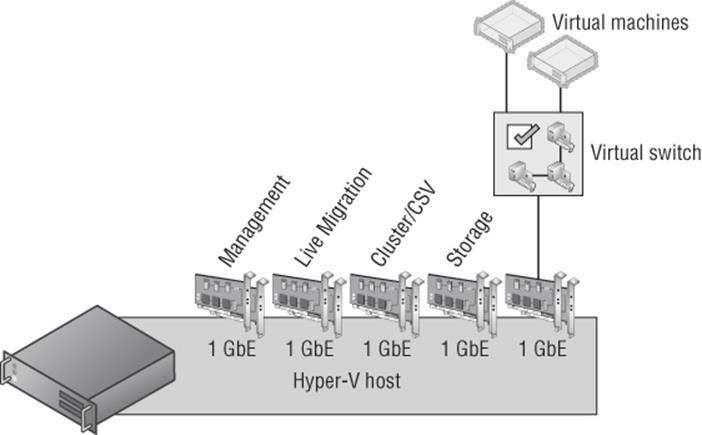
Figure 3.43 A nonconverged Hyper-V host configuration with separate 1 Gbps NIC teams for each type of traffic
Having this many 1 Gbps network adapters may be possible, but as datacenters move to 10 Gbps, another solution is needed in keeping with the converged direction in which many datacenters are focused. Some unified solutions offer the ability to carve up a single connection from the server to the backplane into virtual devices such as network adapters, which is one solution to this problem. It's also possible, however, to solve this using the Hyper-V virtual switch, which traditionally was available only for virtual machines.
One of the properties of a virtual switch is the option to allow the management operating system to share the network adapter, which creates a virtual network adapter (vNIC) on the Hyper-V host itself that was connected to the virtual switch. This would allow the management traffic and the VM traffic to share the virtual switch. It's actually possible, though, to create additional vNICs on the management operating system connected to the virtual switch for other purposes using PowerShell. Quality of Service (QoS) can then be used to ensure that sufficient bandwidth is guaranteed for each of the different vNICs created so that one type of traffic would use up all the bandwidth and stop other types of communication. To add additional vNICs on the Hyper-V host connected to a virtual switch, use the following command (changing the switch name from External Switch to a valid virtual switch name in your environment):
Add-VMNetworkAdapter -ManagementOS -SwitchName “<External Switch>”
The ability to create vNICs in the management operating system connected to a virtual switch that can in turn be connected to a native NIC team that is made up of multiple network adapters makes it possible to create a converged networking approach for the Hyper-V host. Because separate vNICs are used for each type of traffic, QoS can be used to ensure that bandwidth is available when needed, as shown in Figure 3.44. In this example, four 1 Gbps NICs are used together and then used by the virtual switch, which now services virtual machines and the different vNICs in the management partition for various types of communication. However, it would also be common to now use two 10 Gbps NICs instead. I walk through the process in a video at www.youtube.com/watch?v=8mOuoIWzmdE, but here are some of the commands to create two vNICs in the host in a new NIC team and virtual switch. I assign a minimum bandwidth weight QoS policy. If required, each vNIC can be configured with a separate VLAN ID.
New-NetLbfoTeam -Name "HostSwitchTeam" -TeamMembers NICTeam3,NICTeam4 ´
-TeamingMode Static -Confirm:$false
New-VMSwitch "MgmtSwitch" -MinimumBandwidthMode weight ´
-NetAdapterName "HostSwitchTeam" –AllowManagement $false
Add-VMNetworkAdapter -ManagementOS -Name "LiveMigration" -SwitchName "MgmtSwitch"
Set-VMNetworkAdapter -ManagementOS -Name "LiveMigration" ´
-MinimumBandwidthWeight 50
Add-VMNetworkAdapter -ManagementOS -Name "Cluster" -SwitchName "MgmtSwitch"
Set-VMNetworkAdapter -ManagementOS -Name "Cluster" -MinimumBandwidthWeight 50
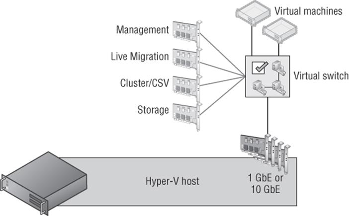
Figure 3.44 A converged Hyper-V host configuration with a shared NIC team used
I go into detail in an article at
http://windowsitpro.com/windows-server-2012/quality-of-service-windows-server-2012
It is definitely worth reading if you want to understand the details of QoS and why minimum bandwidth is a better solution than the traditional maximum bandwidth type caps that always limited the available bandwidth to the cap value, even if there was more bandwidth available. Using minimum bandwidth allows maximum utilization of all bandwidth until there is bandwidth contention between different workloads, at which time each workload is limited to its relative allocation. For example, suppose I have the following three workloads:
· Live Migration: MinumumBandwidthWeight 20
· Virtual Machines: MinumumBandwidthWeight 50
· Cluster: MinumumBandwidthWeight 30
Under normal circumstances, the virtual machines could use all available bandwidth—for example, 10 Gbps if the total bandwidth available to the switch was 10 Gbps. However, if a live migration triggered and the virtual machines were using all the bandwidth, then the virtual machines would be throttled back to 80 percent and the Live Migration traffic would be guaranteed 20 percent, which would be 2 Gbps. Notice that my weights add up to 100, which is not required but is highly recommended for manageability.
Although using this new converged methodology is highly recommended, there is one caveat, and that is the new SMB 3.0 usage. SMB 3.0 has a feature named SMB Direct, which uses remote direct memory access (RDMA) for the highest possible network speeds and almost no overhead on the host. Additionally, SMB 3 has a feature called SMB Multichannel, which allows multiple network connections between the source and target of the SMB communication to be aggregated together, providing both protection from a single network connection failure and increased bandwidth, very similar to the benefits of NIC Teaming. (SMB Direct still works with NIC Teaming because when a NIC team is detected, SMB automatically creates four separate connections by default.) The problem is that RDMA does not work with NIC Teaming. This means if you wish to take advantage of SMB Direct (RDMA), which would be the case if you were using SMB to communicate to the storage of your virtual machines and/or if you are using SMB Direct for Live Migration (which is possible in Windows Server 2012 R2), you would not want to lose the RDMA capability if it's present in your network adapters. If you wish to leverage RDMA, your converged infrastructure will look slightly different, as shown in Figure 3.45, which features an additional two NICs that are not teamed but would instead be aggregated using SMB Multichannel. Notice that Live Migration, SMB, and Cluster (CSV uses SMB for its communications) all move to the RDMA adapters because all of those workloads benefit fromRMDA. While this does mean four network adapters are required to most efficiently support the different types of traffic, all those types of traffic are fault tolerant and have access to increased bandwidth.
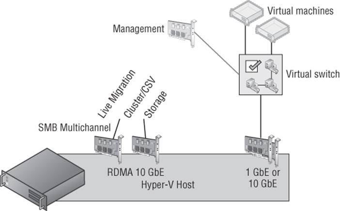
Figure 3.45 A converged Hyper-V host configuration with separate NICs for SMB (RDMA) traffic
Remember the bandwidth limitation when using vNICs in the host as I explained in the section “RSS and vRSS.” vRSS cannot be used in the host partition for the vNICs, which means each vNIC will be limited to 3 to 4 Gbps. This likely will be enough bandwidth for each vNIC for most scenarios, but it's important to remember or you may be confused as to why your live migrations over a vNIC run at 3 Gbps instead of 10 Gbps.
Types of Guest Network Adapters
There are two types of network adapters available to a generation 1 virtual machine: legacy (emulated Intel 21140-Based PCI Fast Ethernet) and synthetic. As was discussed in Chapter 2, “Virtual Machine Resource Fundamentals,” emulated hardware is never desirable because of the decreased performance and higher overhead, which means the legacy network adapter is only really used for two purposes in a generation 1 virtual machine:
· Running an operating system that does not have Hyper-V integration services available and therefore cannot use the synthetic network adapter (this would mean the operating system is also unsupported on Hyper-V).
· Needing to boot the virtual machine over the network, known as PXE Boot. If this is the reason, then initially use a legacy network adapter, but once the operating system is installed, switch to the synthetic network adapter for the improved performance.
Additionally, QoS and hardware acceleration features are not available for legacy network adapters, making the standard network adapter your default choice. Each virtual machine can have up to eight network adapters (synthetic) and four legacy network adapters.
There are many options available for a network adapter that are configured through the virtual machine properties by selecting the network adapter (legacy network adapter or network adapter), and if there are multiple network adapters for a virtual machine, each adapter has its own set of configurations. These configurations are broken down into three areas: core configurations, hardware acceleration (not available for legacy network adapters), and advanced features, as shown in Figure 3.46. Figure 3.46 also shows Device Manager running in the virtual machine whose properties are being displayed, which shows the two network adapters. The Intel 21140-Based PCI Faster Ethernet Adapter (Emulate) is the legacy network adapter and the Microsoft Virtual Machine Bus Network Adapter is the network adapter.
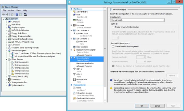
Figure 3.46 Primary properties for a network adapter
The core properties for a network adapter are as follows:
· Virtual Switch: The virtual switch the adapter should be connected to.
· Enable Virtual LAN Identification: If the switch port that the virtual switch is connected to is set to tagged and expects packets to be tagged with a VLAN ID, this option allows you to configure which VLAN ID packets from this network adapter will be tagged.
· Enable Bandwidth Management (not available for legacy network adapter): Enables limits to be specified in Mbps for the bandwidth available for the network adapter. The lowest value allowed for Minimum is 10 Mbps, while 0.1 is the lowest value that can be set for Maximum.
The Hardware Acceleration tab (not available to legacy network adapters) enables VMQ, IPsec, and SR-IOV by checking the appropriate box. Remember that even if these properties are set in a virtual machine, it does not guarantee their use. For example, if the physical network adapter does not support VMQ or has run out of VMQs, then VMQ will not be used for the vmNIC. Likewise, if SR-IOV is selected by the virtual switch, if the hardware does not support SR-IOV, or if the physical adapter has no more available virtual functions, then SR-IOV will not be used. Selecting the options simply enables the capabilities to be used if they are available without guaranteeing their actual use.
The Advanced Features tab enables a number of interesting options whose use will vary depending on the environment deploying the technology:
1. MAC Address By default, a dynamic MAC address is used, which is configured when the VM is created and should not change. However, it's also possible to select Static and configure your own preferred MAC address. The option to enable MAC address spoofing can also be set, which enables the VM to change the MAC address on packets it sends to another MAC address. This would be necessary when using network load balancing, for example, within virtual machines.
2. Enable DHCP Guard Network adapters configured with the DHCP Guard option will have any DHCP reply packets from the VM dropped by the Hyper-V switch. This means if the VM is pretending to be a DHCP server when it shouldn't be, although the server still sees the DHCP request from clients and responds, those responses never get to the network. Consider a multitenant environment. It's very important that one tenant not pretend it's a DHCP server and affect the others. The best practice is to enable this feature on all virtual machine network adapters and disable it only on the virtual machines that are known DHCP servers.
3. Enable Router Advertisement Guard Very similar to DHCP Guard, but this will block router advertisements and redirection messages. Again, enable this by default unless a VM is acting as a router.
4. Protected Network This feature specifies that if the network the virtual machine is connected to becomes disconnected, then failover clustering will move the virtual machine to another node in the cluster.
5. Port Mirroring There are three settings; None, Destination, and Source. This allows network traffic from a vmNIC set as Source to be sent to vmNICs on other virtual machines that are set as Destination. Essentially, this allows network traffic from one virtual machine to be sent to another for analysis/monitoring.
6. NIC Teaming This allows the network adapter to be used within a NIC team defined inside the virtual machine.
All of these various options can be set with the Set-VMNetworkAdapter PowerShell cmdlet in addition to being set through Hyper-V Manager.
A common question arises when the network adapters inside the virtual machine are inspected, which shows an actual speed for the virtual network adapter. This is always 10 Gbps for the network adapter (synthetic) and 100 Mbps for the legacy network adapter. People get very confused. They may say, “But my physical network card is only 1 Gbps; how can it be 10 Gbps?” The fact is, this number is meaningless. Some number has to be displayed, so Hyper-V tells the virtual machine a certain number, but the actual speed seen completely depends on a couple of factors:
· If the traffic is between two virtual machines on the same host, the traffic never touches a physical network adapter and will process between them as fast as the VMBus and processor can handle the traffic.
· If the traffic is external to the Hyper-V host, the speed is based on the speed of the network adapter (or adapters, if a team) and also the processor. For example, if you have a 10 Gbps network adapter, the speed will likely be determined by the processor that has to process the traffic, so you may not actually see 10 Gbps of speed. When receiving traffic, each virtual machine NIC may be assigned a VMQ from the NIC. The VMQ is processed by a single processor core (except in Windows Server 2012 R2, which supports virtual Receive Side Scaling, or vRSS), which likely will result in speeds between 3 and 4 Gbps.
To summarize, the speed shown in the virtual machine is irrelevant and does not guarantee or limit the actual network speed, which is based on the physical network adapter speed and the processor capabilities.
Monitoring Virtual Traffic
Readers may be familiar with the Network Monitor (NetMon) tool that Microsoft has made available for many years as a method to monitor traffic. When it was installed on a machine, this tool could monitor the network in promiscuous mode to view all the traffic sent over the link. This is still an option. It can even be installed inside a virtual machine and the port mirroring feature of the network adapter could be used to send network traffic from one virtual machine to another for monitoring.
Microsoft has replaced NetMon with a new tool, Message Analyzer, which is available from the following location:
http://www.microsoft.com/en-us/download/details.aspx?id=40308
Going into detail about Message Analyzer is beyond the scope of this book. However, I want to focus on one new very powerful feature, and that is the ability to perform remote capture of a Windows Server 2012 R2 server or Windows 8.1 client, including specific virtual machines running on a Windows Server 2012 R2 Hyper-V host. The ability to perform remote capture is a key requirement when you consider many production servers now run Server Core, which has no ability to run graphical management tools such as the NetMon tool, and that would block performing network analysis.
Remote capture is made possible because the driver used by Message Analyzer, NDISCAP, is now built into the Windows 8.1 and Windows Server 2012 R2 operating systems. It was specifically written to enable remote capture, sending packets over the network to the box that is running the Message Analyzer tool. Message Analyzer can still be used on Windows 7 (with WMI 3 installed), Windows 8, Windows 2008 R2 (with WMI 3), and Windows Server 2012, and will install a capture driver, PEFNDIS, but it does not allow remote capturing of network data. When a remote capture is initially performed, a WMI call is made to the remote server to collect the information about what can be captured, and then RPC is used to send packets over the network to the Message Analyzer. Note that it's possible to configure only certain types of traffic to be sent to Message Analyzer, and by default, traffic is truncated to show only the first 128 bytes of each packet to minimize the amount of traffic sent over the network from the source to the analyzer machine.
Message Analyzer features a completely new interface, and I will walk through the basic steps to start a remote capture of a virtual machine on a remote Hyper-V host. Before running this process, add the remote host to the list of trusted WMI machines by running the following command below from an elevated command prompt:
WinRM set winrm/config/client @{TrustedHosts="RemoteHostName"}
Now you can continue with the remote capture:
1. Launch Message Analyzer.
2. Select the Capture/Trace Tab.
3. In the Trace Scenario Configuration area, change the host from Localhost to the remote Hyper-V server by selecting Connect To Remote Host.
4. Enter the name of the host. Additionally, separate credentials for the remote host can be configured. Click OK.
5. The next step is to apply a template, and in this case I will apply the Remote Link Layer template by dragging it to the Trace Scenario Configuration area.
6. Next, click the Configure link next to the capture configuration as shown in Figure 3.47. This allows the configuration of the exact traffic to be captured. Note that it shows the actual virtual machines that are connected to the switch. In this case, I have selected to only capture data from my Blue-VM-1 virtual machine. Click OK.
7. Now click the Start With button to start the capture and view the packets.
8. Once the capture is finished, click the Stop button.
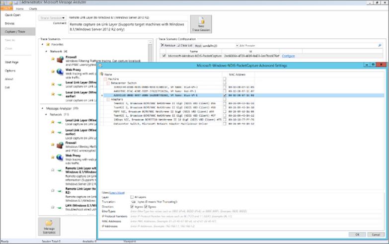
Figure 3.47 Configuring the remote traffic to capture using Message Analyzer
Figure 3.48 shows an example of my captured output from the virtual machine I selected. The ability to remotely monitor specific network adapters, specific virtual switches, and even specific virtual machines with no configuration on the source host is a huge benefit and really completes and emphasizes the capabilities available to us with Windows Server 2012 R2 networking.
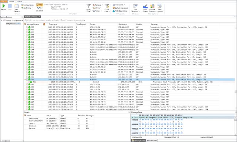
Figure 3.48 Example view of captured traffic
The Bottom Line
1. Architect the right network design for your Hyper-V hosts and virtual machines using the options available. There are many different networking traffic types related to a Hyper-V host, including management, virtual machine, cluster, live migration, and storage. While traditionally separate, network adapters were used with each type of traffic; a preferred approach is to create multiple vNICs in the management partition that connect to a shared virtual switch. This minimizes the number of physical NICs required while providing resiliency from a NIC failure for all workloads connected to the switch.
1. Master It Why are separate network adapters required if SMB is leveraged and the network adapters support RDMA?
2. Identify when to use the types of NVGRE Gateway. There are three separate scenarios supported by NVGRE Gateway: S2S VPN, NAT, and Forwarder. S2S VPN should be used when a virtual network needs to communicate with another network such as a remote network. Forwarder is used when the IP scheme used in the virtual network is routable on the physical fabric, such as, for example, when the physical fabric network is expanded into the virtual network. NAT is required when the IP scheme in the virtual network is not routable on the physical network fabric and requires external connectivity, such as when tenants needed to access the Internet.
3. Leverage SCVMM 2012 R2 for many networking tasks. While Hyper-V Manager enables many networking functions to be performed, each of these configurations are limited to a single host and are hard to manage at scale. SCVMM is focused on enabling the network to be modeled at a physical level, and then the types of network required by virtual environments can be separately modeled with different classifications of connectivity defined. While the initial work may seem daunting, the long-term management and flexibility of a centralized networking environment is a huge benefit.
1. Master It Why is SCVMM required for network virtualization?
All materials on the site are licensed Creative Commons Attribution-Sharealike 3.0 Unported CC BY-SA 3.0 & GNU Free Documentation License (GFDL)
If you are the copyright holder of any material contained on our site and intend to remove it, please contact our site administrator for approval.
© 2016-2026 All site design rights belong to S.Y.A.