Mastering Hyper-V 2012 R2 with System Center and Windows Azure (2014)
Chapter 4. Storage Configurations
In previous chapters, the compute and network resources of a virtual environment were examined, and this chapter deals with the final resource building block—storage. In Windows Server 2012 R2, there are many different storage options and topologies available, enabling organizations to implement different solutions to meet the many different requirements encountered.
Many organizations are familiar with using storage area networks (SANs) as the cornerstone for their storage requirements and leveraging connectivity such as Fibre Channel, and this is still a valid solution, and in certain scenarios, the right architecture. However, with Windows Server 2012, the focus was on choice and offering other storage solutions that can be more cost effective and more flexible, such as iSCSI, SMB 3, and Storage Spaces. Hyper-V fully leverages these technologies in addition to supporting a new virtual hard disk format that offers the highest scalability and performance.
In this chapter, you will learn to
· Explain the types of storage available to a virtual machine
· Identify when to use virtual Fibre Channel vs. Shared VHDX and the benefits of each
· Articulate how SMB 3 can be used
Storage Fundamentals and VHDX
Chapter 2 covered the basics of virtual storage, and I want to quickly review those basics and the various limits and options provided. Nearly every virtual machine scenario will require some kind of “local” storage such as that used to host the boot and system partitions, which contain the operating system environment and locally installed applications and services. Additional storage may also be assigned to the virtual machine for data storage, although this could also be accessed using other network-based methods.
Storage that is assigned to the virtual machine from the host server (in most cases, but there are exceptions, which will be covered later in the book) must first be accessible to the Hyper-V host, such as direct-attached storage to the host or storage that the host can communicate with, such as on a SAN via iSCSI or fibre channel connectivity or even on a Windows file server or network-attached storage (NAS) device using SMB 3 with Windows Server 2012 and above, which introduced file-level access support. It is important that any storage used by the host to store virtual machines is resilient to failure. For direct-attached storage, use technologies to enable a disk to fail without losing data (such as RAID), and for remote-storage, ensure that there are multiple paths to the storage to avoid losing storage access if a single card, cable, or switch fails. The remote storage should also be fault tolerant. When Hyper-V hosts are clustered together, as they always should be to ensure availability of the virtual environment, it's important that storage used by virtual machines is available to all hosts in the cluster.
With storage available at the host level, it needs to be assigned to virtual machines. While it is possible to pass a disk directly from the Hyper-V host into a virtual machine known as a pass-through disk, this is not something that should ever be done, for the following reasons:
· The disk is solely usable by the virtual machine assigned the physical disk from the host so that not even the host can still use the disk.
· Virtual machine checkpoints that provide point-in-time captures of a virtual machine don't work.
· Migration technologies such as Live Migration do not work without an outage to availability.
· Replication technologies such as Hyper-V Replica do not work.
· Virtual machine backup at the host is not possible.
· Storage Quality of Service is not available.
With all of these problems, you may wonder why pass-through storage was even made available as an option, and the answer is that sometimes virtual machines needed access to volumes and storage that was larger or faster than what was possible with the VHD format, which had a 2 TB limit. Consider a large SQL database; a 2 TB limit was too restrictive, and also there was a performance hit when using VHD above the bare-metal storage, especially using dynamic VHD, which grows as data is written to it. In the scenarios in which very large volumes with the highest performance needs were required, the Windows Server 2008 VHD implementation would not suffice, and either pass-through storage had to be used or iSCSI within the VM. Windows 2008 R2 greatly improved the performance of VHD, but the 2 TB limit remained. This is why pass-through was required as an option.
In Windows Server 2012, you should never need pass-through storage. There is not a scenario in which it is required because of the new 64 TB VHDX virtual hard disk format, which also features greatly improved performance effectively matching the bare-metal storage performance. I've never seen a client with an NTFS volume that is 64 TB in size. The largest I have seen is 14 TB because most organizations will limit the size of a NTFS volume in case a volume becomes corrupt and CHKDSK has to be run, although this is no longer a problem with Windows Server 2012 and above.
With the need to use pass-through storage removed, all virtual storage assigned from the Hyper-V host for normal purposes will be through the use of VHDX files. VHD files should only be used if compatibility is required for pre–Windows Server 2012 Hyper-V or Windows Azure (at time of this writing, Windows Azure does not support VHDX but may by the time you read this).
VHDX has other advantages over VHD beyond just performance and scalability:
· Protection against corruption caused by unplanned power outages by logging updates to the VHDX metadata structures.
· Alignment with physical disk structures automatically and 4 KB sector support. Alignment was a big performance problem for early VHD, which was caused by the VHD file geometry, such as virtual sector size, being different from the underlying NTFS file system and disk. Even if the geometry was the same, there may have been an offset between where the VHD started and its header, causing a VHD block to not sit within a single NTFS cluster, which could result in spanning multiple NTFS clusters. This makes disk operations very inefficient because while the virtual OS may think it's fetching a single block, on the physical storage, many different clusters must be read. The good news is that the alignment issue is resolved in VHDX, which will always align correctly. Details can be found in the VHDX specification at the following location:
www.microsoft.com/en-us/download/details.aspx?id=34750
· Custom metadata, allowing management applications to store information such as the OS running inside the VHDX.
· Trim support, which enables the efficient reclaiming of blocks on SSD devices.
What Is the ChkDsk Problem?
ChkDsk is the utility that has to be run when a volume has problems. To fix the problems, the volume has to be taken offline, which means it's unavailable, while a thorough scan and fix is performed on it. The larger the number of files on a volume, the longer the scan for the problems will take and the longer the volume will be offline. For example, a 2 TB volume filled with many files could be offline for hours or days depending on the storage subsystem, which is a long time if the volume contains important data. Therefore, to avoid long outages, organizations would limit the size of NTFS volumes, which reduces the number of files. Think of this scenario as a highway that is closed while a crew walks along looking for potholes and fixing the few that it finds. This road may be closed for weeks or months while the crew is looking for the potholes.
Windows Server 2012 re-architected ChkDsk into a two-phase process. The long process of finding problems now occurs with the volume still online. Once the problems are found, the volume is taken offline and a spotfix of the problems is performed, but in the worst-case scenario, the volume is offline for only 8 seconds and commonly for only milliseconds, which is not noticeable at all. If Cluster Shared Volumes (CSV) is used, there is never downtime because CSV has its own layer of indirection, resulting in just a pause in I/O. Going back to the highway analogy, in Windows Server 2012, the road stays open as the crews hop between cars looking for the problems. Then once they have found all the potholes that are marked on a map, the road is closed for one night while all the found potholes are filled.
To perform the scan, use chkdsk /scan <disk>: or Repair-Volume -Scan <disk>: in PowerShell, and then once the search for problems is complete, perform the spotfix, which will take the volume offline for the maximum of 8 seconds to run the commands chkdsk /spotfix <disk>: or Repair-Volume -SpotFix <disk>:.
This means that NTFS volumes are no longer restricted to a certain size because of fears related to running ChkDsk.
An important point to remember about VHDX is that it is a core part of the operating system for both server and client. VHDX files can be mounted natively to the operating system, and physical machines can even boot from VHDX files, which allows great flexibility for moving an operating system instance from a virtual machine to a physical machine without any real changes being required. If you have a physical system that you would like to convert to a virtual machine, there are a number of technologies available for this physical-to-virtual (P2V) conversion. However, a nice free tool for a small number of conversions is disk2vhd from
http://technet.microsoft.com/en-us/sysinternals/ee656415.aspx
It will take the storage from physical machines and create equivalent VHD and VHDX (version 2) files that could then be used with Hyper-V virtual machines.
Types of Controllers
In Chapter 2 I told you about two types of storage controllers available in a generation 1 virtual machine, IDE and SCSI, while a generation 2 virtual machine supports only the SCSI controller. In a generation 1 virtual machine, the operating system VHDX must be connected to the IDE controller because the SCSI controller does not support bootable devices. In a generation 2 virtual machine, though, the SCSI controller does support bootable devices, allowing the operating system VHDX file to be connected to the SCSI controller.
A generation 1 virtual machine has two IDE controllers, with each controller supporting up to two virtual devices, which could be VHD/VHDX files or virtual DVD drives. Both generation 1 and generation 2 virtual machines support up to four SCSI controllers, with each SCSI controller supporting up to 64 virtual hard disks. Even though the performance of the IDE controller and SCSI controller are equivalent, once the integration services are loaded, the fact that so many more disks are supported on the SCSI controller means that in most environments, the IDE controller is used solely for the operating system storage while all data disks connect to the SCSI controller.
There is one additional difference, or was, between the IDE and SCSI virtual controllers that is important to be aware of and that also makes the SCSI controller a better choice for any kind of database, and that is caching behavior, or more specifically, how write cache is reported. For any kind of database, you typically do not want any kind of write caching on the device. Write caching is a technology that enables storage to report a write has been committed to disk but actually is cached in the controller and will be written in the most optimal way at a later time. The danger with write caching is that if an unplanned outage occurs, the data in the volatile cache would never have been written to the disk and would be lost. This is bad for any kind of database, including Active Directory.
With Hyper-V, write caching cannot be disabled on virtual hard disks because there is no way to ensure that there is not an always-on write cache on the underlying storage or that the VHDX may one day be moved to a disk with an always-on write cache using storage or live migration technologies. Additionally, because many VHDX files can reside on a single physical disk, there is no way to be sure all VHDX files on the physical disk would want the write cache disabled and the configuration of write-cache is a physical disk setting. When the write cache is disabled on a disk that is using Device Manager and is connected to the virtual SCSI controller, an error is displayed, as shown in Figure 4.1. This is important because applications also try to disable write caching, and the error notifying that the write cache could not be disabled allows any application that needs to ensure data write integrity to use alternative methods, specifically Force Unit Access (FUA), to ensure that data is not cached.
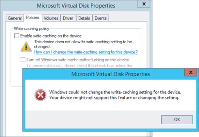
Figure 4.1 An error occurred when the administrator was trying to disable write caching within a virtual machine. Applications would receive a similar error condition.
When applications try to disable write caching on a virtual disk connected to an IDE controller, no error is returned, which makes the application think that write caching has successfully been disabled, so no other actions to ensure data integrity are taken. In reality, though, write caching was not disabled. This can lead to data corruptions in the event of unplanned outages.
Windows Server 2012 R2 does not have this problem, and the good news for Windows Ser-ver 2012 and Windows Server 2008 R2 Hyper-V environments is that Microsoft released a fix, KB2853952. Once this fix is applied to the Hyper-V host, it will correctly return a failure error to the VM if write caching is disabled on the IDE controller, allowing the applications to then leverage FUA.
As you move forward with Windows Server 2012 R2 and generation 2 virtual machines, you don't have many choices to make; you will use a virtual SCSI controller and you will use VHDX files for the best set of features and scalability.
Common VHDX Maintenance Actions
In Chapter 2 I covered basic commands to create VHDX files and also the basic Edit Disk actions that allow certain modifications and optimizations to be performed. I will go into some additional details in this section.
First, as mentioned, a VHDX file can be natively mounted in Windows Server by right-clicking it and selecting the Mount option or just double-clicking the file. To unmount, right-click the volume in Explorer and choose Eject. This can also be performed using the various disk management tools, but for automation, scripting the mount and unmounts can be very useful. PowerShell provides an easy way to mount and unmount a VHDX file:
Mount-VHD -Path D:\Virtuals\newdyn.vhdx
Dismount-VHD -Path D:\Virtuals\newdyn.vhdx
Throughout this chapter I talk about VHDX, but many environments will have VHD files from previous deployments and you might want to convert them to VHDX to gain the new capabilities. Using Hyper-V Manager, start the Edit Disk action and select the source VHD file. Then under the action, select Convert and then select the VHDX format, which will convert the VHD to a VHDX file. This can also be done using PowerShell:
Convert-VHD -Path d:\temp\source.vhd -DestinationPath d:\temp\destination.vhdx
Note that any conversion process creates a new virtual hard disk file and copies the content across, which means you need sufficient free space to create the temporary new file until the old file is deleted. It is also possible to convert a VHDX to a VHD file using the same process providing the VHDX is less than 2,040 GB in size.
Dynamic VHDX files will grow as writes are performed, but they never shrink automatically, even if large amounts of data are deleted. This means that if you delete a large amount of data from a dynamic VHDX file and want to reclaim the space on the physical disk, you need to perform a compaction of the VHDX file, which can be performed by using the Hyper-V Manager Edit Disk action and selecting the Compact action. This can also be performed using PowerShell:
Optimize-VHD -Path d:\temp\data1.vhdx
There are optional parameters that can be used with Optimize-VHD that tune the type of optimization and are fully explained at
http://technet.microsoft.com/en-us/library/hh848458.aspx
However, in most cases the default optimization mode of Quick for a VHDX will yield the desired result.
When a VHDX file is created, it can be created as a fixed or dynamic VHDX file. This can be changed through the Edit Disk action or through PowerShell Convert-VHD, specifying the -VHDType parameter as Fixed or Dynamic.
The size of a VHDX file can also be changed using the same method, increasing the available space or even shrinking it, provided there is sufficient unallocated space on the disk inside the virtual machine. For example, if a VHDX file is 80 GB but the virtual machine inside has only allocated 60 GB of storage, it would leave 20 GB unallocated, as shown in Figure 4.2. This would allow the VHDX file to be shrunk by 20 GB. This can be confirmed when looking at the properties of a VHDX file and inspecting the MinimumSize attribute. Note that when working with dynamic disks, changing the size of the file changes only its maximum size; the actual amount of space used on disk is based entirely on the data written, which is shown in the FileSize attribute. If you wanted to reduce the size of a VHDX file more than the MinimumSize attribute, you should connect to the virtual machine and shrink the size of the volumes inside the virtual machine using Disk Management to increase the amount of unallocated space.
PS E:\Virtuals\win81nondomain\Virtual Hard Disks> Get-VHD .\win81nondomain.vhdx
ComputerName : SAVDALHV01
Path : E:\Virtuals\win81nondomain\Virtual Hard Disks\win81nondomain.vhdx
VhdFormat : VHDX
VhdType : Dynamic
FileSize : 11983126528
Size : 85899345920
MinimumSize : 64423477760
LogicalSectorSize : 512
PhysicalSectorSize : 4096
BlockSize : 33554432
ParentPath :
DiskIdentifier : ae420626-f01e-4dfa-a0a5-468ffdfe95ad
FragmentationPercentage : 6
Alignment : 1
Attached : True
DiskNumber :
Key :
IsDeleted : False
Number :
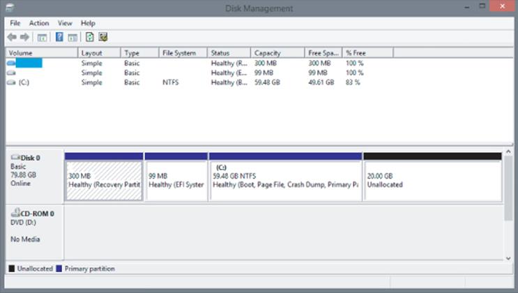
Figure 4.2 A virtual machine with 20 GB of space unallocated
Performing Dynamic VHDX Resize
Prior to Windows Server 2012 R2, any changes to the size of a VHDX file required the virtual machine using the VHDX file to be shut down. There was no way to dynamically resize a VHDX while the virtual machine was still running, which some organizations found to be a pain point. Windows Server 2012 R2 introduces dynamic resize for both increasing and decreasing the size of a file. The requirements for dynamic resize are as follows:
· Must be a VHDX file. Dynamic resize is not supported for VHD files.
· Must be connected to the SCSI controller. Dynamic resize is not supported for virtual hard disks connected to the IDE controller.
Performing a dynamic resize is exactly the same as performing an offline resize operation:
1. Within Hyper-V Manager, select the Edit Disk option.
2. Click Next on the Edit Virtual Hard Disk Wizard introduction page.
3. Select the VHDX file to modify (remember, the VM using it can still be running), and then click Next.
4. Select the Expand or Shrink option, depending on your desired action, and then click Next.
5. If you selected Shrink, the minimum possible size will be shown in brackets. If you selected Expand, the maximum possible size will be shown in brackets. Enter the new size and click Next.
6. Click Finish to perform the resize.
If you performed an expand of a virtual hard disk within the virtual machine, you need to use the newly available unallocated disk space. Either extend an existing volume or create a new volume in the unallocated space using the Disk Management MMC snap-in or PowerShell. If a shrink was performed, no actions are required; there will simply be less or no unallocated space on the disk.
To resize using PowerShell, utilize the Resize-VHD cmdlet, passing the new size using the -SizeBytes parameter (however, you do not have to type the size in bytes; you can type numbers such as 2 GB or 10 TB), which can be less or more than the current size, as long as it is a valid size (i.e., not smaller than the MinimumSize attribute and not larger than VHDX 64 TB limit or than is physically available if it is a fixed-size VHDX file). If you want to shrink the file as much as possible, instead of using -SizeBytes, use the -ToMinimumSizeparameter, as in this example:
Resize-VHD .\win81nondomain.vhdx -ToMinimumSize
Storage Spaces and Windows as a Storage Solution
While not strictly a Hyper-V topic, I want to briefly cover the big shift in storage introduced with Windows Server 2012 because it will most likely affect the way your Hyper-V environments are architected, especially in smaller organizations and branch offices.
In the introduction I talked about Fibre Channel– and iSCSI-connected storage area networks, which historically have been the preferred storage choice for organizations because they provide many benefits:
· Storage is centralized, allowing the highest utilization of the available space as opposed to many separate instances of storage with lots of wasted space.
· Centralized backup is possible.
· They offer the highest level of performance and scalability, which is possible because the storage is all centralized, allowing higher-specification storage solutions to be purchased.
· Storage is accessible to all servers throughout the datacenter, providing the server has the required connectivity, such as fibre channel or iSCSI.
· Centralized storage enables easy migration of virtual machines between physical hosts because the storage can be seen by multiple servers.
· They provide shared storage, which is required for many cluster scenarios.
The use of high-end, centralized storage is still a great option for many organizations and scenarios. However, there is also another model being adopted by many organizations and service providers, including Windows Azure, which is the move from centralized storage to the use of just a bunch of disks (JBOD) solutions that are either local to a server or in an external enclosure connected to a number of clustered hosts. This can provide great cost efficiencies because storage subsystems based on regular disks are much cheaper than SAN solutions. It is important, though, to build in resiliency and backup solutions for what is now local storage containing critical workloads, that is, your virtual machines.
Windows Server has long had the ability to create fault resilient storage using Redundant Array of Independent Disks (RAID) technology in one of two modes: RAID-1, which mirrored all data from one disk to another disk, and RAID-5, which used striping with parity. However, there were challenges with the software RAID implementation:
· It did not self-heal. If a disk was lost, another disk had to be manually configured to be the replacement.
· Only thick/fat provisioning was possible, which means a volume can be created only up to the physical space available. Thin provisioning, which allows volumes to be created beyond the physical space and allocated as data was written, was not possible.
· Management was quite painful, and RAID volumes could not be resized easily.
· Was not supported in a Failover Cluster.
Storage Spaces was introduced in Windows Server 2012 as a completely new way to think about managing and using direct attached storage. With Storage Spaces, the physical disks that are providing the underlying storage of data are completely abstracted from the process of requesting new volumes, now known as spaces, and any actions required to restore data redundancy in the event of a disk failure are performed automatically by the Storage Spaces technology as long as there are sufficient physical disks available.
The first step is to create a storage pool, which is a selection of one or more physical disks that are then pooled together and can be used by the Storage Spaces technology. Supported disk types in a storage pool are USB, SATA, and SAS connected disks. These disks are just standard disks, JBOD. With no hardware high availability such as RAID behind the scenes, Storage Spaces is going to take care of fault tolerance. The use of USB-connected drives is great on the desktop side, while servers will focus on SATA and SAS connected drives. Additionally, shared SAS is fully supported, which means a disk enclosure could be used that is then connected to a number of hosts in a cluster and the storage space created on those shared SAS drives would be available to all nodes in the cluster and can be used as part of Cluster Shared Volumes. This allows a cluster of Hyper-V hosts to use a clustered storage space as the storage for virtual machines. If an external disk enclosure is used, Storage Spaces supports the SES protocol, which enables failure indications on the external storage if available, such as a bad disk LED in the event Storage Spaces detects a problem with a physical disk. While there are many storage enclosures that work with clustered storage spaces, Microsoft does have a number certified enclosures for Windows Server 2012, which are documented at the Windows Server Catalog.
Other technologies, like BitLocker, can also be used with Storage Spaces. When a new storage pool is created, the disks that are added to the storage pool will disappear from the Disk Management tool because they are now virtualized and used exclusively by the Storage Spaces technology. The disks' state can be seen through the Storage Pools view within File and Storage Services in Server Manager. To create a storage pool, follow these steps:
1. From the Tasks menu, select New Storage Pool, which launches the New Storage Pool Wizard.
2. Enter a name for the new storage pool and an optional description and click Next.
3. On the next screen, select the physical disks that are available to be added to the new pool and their allocation. The default allocation for disks will be Data Store to be used as part of virtual disks created but can also be reserved for Hot Spare purposes. Click Next
4. Once the confirmation is displayed, click Create to create the storage pool.
A storage pool is now available, and the next step is to create virtual disks within the storage pool, which can then have volumes created on them to be used by the operating system. The nomenclature is unfortunate here. While the term virtual disk is used by Storage Spaces, it is not a virtual hard disk of any kind and does not leverage VHD or VHDX. A virtual disk is simply an object created within a storage pool that is seen as a disk by the operating system, which writes directly to blocks within the storage pool.
Storage Spaces introduces a feature that was previously only available using external storage solutions such as SANs and NAS devices, the ability to thin provision storage. During the creation of a virtual disk, the option is available to create the new virtual disk as fixed, which means all the space for the size of the virtual disk is allocated at creation time, or thin, which means space is taken from the pool only as needed. Using a thin provisioned disk would allow a virtual disk to be created far larger than the actual storage available. This allows you to create a large volume initially without having to preallocate physical storage.
Now, this does not mean you can store more data in the thinly provisioned disk than actually is allocated to the pool but that typically volumes fill up over time. I may create a 10 TB thin disk that initially only has 1 TB of physical storage associated with it, but as the amount data increases and approaches 1 TB, I would add another 1 TB of physical storage to the pool by just adding more disks. As it approaches 2 TB, I add another 1 TB of storage by adding more disks and so on. As long as I add physical disks before it fills, there is no issue. Alerts will be generated notifying me that a storage pool is reaching the threshold, giving me time to add the required storage. When a virtual disk is created, all that needs to be known is which storage pool to create the disk in. No knowledge of physical disks is required or even openly available. The point of storage spaces is this abstraction to just create virtual disks as needed to suit what is required. To create a virtual disk, perform the following steps:
1. Select a storage pool in which to create a new virtual disk, and in the Virtual Disks section, select the New Virtual Disk task.
2. Confirm the correct server and storage pool is selected in the Storage Pool selection page of the wizard and click Next.
3. Give a name and optional description for the new virtual disk and then click Next.
4. Select the storage layout. The options are Simple (no data redundancy and data striped over many disks), Mirrored (data duplicated to additional disks), and Parity (spreads data over multiple disk like Simple but adds parity data so in the event of a disk loss, no data is lost). Prior to Storage Spaces, these layouts would have been referred to as RAID-0, RAID-1, and RAID-5, respectively, but that nomenclature is not used with Storage Spaces layouts due to differences in implementation.
Make the selection and click Next. This is shown in Figure 4.3. A three-way mirror is possible in Windows Server 2012 and beyond, but it must be configured using PowerShell instead of the graphical interface.
5. Choose a provisioning type of Thin or Fixed, and click Next.
6. Specify a size. Remember, if Thin was selected, a size larger than the physical free space available can be selected. Click Next.
7. A confirmation of options will be displayed. Confirm them and click Create.
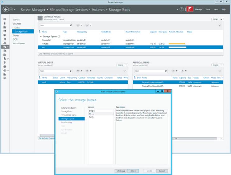
Figure 4.3 Creating a new virtual disk within a storage space
Once the virtual disk is created, it will be available within Server Manager and the Disk Management MMC to create volumes and be formatted with a file system. The actual amount of space used from a pool can be seen in Server Manager or, if you're using a client, in the Storage Spaces Control Panel applet.
Performance and Storage Spaces
One concern I always had when using software RAID prior to Windows Server 2012 was performance because any parity calculation had to use the processor, which used up processor cycles and typically was just not optimal compared to a hardware RAID solution. This is still a concern with Storage Spaces.
Fundamentally, Storage Spaces is a software-implemented storage solution. This means that, when using any kind of parity virtual disk, it is the operating system, specifically the processor, that has to calculate the parity information. Using a parity resiliency will utilize additional processor resources. In my experience, parity utilizes only a single processor core and therefore can quickly become a bottleneck if you are performing large amounts of disk writes, making it unsuitable for some workloads. Therefore, my advice is as follows:
· Use mirroring for workloads requiring high performance.
· Use parity for archival and media streaming purposes where there are not performance-critical write operations.
Windows Server 2012 R2 Storage Spaces has a number of improvements, including the ability to have dual-parity spaces, which allows up to two copies of parity information instead of one. That provides additional resiliency (dual parity needs to be configured using PowerShell and is not exposed in Server Manager), support for parity spaces in cluster scenarios, and much faster rebuild in the event of a failure by rebuilding the missing information to many disks in the storage pool instead of rebuilding everything to a single disk, which limits the speed of resolution to the IOPS possible by a single disk.
There was a bigger change in Windows Server 2012 R2 Storage Spaces that can open up new levels of performance and that is the differentiation between traditional spinning hard disk drives (HDDs) and solid-state drives (SSDs). In a Windows Server 2012 R2 storage space, it is possible to create different tiers of storage, an HDD tier and a SSD tier, and the Storage Spaces technology will move the most-used blocks of a file from the HDD tier into the SSD tier, giving the highest levels of performance. Additionally, the SSD tier can be leveraged for a write-back cache. This means that as writes occur, they are written into the SSD tier initially, which is very fast, and then lazily written to the HDD tier for long-term storage. This new tiering model is shown in Figure 4.4. When you use tiering, you must have a sufficient number of disks from each tier to meet the data resiliency options. For example, if mirroring is selected for a virtual disk, at least two disks would need to be available with enough space in the HDD tier and in the SSD tier. The same applies for the write-back cache. Storage Spaces will not allow a drop in resiliency.
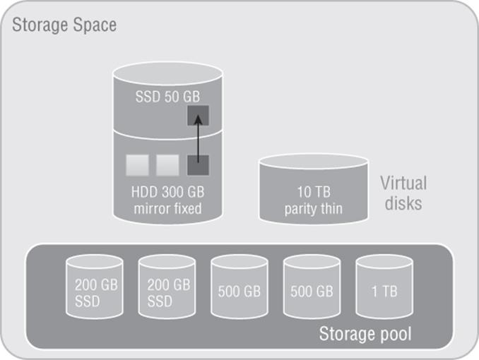
Figure 4.4 Storage Spaces architecture showing a hot block moving from the HDD tier to the SSD tier
To utilize tiering and the write-back cache you can use PowerShell, which gives granular control (although by default a 1 GB write-back cache is created on all new virtual disks if sufficient SSD space and disks are available in the pool), or Server Manager for a simpler experience but with less granularity in the configuration. In the following PowerShell commands, I create a storage space from four physical disks, two HDDs and two SSDs, and then create a virtual disk and create a volume:
#List all disks that can be pooled and output in table format (format-table)
Get-PhysicalDisk -CanPool $True | ´
ft FriendlyName,OperationalStatus,Size,MediaType
#Store all physical disks that can be pooled into a variable, $pd
$pd = (Get-PhysicalDisk -CanPool $True | Where MediaType -NE UnSpecified)
#Create a new Storage Pool using the disks in variable $pd
#with a name of My Storage Pool
New-StoragePool -PhysicalDisks $pd ´
–StorageSubSystemFriendlyName "Storage Spaces*" ´
-FriendlyName "My Storage Pool"
#View the disks in the Storage Pool just created
Get-StoragePool -FriendlyName "My Storage Pool" | ´
Get-PhysicalDisk | Select FriendlyName, MediaType
#Create two tiers in the Storage Pool created.
#One for SSD disks and one for HDD disks
$ssd_Tier = New-StorageTier -StoragePoolFriendlyName "My Storage Pool" ´
-FriendlyName SSD_Tier -MediaType SSD
$hdd_Tier = New-StorageTier -StoragePoolFriendlyName "My Storage Pool" ´
-FriendlyName HDD_Tier -MediaType HDD
#Create a new virtual disk in the pool with a name of TieredSpace
#using the SSD (50GB) and HDD (300GB) tiers
$vd1 = New-VirtualDisk -StoragePoolFriendlyName "My Storage Pool" ´
-FriendlyName TieredSpace -StorageTiers @($ssd_tier, $hdd_tier) ´
-StorageTierSizes @(50GB, 300GB) -ResiliencySettingName Mirror ´
-WriteCacheSize 1GB
#cannot also specify -size if using tiers and also
#cannot use provisioning type, e.g. Thin
Normally the hot blocks are detected over time and moved into the SSD tier as part of a nightly optimization job at 1:00 a.m. However, certain files can be pinned to the SSD tier, which will keep them there permanently. To pin a file to the SSD tier and then force a tier optimization, use the following commands:
Set-FileStorageTier –FilePath M:\Important\test.vhd ´
-DesiredStorageTier ($vd1 | Get-StorageTier –MediaType SSD)
Optimize-Volume –DriveLetter M –TierOptimize
With Storage Spaces technology, you can create flexible and performant storage solutions using direct attached disks, which can be useful in a number of scenarios and architectures. I walk through Storage Spaces in a video at
www.youtube.com/watch?v=x8KlY-aP9oE&feature=share&list=UUpIn7ox7j7bH_OFj7tYouOQ
The use of tiering is a great feature for virtualization and will help you get the highest overall performance without having to use high-end storage for the entire storage solution.
Server Message Block (SMB) Usage
While SMB has been available in Windows for a very long time, its usage has been limited to basic file sharing scenarios such as users accessing their home drives or a file share containing some archived data. Hyper-V had long had the requirement of having block-level access to its storage; that is, the host mounted the volumes that contained the virtual machines, which could be direct attached or connected via mediums such as iSCSI or Fibre Channel. However, this was a challenge for many organization that were used to using file-level protocols with virtualization. Specifically, VMware supported NFS for virtual machine storage, which was available in many NAS solutions that typically are much cheaper than SAN solutions and are a good fit for many environments.
Windows Server 2012 invested greatly in SMB to make it an enterprise-ready solution suitable for storing virtual machines and other enterprise workloads, such as SQL Server databases. SMB 3.0 introduced a large number of new features and performance improvements to make it a realistic choice for virtualization storage.
SMB Technologies
I previously talked about SMB being used to store user documents, and now with SMB 3.0, it will be used to store mission-critical virtual machines. This requires a big shift in resiliency and failover technologies. When the user is editing their PowerPoint document from a SMB share, portions of the document are cached locally and occasionally the user clicks Save. If the SMB file server experiences a problem—for example, if it reboots or if it's clustered and the file share is moved to another node in the cluster—the user would lose their handle and lock to the file, but that really does not have any impact. The next time the user clicks Save, everything is reestablished and no harm is done. Now consider Hyper-V storing a virtual machine on a SMB file share that experiences a problem and the file share moves to another node in the cluster. First, the Hyper-V box will wait for the TCP time-out before realizing the original connection has gone, which can mean 30 seconds of pause to the VM, but also Hyper-V has now lost its handles and locks on the VHD, which is a major problem. Where user documents may be used for a few hours, enterprise services like a virtual machine or database expect handles on files to be available for months without interruption.
SMB Transparent Failover
Typically for a clustered file service, a single node of the cluster mounts the LUN containing the file system being shared and offers the share to SMB clients. If that node fails, another node in the cluster mounts the LUN and offers the file share but the SMB client would lose their handles and locks. SMB Transparent Failover provides protection from a node failure, enabling a share to move between nodes in a manner completely transparent to the SMB clients and maintaining any locks and handles that exist and also the state of the SMB connection.
The state of that a SMB connection is maintained over three entities: the SMB client, the SMB server, and the disk itself that holds the data. SMB Transparent Failover ensures that there is enough context to bring back the state of the SMB connection to an alternate node in the event of a node failure, which allows SMB activities to continue without the risk of error.
It's important to understand that even with SMB Transparent Failover there can still be a pause to IO because the LUN still has to be mounted on a new node in the cluster. However, the failover clustering team has done a huge amount of work around optimizing the dismount and mount of a LUN to ensure that it never takes more than 25 seconds, which sounds like a lot of time, but realize that is the absolute worst-case scenario with large numbers of LUNs and tens of thousands of handles. For most common scenarios, the time would be a couple of seconds, and enterprise services such as Hyper-V and SQL Server can handle an IO operation taking up to 25 seconds without error in that worst possible case.
There is another cause of a possible interruption to IO and that's the SMB client actually noticing that the SMB server is not available. In a typical planned scenario such as a node rebooting because it's being patched, it will notify any clients who can then take actions. If a node crashes, though, there is no notification to the client and so the client will sit and wait for TCP time-out before it takes action to reestablish connectivity, which is a waste of resources. Although a SMB client may have no idea that the node it's talking to in the cluster has crashed, the other nodes in the cluster know within a second thanks to the various IsAlive messages that are sent between the nodes. This knowledge is leveraged by a new witness service capability that is available in Windows Server 2012. The witness server essentially allows another node in the cluster to act as a witness for the SMB client, and if the node the client is talking to fails, the witness node notifies the SMB client straight away, allowing the client to connect to another node, which minimizes the interruption to service to a couple of seconds. When a SMB client communicates to a SMB server that is part of a cluster, the SMB server will notify the client that other servers are available in the cluster and the client will automatically ask one of the other servers in the cluster to act as the witness service for the connection.
There is no manual action required to take advantage of SMB Transparent Failover or the witness service. When you create a new share on a Windows Server 2012 or above failover cluster, SMB Transparent Failover is enabled automatically.
SMB Scale-Out
In the previous section, I explained that there would be a pause in activity because the LUN had to be moved between nodes in the file server cluster, but this delay can be removed. This problem stems from the fact that NTFS is a shared-nothing file system and cannot be accessed by multiple operating system instances concurrently without the risk of corruption. This problem was solved with the introduction of Cluster Shared Volumes (CSV) in Windows Server 2008 R2. CSV allowed all nodes in a cluster to read and write to the same set of LUNs simultaneously using some very clever techniques, thus removing the need to dismount and mount LUNs between the nodes.
Windows Server 2012 extends the use of CSV to a specific type of file server, namely the Scale-Out File Server option, which is a new option available in Windows Server 2012 and targeted for use only when sharing out application data such as SQL Server databases and Hyper-V virtual machines. The traditional style of the general-use file server is still available for non-application data, as shown in Figure 4.5. When selecting the option to create a scale-out file server (SoFS), you must select a CSV as the storage when shares are subsequently created within the file server; the storage is therefore available to all nodes in the cluster. Because the storage for the share is available to all nodes in the cluster, the file share itself is also hosted by all the nodes in the cluster, which now means SMB client connections are distributed over all the nodes instead of just one. In addition, if a node fails, there is now no work involved in moving the LUNs, offering an even better experience and reducing any interruption in operations to almost zero, which is critical for the application server workloads to which this scale-out file server is targeted.
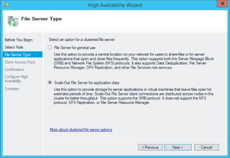
Figure 4.5 Enabling active-active through the selection of Scale-Out File Server For Application Data
The use of scale-out file servers offers an additional benefit. Typically, when a general-use file server is created as part of the configuration, you have to give the new cluster file server a NetBIOS name and also its own unique IP address because that IP address has to be hosted by whichever node in the cluster is currently hosting the file server. With scale-out file servers, all nodes in the cluster offer the file service, which means no additional IP addresses are required. The IP addresses of the nodes in the cluster are utilized via the Distributed Network Name (DNN) that is configured.
All the nodes in the cluster are offering the same file service and therefore share with the scale-out file server, and there is a change in functionality between Windows Server 2012 and Windows Server 2012 R2. In Windows Server 2012, a single SMB client will only ever connect to one of the nodes in the cluster simultaneously even if establishing multiple connections. Essentially, when the SMB client initiates connections, it will initially get a list of all the IP addresses for the hosts in the cluster and pick one of them to initiate the SMB session with. It will then use only that node unless that node experiences a problem, in which case it will converse with an alternate node. The exception is that the SMB client does communicate with a second node when leveraging the witness service I previously discussed. Windows Server 2012 R2 introduces a rebalancing feature that will has two components:
· The CSV disk ownerships are distributed evenly between all nodes in the cluster, spreading the workload.
· SMB connections are rebalanced so clients are directed to the CSV owner, giving the most optimal connection when used with clustered Storage Spaces (this rebalancing is not required when using symmetrical storage such as a Fibre Channel connected SANs because every node has equivalent connectivity).
This means that a single SMB client could now be connected to multiple nodes in a cluster via SMB instead of a single node.
SMB Multichannel
It is critical to avoid any single points of failure in any solution, and if SMB is being used to access the storage containing virtual machines, there must be resiliency to prevent a single network adapter, network cable, or network switch from failing. In storage fabrics, technologies such as Multi-Path I/O (MPIO) are used to provide multiple paths to storage, and this same idea is now possible with SMB using SMB Multichannel.
SMB Multichannel allows a SMB client to establish multiple connections for a single session, providing protection from a single connection failure and also adding additional performance. As with most of the SMB 3.0 features, there are no manual steps to utilize SMB Multichannel; it happens automatically. Once the initial SMB connection has been established, the SMB client looks for additional paths to the SMB server, and where multiple network connections are present, those additional paths are utilized. This would be apparent if you're monitoring a file copy operation as initially only a single connection's worth of bandwidth. However, the bandwidth would double as the second connection was established and the bandwidth aggregated, then the third connection, and so on. In the event a connection fails, there are still other connections to continue the SMB channel without interruption.
To see whether SMB Multichannel is being utilized from your server, use the Get-SMBConnection PowerShell cmdlet, which will show the SMB connections to a SMB share. In the following example, I see that I have only two connections to my server:
PS C:\> get-smbconnection
ServerName ShareName UserName Credential Dialect NumOpens
---------- --------- -------- ---------- ------- --------
savdalsofs.sav… Virtuals NT VIRTUAL … SAVILLTECH.N… 3.02 4
savdalsofs.sav… Virtuals SAVILLTECH\… SAVILLTECH.N… 3.02 2
If I run the Get-SmbMultiChannelConnection cmdlet from the client, it shows me all the possible paths that the server can accept connections over, as shown in the following output. Note that on the server side, networking uses a NIC team, which means only one IP address but can still leverage SMB Multichannel.
PS C:\> get-smbmultichannelconnection
Server Name Selected Client IP Server IP Client Server Client RSS Client RDMA
Interface Interface Capable Capable
Index Index
----------- -------- --------- --------- ------- -------------- -------------- --------------
savdalsofs.... True 10.7.173.101 10.7.173.20 14 15 True False
savdalsofs.... True 10.7.173.23 10.7.173.20 15 15 True False
To confirm which path is actually being used between the client and the server, I can look at the TCP connections to the remote port 445, which is used for SMB. This confirms that I am using the two available paths with four connections for each path (which is the default number).
PS C:\> Get-NetTCPConnection -RemotePort 445
LocalAddress LocalPort RemoteAddress RemotePort State AppliedSetting
------------ --------- ------------- ---------- ----- --------------
10.7.173.23 56368 10.7.173.20 445 Established Datacenter
10.7.173.23 49826 10.7.173.20 445 Established Datacenter
10.7.173.23 49825 10.7.173.20 445 Established Datacenter
10.7.173.23 49824 10.7.173.20 445 Established Datacenter
10.7.173.101 49823 10.7.173.20 445 Established Datacenter
10.7.173.101 49822 10.7.173.20 445 Established Datacenter
10.7.173.101 49821 10.7.173.20 445 Established Datacenter
10.7.173.101 49820 10.7.173.20 445 Established Datacenter
SMB Direct
While there are a number of other SMB technologies, such as encryption, Receive Side Scaling, VSS for SMB File Shares, and more, the last feature I want to mention is SMB Direct, which enables the use of RDMA-capable network adapters with SMB. I discussed remote direct memory access (RDMA) in the Chapter 3 as it relates to network adapters, and it's is equally important to SMB.
With SMB Direct leveraging the RDMA capability of the network adapter, there is almost no utilization of server processor resources. The network adapter is essentially pointed to a block of memory containing the data that needs to be sent to the target, and then the card takes care of sending it using the fastest possible speed with very low latencies. Behind the scenes, the RDMA network adapter may use iWARP, RDMA over Converged Ethernet (RoCE), or InfiniBand, but that does not matter to the SMB protocol, which just benefits from the RDMA capability.
There is no special requirement to leverage SMB Direct. Like everything else with SMB, if the capability exists, it just happens. Initially, a regular SMB connection is established between the client and server. A list of all possible connections is found, which enables the use of multi-channel, and then the capabilities of the network adapters are found. If it is found that both the sender and receiver support RDMA, then a RDMA connection is established and SMB operations switch from TCP to RDMA, completely transparently.
If you used SMB Direct in Windows Server 2012, you will see a 50 percent performance improvement using the SMB Direct v2 in Windows Server 2012 R2 for small IO workloads, specifically 8 KB IOPs, which are common in virtualization scenarios.
The performance improvement is important because SMB is leveraged for more than just file operations now. SMB is also used by Live Migration in some configurations, specifically to take advantage of RDMA-capable NICs. Remember, do not use NIC Teaming with RDMA-capable network adapters because NIC Teaming blocks the use of RDMA.
How to Leverage SMB 3 in Your Environment
If right now your datacenter has every virtualization host connected to your top-of-the-line SAN using Fibre Channel, then most likely SMB 3 will not factor into that environment today. However, if not every server is connected to the SAN or you have new environments such as datacenters or remote locations that don't have a SAN or that will have a SAN but you want to try to minimize the fabric costs of Fibre Channel cards and switches, SMB 3 can help.
If you already have a SAN but do not currently have the infrastructure (for example, the HBAs) to connect every host to the SAN, then a great option is shown in Figure 4.6. A scale-out file server cluster is placed in front of the SAN, which provides access to the SAN storage via SMB 3. This allows the investment in the SAN and its capabilities to be leveraged by the entire datacenter without requiring all the hosts to be connected directly to the SAN. To ensure best performance, have at least as many CSV volumes as nodes in the cluster to allow the balancing to take place. Have double or triple the number of CSV volumes for even better tuning. For example, if I have four hosts in the SoFS cluster, then I would want at least eight CSV volumes.
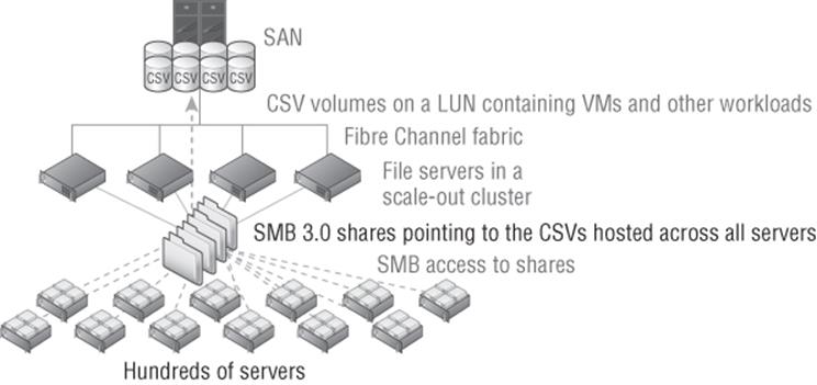
Figure 4.6 Using a scale-out file server in front of a SAN
Another option if you do not have a SAN or don't want to use it for certain workloads is to leverage Storage Spaces as the backend storage. While it would be possible to have a single server using Storage Spaces and hosting storage via SMB 3 to remote hosts, this would be a poor design because it introduces a single point of failure. If the SMB 3 server was unavailable, every workload hosted on the server would be unavailable as well. Always leverage a file server cluster and use a clustered storage space, which would have the disks stored in an external enclosure and be accessible to all the nodes in the cluster that are connected. Ensure that resiliency is enabled for the virtual disks created, most likely mirroring for best performance. This would look like Figure 4.7.
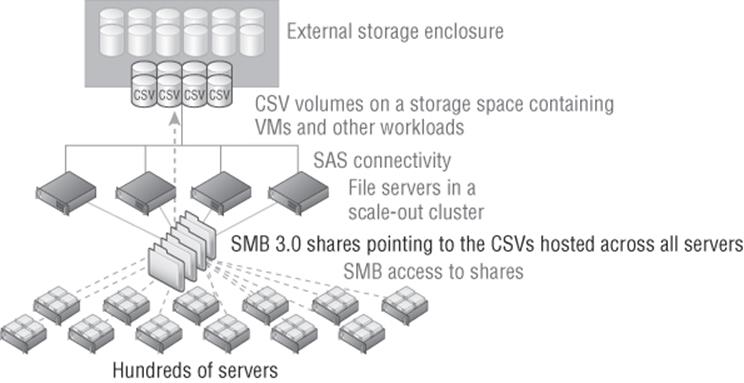
Figure 4.7 Using a scale-out file server and a clustered storage space
Using SMB for Hyper-V Storage
Using SMB 3 with Hyper-V is easy. The Hyper-V host's computer account and the cluster account (if hosts are in a cluster) requires full control at the share and NTFS file system level. Additionally, the administrator creating or moving the virtual machines should have full control at the share and NTFS level. The easiest way to set the correct permissions is using PowerShell, which is simple in Windows Server 2012 R2. This could also be done through Failover Cluster Manager on shares created on scale-out file servers. The following command creates a folder and then gives the computer accounts for Hyper-V hosts HV01 and HV02 full control and the HVCLUS account for the failover cluster they are in full control as well. Note the $ after the computer account names, which must be typed. Additionally the administrator is given full control.
MD G:\VMStore
New-SmbShare -Name VMStore -Path G:\VMStore '
-FullAccess domain\administrator, '
domain\HV01$, domain\HV02$, domain\HVCLUS$
Set-SmbPathAcl -Name VMStore
Note that in Windows Server 2012, the Set-SmbPathAcl cmdlet was not available and the NTFS permissions had to be set manually, as shown in the following command. Note this is not required in Windows Server 2012 R2 because the Set-SmbPathAcl cmdlet copied the share permissions to the NTFS file system.
ICACLS G:\VMStore /Inheritance:R
ICACLS G:\VMStore /Grant ' "domain\administrator:(CI)(OI)F"
ICACLS G:\VMStore /Grant domain\HV01$:(CI)(OI)F
ICACLS G:\VMStore /Grant domain\HV02$:(CI)(OI)F
ICACLS G:\VMStore /Grant domain\HVCLUS$:(CI)(OI)F
Once the permissions are correctly set, simply specify the SMB share as the location for VM creation or as the target of a storage migration. Figure 4.8 shows a virtual machine using the share \\savdalsofs\Virtuals for its storage. Note that not only is the disk stored on the share, but also the configuration files, checkpoint files, and smart paging files. It's actually possible to use different storage locations for the different assets of a virtual machine.
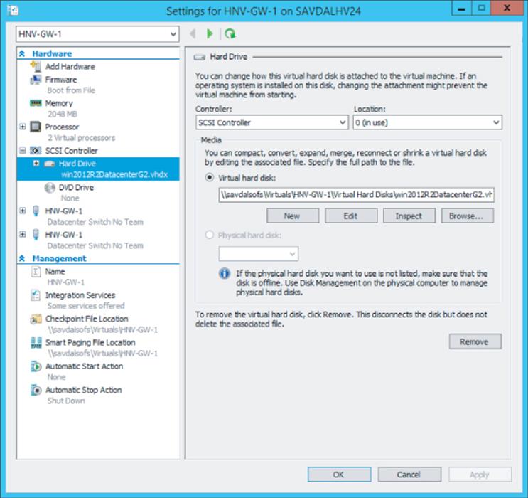
Figure 4.8 A virtual machine using SMB for its storage
iSCSI with Hyper-V
Previously I talked about assigning storage to the virtual machine in the form of a virtual hard disk, which required the Hyper-V host to connect to the storage and then create the VHDX files on it. There are, however, other ways to present storage to virtual machines.
iSCSI is a popular alternative to fibre channel connectivity that allows block-level connectivity to SAN storage using the existing network infrastructure instead of requiring a completely separate fabric (cards, cables, switches) just for storage. iSCSI works by carrying the traditional SCSI commands over IP networks. While it is possible to run iSCSI over the existing network infrastructure, if iSCSI is being used as the primary storage transport, it is common to have a dedicated network connection for iSCSI to ensure the required bandwidth or, ideally, to leverage larger network connections such as 10 Gbps and use QoS to ensure that iSCSI gets the required amount of bandwidth.
In addition to using iSCSI on the Hyper-V host to access storage, it can also be leveraged within virtual machines as a means to provide storage that is accessible to the virtual machine including providing storage that could be accessed by multiple virtual machines concurrently, known as shared storage, and is required in many cluster scenarios in which clusters are implemented within virtual machines, known as guest clustering. If you intend to leverage iSCSI within virtual machines, it is a good idea to have dedicated networking for iSCSI, which means creating a separate virtual switch on the Hyper-V hosts connected to the adapters allocated for iSCSI and then creating an additional network adapter in the virtual machines connected to the virtual switch. If the iSCSI communication is important to the business, you may want to implement redundant connectivity, which can be accomplished by creating multiple virtual switches connected to different network adapters, creating multiple virtual network adapters in the virtual machines (connected to the different virtual switches), and then using MPIO within the virtual machine. I will talk more about MPIO in the section “Understanding Virtual Fibre Channel.” Do not use NIC Teaming with iSCSI because it's not supported, except in one scenario.
If you have a shared NIC scenario (as discussed in Chapter 3), which uses a number of separate network adapters that are teamed together using the Windows Server NIC Teaming solution (it must be the Windows in-box NIC Teaming solution) and the NIC team then has multiple virtual network adapters created at the host level for different purposes, one of which is for iSCSI, NIC Teaming is supported. But this is the only time it can be used with iSCSI. If you had dedicated network adapters for iSCSI, then use MPIO.
There are two parts to iSCSI: the iSCSI Initiator, which is the client software that allows connectivity to iSCSI storage, and the iSCSI target, which is the server software. The iSCSI Initiator has been a built-in component of Windows since Windows Server 2008/Windows Vista and is also available for Windows 2000 and above from
www.microsoft.com/en-us/download/details.aspx?id=18986
Windows also has a built-in iSCSI target from Windows Server 2012 and above and is available as a downloadable component for Windows Server 2008 R2 from
www.microsoft.com/en-us/download/details.aspx?id=19867
Additionally, most SAN solutions offer iSCSI as a means to connect and some NAS solutions. There are other components to iSCSI available, such as iSNS, which provides a centralized repository of iSCSI servers, making discovery simpler. A full deep dive into iSCSI is beyond the scope of this discussion. My focus will be on the mandatory requirements to enable an iSCSI connection.
Using the Windows iSCSI Target
The Windows Server iSCSI target provides storage using the virtual hard disk format, which would be the equivalent of a LUN on a traditional SAN. The Windows Server 2012 iSCSI target used the VHD implementation for the storage, which limited iSCSI targets to 2 TB in size and to the fixed type that requires all storage to be allocated at target creation time. The Windows Server 2012 R2 iSCSI target leverages VHDX instead, which allows 64 TB iSCSI targets and also allows the option to use the dynamic type, removing the requirement for all storage to be allocated at creation and instead allocates as data is written.
The iSCSI target is not installed by default. It must be installed using Server Manager and is available at File And Storage Services ⇒ File And iSCSI Services ⇒ iSCSI Target Server. A VDS and VSS provider is also available (iSCSI Target Storage Provider [VDS and VSS hardware providers]). The target can also be installed using PowerShell:
Install-WindowsFeature FS-iSCSITarget-Server
Once the iSCSI target role service is installed, it is managed through Server Manager ⇒ File And Storage Services ⇒ iSCSI. Use the following basic steps to enable a new iSCSI target:
1. Navigate to File And Storage Services ⇒ iSCSI in Server Manager on the iSCSI target server.
2. From the Tasks menu, select the New iSCSI Virtual Disk action.
3. Select the server to host the iSCSI target, and then select either a volume that will host the VHDX file (by default the VHDX will be created in a root folder named iSCSIVirtual-Disks on the selected volume) or a custom path. Click Next.
4. Enter a name and optional description for the VHDX file that will be created. Make the name descriptive so its use may be ascertained by looking at the VHDX filename only. Click Next.
5. Enter the size for the new VHDX file, which will be the size available for the iSCSI target. Note, as shown in Figure 4.9, that all the types of VHDX are available for the iSCSI target, including the option to zero out the content of the disk when creating a fixed-size VHDX to ensure that no old data would be exposed. Notice also that the option to create a differencing VHDX file is available, which is useful if you have a VHDX with existing content that you wish to make available as part of the new iSCSI target without copying all the content.
While this is not iSCSI specific, it is vital that if you use any dynamic storage, such as dynamic or differencing, you have monitoring and processes in place to ensure that the underlying storage does not run out of space, which would cause problems for any services using the target. Click Next.
6. For the iSCSI target name, which is a unique name for each target, select New iSCSI Target (or an existing target could be selected) and click Next.
7. Enter a name for the new target. While the iSCSI target name syntax is complex, you only need to enter a unique name that represents how you wish to identify the new target (for example, ProjectOne). The wizard will take care of using the name you enter within the full iSCSI target name. Enter your unique portion of the new target name and an optional description and click Next.
8. The next step is to grant permission to the various iSCSI initiator names (the clients, known as the IQN) that should be allowed to connect to the new iSCSI target you are creating. Click the Add button to add each target. If you know the IQN of the iSCSI Initiator, select Enter A Value For The Selected Type and enter the value (the IQN for a client can be viewed via the Configuration tab of the iSCSI Initiator Control Panel applet on the client).
An easier way is to select the Query Initiator Computer For ID option and enter the computer's name, which allows the wizard to scan the remote machine and find the correct IQN. That method works on Windows Server 2012 and later. Click OK. Once all the IQNs are added, click Next.
9. In the Enable Authentication section, leave all the options blank and click Next.
10.On the confirmation screen, verify all options and click Create. Once the target is created, click Close.
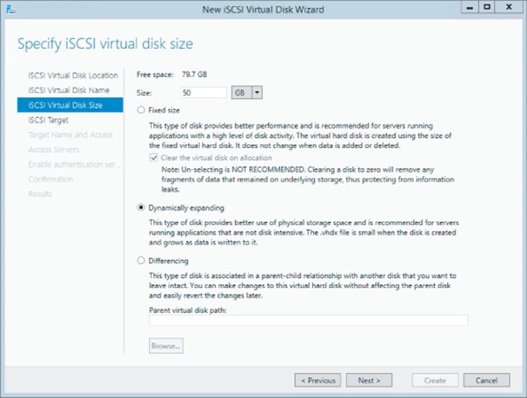
Figure 4.9 Selecting the options for the new iSCSI VHDX target
Note the whole creation can also be automated in PowerShell using the New-IscsiVirtualDisk and New-IscsiServerTarget cmdlets. At this stage, you have a Windows-hosted iSCSI target that has been configured so that specific IQNs can access it. If the Windows iSCSI target is used to host important data, then a cluster should be used to provide the iSCSI service, which is fully cluster supported.
Using the Windows iSCSI Initiator
While the iSCSI target is built into Windows Server, by default the service, called Microsoft iSCSI Initiator, is not started, and its startup is set to manual. The first time you launch the iSCSI Initiator Control Panel applet you will be notified that the service is not running and asked if you wish the service to be modified so it starts automatically. Click Yes.
The iSCSI Initiator properties are accessed through a number of property tabs. The Configuration tab shows the IQN of the client (which can be modified) and also allows CHAP and IPsec configurations. Most of the actions you need to perform are through the Discovery and Targets tabs.
On the Discovery tab, click the Discovery Portal button, enter the DNS name or IP address of the iSCSI server, and click OK. This will perform a scan of all the targets on the specified server that the initiator has permission to access. To connect to one of the targets, select the Targets tab, select a discovered target, and click Connect. This will connect to the storage and add it as a favorite by default, which means it will automatically connect after reboots, as shown in Figure 4.10. Once connected in Disk Manager the new disk will be shown where it should be brought online, initialized and formatted.
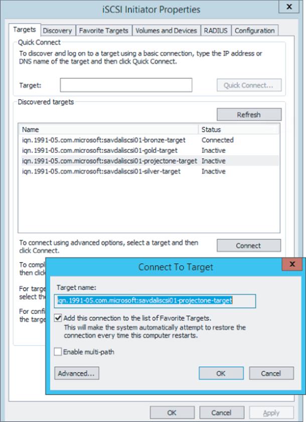
Figure 4.10 Connecting to a new iSCSI target using the built-in iSCSI Initiator
This connection could be made from a Hyper-V host to access storage or from within your virtual machine. The benefit of iSCSI is that multiple iSCSI Initiators can connect to the same iSCSI target, which would enable shared storage and numerous failover cluster scenarios within the virtual machines.
Considerations for Using iSCSI
Using iSCSI to enable shared storage between virtual machines in Windows Server 2008 R2 was the only option and was also the only way to access volumes greater than 2 TB (when not connecting to a Windows iSCSI target, which still had a 2 TB limit because it used VHD as the storage) without using a pass-through disk. If iSCSI is the storage standard for your organization, then using it within virtual machines is still a workable solution. With Windows Server 2012 R2, though, there is a better option, which I will go into in section “Leveraging Shared VHDX.” A benefit of iSCSI is that the Hyper-V host itself does not require any access to the storage. The virtual machine's guest OS IQN is what is given permission to the target and not the host.
There are also some challenges you should be aware of when using iSCSI:
· Hyper-V has no knowledge that the virtual machine is using iSCSI-connected storage.
· If a backup is taken of the virtual machine at the Hyper-V host, then none of the data stored in iSCSI targets would be backed up.
· While technologies like Live Migration and Hyper-V Replica (only if the VSS integration component is disabled for the VM) will still function, they protect and move only the VHDX/VHD content and not data stored on iSCSI targets.
· To use iSCSI, the guest operating system must know details of the iSCSI fabric, which may not be desirable, especially in hoster scenarios.
Understanding Virtual Fibre Channel
While iSCSI provided a method to enable shared storage within virtual machines, many organizations did not use iSCSI and instead relied on fibre channel to access their SAN environments. These organizations wanted to enable virtual machines to be able to access the SAN directly using the host's fibre channel host bus adapter (HBA, basically similar to a network card but used to connect to storage fabric with technologies to enable very fast and efficient movement of data).
Windows Server 2012 introduced Virtual Fibre Channel to allow virtual machines to directly connect to storage on a fibre channel–connected SAN whose architecture is like that shown in Figure 4.11. The architecture is similar in structure to how networking works with Hyper-V.
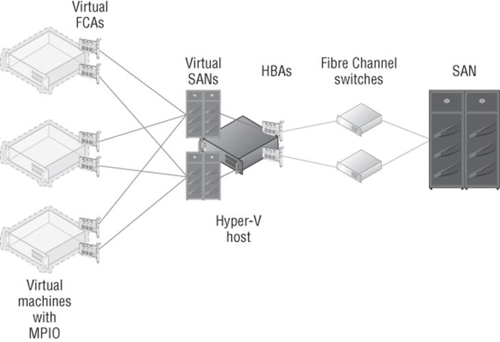
Figure 4.11 Using virtual fibre channel with Hyper-V
Notice in Figure 4.11 that on the Hyper-V host one or more virtual SANs are created, and they connect to one or more HBAs on the Hyper-V host. The key is to not introduce a single point of failure, which means there are multiple virtual SANs connected to different HBAs that connect to different physical switches, and then within the virtual machines, there are multiple virtual adapters, each connecting to a different virtual SAN.
To use virtual fibre channel, the HBA must support and be enabled for N-Port ID Virtualization (NPIV), which allows virtual port IDs to share a single physical port. If your HBA does not support NPIV or NPIV is not enabled, this will be shown when you are trying to create a virtual SAN, as shown in Figure 4.12.
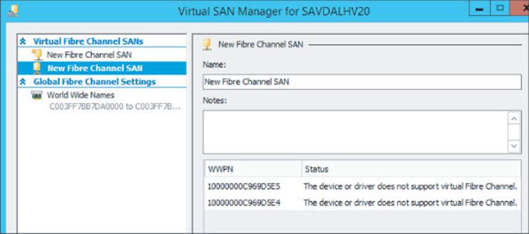
Figure 4.12 Problem with the ports that will block using in a virtual SAN
There are some key steps to take when trying to resolve supportability with NPIV:
1. Make sure the HBA supports NPIV. This seems obvious, but check the specifications of the HBA to ensure that it will work with NPIV.
2. Check if NPIV is enabled. Many HBAs ship with NPIV disabled by default. Use whatever management application is available to ensure that NPIV is enabled. As shown in Figure 4.13, I used the OneCommand Manager tool to see if NPIV is enabled on my Emulex card.
3. Update the firmware for the HBA and the driver on the Hyper-V host. Note that if you update the firmware, it may reset NPIV to disabled again, so you will need to reenable it. In my experience, a firmware and driver update is often required to fully enable NPIV.
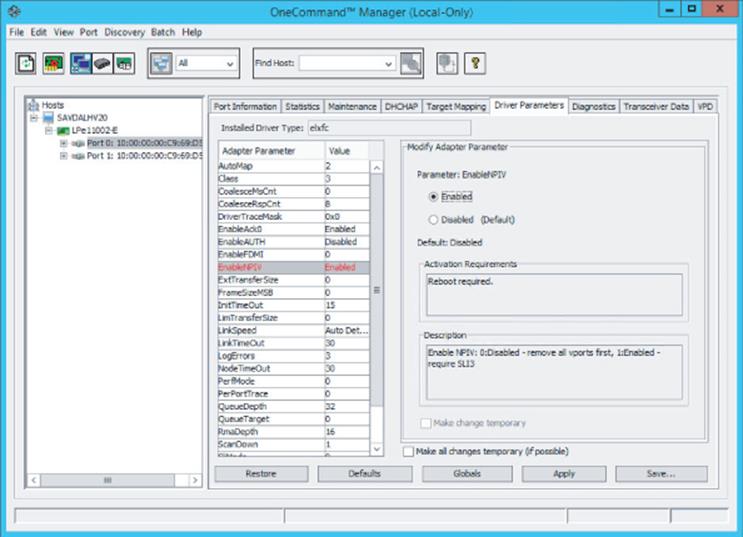
Figure 4.13 Enabling NPIV using the OneCommand Manager tool
Assuming I have two HBA ports in my Hyper-V host, I will create two separate virtual SANs, each connected to one of the HBA ports. This assumes that each of the HBA ports is connected to a different fibre channel switch to remove single points of failure. If you have four HBA ports, each virtual SAN would be configured with two of the HBA ports. A single HBA port cannot be assigned to more than one virtual SAN. My configuration is shown in Figure 4.14 with two virtual SANs, each using one of the available ports.
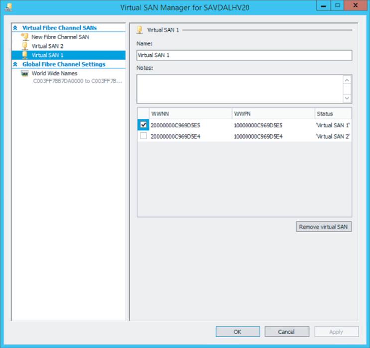
Figure 4.14 A virtual SAN using one of the available HBA ports
Once the virtual SANs are created, the next step is to add virtual fibre channel adapters (vFCAs) to the virtual machines that need to access the storage. Open the settings of the virtual machine, and in the Add Hardware section, select Fibre Channel Adapter and click Add. Each virtual machine should have two vFCAs, each connected to a different virtual SAN, providing the virtual machine with redundant connections and protection from a single point of failure as highlighted in Figure 4.11 previously. The only configuration for the vFCA is to select the virtual SAN it will connect to, and each vFCA is assigned two sets of World Wide Port Names (WWPNs), as shown in Figure 4.15, which are used to zone access to storage in the switches, effectively granting access to storage. I will cover why each vFCA gets two WWPNs later. Notice the Copy button that will take the WWPN and World Wide Node Name (WWNN) information for the vFCA and copy it to the Clipboard; it can then be used in your notes or in your switch configuration tool to zone storage.
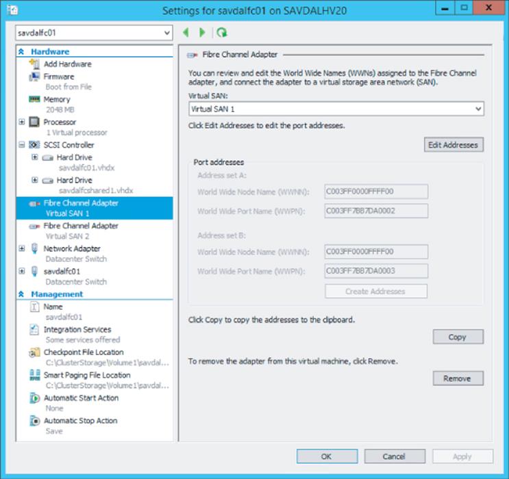
Figure 4.15 A virtual fibre channel adapter for a virtual machine
With the WWPNs available, the next step would be in your switch to zone storage to the WWPNs (both of the WWPNs for each adapter) of the virtual machine and assign to LUNs on the SAN. When you start a virtual machine with vFCAs assigned but currently with no storage zoned to those vFCAs, you will notice that the virtual machine progress stays at 1% when starting for 90 seconds. This is because the vFCA picks a HBA from the virtual SAN it is connected to and calls the HBA driver to create a virtual port. The vFCA then looks for at least one LUN to be accessible before it continues. If there is no storage zoned to the vFCA, then this LUN check will not work and the 90-second time-out has to expire and an event log will be written:
Log Name: Microsoft-Windows-Hyper-V-SynthFC-Admin
Source: Microsoft-Windows-Hyper-V-SynthFcVdev
Date: 10/9/2013 2:13:08 PM
Event ID: 32213
Task Category: None
Level: Warning
Keywords:
User: NT VIRTUAL MACHINE\1F2AA062-7677-45C0-86F6-643C33796A9D
Computer: savdalhv20.savilltech.net
Description:
'savdalfc01': No LUNs have appeared for Synthetic Fibre Channel HBA
Fibre Channel Adapter (BB50C162-40E7-412B-AB06-B34104CF6D17). The
VM has been started after the timeout period (90 seconds). Please
review the LUN mappings for the virtual port. (Virtual machine ID
1F2AA062-7677-45C0-86F6-643C33796A9D)
You may need to start this way initially so the WWPNs show on the fibre channel switch to allow them to be zoned. Then once available storage is zoned, the result will be another event log being written to show that storage is now available on the vFCA:
Log Name: Microsoft-Windows-Hyper-V-SynthFC-Admin
Source: Microsoft-Windows-Hyper-V-SynthFcVdev
Date: 10/9/2013 3:33:42 PM
Event ID: 32210
Task Category: None
Level: Information
Keywords:
User: NT VIRTUAL MACHINE\1F2AA062-7677-45C0-86F6-643C33796A9D
Computer: savdalhv20.savilltech.net
Description:
'savdalfc01': A new LUN '\\?\SCSI#VMLUN&Ven_NETAPP&Prod_LUN#5&12d7e3f3&0&070000#{6f416619-
9f29-42a5-b20b-37e219ca02b0}' has been added for the Synthetic Fibre
Channel HBA Fibre Channel Adapter (BB50C162-40E7-412B-AB06-B34104CF6D17).
(Virtual machine ID 1F2AA062-7677-45C0-86F6-643C33796A9D)
I want to step back now and cover why each vFCA has two WWPNs. One of the most used features of Hyper-V is Live Migration, which is the ability to move a virtual machine between hosts with no downtime to the virtual machine. It was important that virtual fibre channel did not break the ability to live migrate a virtual machine. However, if a vFCA had a single WWPN when a virtual machine was moved to another host as part of the migration, it would be necessary to temporarily disconnect the connection to the storage so the WWPN could be used on the target host, which would result in storage access interruption. Therefore, each vFCA has two WWPNs, which enables the second WWPN to be used on the target of the live migration, enabling both the source and targets to be connected to the storage during a live migration and avoiding any interruption. As live migrations are performed, the WWPN used will switch between the A and B set with each migration. This is important because when you are zoning the storage, you must zone both the A and B WWPN or if you live migrate the virtual machine, it will lose access. It may be necessary to perform a live migration of the virtual machines to activate the second set of WWPNs to allow them to be zoned on the switches if you cannot manually specify WWPNs that are not currently visible to the switch. This means the process may look like this:
1. Start the virtual machine.
2. Connect to the switch, and create an alias (or any other construct, depending on the switch) for the visible WWPNs.
3. Live migrate the virtual machine to another host, which will trigger the other set of WWPNs to activate.
4. On the switch, add the newly visible WWPNs to the alias.
5. Complete zoning to storage.
Figure 4.16 shows my switch with an alias created for each of the vFCAs for each virtual machine. Notice that each alias has two WWPNs, the A and the B set, but only one is active. Figure 4.17 shows the same view after I live migrate the two virtual machines to another host. Notice now the second set of WWPNs are active.
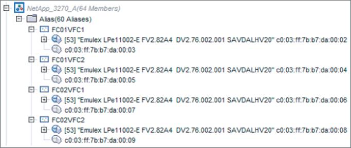
Figure 4.16 The A set of WWPNs being used
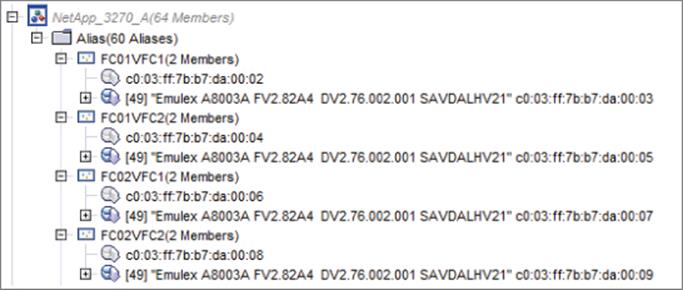
Figure 4.17 The B set of WWPNs being used
What is a great feature here is that the Hyper-V host itself has no access to the storage. Nowhere is the WWPN of the host zoned to storage; only the virtual machines have access to the storage, which is important from a security perspective and simplifies management because there is no need to ensure that every Hyper-V host is zoned to storage, only the virtual machines' vFCAs that actually need the access.
With storage now zoned to all the WWPNs for the vFCAs used, the virtual machines can be started and the storage can be accessed as shared storage, allowing guest clustering. While this is not a Hyper-V–specific step, it is important to realize in my architecture shown in Figure 4.11 that I have redundant paths to the storage through my two vFCAs and the two virtual SANs (which can both see the storage via redundant path), which means for each LUN zoned the storage will actually be seen four times, as shown in Figure 4.18. Basically, each virtual SAN sees each disk twice, once for each of its paths to the storage, and then the virtual machine has two connections to different virtual SANs, each telling it there are two disks! This would be the same experience if redundant path iSCSI was used.
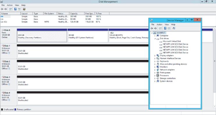
Figure 4.18 A view of a single disk without MPIO
Windows has a feature called MPIO that solves this and adds the intelligence into Windows so it understands that it's actually seeing the same storage multiple times and it has redundant paths. Install the MPIO feature and then run the MPIO tool. On the Discover Multi-Paths tab, select the SAN device and click Add, and then you will be prompted to reboot. Once the machine reboots, there will be a single instance of each disk, as shown in Figure 4.19.
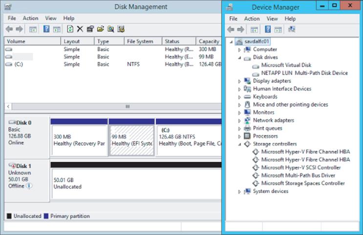
Figure 4.19 A view of a single disk with MPIO
The addition of virtual Fibre Channel is a great feature for organizations that have a fibre channel–centric storage strategy, and Microsoft made great efforts to provide a flexible while secure implementation, enabling full Live Migration compatibility without giving the Hyper-V hosts themselves access. There are still considerations. As with iSCSI, a backup taken at the Hyper-V host will not back up any data stored on the SAN storage. To use Virtual Fibre Channel, you must have a guest operating system that is Windows Server 2008 or above and the latest version of Hyper-V Integration Services must be installed. At time of this writing, Virtual Fibre Channel does not work with Linux guest operating systems. Hyper-V Replica cannot be used with a virtual machine that has vFCAs. Also, as with iSCSI, to use Virtual Fibre Channel, the virtual machines need to have knowledge of the storage fabric, which is not desirable in many scenarios, especially those hoster scenarios.
Leveraging Shared VHDX
Windows Server 2012 R2 provides a feature that for most environments will remove the need to use iSCSI inside the virtual machine or Virtual Fibre Channel and remove the need to expose the storage fabric details to the virtual machine. Shared VHDX allows a VHDX file to be connected to multiple virtual machines simultaneously, and the shared VHDX will be seen as shared storage (shared SAS) and therefore used as cluster storage within guest clusters. The requirements for shared VHDX are as follows:
1. Must use Windows Server 2012 R2 Hyper-V.
2. Guest operating systems must be Windows Server 2012 or above and must be running the Windows Server 2012 R2 Integration Services.
3. The disk must be VHDX, not VHD, and must be connected to a SCSI controller, not IDE. It can be a generation 1 or generation 2 virtual machine.
4. VHDX can be fixed or dynamic but not differencing.
5. Can be used for data disks only. Cannot be used for operating system disks.
6. The storage for the VHDX file being shared must either be a Cluster Shared Volume (CSV) or be hosted from a scale-out file server (SoFS) accessed using SMB 3 (the SoFS would be using CSV for its backend storage). The reason CSV must be used to store the VHDX is that the code to implement the VHDX sharing is part of CSV and not the regular NTFS code.
It is actually possible to force the process of loading and attaching the shared VHD filter driver to a non-CSV volume. However, this loading will survive only until the disk is offlined in some way, at which point you would have to load and attach again. Note that this is not supported or even tested by Microsoft and should be used only in basic test scenarios if a CSV is not available.
1. Install the Failover Clustering feature through Server Manager or through PowerShell:
Install-WindowsFeature Failover-Clustering
2. Run the following command, specifying the volume to attach the shared VHDX filter to:
FLTMC.EXE attach svhdxflt <volume>:
Providing a VHDX file is stored on a CSV volume or SoFS and it is connected via a SCSI controller, there is only one step to make it shared: Once it has been added to a virtual machine in the Advanced Features properties for the disk, check the Enable Virtual Hard Disk Sharing option, as shown in Figure 4.20. Repeat this for the same disk on all virtual machines that need to access the shared disk.
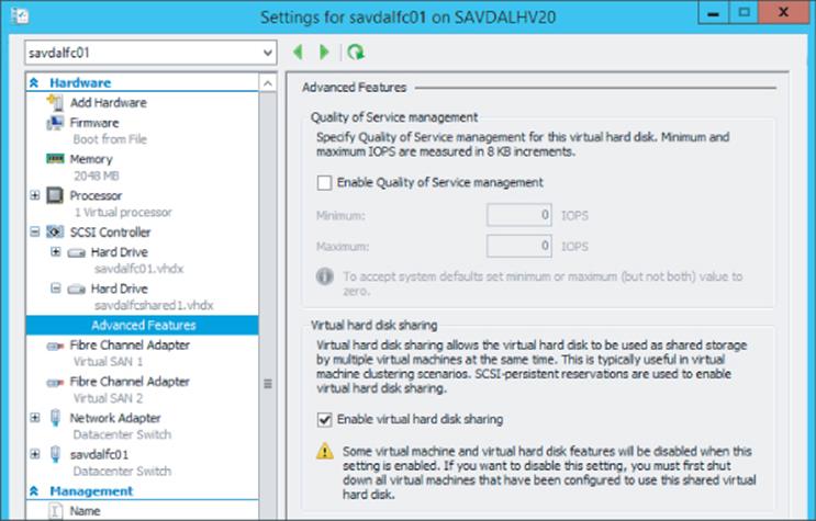
Figure 4.20 Setting a VHDX file as shared
This process could also be accomplished using PowerShell. In the following example, I have two virtual machines, savdalfc01 and savdalfc02, to which I will add a shared VHDX file. Notice the use of the -ShareVirtualDisk switch when I add the VHDX file to the virtual machine.
New-VHD -Path C:\ClusterStorage\Volume1\SharedVHDX\Savdalfcshared1.vhdx '
-Fixed -SizeBytes 25GB
Add-VMHardDiskDrive -VMName savdalfc01 -Path '
C:\ClusterStorage\Volume1\SharedVHDX\Savdalfcshared1.vhdx -ShareVirtualDisk
Add-VMHardDiskDrive -VMName savdalfc02 -Path '
C:\ClusterStorage\Volume1\SharedVHDX\Savdalfcshared1.vhdx -ShareVirtualDisk
To check if a virtual disk is using a shared VHDX, the SupportPersistentReservations property can be examined. If it is set to True, then it is a shared VHDX. For example, notice that my shared VHDX file has a value of True:
PS C:\> Get-VMHardDiskDrive -VMName savdalfc01 | ft vmname, path, ´
controllertype, SupportPersistentReservations -auto
VMName Path ControllerType SupportPersistentReservations
------ ---- -------------- ---------
savdalfc01 C:\ClusterSto..\savdalfc01\savdalfc01.vhdx SCSI False
savdalfc01 C:\ClusterSto.. \Shared VHDX\savdalfcshared1.vhdx SCSI True
Within the virtual machine, the shared VHDX would be seen as a regular shared SAS disk and used like normal shared storage. The huge benefit with shared VHDX is that the virtual machine knows nothing about the underlying storage fabric and provides complete abstraction for the storage from the physical storage fabric.
Because the VHDX file is shared between multiple virtual machines, the ability to perform a backup at the Hyper-V host or even a checkpoint is not possible. Backups would need to be taken within the guest virtual machine. Storage migration is also not supported for shared VHDX files. This also means Hyper-V Replica cannot be used for virtual machines that are connected to a shared VHDX file.
When using Shared VHDX on an SMB 3.0 share an entirely new protocol called Remote Shared Virtual Hard Disk Protocol is used. This protocol leverages SMB as a transport but is not actually part of the SMB protocol itself.
Hopefully, you can see that there is a large range of options for shared storage within virtual machines, including SMB 3, iSCSI, Virtual Fibre Channel, and shared VHDX. Each has its own benefits and considerations, and I don't think there is a right or wrong solution as long as you take time to fully understand each technology. I think where possible you should use shared VHDX first because it provides a true virtualized shared storage solution that removes the need for direct fabric knowledge and configuration from the virtual machines.
Data Deduplication and Hyper-V
So far I hope I have covered some of the reasons Windows Server 2012 R2 is a great storage platform. Storage Spaces with its thin provisioning and auto-recovery, improved ChkDsk error correction, iSCSI and SMB 3.0 servers, and VHDX are amazing features. There are many other features, such as the new ReFS file system and industry-leading NFS implementation, but I want to touch on one more feature that in Windows Server 2012 I would not have covered but is now applicable to virtualization, and that is data deduplication.
Windows Server 2012 introduced the block-level data deduplication capability as an optional role available within the File and iSCSI Services collection of role services. In Windows Server 2012, data deduplication did not work on any file that had an exclusive lock open, which was the case for a virtual hard disk used by a virtual machine. This meant that the data deduplication feature was useful only for reducing space for archived virtual machine or libraries of content.
In Windows Server 2012 R2 the data deduplication functionality has been improved to work on exclusively locked files and can therefore deduplicate virtual hard disks used by Hyper-V virtual machines. For the Windows Server 2012 R2 release, though, deduplication is supported for only a single scenario, and that is for the deduplication of VDI deployment virtual machines, primarily personal desktop deployment that often results in a very large amount of duplicated content. When you leverage the data deduplication capability at the file system level, all the duplicated blocks within a virtual hard disk and between different virtual hard disks would be single-instanced, resulting in huge disk savings. Windows Server 2012 R2 also adds support for deduplication for Cluster Shared Volumes, which means deduplication can be used on shared cluster disks and on the storage of scale-out file servers.
The way the data deduplication works is that a periodic scan of the file system is performed and the blocks on disk have a hash value created. If blocks are found with the same value, it means the content is the same and the block is moved to a single instance store and the old locations now point to the single-instance store copy. The block size used is variable to achieve the greatest level of deduplication. It is not uncommon to see disk space savings of up to 95 percent in VDI environments because most of the content of each virtual hard disk is the same as the other virtual hard disk instances. Using deduplication actually speeds up the performance of VDI environments due to improvements in caching instead of having a negative performance impact, which may be expected.
It should be noted that while in Windows Server 2012 R2 the data deduplication is supported for VDI deployments, the actual data deduplication is a core part of the storage stack and so there is no block to stop data deduplication working with other virtual workloads. However, these workloads have not been tested. There are some types of workloads I would be very concerned about enabling data deduplication on, such as any kind of database. It is therefore important that when configuring data deduplication on a volume that has mixed workloads, you explicitly block folders containing virtual hard disks you do not want to be deduplicated.
VDI is actually one of the great scenarios for using differencing disks, which remember are child disks of a parent disk with only differences stored in them. If data that is being read is not in the differencing disk, it is read from the parent disk. Any write actions are performed into the differencing disk. Therefore, in a pooled VDI scenario, a master VHDX file would have the core Windows client image, the gold image, and then many VDM virtual machines created with their own differencing disks that are children of the master image. Each differencing disk would still be a couple of gigabytes due to changes made during the specialization phase, but using differencing disks is still a very efficient solution. The master image can be stored on a high tier of storage, such as the SSD tier if Storage Spaces is being used, and because the master would be read-only, it would also benefit from any caching. Figure 4.21 shows this architecture.
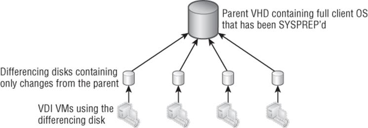
Figure 4.21 Using differencing disks in a VDI environment
Storage Quality of Service
Many organizations have long focused on ensuring that virtual machines correctly get the required amounts of memory and processor resources while network and storage controls historically have not been well implemented. Windows Server 2012 R2 introduces basic IOPS-based QoS on a per-virtual-hard-disk level. There are two settings:
· Minimum IOPS: If the virtual hard disk does not receive the configured minimum number of IOPS, an event log is generated.
· Maximum IOPS: The virtual hard disk will be hard limited to the number of IOPS specified.
You will notice that the minimum and maximum options are implemented very differently. There is no “guaranteed” minimum number of IOPS possible for a virtual machine because there is no way to ensure that the required number of IOPS is possible or even available. Therefore, the best solution at this time is for an event to be generated notifying that the virtual hard disk is not receiving the number of IOPS required which will be an Event ID 32930 under Applications and Services Logs\Microsoft\Windows\Hyper-V-VMMS\Admin and an Event ID 32931 when performance is back to the expected level. A WMI event is also triggered. It is simple to make sure a virtual hard disk does not exceed a certain number of IOPS, which is why the maximum value is a hard limit and simply limits the virtual hard disk to the configured number of IOPS. To configure the storage QoS, perform the following steps:
1. Open the settings of a virtual machine.
2. Navigate to the virtual hard disk and select Advanced Features.
3. Check the Enable Quality Of Service Management check box and set the Minimum and/or Maximum values as shown in Figure 4.22. A value of 0 means there is no configuration. Click OK.
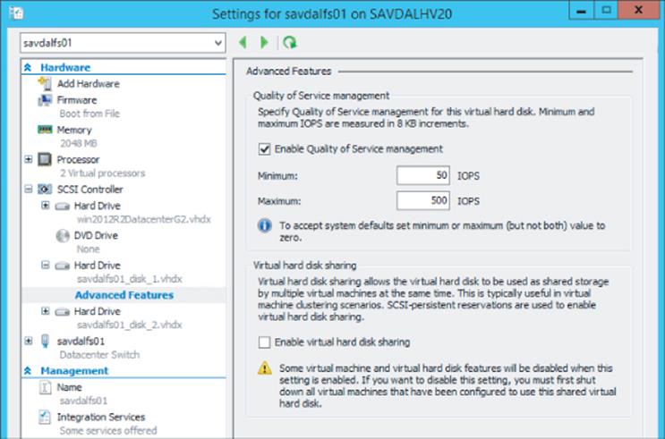
Figure 4.22 Configuring QoS for a disk
To configure storage QoS using PowerShell, use the Set-VMHardDiskDrive cmdlet and configure the MaximumIOPS and MinimumIOPS parameters.
In addition to enabling QoS on storage, storage details are also now reported as part of the resource metering introduced in Windows Server 2012. The storage-related data returned includes the average IOPS, average latency, and the data read and written in MB. An example of the information returned is shown in the following output:
PS E:\> Measure-VM -VMName savdalfs01 | fl
ComputerName : SAVDALHV01
VMId : 4c6db747-8591-4287-a8fc-ac55e37dba16
VMName : savdalfs01
HardDiskMetrics : {Microsoft.HyperV.PowerShell
.VirtualHardDiskMetrics, Microsoft.HyperV.PowerShell.VirtualHardDiskMetrics}
MeteringDuration :
AverageProcessorUsage : 204
AverageMemoryUsage : 3236
MaximumMemoryUsage : 3236
MinimumMemoryUsage : 3236
TotalDiskAllocation : 260096
AggregatedAverageNormalizedIOPS : 389
AggregatedAverageLatency : 633
AggregatedDiskDataRead : 103
AggregatedDiskDataWritten : 367
NetworkMeteredTrafficReport : {Microsoft.HyperV.PowerShell.VMNetworkAdapterPortAclMeteringReport,
Microsoft.HyperV.PowerShell.VMNetworkAdapterPortAclMeteringReport,
Microsoft.HyperV.PowerShell.VMNetworkAdapterPortAclMeteringReport,
Microsoft.HyperV.PowerShell.VMNetworkAdapterPortAclMeteringReport}
AvgCPU : 204
AvgRAM : 3236
MinRAM : 3236
MaxRAM : 3236
TotalDisk : 260096
Another type of storage Quality of Service (QoS) is applicable with the adoption of SMB 3.0 for not just file traffic (default) but also for hosting virtual machines and even for Live Migration. The existing QoS technologies that could control SMB allocation is not granular enough to enable different bandwidth limits for the different types of SMB traffic. Windows Server 2012 R2 adds this new granularity for SMB bandwidth management: Default, LiveMigration, and VirtualMachine. This allows an amount of bandwidth to be specified for each of the types of SMB traffic. In most environments, this should not be required because SMB does a good job of fair-sharing the network, but if you need to better tune the bandwidth allocation, the new SMB bandwidth management will be useful.
To configure the SMB bandwidth management, perform the following steps:
1. Install the SMB Bandwidth Limit feature. This can be done through Server Manager (note that it is a feature and not a role) or using PowerShell.
Install-WindowsFeature FS_SMBBW
2. Configure the limits for each type of traffic using the Set-SMBBandwidthLimit PowerShell cmdlet, as in this example:
Set-SMBBandwidthLimit -Category LiveMigration - BytesPerSecond 2GB
3. To view the configured SMB QoS, use the Get-SMBBandwidthLimit cmdlet. Use the Remove-SMBBandwidthLimit cmdlet to remove it.
SAN Storage and SCVMM
This chapter has shown a lot of great functionality that is enabled through the use of the Windows Server platform, but this does not mean that there are not investments related to leveraging SANs. One of the biggest features when utilizing SANs is offloaded data transfer, or ODX.
Typically, when any file move or copy operating occurs, the server becomes the bottleneck in the process and significant resources are used on the server as the following occurs:
1. The server reads a portion of the data from the SAN.
2. The server writes the portion of the data to the SAN.
3. Both steps are repeated until all data is read and written.
This is a highly inefficient process because the SAN is far more capable of natively moving or copying data. ODX allows the SAN to move or copy data itself through the use of a series of tokens, with each token representing a portion of the data at a point in time. The token, instead of the actual data, is passed by the host to the SAN, which then allows the SAN to natively move or copy the data.
To utilize ODX, the SAN must support it, and the good news is that by default, ODX will be utilized where possible automatically. Consider the action of deploying a virtual machine from a template. In the past, the Hyper-V host would copy the template to the new location, resulting in large amounts of processor utilization on the host and a copy operation that may take 10 minutes to perform. With ODX, the copy would use a negligible amount of processor resource and the copy operation would likely finish in about 30 seconds. File operations using Windows Explorer, the command prompt, PowerShell, and Hyper-V will all utilize ODX where possible.
System Center Virtual Machine Manager (SCVMM) 2012 R2 also now utilizes ODX when deploying a virtual machine from a template but not in any other scenario. If ODX cannot be used, SCVMM will use a regular file copy, and if that does not work, it will resort to BITS.
While native ODX allows very fast copies of data because the SAN can natively perform the copy/move directly, it also allows SAN vendors to improve the process. For example, there is no reason the SAN has to actually copy the data. SAN ODX implementations may use native capabilities such as just creating a pointer to the original data. The NetApp implementation uses its sub-LUN cloning technology, which creates two pointers to the same block of data, so the operation finishes almost instantly because no data is actually being moved or copied. A write-forward snapshot is then leveraged so changes to the new copy are written to a new area. Even without these additional optimizations, ODX provides a huge performance improvement during large move and copy operations.
Windows Server 2012 also introduced native support for Storage Management Initiative Specification (SMI-S), and in Windows Server 2012 R2, there is a built-in SMI-S provider for the inbox iSCSI solution, making it manageable from SMI-S–based management solutions without additional software required, which includes SCVMM 2012 R2.
I want to close by mentioning how SCVMM 2012 R2 can integrate with storage solutions to simplify management. The goal of SCVMM is to be the fabric management solution and not just for managing virtual machines. Storage providers can be loaded into SCVMM, which then displays the aggregates/volumes and the contained LUNs. Each aggregate/volume can be assigned a custom classification such as Gold, Silver, or Bronze. Figure 4.23 shows the Classifications And Pools view of the storage fabric. As you can see, I have three classifications of storage defined, and I have a number of different storage subsystems loaded, including a Windows Server 2012 R2 iSCSI server and two NetApp SANs. Using a common classification enables SCVMM to automatically create and allocate LUNs to hosts as required based on a storage classification in the virtual machine request.
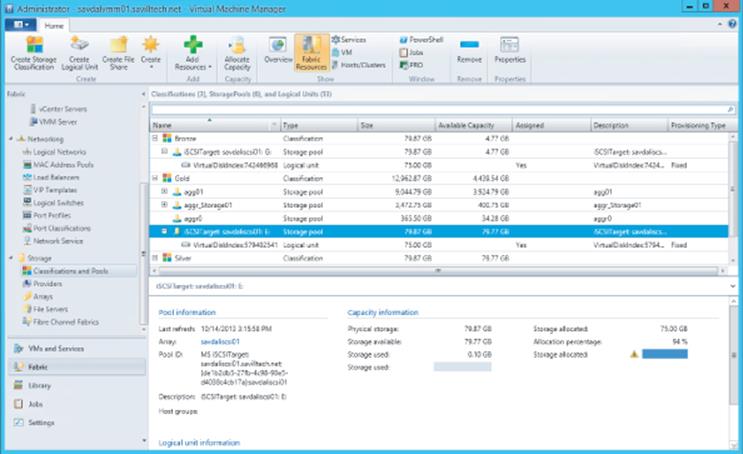
Figure 4.23 A view of storage managed by SCVMM 2012 R2
SCVMM leverages industry standards to connect to the storage subsystems such as CIM- and WMI-based versions of SMI-S and also Windows storage APIs to manage Windows file servers, which can also be classified in SCVMM 2012 R2. I will cover SCVMM in more detail later in the book, but all of the storage features related to VHDX, SMB, and virtual fibre channel can be managed through SCVMM 2012 R2. In addition, SCVMM 2012 R2 can deploy complete file server clusters in addition to Hyper-V hosts.
The Bottom Line
1. Explain the types of storage available to a virtual machine. Windows Server 2012 R2 provides a number of different types of storage to a virtual machine. VHDX files provide a completely abstracted and self-contained virtual container for file systems available to virtual machines, and 2012 R2 allows a VHDX file connected to the SCSI bus to be shared between multiple virtual machines, providing shared storage. Additionally, storage can be exposed to virtual machines that are hosted in SAN environments through the use of iSCSI running inside the guest operating system or through the new virtual fibre channel capability.
1. Master It Why is MPIO required?
2. Identify when to use Virtual Fiber Channel and when to use shared VHDX and the benefits of each. Virtual Fibre Channel allows virtual machines to be directly connected to a fibre channel SAN without the host requiring zoning to the storage, but it requires knowledge of the storage fabric. Shared VHDX provides shared storage to the virtual machine without requiring that the users of the shared VHDX have knowledge of the storage fabric, which is useful in hosting the type of scenarios where all aspects of the physical fabric should be hidden from the users.
3. Articulate how SMB 3.0 can be used. SMB 3.0 went through a huge upgrade in Windows Server 2012, providing an enterprise-level file-based protocol that can now be used to store Hyper-V virtual machines. This includes additional storage options for Hyper-V environments, including fronting existing SANs with a Windows Server 2012 R2 scale-out file server cluster to extend the SAN's accessibility beyond hosts with direct SAN connectivity.
1. Master It Which two SMB technologies enable virtual machines to move between nodes in a SoFS without any interruption to processing?
All materials on the site are licensed Creative Commons Attribution-Sharealike 3.0 Unported CC BY-SA 3.0 & GNU Free Documentation License (GFDL)
If you are the copyright holder of any material contained on our site and intend to remove it, please contact our site administrator for approval.
© 2016-2026 All site design rights belong to S.Y.A.