Windows Internals, Sixth Edition, Part 2 (2012)
Chapter 11. Cache Manager
The cache manager is a set of kernel-mode functions and system threads that cooperate with the memory manager to provide data caching for all Windows file system drivers (both local and network). In this chapter, we’ll explain how the cache manager, including its key internal data structures and functions, works; how it is sized at system initialization time; how it interacts with other elements of the operating system; and how you can observe its activity through performance counters. We’ll also describe the five flags on the Windows CreateFile function that affect file caching.
NOTE
None of the cache manager’s internal functions are outlined in this chapter beyond the depth required to explain how the cache manager works. The programming interfaces to the cache manager are documented in the Windows Driver Kit (WDK). For more information about the WDK, see http://www.microsoft.com/whdc/devtools/wdk/default.mspx.
Key Features of the Cache Manager
The cache manager has several key features:
§ Supports all file system types (both local and network), thus removing the need for each file system to implement its own cache management code
§ Uses the memory manager to control which parts of which files are in physical memory (trading off demands for physical memory between user processes and the operating system)
§ Caches data on a virtual block basis (offsets within a file)—in contrast to many caching systems, which cache on a logical block basis (offsets within a disk volume)—allowing for intelligent read-ahead and high-speed access to the cache without involving file system drivers (This method of caching, called fast I/O, is described later in this chapter.)
§ Supports “hints” passed by applications at file open time (such as random versus sequential access, temporary file creation, and so on)
§ Supports recoverable file systems (for example, those that use transaction logging) to recover data after a system failure
Although we’ll talk more throughout this chapter about how these features are used in the cache manager, in this section we’ll introduce you to the concepts behind these features.
Single, Centralized System Cache
Some operating systems rely on each individual file system to cache data, a practice that results either in duplicated caching and memory management code in the operating system or in limitations on the kinds of data that can be cached. In contrast, Windows offers a centralized caching facility that caches all externally stored data, whether on local hard disks, floppy disks, network file servers, or CD-ROMs. Any data can be cached, whether it’s user data streams (the contents of a file and the ongoing read and write activity to that file) or file system metadata(such as directory and file headers). As you’ll discover in this chapter, the method Windows uses to access the cache depends on the type of data being cached.
The Memory Manager
One unusual aspect of the cache manager is that it never knows how much cached data is actually in physical memory. This statement might sound strange because the purpose of a cache is to keep a subset of frequently accessed data in physical memory as a way to improve I/O performance. The reason the cache manager doesn’t know how much data is in physical memory is that it accesses data by mapping views of files into system virtual address spaces, using standard section objects (file mapping objects in Windows API terminology). (Section objects are the basic primitive of the memory manager and are explained in detail in Chapter 10.) As addresses in these mapped views are accessed, the memory manager pages in blocks that aren’t in physical memory. And when memory demands dictate, the memory manager unmaps these pages out of the cache and, if the data has changed, pages the data back to the files.
By caching on the basis of a virtual address space using mapped files, the cache manager avoids generating read or write I/O request packets (IRPs) to access the data for files it’s caching. Instead, it simply copies data to or from the virtual addresses where the portion of the cached file is mapped and relies on the memory manager to fault in (or out) the data into (or out of) memory as needed. This process allows the memory manager to make global trade-offs on how much memory to give to the system cache versus how much to give to user processes. (The cache manager also initiates I/O, such as lazy writing, which is described later in this chapter; however, it calls the memory manager to write the pages.) Also, as you’ll learn in the next section, this design makes it possible for processes that open cached files to see the same data as do processes that are mapping the same files into their user address spaces.
Cache Coherency
One important function of a cache manager is to ensure that any process accessing cached data will get the most recent version of that data. A problem can arise when one process opens a file (and hence the file is cached) while another process maps the file into its address space directly (using the Windows MapViewOfFile function). This potential problem doesn’t occur under Windows because both the cache manager and the user applications that map files into their address spaces use the same memory management file mapping services. Because the memory manager guarantees that it has only one representation of each unique mapped file (regardless of the number of section objects or mapped views), it maps all views of a file (even if they overlap) to a single set of pages in physical memory, as shown in Figure 11-1. (For more information on how the memory manager works with mapped files, see Chapter 10.)
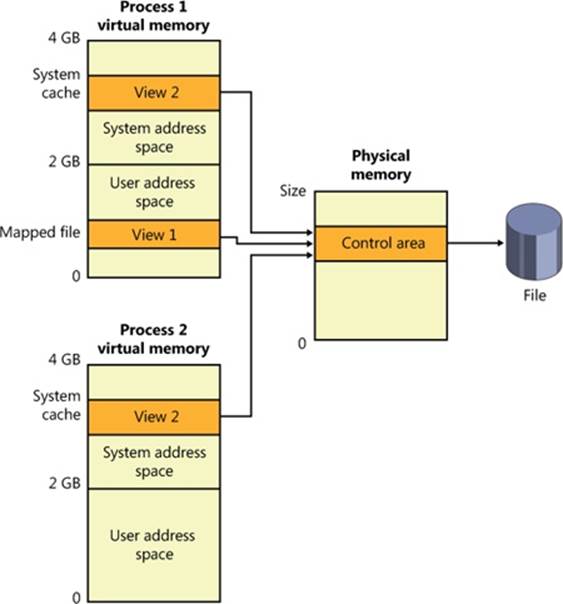
Figure 11-1. Coherent caching scheme
So, for example, if Process 1 has a view (View 1) of the file mapped into its user address space, and Process 2 is accessing the same view via the system cache, Process 2 will see any changes that Process 1 makes as they’re made, not as they’re flushed. The memory manager won’t flush all user-mapped pages—only those that it knows have been written to (because they have the modified bit set). Therefore, any process accessing a file under Windows always sees the most up-to-date version of that file, even if some processes have the file open through the I/O system and others have the file mapped into their address space using the Windows file mapping functions.
NOTE
Cache coherency in this case refers to coherency between user-mapped data and cached I/O and not between noncached and cached hardware access and I/Os, which are almost guaranteed to be incoherent. Also, cache coherency is somewhat more difficult for network redirectors than for local file systems because network redirectors must implement additional flushing and purge operations to ensure cache coherency when accessing network data. See Chapter 12, for a description of opportunistic locking, the Windows distributed cache coherency mechanism.
Virtual Block Caching
The Windows cache manager uses a method known as virtual block caching, in which the cache manager keeps track of which parts of which files are in the cache. The cache manager is able to monitor these file portions by mapping 256-KB views of files into system virtual address spaces, using special system cache routines located in the memory manager. This approach has the following key benefits:
§ It opens up the possibility of doing intelligent read-ahead; because the cache tracks which parts of which files are in the cache, it can predict where the caller might be going next.
§ It allows the I/O system to bypass going to the file system for requests for data that is already in the cache (fast I/O). Because the cache manager knows which parts of which files are in the cache, it can return the address of cached data to satisfy an I/O request without having to call the file system.
Details of how intelligent read-ahead and fast I/O work are provided later in this chapter.
Stream-Based Caching
The cache manager is also designed to do stream caching, as opposed to file caching. A stream is a sequence of bytes within a file. Some file systems, such as NTFS, allow a file to contain more than one stream; the cache manager accommodates such file systems by caching each stream independently. NTFS can exploit this feature by organizing its master file table (described in Chapter 12) into streams and by caching these streams as well. In fact, although the cache manager might be said to cache files, it actually caches streams (all files have at least one stream of data) identified by both a file name and, if more than one stream exists in the file, a stream name.
NOTE
Internally, the cache manager is not aware of file or stream names but uses pointers to these objects.
Recoverable File System Support
Recoverable file systems such as NTFS are designed to reconstruct the disk volume structure after a system failure. This capability means that I/O operations in progress at the time of a system failure must be either entirely completed or entirely backed out from the disk when the system is restarted. Half-completed I/O operations can corrupt a disk volume and even render an entire volume inaccessible. To avoid this problem, a recoverable file system maintains a log file in which it records every update it intends to make to the file system structure (the file system’s metadata) before it writes the change to the volume. If the system fails, interrupting volume modifications in progress, the recoverable file system uses information stored in the log to reissue the volume updates.
NOTE
The term metadata applies only to changes in the file system structure: file and directory creation, renaming, and deletion.
To guarantee a successful volume recovery, every log file record documenting a volume update must be completely written to disk before the update itself is applied to the volume. Because disk writes are cached, the cache manager and the file system must coordinate metadata updates by ensuring that the log file is flushed ahead of metadata updates. Overall, the following actions occur in sequence:
1. The file system writes a log file record documenting the metadata update it intends to make.
2. The file system calls the cache manager to flush the log file record to disk.
3. The file system writes the volume update to the cache—that is, it modifies its cached metadata.
4. The cache manager flushes the altered metadata to disk, updating the volume structure. (Actually, log file records are batched before being flushed to disk, as are volume modifications.)
When a file system writes data to the cache, it can supply a logical sequence number (LSN) that identifies the record in its log file, which corresponds to the cache update. The cache manager keeps track of these numbers, recording the lowest and highest LSNs (representing the oldest and newest log file records) associated with each page in the cache. In addition, data streams that are protected by transaction log records are marked as “no write” by NTFS so that the mapped page writer won’t inadvertently write out these pages before the corresponding log records are written. (When the mapped page writer sees a page marked this way, it moves the page to a special list that the cache manager then flushes at the appropriate time, such as when lazy writer activity takes place.)
When it prepares to flush a group of dirty pages to disk, the cache manager determines the highest LSN associated with the pages to be flushed and reports that number to the file system. The file system can then call the cache manager back, directing it to flush log file data up to the point represented by the reported LSN. After the cache manager flushes the log file up to that LSN, it flushes the corresponding volume structure updates to disk, thus ensuring that it records what it’s going to do before actually doing it. These interactions between the file system and the cache manager guarantee the recoverability of the disk volume after a system failure.
Cache Virtual Memory Management
Because the Windows system cache manager caches data on a virtual basis, it uses up regions of system virtual address space (instead of physical memory) and manages them in structures called virtual address control blocks, or VACBs. VACBs define these regions of address space into 256-KB slots called views. When the cache manager initializes during the bootup process, it allocates an initial array of VACBs to describe cached memory. As caching requirements grow and more memory is required, the cache manager allocates more VACB arrays, as needed. It can also shrink virtual address space as other demands put pressure on the system.
At a file’s first I/O (read or write) operation, the cache manager maps a 256-KB view of the 256-KB-aligned region of the file that contains the requested data into a free slot in the system cache address space. For example, if 10 bytes starting at an offset of 300,000 bytes were read into a file, the view that would be mapped would begin at offset 262144 (the second 256-KB-aligned region of the file) and extend for 256 KB.
The cache manager maps views of files into slots in the cache’s address space on a round-robin basis, mapping the first requested view into the first 256-KB slot, the second view into the second 256-KB slot, and so forth, as shown in Figure 11-2. In this example, File B was mapped first, File A second, and File C third, so File B’s mapped chunk occupies the first slot in the cache. Notice that only the first 256-KB portion of File B has been mapped, which is due to the fact that only part of the file has been accessed and because although File C is only 100 KB (and thus smaller than one of the views in the system cache), it requires its own 256-KB slot in the cache.
The cache manager guarantees that a view is mapped as long as it’s active (although views can remain mapped after they become inactive). A view is marked active, however, only during a read or write operation to or from the file. Unless a process opens a file by specifying theFILE_FLAG_RANDOM_ACCESS flag in the call to CreateFile, the cache manager unmaps inactive views of a file as it maps new views for the file if it detects that the file is being accessed sequentially. Pages for unmapped views are sent to the standby or modified lists (depending on whether they have been changed), and because the memory manager exports a special interface for the cache manager, the cache manager can direct the pages to be placed at the end or front of these lists. Pages that correspond to views of files opened with theFILE_FLAG_SEQUENTIAL_SCAN flag are moved to the front of the lists, whereas all others are moved to the end. This scheme encourages the reuse of pages belonging to sequentially read files and specifically prevents a large file copy operation from affecting more than a small part of physical memory. The flag also affects unmapping: the cache manager will aggressively unmap views when this flag is supplied.
If the cache manager needs to map a view of a file and there are no more free slots in the cache, it will unmap the least recently mapped inactive view and use that slot. If no views are available, an I/O error is returned, indicating that insufficient system resources are available to perform the operation. Given that views are marked active only during a read or write operation, however, this scenario is extremely unlikely because thousands of files would have to be accessed simultaneously for this situation to occur.
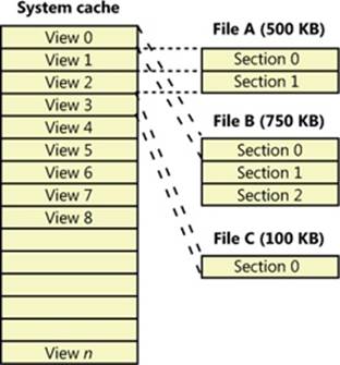
Figure 11-2. Files of varying sizes mapped into the system cache
Cache Size
In the following sections, we’ll explain how Windows computes the size of the system cache, both virtually and physically. As with most calculations related to memory management, the size of the system cache depends on a number of factors.
Cache Virtual Size
On a 32-bit Windows system, the virtual size of the system cache is limited solely by the amount of kernel-mode virtual address space and the SystemCacheLimit registry key that can be optionally configured. (See Chapter 10 for more information on limiting the size of the kernel virtual address space.) This means that the cache size is capped by the 2-GB system address space, but it is typically significantly smaller because the system address space is shared with other resources, including system paged table entries (PTEs), nonpaged and paged pool, and page tables. The maximum virtual cache size is 1,024 GB (1 TB) on 64-bit Windows.
Cache Working Set Size
As mentioned earlier, one of the key differences in the design of the cache manager in Windows from that of other operating systems is the delegation of physical memory management to the global memory manager. Because of this, the existing code that handles working set expansion and trimming, as well as managing the modified and standby lists, is also used to control the size of the system cache, dynamically balancing demands for physical memory between processes and the operating system.
The system cache doesn’t have its own working set but rather shares a single system set that includes cache data, paged pool, pageable Ntoskrnl code, and pageable driver code. As explained in the section System Working Sets in Chapter 10, this single working set is called internally the system cache working set even though the system cache is just one of the components that contribute to it. For the purposes of this book, we’ll refer to this working set simply as the system working set. Also explained in Chapter 10 is the fact that if the LargeSystemCache registry value is 1, the memory manager favors the system working set over that of processes running on the system.
EXPERIMENT: LOOKING AT THE CACHE’S WORKING SET
The !filecache debugger command dumps information about the physical memory the cache is using, the current and peak working set sizes, the number of valid pages associated with views, and the names of files mapped into views, where applicable, as you can see in the following output. (File system drivers cache metadata, such as directory structures and volume bitmaps, by using unnamed file streams.)
lkd> !filecache
***** Dump file cache******
Reading and sorting 999 VACBs ...
ReadVirtual: 85b77038 not properly sign extended
ReadVirtual: 85ba7010 not properly sign extended
Processing 998 active VACBs ...
File Cache Information
Current size 30528 kb
Peak size 65752 kb
461 Control Areas
Skipping view @ 91980000 - no VACB, but PTE is a prototype!
Loading file cache database (100% of 523264 PTEs)
SkippedPageTableReads = 882
File cache has 7668 valid pages
Usage Summary (in Kb):
Control Valid Standby/Dirty Shared Locked FsContext Name
85fa5be0 0 4 0 0 add0dbf8 $Directory
85f971b8 0 8 0 0 ad9bc918 $Directory
87c489f0 4 4 0 0 93b390f8 $Directory
87c4a9c0 4 0 0 0 93b38c30 $Directory
87c451a8 0 4 0 0 93b35780 $Directory
86a83710 4512 45432 0 0 86a90168 $Mft
85f96770 0 8 0 0 ad9c00f8 No Name for File
85e90998 0 512 0 0 abb83510 No Name for File
88062008 4 0 0 0 9e6c40f8 $Directory
87c291e8 44 164 0 0 93b400f8 $Directory
87c27e10 0 16 0 0 93b4bd08 $Directory
87b4bc88 236 84 0 0 93b28d08 $Directory
86ce23a8 12 0 0 0 a2051528 $Directory
87c2bb20 4 0 0 0 93b3b850 $Directory
87d51480 0 4 0 0 824f9830 $Directory
87c8c900 0 4 0 0 825b06d0 utmpx
87c2aa30 44 216 0 0 93b3fc70 $Directory
86ecc168 12 4088 0 0 9c3c5c50 Microsoft-Windows-
GroupPolicy%4Operational.evtx
...
Cache Physical Size
While the system working set includes the amount of physical memory that is mapped into views in the cache’s virtual address space, it does not necessarily reflect the total amount of file data that is cached in physical memory. There can be a discrepancy between the two values because additional file data might be in the memory manager’s standby or modified page lists.
Recall from Chapter 10 that during the course of working set trimming or page replacement the memory manager can move dirty pages from a working set to either the standby list or modified page list, depending on whether the page contains data that needs to be written to the paging file or another file before the page can be reused. If the memory manager didn’t implement these lists, any time a process accessed data previously removed from its working set, the memory manager would have to hard-fault it in from disk. Instead, if the accessed data is present on either of these lists, the memory manager simply soft-faults the page back into the process’s working set. Thus, the lists serve as in-memory caches of data that’s stored in the paging file, executable images, or data files. Thus, the total amount of file data cached on a system includes not only the system working set but the combined sizes of the standby and modified page lists as well.
An example illustrates how the cache manager can cause much more file data than that containable in the system working set to be cached in physical memory. Consider a system that acts as a dedicated file server. A client application accesses file data from across the network, while a server, such as the file server driver (%SystemRoot%\System32\Drivers\Srv2.sys, described in Chapter 12), uses cache manager interfaces to read and write file data on behalf of the client. If the client reads through several thousand files of 1 MB each, the cache manager will have to start reusing views when it runs out of mapping space (and can’t enlarge the VACB mapping area). For each file read thereafter, the cache manager unmaps views and remaps them for new files. When the cache manager unmaps a view, the memory manager doesn’t discard the file data in the cache’s working set that corresponds to the view, it moves the data to the standby list. In the absence of any other demand for physical memory, the standby list can consume almost all the physical memory that remains outside the system working set. In other words, virtually all the server’s physical memory will be used to cache file data, as shown in Figure 11-3.
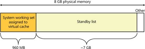
Figure 11-3. Example in which most of physical memory is being used by the file cache
Because the total amount of file data cached includes the system working set, modified page list, and standby list—the sizes of which are all controlled by the memory manager—it is in a sense the real cache manager. The cache manager subsystem simply provides convenient interfaces for accessing file data through the memory manager. It also plays an important role with its read-ahead and write-behind policies in influencing what data the memory manager keeps present in physical memory, as well as with managing system virtual address views of the space.
To try to accurately reflect the total amount of file data that’s cached on a system, Task Manager shows a value named Cache in its performance view that reflects the combined size of the system working set, standby list, and modified page list. Process Explorer, on the other hand, breaks up these values into Cache WS (system cache working set), Standby, and Modified. Figure 11-4 shows the system information view in Process Explorer and the Cache WS value in the Physical Memory area in the lower left of the figure, as well as the size of the standby and modified lists in the Paging Lists area near the middle of the figure. Note that the Cache value in Task Manager also includes the Paged WS, Kernel WS, and Driver WS values shown in Process Explorer. When these values were chosen, the vast majority of System WS came from the Cache WS. This is no longer the case today, but the anachronism remains in Task Manager.
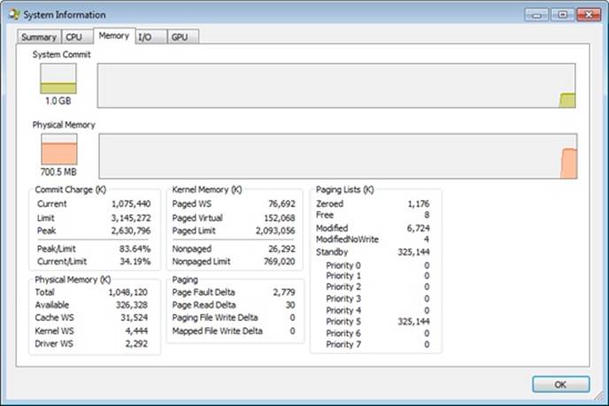
Figure 11-4. Process Explorer’s System Information dialog box
Cache Data Structures
The cache manager uses the following data structures to keep track of cached files:
§ Each 256-KB slot in the system cache is described by a VACB.
§ Each separately opened cached file has a private cache map, which contains information used to control read-ahead (discussed later in the chapter).
§ Each cached file has a single shared cache map structure, which points to slots in the system cache that contain mapped views of the file.
These structures and their relationships are described in the next sections.
Systemwide Cache Data Structures
As previously described, the cache manager keeps track of the state of the views in the system cache by using an array of data structures called virtual address control block (VACB) arrays that are stored in nonpaged pool. On a 32-bit system, each VACB is 32 bytes in size and a VACB array is 128 KB, resulting in 4,096 VACBs per array. On a 64-bit system, a VACB is 64 bytes, resulting in 2,048 VACBs per array. The cache manager allocates the initial VACB array during system initialization and links it into the systemwide list of VACB arrays calledCcVacbArrays. Each VACB represents one 256-KB view in the system cache, as shown in Figure 11-5. The structure of a VACB is shown in Figure 11-6.
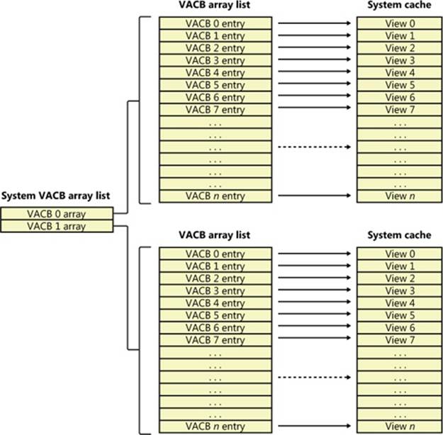
Figure 11-5. System VACB array
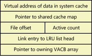
Figure 11-6. VACB structure
Additionally, each VACB array is composed of two kinds of VACB: low priority mapping VACBs and high priority mapping VACBs. The system allocates 64 initial high priority VACBs for each VACB array. High priority VACBs have the distinction of having their viewspreallocated from system address space. When the memory manager has no views to give to the cache manager at the time of mapping some data, and if the mapping request is marked as high priority, the cache manager will use one of the preallocated views present in a high priority VACB. It uses these high priority VACBs, for example, for critical file system metadata as well as for purging data from the cache. After high priority VACBs are gone, however, any operation requiring a VACB view will fail with insufficient resources. Typically, the mapping priority is set to the default of low, but by using the PIN_HIGH_PRIORITY flag when pinning (described later) cached data, file systems can request a high priority VACB to be used instead, if one is needed.
As you can see in Figure 11-6, the first field in a VACB is the virtual address of the data in the system cache. The second field is a pointer to the shared cache map structure, which identifies which file is cached. The third field identifies the offset within the file at which the view begins (always based on 256-KB granularity). Given this granularity, the bottom 16 bits of the file offset will always be zero, so those bits are reused to store the number of references to the view—that is, how many active reads or writes are accessing the view. The fourth field links the VACB into a list of least-recently-used (LRU) VACBs when the cache manager frees the VACB; the cache manager first checks this list when allocating a new VACB. Finally, the fifth field links this VACB to the VACB array header representing the array in which the VACB is stored.
During an I/O operation on a file, the file’s VACB reference count is incremented, and then it’s decremented when the I/O operation is over. When the reference count is nonzero the VACB is active. For access to file system metadata, the active count represents how many file system drivers have the pages in that view locked into memory.
EXPERIMENT: LOOKING AT VACBS AND VACB STATISTICS
The cache manager internally keeps track of various values that are useful to developers and support engineers when debugging crash dumps. All these debugging variables start with the CcDbg prefix, which makes it easy to see the whole list, thanks to the x command:
lkd> x nt!*ccdbg*
8194ba84 nt!CcDbgNumberOfCcUnmapInactiveViews = <no type information>
8197c740 nt!CcDbgNumberOfFailedMappingsDueToVacbSpace = <no type information>
8197c730 nt!CcDbgNumberOfFailedBitmapAllocations = <no type information>
8197c73c nt!CcDbgNumberOfFailedHighPriorityMappingsDueToMmResources =
<no type information>
...
Some systems may show differences in variable names due to 32-bit versus 64-bit implementations. The exact variable names are irrelevant in this experiment—focus instead on the methodology that is explained. Using these variables and your knowledge of the VACB array header data structures, you can use the kernel debugger to list all the VACB array headers. TheCcVacbArrays variable is an array of pointers to VACB array headers, which you dereference in order to dump the contents of the _VACB_ARRAY_HEADERs. First, obtain the highest array index:
lkd> dd nt!CcVacbArraysHighestUsedIndex l 1
8194ba7c 00000000
And now you can dereference each index until the maximum index. On this system (and this is the norm), the highest index is 0, which means there’s only one header to dereference:
lkd> ?? (*((nt!_VACB_ARRAY_HEADER***)@@(nt!CcVacbArrays)))[0]
struct _VACB_ARRAY_HEADER * 0x8315b000
+0x000 VacbArrayIndex : 0
+0x004 MappingCount : 0x5ab
+0x008 HighestMappedIndex : 0x9a9
+0x00c Reserved : 0
If there were more, you could change the array index at the end of the command with a higher number, until you reached the highest used index. The output shows that the system has only one VACB array with 1,451 (0x5ab) active VACBs.
Finally, the CcNumberOfFreeVacbs variable stores the number of VACBs on the free VACB list. Dumping this variable on the system used for the experiment results in 2,645 (0xa55):
lkd> dd nt!CcNumberOfFreeVacbs l 1
8197c768 00000a55
As expected, the sum of the free (0x5ab—1,451 decimal) and active VACBs (0xa55—2,645 decimal) on a 32-bit system with one VACB array equals 4,096, the number of VACBs in one VACB array. If the system were to run out of free VACBs, the cache manager would try to allocate a new VACB array. Because of the volatile nature of this experiment, your system may create and/or free additional VACBs between the two steps (dumping the active and then the free VACBs). This might cause your total of free and active VACBs to not match exactly 4,096. Try quickly repeating the experiment a couple of times if this happens, although you may never get stale numbers, especially if there is lots of file system activity on the system.
Per-File Cache Data Structures
Each open handle to a file has a corresponding file object. (File objects are explained in detail in Chapter 8.) If the file is cached, the file object points to a private cache map structure that contains the location of the last two reads so that the cache manager can perform intelligent read-ahead (described later, in the section Intelligent Read-Ahead). In addition, all the private cache maps for open instances of a file are linked together.
Each cached file (as opposed to file object) has a shared cache map structure that describes the state of the cached file, including its size and its valid data length. (The function of the valid data length field is explained in the section Write-Back Caching and Lazy Writing.) The shared cache map also points to the section object (maintained by the memory manager and which describes the file’s mapping into virtual memory), the list of private cache maps associated with that file, and any VACBs that describe currently mapped views of the file in the system cache. (See Chapter 10 for more about section object pointers.) The relationships among these per-file cache data structures are illustrated in Figure 11-7.
When asked to read from a particular file, the cache manager must determine the answers to two questions:
1. Is the file in the cache?
2. If so, which VACB, if any, refers to the requested location?
In other words, the cache manager must find out whether a view of the file at the desired address is mapped into the system cache. If no VACB contains the desired file offset, the requested data isn’t currently mapped into the system cache.
To keep track of which views for a given file are mapped into the system cache, the cache manager maintains an array of pointers to VACBs, which is known as the VACB index array. The first entry in the VACB index array refers to the first 256 KB of the file, the second entry to the second 256 KB, and so on. The diagram in Figure 11-8 shows four different sections from three different files that are currently mapped into the system cache.
When a process accesses a particular file in a given location, the cache manager looks in the appropriate entry in the file’s VACB index array to see whether the requested data has been mapped into the cache. If the array entry is nonzero (and hence contains a pointer to a VACB), the area of the file being referenced is in the cache. The VACB, in turn, points to the location in the system cache where the view of the file is mapped. If the entry is zero, the cache manager must find a free slot in the system cache (and therefore a free VACB) to map the required view.
As a size optimization, the shared cache map contains a VACB index array that is four entries in size. Because each VACB describes 256 KB, the entries in this small, fixed-size index array can point to VACB array entries that together describe a file of up to 1 MB. If a file is larger than 1 MB, a separate VACB index array is allocated from nonpaged pool, based on the size of the file divided by 256 KB and rounded up in the case of a remainder. The shared cache map then points to this separate structure.
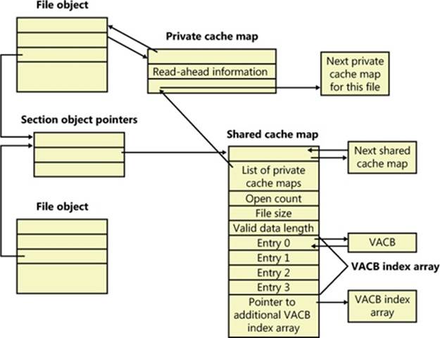
Figure 11-7. Per-file cache data structures
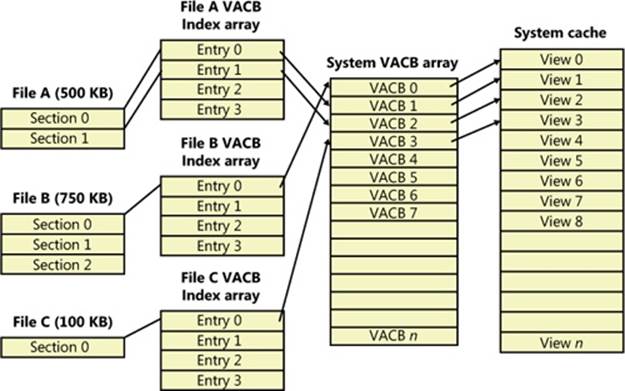
Figure 11-8. VACB index arrays
As a further optimization, the VACB index array allocated from nonpaged pool becomes a sparse multilevel index array if the file is larger than 32 MB, where each index array consists of 128 entries. You can calculate the number of levels required for a file with the following formula:
(Number of bits required to represent file size – 18) / 7
Round the result of the equation up to the next whole number. The value 18 in the equation comes from the fact that a VACB represents 256 KB, and 256 KB is 2^18. The value 7 comes from the fact that each level in the array has 128 entries and 2^7 is 128. Thus, a file that has a size that is the maximum that can be described with 63 bits (the largest size the cache manager supports) would require only seven levels. The array is sparse because the only branches that the cache manager allocates are ones for which there are active views at the lowest-level index array. Figure 11-9 shows an example of a multilevel VACB array for a sparse file that is large enough to require three levels.
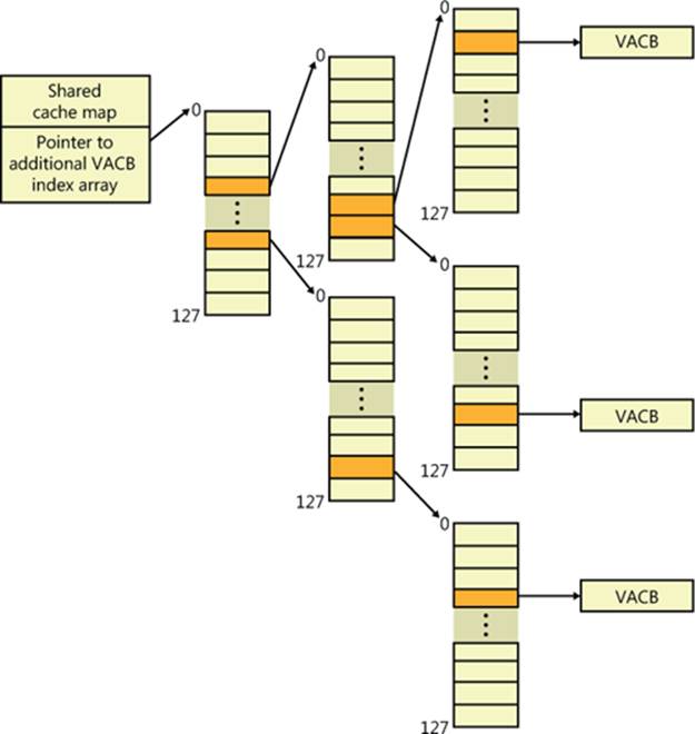
Figure 11-9. Multilevel VACB arrays
This scheme is required to efficiently handle sparse files that might have extremely large file sizes with only a small fraction of valid data because only enough of the array is allocated to handle the currently mapped views of a file. For example, a 32-GB sparse file for which only 256 KB is mapped into the cache’s virtual address space would require a VACB array with three allocated index arrays because only one branch of the array has a mapping and a 32-GB (235 bytes) file requires a three-level array. If the cache manager didn’t use the multilevel VACB index array optimization for this file, it would have to allocate a VACB index array with 128,000 entries, or the equivalent of 1,000 VACB index arrays.
EXPERIMENT: LOOKING AT SHARED AND PRIVATE CACHE MAPS
You can use the kernel debugger’s dt command to look at the shared and private cache map data structure definitions and examine the structures on a live system. First, execute the !filecache command and locate an entry in the VACB output with a file name you recognize. In this example, the file is the System event log:
8742a008 120 160 0 0 System.evtx
The first address is that of a control area data structure, which the memory manager uses to keep track of an address range. (See Chapter 10 for more information.) The control area stores the pointer to the file object that corresponds to the view in the cache. A file object identifies an instance of an open file. Execute the following command using the address of the control area of the entry you identified to see the control area structure:
lkd> !ca 8742a008
ControlArea @ 87cd7248
Segment 824157e0 Flink 00000000 Blink 00000000
Section Ref 1 Pfn Ref 1117 Mapped Views 3
User Ref 0 WaitForDel 0 Flush Count 0
File Object 87bcab60 ModWriteCount 0 System Views 3
WritableRefs 0
Flags (c080) File WasPurged Accessed
\Windows\System32\winevt\Logs\System.evtx
...
Next look at the file object referenced by the control area with this command:
lkd> dt nt!_FILE_OBJECT 87bcab60
+0x000 Type : 0n5
+0x002 Size : 0n128
+0x004 DeviceObject : 0x86a4c4d0 _DEVICE_OBJECT
+0x008 Vpb : 0x86a0c270 _VPB
+0x00c FsContext : 0x93b2a8e0 Void
+0x010 FsContext2 : 0x93b2aa38 Void
+0x014 SectionObjectPointer : 0x87c1b6f0 _SECTION_OBJECT_POINTERS
+0x018 PrivateCacheMap : 0x87cd59e8 Void
+0x01c FinalStatus : 0n0
+0x020 RelatedFileObject : (null)
+0x024 LockOperation : 0 ''
...
The private cache map is at offset 0x18:
lkd> dt nt!_PRIVATE_CACHE_MAP 0x87cd59e8
+0x000 NodeTypeCode : 0n766
+0x000 Flags : _PRIVATE_CACHE_MAP_FLAGS
+0x000 UlongFlags : 0x1402fe
+0x004 ReadAheadMask : 0xffff
+0x008 FileObject : 0x87bcab60 _FILE_OBJECT
+0x010 FileOffset1 : _LARGE_INTEGER 0x1000
+0x018 BeyondLastByte1 : _LARGE_INTEGER 0x1080
+0x020 FileOffset2 : _LARGE_INTEGER 0x1000
+0x028 BeyondLastByte2 : _LARGE_INTEGER 0x1080
...
Finally, you can locate the shared cache map in the SectionObjectPointer field of the file object and then view its contents:
lkd> dt nt!_SECTION_OBJECT_POINTERS 0x87c1b6f0
+0x000 DataSectionObject : 0x87cd7248
+0x004 SharedCacheMap : 0x87cd58f8
+0x008 ImageSectionObject : (null)
lkd> dt nt!_SHARED_CACHE_MAP 0x87cd58f8
+0x000 NodeTypeCode : 767
+0x002 NodeByteSize : 0n352
+0x004 OpenCount : 1
+0x008 FileSize : _LARGE_INTEGER 0x1211000
+0x010 BcbList : _LIST_ENTRY [ 0x87cd5908 - 0x87cd5908 ]
+0x018 SectionSize : _LARGE_INTEGER 0x1300000
+0x020 ValidDataLength : _LARGE_INTEGER 0x1116200
+0x028 ValidDataGoal : _LARGE_INTEGER 0x1116200
+0x030 InitialVacbs : [4] (null)
+0x040 Vacbs : 0x87dc3a20 -> 0x85ba9df0 _VACB
+0x044 FileObjectFastRef : _EX_FAST_REF
+0x048 VacbLock : _EX_PUSH_LOCK
...
Alternatively, you can use the !fileobj command to look up and display much of this information automatically. For example, using this command on the same file object referenced earlier results in the following output:
lkd> !fileobj 87bcab60
\Windows\System32\winevt\Logs\System.evtx
Device Object: 0x86a4c4d0 \Driver\volmgr
Vpb: 0x86a0c270
Event signalled
Access: Read Write SharedRead
Flags: 0xc3042
Synchronous IO
Cache Supported
Modified
Size Changed
Handle Created
Fast IO Read
FsContext: 0x93b2a8e0 FsContext2: 0x93b2aa38
Private Cache Map: 0x87cd59e8
CurrentByteOffset: 1116180
Cache Data:
Section Object Pointers: 87c1b6f0
Shared Cache Map: 87cd58f8 File Offset: 1116180 in VACB number 44
Vacb: 85ba9d90
Your data is at: 82756180
File System Interfaces
The first time a file’s data is accessed for a read or write operation, the file system driver is responsible for determining whether some part of the file is mapped in the system cache. If it’s not, the file system driver must call the CcInitializeCacheMap function to set up the per-file data structures described in the preceding section.
Once a file is set up for cached access, the file system driver calls one of several functions to access the data in the file. There are three primary methods for accessing cached data, each intended for a specific situation:
§ The copy method copies user data between cache buffers in system space and a process buffer in user space.
§ The mapping and pinning method uses virtual addresses to read and write data directly from and to cache buffers.
§ The physical memory access method uses physical addresses to read and write data directly from and to cache buffers.
File system drivers must provide two versions of the file read operation—cached and noncached—to prevent an infinite loop when the memory manager processes a page fault. When the memory manager resolves a page fault by calling the file system to retrieve data from the file (via the device driver, of course), it must specify this noncached read operation by setting the “no cache” flag in the IRP.
Figure 11-10 illustrates the typical interactions between the cache manager, the memory manager, and file system drivers in response to user read or write file I/O. The cache manager is invoked by a file system through the copy interfaces (the CcCopyRead and CcCopyWrite paths). To process a CcFastCopyRead or CcCopyRead read, for example, the cache manager creates a view in the cache to map a portion of the file being read and reads the file data into the user buffer by copying from the view. The copy operation generates page faults as it accesses each previously invalid page in the view, and in response the memory manager initiates noncached I/O into the file system driver to retrieve the data corresponding to the part of the file mapped to the page that faulted.
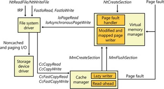
Figure 11-10. File system interaction with cache and memory managers
The next three sections explain these cache access mechanisms, their purpose, and how they’re used.
Copying to and from the Cache
Because the system cache is in system space, it is mapped into the address space of every process. As with all system space pages, however, cache pages aren’t accessible from user mode because that would be a potential security hole. (For example, a process might not have the rights to read a file whose data is currently contained in some part of the system cache.) Thus, user application file reads and writes to cached files must be serviced by kernel-mode routines that copy data between the cache’s buffers in system space and the application’s buffers residing in the process address space.
Caching with the Mapping and Pinning Interfaces
Just as user applications read and write data in files on a disk, file system drivers need to read and write the data that describes the files themselves (the metadata, or volume structure data). Because the file system drivers run in kernel mode, however, they could, if the cache manager were properly informed, modify data directly in the system cache. To permit this optimization, the cache manager provides functions that permit the file system drivers to find where in virtual memory the file system metadata resides, thus allowing direct modification without the use of intermediary buffers.
If a file system driver needs to read file system metadata in the cache, it calls the cache manager’s mapping interface to obtain the virtual address of the desired data. The cache manager touches all the requested pages to bring them into memory and then returns control to the file system driver. The file system driver can then access the data directly.
If the file system driver needs to modify cache pages, it calls the cache manager’s pinning services, which keep the pages active in virtual memory so that they cannot be reclaimed. The pages aren’t actually locked into memory (such as when a device driver locks pages for direct memory access transfers). Most of the time, a file system driver will mark its metadata stream “no write”, which instructs the memory manager’s mapped page writer (explained in Chapter 10) to not write the pages to disk until explicitly told to do so. When the file system driver unpins (releases) them, the cache manager releases its resources so that it can lazily flush any changes to disk and release the cache view that the metadata occupied.
The mapping and pinning interfaces solve one thorny problem of implementing a file system: buffer management. Without directly manipulating cached metadata, a file system must predict the maximum number of buffers it will need when updating a volume’s structure. By allowing the file system to access and update its metadata directly in the cache, the cache manager eliminates the need for buffers, simply updating the volume structure in the virtual memory the memory manager provides. The only limitation the file system encounters is the amount of available memory.
Caching with the Direct Memory Access Interfaces
In addition to the mapping and pinning interfaces used to access metadata directly in the cache, the cache manager provides a third interface to cached data: direct memory access (DMA). The DMA functions are used to read from or write to cache pages without intervening buffers, such as when a network file system is doing a transfer over the network.
The DMA interface returns to the file system the physical addresses of cached user data (rather than the virtual addresses, which the mapping and pinning interfaces return), which can then be used to transfer data directly from physical memory to a network device. Although small amounts of data (1 KB to 2 KB) can use the usual buffer-based copying interfaces, for larger transfers the DMA interface can result in significant performance improvements for a network server processing file requests from remote systems. To describe these references to physical memory, a memory descriptor list (MDL) is used. (MDLs are introduced in Chapter 10.)
Fast I/O
Whenever possible, reads and writes to cached files are handled by a high-speed mechanism named fast I/O. Fast I/O is a means of reading or writing a cached file without going through the work of generating an IRP, as described in Chapter 8. With fast I/O, the I/O manager calls the file system driver’s fast I/O routine to see whether I/O can be satisfied directly from the cache manager without generating an IRP.
Because the cache manager is architected on top of the virtual memory subsystem, file system drivers can use the cache manager to access file data simply by copying to or from pages mapped to the actual file being referenced without going through the overhead of generating an IRP.
Fast I/O doesn’t always occur. For example, the first read or write to a file requires setting up the file for caching (mapping the file into the cache and setting up the cache data structures, as explained earlier in the section Cache Data Structures). Also, if the caller specified anasynchronous read or write, fast I/O isn’t used because the caller might be stalled during paging I/O operations required to satisfy the buffer copy to or from the system cache and thus not really providing the requested asynchronous I/O operation. But even on a synchronous I/O, the file system driver might decide that it can’t process the I/O operation by using the fast I/O mechanism, say, for example, if the file in question has a locked range of bytes (as a result of calls to the Windows LockFile and UnlockFile functions). Because the cache manager doesn’t know what parts of which files are locked, the file system driver must check the validity of the read or write, which requires generating an IRP. The decision tree for fast I/O is shown in Figure 11-11.
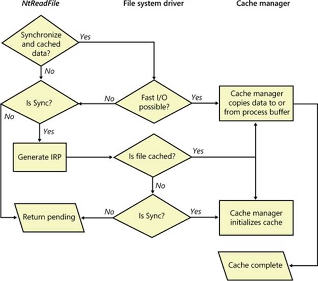
Figure 11-11. Fast I/O decision tree
These steps are involved in servicing a read or a write with fast I/O:
1. A thread performs a read or write operation.
2. If the file is cached and the I/O is synchronous, the request passes to the fast I/O entry point of the file system driver stack. If the file isn’t cached, the file system driver sets up the file for caching so that the next time, fast I/O can be used to satisfy a read or write request.
3. If the file system driver’s fast I/O routine determines that fast I/O is possible, it calls the cache manager’s read or write routine to access the file data directly in the cache. (If fast I/O isn’t possible, the file system driver returns to the I/O system, which then generates an IRP for the I/O and eventually calls the file system’s regular read routine.)
4. The cache manager translates the supplied file offset into a virtual address in the cache.
5. For reads, the cache manager copies the data from the cache into the buffer of the process requesting it; for writes, it copies the data from the buffer to the cache.
6. One of the following actions occurs:
o For reads where FILE_FLAG_RANDOM_ACCESS wasn’t specified when the file was opened, the read-ahead information in the caller’s private cache map is updated. Read-ahead may also be queued for files for which the FO_RANDOM_ACCESS flag is not specified.
o For writes, the dirty bit of any modified page in the cache is set so that the lazy writer will know to flush it to disk.
o For write-through files, any modifications are flushed to disk.
Read-Ahead and Write-Behind
In this section, you’ll see how the cache manager implements reading and writing file data on behalf of file system drivers. Keep in mind that the cache manager is involved in file I/O only when a file is opened without the FILE_FLAG_NO_BUFFERING flag and then read from or written to using the Windows I/O functions (for example, using the Windows ReadFile and WriteFile functions). Mapped files don’t go through the cache manager, nor do files opened with the FILE_FLAG_NO_BUFFERING flag set.
NOTE
When an application uses the FILE_FLAG_NO_BUFFERING flag to open a file, its file I/O must start at device-aligned offsets and be of sizes that are a multiple of the alignment size; its input and output buffers must also be device-aligned virtual addresses. For file systems, this usually corresponds to the sector size (512 bytes on NTFS, typically, and 2,048 bytes on CDFS). One of the benefits of the cache manager, apart from the actual caching performance, is the fact that it performs intermediate buffering to allow arbitrarily aligned and sized I/O.
Intelligent Read-Ahead
The cache manager uses the principle of spatial locality to perform intelligent read-ahead by predicting what data the calling process is likely to read next based on the data that it is reading currently. Because the system cache is based on virtual addresses, which are contiguous for a particular file, it doesn’t matter whether they’re juxtaposed in physical memory. File read-ahead for logical block caching is more complex and requires tight cooperation between file system drivers and the block cache because that cache system is based on the relative positions of the accessed data on the disk, and, of course, files aren’t necessarily stored contiguously on disk. You can examine read-ahead activity by using the Cache: Read Aheads/sec performance counter or the CcReadAheadIos system variable.
Reading the next block of a file that is being accessed sequentially provides an obvious performance improvement, with the disadvantage that it will cause head seeks. To extend read-ahead benefits to cases of strided data accesses (both forward and backward through a file), the cache manager maintains a history of the last two read requests in the private cache map for the file handle being accessed, a method known as asynchronous read-ahead with history. If a pattern can be determined from the caller’s apparently random reads, the cache manager extrapolates it. For example, if the caller reads page 4000 and then page 3000, the cache manager assumes that the next page the caller will require is page 2000 and prereads it.
NOTE
Although a caller must issue a minimum of three read operations to establish a predictable sequence, only two are stored in the private cache map.
To make read-ahead even more efficient, the Win32 CreateFile function provides a flag indicating forward sequential file access: FILE_FLAG_SEQUENTIAL_SCAN. If this flag is set, the cache manager doesn’t keep a read history for the caller for prediction but instead performssequential read-ahead. However, as the file is read into the cache’s working set, the cache manager unmaps views of the file that are no longer active and, if they are unmodified, directs the memory manager to place the pages belonging to the unmapped views at the front of the standby list so that they will be quickly reused. It also reads ahead two times as much data (2 MB instead of 1 MB, for example). As the caller continues reading, the cache manager prereads additional blocks of data, always staying about one read (of the size of the current read) ahead of the caller.
The cache manager’s read-ahead is asynchronous because it is performed in a thread separate from the caller’s thread and proceeds concurrently with the caller’s execution. When called to retrieve cached data, the cache manager first accesses the requested virtual page to satisfy the request and then queues an additional I/O request to retrieve additional data to a system worker thread. The worker thread then executes in the background, reading additional data in anticipation of the caller’s next read request. The preread pages are faulted into memory while the program continues executing so that when the caller requests the data it’s already in memory.
For applications that have no predictable read pattern, the FILE_FLAG_RANDOM_ACCESS flag can be specified when the CreateFile function is called. This flag instructs the cache manager not to attempt to predict where the application is reading next and thus disables read-ahead. The flag also stops the cache manager from aggressively unmapping views of the file as the file is accessed so as to minimize the mapping/unmapping activity for the file when the application revisits portions of the file.
Write-Back Caching and Lazy Writing
The cache manager implements a write-back cache with lazy write. This means that data written to files is first stored in memory in cache pages and then written to disk later. Thus, write operations are allowed to accumulate for a short time and are then flushed to disk all at once, reducing the overall number of disk I/O operations.
The cache manager must explicitly call the memory manager to flush cache pages because otherwise the memory manager writes memory contents to disk only when demand for physical memory exceeds supply, as is appropriate for volatile data. Cached file data, however, representsnonvolatile disk data. If a process modifies cached data, the user expects the contents to be reflected on disk in a timely manner.
Additionally, the cache manager has the ability to veto the memory manager’s mapped writer thread. Since the modified list (see Chapter 10 for more information) is not sorted in logical block address (LBA) order, the cache manager’s attempts to cluster pages for larger sequential I/Os to the disk are not always successful and actually cause repeated seeks. To combat this effect, the cache manager has the ability to aggressively veto the mapped writer thread and stream out writes in virtual byte offset (VBO) order, which is much closer to the LBA order on disk. Since the cache manager now owns these writes, it can also apply its own scheduling and throttling algorithms to prefer read-ahead over write-behind and impact the system less.
The decision about how often to flush the cache is an important one. If the cache is flushed too frequently, system performance will be slowed by unnecessary I/O. If the cache is flushed too rarely, you risk losing modified file data in the cases of a system failure (a loss especially irritating to users who know that they asked the application to save the changes) and running out of physical memory (because it’s being used by an excess of modified pages).
To balance these concerns, once per second the cache manager’s lazy writer function executes on a system worker thread and queues one-eighth of the dirty pages in the system cache to be written to disk. If the rate at which dirty pages are being produced is greater than the amount the lazy writer had determined it should write, the lazy writer writes an additional number of dirty pages that it calculates are necessary to match that rate. System worker threads from the systemwide critical worker thread pool actually perform the I/O operations. The lazy writer is also aware of when the memory manager’s mapped page writer is already performing a flush. In these cases, it delays its write-back capabilities to the same stream to avoid a situation where two flushers are writing to the same file.
NOTE
The cache manager provides a means for file system drivers to track when and how much data has been written to a file. After the lazy writer flushes dirty pages to the disk, the cache manager notifies the file system, instructing it to update its view of the valid data length for the file. (The cache manager and file systems separately track in memory the valid data length for a file.)
EXPERIMENT: WATCHING THE CACHE MANAGER IN ACTION
In this experiment, we’ll use Process Monitor to view the underlying file system activity, including cache manager read-ahead and write-behind, when Windows Explorer copies a large file (in this example, a CD-ROM image) from one local directory to another.
First, configure Process Monitor’s filter to include the source and destination file paths, the Explorer.exe and System processes, and the ReadFile and WriteFile operations. In this example, the C:\Users\Administrator\Downloads\dump.dmp file was copied to C:\dump.dmp, so the filter is configured as follows:
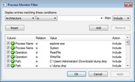
You should see a Process Monitor trace like the one shown here after you copy the file:
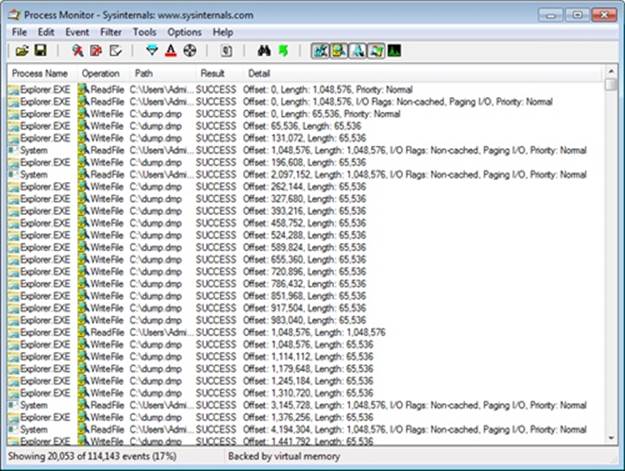
The first few entries show the initial I/O processing performed by the copy engine and the first cache manager operations. Here are some of the things that you can see:
§ The initial 1-MB cached read from Explorer at the first entry. The size of this read depends on an internal matrix calculation based on the file size and can vary from 128 KB to 1 MB. Because this file was large, the copy engine chose 1 MB.
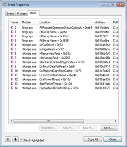
§ The 1-MB read is followed by another 1-MB noncached read. Noncached reads typically indicate activity due to page faults or cache manager access. A closer look at the stack trace for these events, which you can see by double-clicking an entry and choosing the Stack tab, reveals that indeed the CcCopyRead cache manager routine, which is called by the NTFS driver’s read routine, causes the memory manager to fault the source data into physical memory:
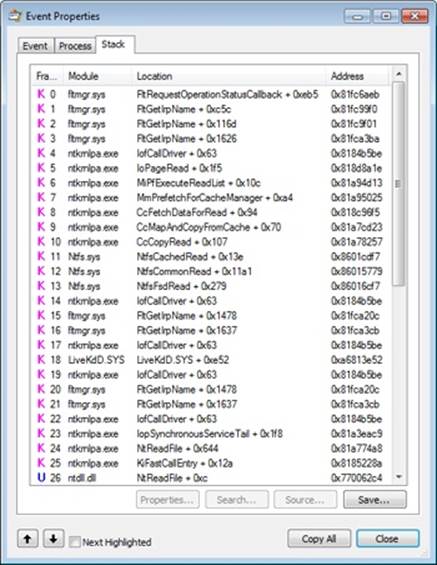
§ After this 1-MB page fault I/O, the cache manager’s read-ahead mechanism starts reading the file, which includes the System process’s subsequent noncached 1-MB read at the 1-MB offset. Because of the file size and Explorer’s read I/O sizes, the cache manager chose 1 MB as the optimal read-ahead size. The stack trace for one of the read-ahead operations, shown next, confirms that one of the cache manager’s worker threads is performing the read-ahead.
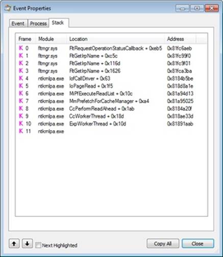
After this point, Explorer’s 1-MB reads aren’t followed by page faults, because the read-ahead thread stays ahead of Explorer, prefetching the file data with its 1-MB noncached reads. However, every once in a while, the read-ahead thread is not able to pick up enough data in time, and clustered page faults do occur, which appear as Synchronous Paging I/O.
If you look at the stack for these entries, you’ll see that instead of MmPrefetchForCacheManager, the MmAccessFault/MiIssueHardFault routines are called.
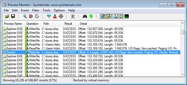
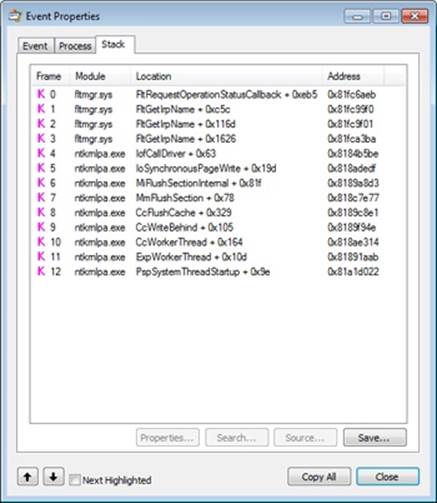
As soon as it starts reading, Explorer also starts performing writes to the destination file. These are sequential, cached 64-KB writes. After about 132 MB of reads, the first WriteFile operation from the System process occurs, shown here:
The write operation’s stack trace, shown here, indicates that the memory manager’s mapped page writer thread was actually responsible for the write:
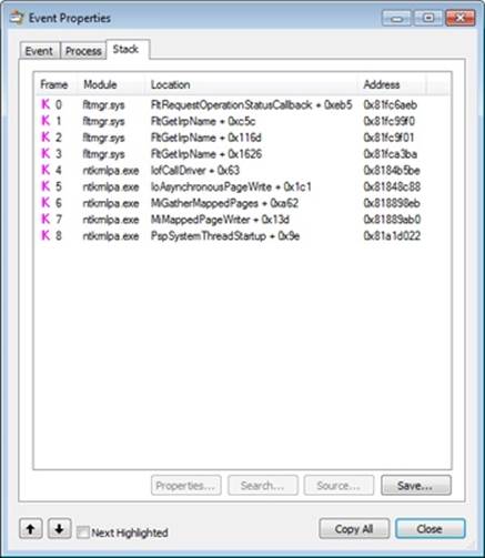
This occurs because for the first couple of megabytes of data, the cache manager hadn’t started performing write-behind, so the memory manager’s mapped page writer began flushing the modified destination file data. (See Chapter 10 for more information on the mapped page writer.)
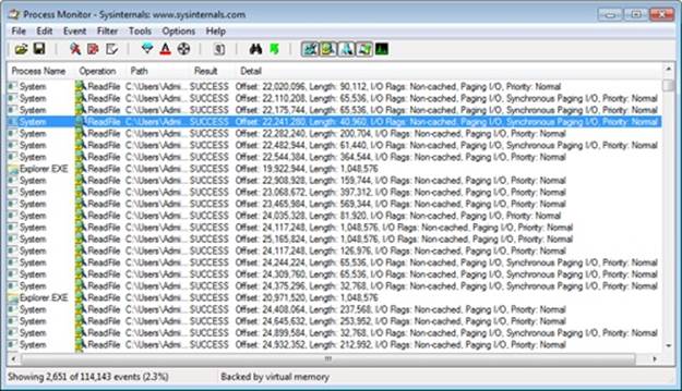
To get a clearer view of the cache manager operations, remove Explorer from the Process Monitor’s filter so that only the System process operations are visible, as shown next.
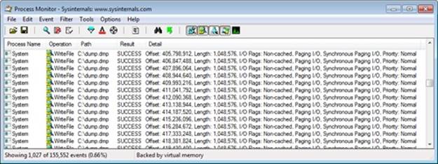
With this view, it’s much easier to see the cache manager’s 1-MB write-behind operations (the maximum write sizes are 1 MB on client versions of Windows and 32 MB on server versions; this experiment was performed on a client system). The stack trace for one of the write-behind operations, shown here, verifies that a cache manager worker thread is performing write-behind:
As an added experiment, try repeating this process with a remote copy instead (from one Windows system to another) and by copying files of varying sizes. You’ll notice some different behaviors by the copy engine and the cache manager, both on the receiving and sending sides.
Disabling Lazy Writing for a File
If you create a temporary file by specifying the flag FILE_ATTRIBUTE_TEMPORARY in a call to the Windows CreateFile function, the lazy writer won’t write dirty pages to the disk unless there is a severe shortage of physical memory or the file is explicitly flushed. This characteristic of the lazy writer improves system performance—the lazy writer doesn’t immediately write data to a disk that might ultimately be discarded. Applications usually delete temporary files soon after closing them.
Forcing the Cache to Write Through to Disk
Because some applications can’t tolerate even momentary delays between writing a file and seeing the updates on disk, the cache manager also supports write-through caching on a per–file object basis; changes are written to disk as soon as they’re made. To turn on write-through caching, set the FILE_FLAG_WRITE_THROUGH flag in the call to the CreateFile function. Alternatively, a thread can explicitly flush an open file, by using the Windows FlushFileBuffers function, when it reaches a point at which the data needs to be written to disk.
Flushing Mapped Files
If the lazy writer must write data to disk from a view that’s also mapped into another process’s address space, the situation becomes a little more complicated, because the cache manager will only know about the pages it has modified. (Pages modified by another process are known only to that process because the modified bit in the page table entries for modified pages is kept in the process private page tables.) To address this situation, the memory manager informs the cache manager when a user maps a file. When such a file is flushed in the cache (for example, as a result of a call to the Windows FlushFileBuffers function), the cache manager writes the dirty pages in the cache and then checks to see whether the file is also mapped by another process. When the cache manager sees that the file is, the cache manager then flushes the entire view of the section to write out pages that the second process might have modified. If a user maps a view of a file that is also open in the cache, when the view is unmapped, the modified pages are marked as dirty so that when the lazy writer thread later flushes the view, those dirty pages will be written to disk. This procedure works as long as the sequence occurs in the following order:
1. A user unmaps the view.
2. A process flushes file buffers.
If this sequence isn’t followed, you can’t predict which pages will be written to disk.
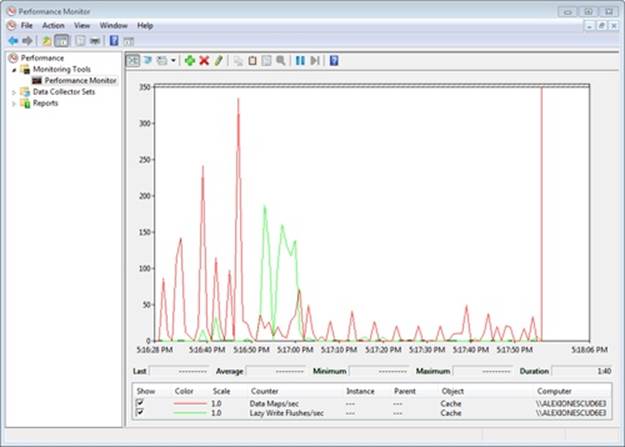
EXPERIMENT: WATCHING CACHE FLUSHES
You can see the cache manager map views into the system cache and flush pages to disk by running the Performance Monitor and adding the Data Maps/sec and Lazy Write Flushes/sec counters and then copying a large file from one location to another. The generally higher line in the following screen shot shows Data Maps/sec and the other shows Lazy Write Flushes/sec. During the file copy, Lazy Write Flushes/sec significantly increased.
Write Throttling
The file system and cache manager must determine whether a cached write request will affect system performance and then schedule any delayed writes. First the file system asks the cache manager whether a certain number of bytes can be written right now without hurting performance by using the CcCanIWrite function and blocking that write if necessary. For asynchronous I/O, the file system sets up a callback with the cache manager for automatically writing the bytes when writes are again permitted by calling CcDeferWrite. Otherwise, it just blocks and waits on CcCanIWrite to continue. Once it’s notified of an impending write operation, the cache manager determines how many dirty pages are in the cache and how much physical memory is available. If few physical pages are free, the cache manager momentarily blocks the file system thread that’s requesting to write data to the cache. The cache manager’s lazy writer flushes some of the dirty pages to disk and then allows the blocked file system thread to continue. This write throttling prevents system performance from degrading because of a lack of memory when a file system or network server issues a large write operation.
NOTE
The effects of write throttling are volume-aware, such that if a user is copying a large file on, say, a RAID-0 SSD while also transferring a document to a portable USB thumb drive, writes to the USB disk will not cause write throttling to occur on the SSD transfer.
The dirty page threshold is the number of pages that the system cache will allow to be dirty before throttling cached writers. This value is computed at system initialization time and depends on the product type (client or server). Two other values are also computed—the top dirty page threshold and the bottom dirty page threshold. Depending on memory consumption and the rate at which dirty pages are being processed, the lazy writer calls the internal function CcAdjustThrottle, which, on server systems, performs dynamic adjustment of the current threshold based on the calculated top and bottom values. This adjustment is made to preserve the read cache in cases of a heavy write load that will inevitably overrun the cache and become throttled. Table 11-1 lists the algorithms used to calculate the dirty page thresholds.
Table 11-1. Algorithms for Calculating the Dirty Page Thresholds
|
Product Type |
Dirty Page Threshold |
Top Dirty Page Threshold |
Bottom Dirty Page Threshold |
|
Client |
Physical pages / 8 |
Physical pages / 8 |
Physical pages / 8 |
|
Server |
Physical pages / 2 |
Physical pages / 2 |
Physical pages / 8 |
Write throttling is also useful for network redirectors transmitting data over slow communication lines. For example, suppose a local process writes a large amount of data to a remote file system over a 9600-baud line. The data isn’t written to the remote disk until the cache manager’s lazy writer flushes the cache. If the redirector has accumulated lots of dirty pages that are flushed to disk at once, the recipient could receive a network timeout before the data transfer completes. By using the CcSetDirtyPageThreshold function, the cache manager allows network redirectors to set a limit on the number of dirty cache pages they can tolerate (for each stream), thus preventing this scenario. By limiting the number of dirty pages, the redirector ensures that a cache flush operation won’t cause a network timeout.
EXPERIMENT: VIEWING THE WRITE-THROTTLE PARAMETERS
The !defwrites kernel debugger command dumps the values of the kernel variables the cache manager uses, including the number of dirty pages in the file cache (CcTotalDirtyPages), when determining whether it should throttle write operations:
lkd>
!defwrites
*** Cache Write Throttle Analysis ***
CcTotalDirtyPages: 39 ( 156 Kb)
CcDirtyPageThreshold: 32753 ( 131012 Kb)
MmAvailablePages: 81569 ( 326276 Kb)
MmThrottleTop: 450 ( 1800 Kb)
MmThrottleBottom: 80 ( 320 Kb)
MmModifiedPageListHead.Total: 4337 ( 17348 Kb)
Write throttles not engaged
This output shows that the number of dirty pages is far from the number that triggers write throttling (CcDirtyPageThreshold), so the system has not engaged in any write throttling.
System Threads
As mentioned earlier, the cache manager performs lazy write and read-ahead I/O operations by submitting requests to the common critical system worker thread pool. However, it does limit the use of these threads to one less than the total number of critical system worker threads for small and medium memory systems (two less than the total for large memory systems).
Internally, the cache manager organizes its work requests into four lists (though these are serviced by the same set of executive worker threads):
§ The express queue is used for read-ahead operations.
§ The regular queue is used for lazy write scans (for dirty data to flush), write-behinds, and lazy closes.
§ The fast teardown queue is used when the memory manager is waiting for the data section owned by the cache manager to be freed so that the file can be opened with an image section instead, which causes CcWriteBehind to flush the entire file and tear down the shared cache map.
§ The post tick queue is used for the cache manager to internally register for a notification after each “tick” of the lazy writer thread—in other words, at the end of each pass.
To keep track of the work items the worker threads need to perform, the cache manager creates its own internal per-processor look-aside list, a fixed-length list—one for each processor—of worker queue item structures. (Look-aside lists are discussed in Chapter 10.) The number of worker queue items depends on system size: 32 for small-memory systems, 64 for medium-memory systems, 128 for large-memory client systems, and 256 for large-memory server systems. For cross-processor performance, the cache manager also allocates a global look-aside list at the same sizes as just described.
Conclusion
The cache manager provides a high-speed, intelligent mechanism for reducing disk I/O and increasing overall system throughput. By caching on the basis of virtual blocks, the cache manager can perform intelligent read-ahead. By relying on the global memory manager’s mapped file primitive to access file data, the cache manager can provide the special fast I/O mechanism to reduce the CPU time required for read and write operations and also leave all matters related to physical memory management to the single Windows global memory manager, thus reducing code duplication and increasing efficiency.
All materials on the site are licensed Creative Commons Attribution-Sharealike 3.0 Unported CC BY-SA 3.0 & GNU Free Documentation License (GFDL)
If you are the copyright holder of any material contained on our site and intend to remove it, please contact our site administrator for approval.
© 2016-2026 All site design rights belong to S.Y.A.