Training Guide Installing and Configuring Windows Server 2012 R2 (2014)
Chapter 6. Network administration
The network is the foundation of an organization’s information system and enables computers and other devices to communicate with one another and with the Internet. Network services such as Dynamic Host Configuration Protocol (DHCP) servers and Domain Name System (DNS) servers simplify the configuration and management of IP address information and network names. To adequately fulfill these roles, such services must be available for clients that need them and be secure from attack.
Microsoft Windows Server 2012 and Windows Server 2012 R2 include enhancements to the DHCP Server and DNS Server roles that can help increase DHCP availability and safeguard DNS name resolution from being compromised or misused. Windows Server 2012 and Windows Server 2012 R2 also include added support for managing different aspects of Windows Server–based networks using Windows PowerShell. This chapter demonstrates how to implement these capabilities to ensure the availability and security of these critical network services and to manage Windows Server–based networks more efficiently. In addition, this chapter describes how to configure Internet Protocol version 6 (IPv6) networking and interoperability between IPv6 and IPv4.
Lessons in this chapter:
![]() Lesson 1: Ensuring DHCP availability
Lesson 1: Ensuring DHCP availability
![]() Lesson 2: Implementing DNSSEC
Lesson 2: Implementing DNSSEC
![]() Lesson 3: Managing networking using Windows PowerShell
Lesson 3: Managing networking using Windows PowerShell
![]() Lesson 4: Configuring IPv6/IPv4 interoperability
Lesson 4: Configuring IPv6/IPv4 interoperability
Before you begin
To complete the practice exercises in this chapter
![]() You should be familiar with basic networking concepts and administration tasks, including TCP/IP addressing concepts, how DHCP and DNS work, and how to configure DHCP and DNS servers using the Microsoft Management Console (MMC) snap-ins for these services.
You should be familiar with basic networking concepts and administration tasks, including TCP/IP addressing concepts, how DHCP and DNS work, and how to configure DHCP and DNS servers using the Microsoft Management Console (MMC) snap-ins for these services.
![]() You need to know how to deploy Windows Server 2012 R2, create an Active Directory forest, and add roles and features using Windows PowerShell.
You need to know how to deploy Windows Server 2012 R2, create an Active Directory forest, and add roles and features using Windows PowerShell.
![]() It will be helpful if you also have at least rudimentary knowledge of using Windows PowerShell on earlier versions of Windows Server.
It will be helpful if you also have at least rudimentary knowledge of using Windows PowerShell on earlier versions of Windows Server.
Lesson 1: Ensuring DHCP availability
DHCP provides a way to dynamically assign IP addresses and other parameters to hosts on a TCP/IP network. DHCP is designed to work automatically and relieves much of the management overhead associated with manually assigning static addresses to network hosts. DHCP servers play a critical role in ensuring hosts such as servers, clients, and printers on a TCP/IP network can communicate with one another.
Because DHCP leases addresses for only a specified amount of time, these leases need to be periodically renewed if the hosts are to continue communicating on the network. Although the DHCP lease renewal process has some degree of tolerance for DHCP server downtime built into it, ensuring the availability of DHCP servers on your network is nevertheless essential so that they can respond in a timely manner to lease renewal requests from network hosts. Otherwise, it is possible that some hosts might not be able to renew their addresses and therefore won’t be able to participate on the network.
After this lesson, you will be able to:
![]() Compare and contrast the different methods of ensuring DHCP availability on Windows Server–based networks.
Compare and contrast the different methods of ensuring DHCP availability on Windows Server–based networks.
![]() Explain the two failover modes of DHCP servers running Windows Server 2012 or Windows Server 2012 R2.
Explain the two failover modes of DHCP servers running Windows Server 2012 or Windows Server 2012 R2.
![]() Implement DHCP failover using the DHCP console.
Implement DHCP failover using the DHCP console.
![]() Describe the tasks involved in managing a DHCP failover solution.
Describe the tasks involved in managing a DHCP failover solution.
Estimated lesson time: 30 minutes
Previous approaches to implementing DHCP availability
Traditionally, DHCP server availability has been implemented on Windows Server–based networks using one or more of the following methods:
![]() Split scopes This approach involves splitting the IP address pool of a scope between two DHCP servers, typically by assigning the primary server 80 percent of the addresses in the scope and the secondary server the remaining 20 percent of the addresses. That way, if the primary server goes offline for any reason, DHCP clients on the subnet can still respond to lease renewal requests from the secondary server.
Split scopes This approach involves splitting the IP address pool of a scope between two DHCP servers, typically by assigning the primary server 80 percent of the addresses in the scope and the secondary server the remaining 20 percent of the addresses. That way, if the primary server goes offline for any reason, DHCP clients on the subnet can still respond to lease renewal requests from the secondary server.
![]() Server cluster This approach involves using the Failover Clustering feature of Windows Server 2008 or Windows Server 2008 R2 to cluster DHCP servers so that if the primary DHCP server in a cluster fails, the secondary server can take up the slack and continue leasing addresses to clients.
Server cluster This approach involves using the Failover Clustering feature of Windows Server 2008 or Windows Server 2008 R2 to cluster DHCP servers so that if the primary DHCP server in a cluster fails, the secondary server can take up the slack and continue leasing addresses to clients.
![]() Standby server This approach uses a hot standby DHCP server with scopes and options configured identically to your production DHCP server.
Standby server This approach uses a hot standby DHCP server with scopes and options configured identically to your production DHCP server.
Each of the preceding approaches has the following disadvantages, which make them of limited usefulness in ensuring DHCP server availability:
![]() The split-scope approach provides limited IP availability during outages. As a result, some clients might not receive addresses during a long-term DHCP server outage. In addition, if your DHCP server scope is currently running at high utilization—which is common for Internet Protocol version 4 (IPv4) networks—splitting the scope might not be feasible.
The split-scope approach provides limited IP availability during outages. As a result, some clients might not receive addresses during a long-term DHCP server outage. In addition, if your DHCP server scope is currently running at high utilization—which is common for Internet Protocol version 4 (IPv4) networks—splitting the scope might not be feasible.
![]() The DHCP server-cluster approach has only one DHCP database located on the cluster shared storage. That means there is a single point of failure for DHCP services on your network. In addition, implementing Failover Clustering requires relatively complex setup processes and maintenance tasks.
The DHCP server-cluster approach has only one DHCP database located on the cluster shared storage. That means there is a single point of failure for DHCP services on your network. In addition, implementing Failover Clustering requires relatively complex setup processes and maintenance tasks.
![]() The standby server approach requires both careful configuration of the standby DHCP server and manual intervention on the part of the administrator to ensure the failover transition when your production DHCP server fails or goes offline. There is additional complexity in this approach when DHCP is configured to automatically update DNS records, as is recommended in an Active Directory environment.
The standby server approach requires both careful configuration of the standby DHCP server and manual intervention on the part of the administrator to ensure the failover transition when your production DHCP server fails or goes offline. There is additional complexity in this approach when DHCP is configured to automatically update DNS records, as is recommended in an Active Directory environment.
Understanding DHCP failover

DHCP failover is a new approach to ensuring DHCP availability that was introduced in Windows Server 2012. With this approach, two DHCP servers can be configured to provide leases from the same pool of addresses. The two servers then replicate lease information between them, which enables one server to assume responsibility for providing leases to all clients on the subnet when the other server is unavailable. The goal of implementing this approach is to ensure DHCP service availability at all times, which is a key requirement for enterprise networks.
The current implementation of DHCP failover in Windows Server 2012 and Windows Server 2012 R2 has the following limitations:
![]() It only supports using a maximum of two DHCP servers.
It only supports using a maximum of two DHCP servers.
![]() The failover relationship is limited to IPv4 scopes and subnets.
The failover relationship is limited to IPv4 scopes and subnets.
You can implement DHCP server failover in two different configurations:
![]() Load-balance mode Leases are issued from both servers equally, which ensures availability and provides load balancing for your DHCP services. (This is the default DHCP server failover configuration.)
Load-balance mode Leases are issued from both servers equally, which ensures availability and provides load balancing for your DHCP services. (This is the default DHCP server failover configuration.)
![]() Hot-standby mode Leases are issued from the primary server until it fails, then the lease data is automatically replicated to the secondary server, which assumes the load.
Hot-standby mode Leases are issued from the primary server until it fails, then the lease data is automatically replicated to the secondary server, which assumes the load.
Load-balance mode
A typical scenario for implementing load-balance mode is when you want to have two DHCP servers at the same physical site. If the site has a single subnet, all you need to do is enable DHCP failover in its default configuration. If there are multiple subnets, deploy both DHCP servers in the same subnet, configure your routers as DHCP relay agents (or deploy additional DHCP relay agents in subnets), and enable DHCP server failover in its default configuration.
Hot-standby mode
When implementing hot-standby mode, you can configure a DHCP server so that it acts as the primary server for one subnet and as the secondary server for other subnets. One scenario in which you might implement this approach is in organizations that have a central hub site (typically, the data center at the head office) connected via wide area network (WAN) links to multiple remote branch-office sites. Figure 6-1 shows an example of an organization that has DHCP servers deployed at each branch office and at the head office. Branch-office servers are configured to lease addresses to clients at their branch offices, and the central server leases addresses to clients at the head office. Each branch-office server has a failover relationship with the central server, with the branch-office server assuming the role as primary and the central server as secondary. That way, if a DHCP server fails at a branch office, the central server can take up the slack for the remote site. For example, the DHCP server at Branch Office A is the primary server for the scope 10.10.0.0/16 and the DHCP server at the Head Office is the secondary server for that scope.
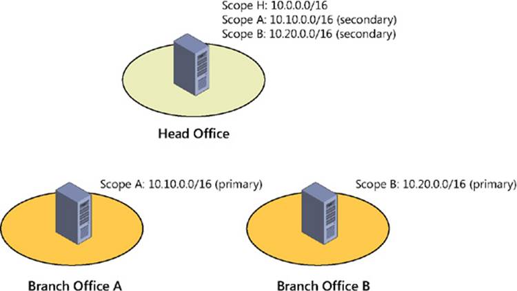
FIGURE 6-1 Implement DHCP failover in hot-standby mode in a hub-and-spoke site scenario.
![]() Quick check
Quick check
![]() Which DHCP failover mode would you implement for an organization whose sites form a hub-and-spoke topology?
Which DHCP failover mode would you implement for an organization whose sites form a hub-and-spoke topology?
Quick check answer
![]() Hot-standby mode
Hot-standby mode
Note: DHCP packets over multiple subnets
Routers usually block DHCP packets from being forwarded from one subnet to another because DHCP packets are broadcast traffic. If an organization’s network consists of multiple subnets, using DHCP for dynamic address assignment requires one of the following:
![]() Deploying a DHCP server on each subnet of your network
Deploying a DHCP server on each subnet of your network
![]() Enabling forwarding of DHCP traffic on your routers by configuring them as DHCP relay agents
Enabling forwarding of DHCP traffic on your routers by configuring them as DHCP relay agents
In general, the first approach is recommended because it provides a greater degree of fault tolerance. For more information, see http://support.microsoft.com/kb/120932.
Implementing DHCP failover
To enable DHCP failover, begin by installing two DHCP servers running Windows Server 2012 or Windows Server 2012 R2, designating one of them as the primary server and the other as the secondary server. If the DHCP servers are domain members, they must be authorized in Active Directory. However, you can also implement DHCP failover on stand-alone DHCP servers in a workgroup.
After deploying your two DHCP servers, create and configure scopes on the primary DHCP server for the DHCP clients in your environment. Then perform the following steps:
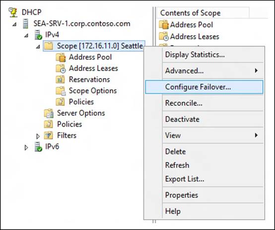
1. Open the DHCP console and add the primary server. Then right-click a scope and select Configure Failover:
2. In the Configure Failover Wizard, select an available scope.
3. Add the partner server that will be used as the secondary server for the host server (the primary server).
4. Configure the new failover relationship for either load-balance mode (shown in Figure 6-2) or standby mode (shown in Figure 6-3). Adjust the mode settings to meet the needs of your environment.
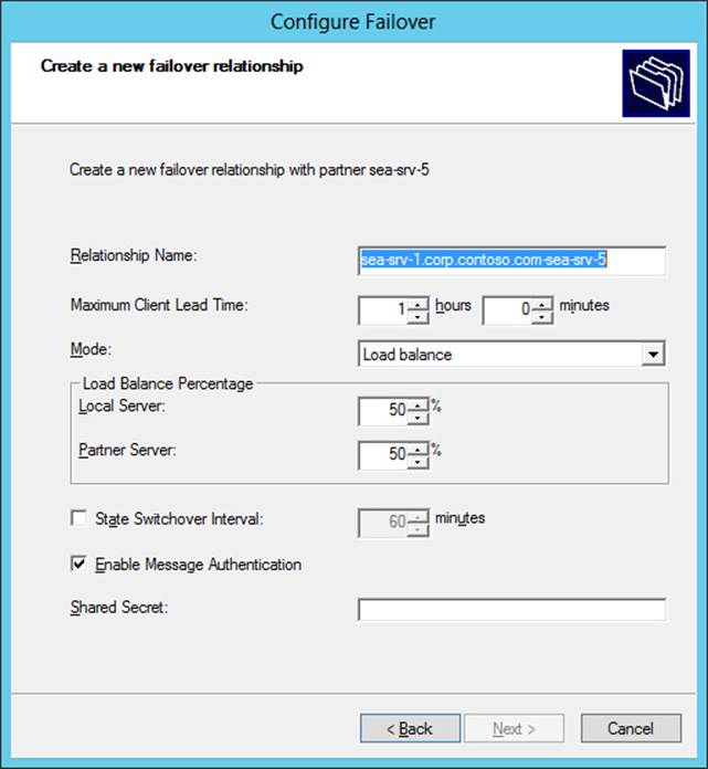
FIGURE 6-2 Create a new DHCP server failover relationship using load-balance mode.
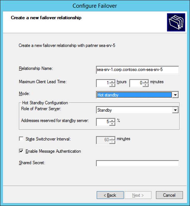
FIGURE 6-3 Create a new DHCP server failover relationship using hot-standby mode.
5. Complete the wizard and make sure the progress dialog indicates success for all operations.
Completing the preceding steps should accomplish these actions:
1. Add scopes on the partner server.
2. Disable scopes on the partner server.
3. Create a failover configuration on the partner server.
4. Create a failover configuration on the host server.
5. Activate the scopes on the partner server.
Note: DHCP failover and Windows PowerShell
You can also use Windows PowerShell to implement DHCP failover. The practice exercises in this chapter give you an opportunity to do this.
Managing DHCP failover
After DHCP failover is enabled and configured, you can manage your DHCP failover solution using the DHCP console. Examples of management tasks you can perform for DHCP server failover include the following:
![]() Configuring a new failover relationship by right-clicking either another scope or the IPv4 node for the server and selecting Configure Failover
Configuring a new failover relationship by right-clicking either another scope or the IPv4 node for the server and selecting Configure Failover
![]() Removing a failover relationship from a scope that has previously been configured for failover by right-clicking the scope and selecting Deconfigure Failover
Removing a failover relationship from a scope that has previously been configured for failover by right-clicking the scope and selecting Deconfigure Failover
![]() Viewing the failover configuration for a scope by right-clicking the scope, selecting Properties, and selecting the Failover tab
Viewing the failover configuration for a scope by right-clicking the scope, selecting Properties, and selecting the Failover tab
![]() Viewing the failover status, failover mode, and partner server by right-clicking the IPv4 node for a server, selecting Properties, and selecting the Failover tab
Viewing the failover status, failover mode, and partner server by right-clicking the IPv4 node for a server, selecting Properties, and selecting the Failover tab
![]() Editing the failover relationship for the server by right-clicking the IPv4 node for a server, selecting Properties, selecting the Failover tab, and clicking Edit to open the View/Edit Failover Relationship properties (as shown in Figure 6-4)
Editing the failover relationship for the server by right-clicking the IPv4 node for a server, selecting Properties, selecting the Failover tab, and clicking Edit to open the View/Edit Failover Relationship properties (as shown in Figure 6-4)
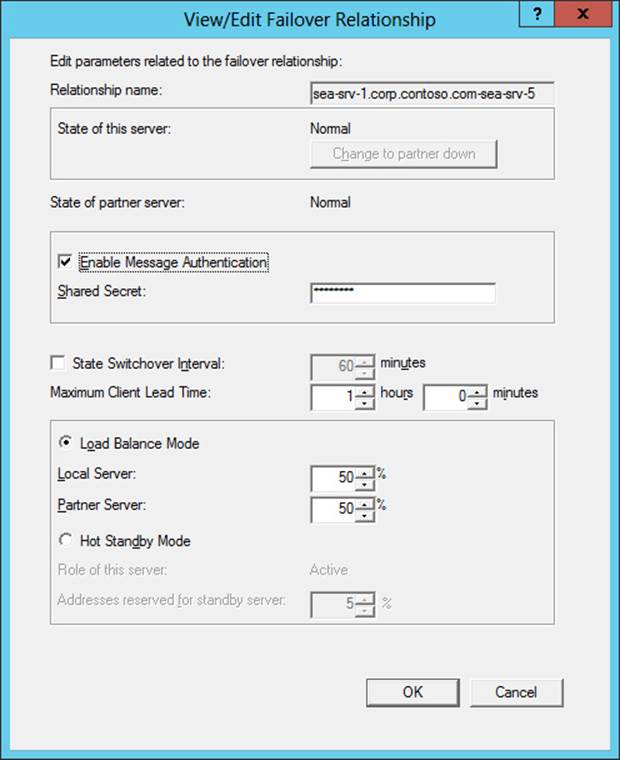
FIGURE 6-4 Modify the properties of a DHCP server failover relationship.
![]() Forcing the replication of a scope in a failover relationship to the partner server for that relationship by right-clicking the scope and selecting Replicate Scope
Forcing the replication of a scope in a failover relationship to the partner server for that relationship by right-clicking the scope and selecting Replicate Scope
![]() Forcing the replication of all scopes in a failover relationship to the partner server for that relationship by right-clicking the scope and selecting Replicate Relationship
Forcing the replication of all scopes in a failover relationship to the partner server for that relationship by right-clicking the scope and selecting Replicate Relationship
![]() Forcing the replication of all scopes in all failover relationships to the partner servers for those relationships by right-clicking the IPv4 node for the server and selecting Replicate Failover Scopes
Forcing the replication of all scopes in all failover relationships to the partner servers for those relationships by right-clicking the IPv4 node for the server and selecting Replicate Failover Scopes
Note: Forcing replication
Replication of DHCP database information should occur automatically when DHCP servers have been configured for failover. Manually forcing replication generally needs to be performed only when you are troubleshooting replication issues.
Lesson summary
![]() DHCP availability solutions for previous Windows Server versions each have advantages and disadvantages.
DHCP availability solutions for previous Windows Server versions each have advantages and disadvantages.
![]() DHCP failover is a new approach to ensuring DHCP server availability that was introduced in Windows Server 2012.
DHCP failover is a new approach to ensuring DHCP server availability that was introduced in Windows Server 2012.
![]() DHCP failover is supported only for IPv4 scopes.
DHCP failover is supported only for IPv4 scopes.
![]() DHCP failover can be implemented in two different configurations: load-balance mode or hot-standby mode.
DHCP failover can be implemented in two different configurations: load-balance mode or hot-standby mode.
![]() A typical scenario in which you might implement load-balance mode is when you want to have two DHCP servers at the same physical site.
A typical scenario in which you might implement load-balance mode is when you want to have two DHCP servers at the same physical site.
![]() A typical scenario in which you might implement hot-standby mode is in organizations that have a central hub site connected via WAN links to multiple remote branch-office sites.
A typical scenario in which you might implement hot-standby mode is in organizations that have a central hub site connected via WAN links to multiple remote branch-office sites.
![]() You can implement DHCP failover by using the DHCP console or Windows PowerShell.
You can implement DHCP failover by using the DHCP console or Windows PowerShell.
![]() Each DHCP failover relationship can include only two DHCP servers, but it can apply to multiple scopes on the servers.
Each DHCP failover relationship can include only two DHCP servers, but it can apply to multiple scopes on the servers.
Lesson review
Answer the following questions to test your knowledge of the information in this lesson. You can find the answers to these questions and explanations of why each answer choice is correct or incorrect in the “Answers” section at the end of this chapter.
1. Which approach to ensuring DHCP availability involves dividing up the IP address pool of a scope between two DHCP servers, typically using the ratio 80:20?
A. Server cluster
B. Split scope
C. Standby server
D. DHCP failover
2. Which of the following is true concerning DHCP failover in Windows Server 2012 and Windows Server 2012 R2? (Choose all that apply.)
A. DHCP failover only supports using a maximum of two DHCP servers.
B. DHCP failover is supported for both IPv4 and IPv6 scopes and subnets.
C. DHCP failover can be implemented in two ways: load-balance mode or hot-standby mode.
D. DHCP failover requires that the DHCP servers be domain members and authorized in Active Directory.
3. Which of the following scenarios might be appropriate for implementing DHCP failover in hot-standby mode? (Choose all that apply.)
A. Your organization has a hub-and-spoke site topology.
B. You want to use the DHCP server in your data center as a standby in case a DHCP server at one of your remote branch offices goes offline.
C. Your organization has a hub-and-spoke site topology, but you have a limited budget for deploying additional servers as standbys for existing servers in your environment.
D. Your organization has only one physical site.
Lesson 2: Implementing DNSSEC
DNS provides a user-friendly way of naming hosts and services on a TCP/IP network. DNS servers perform name resolution to convert DNS names into IP addresses so that DNS clients can access network services. DNS servers thus play a critical role in enabling users and applications to locate hosts and services on the network or on the Internet. However, no authentication or integrity checking is done when name resolution is being performed using traditional DNS. As a result, communication between DNS clients and servers is inherently insecure. By spoofing DNS traffic or otherwise poisoning the DNS cache on clients, an attacker could hijack network communications and redirect users and applications to malicious sites and services.
To help organizations address these problems, Windows Server 2012 and Windows Server 2012 R2 include enhanced support for DNS Security Extensions (DNSSEC), a suite of extensions that add security to the DNS protocol by enabling DNS servers to validate DNS responses. In a practical sense, this enables users to be confident that the site they are accessing on their corporate intranet is in fact the site they believe it to be and not some malicious site masquerading as a legitimate site. This lesson helps you understand the benefits of DNSSEC, how it works, and how to implement it in an Active Directory environment based on Windows Server 2012 or Windows Server 2012 R2.
After this lesson, you will be able to:
![]() Explain what types of security DNSSEC provides and describe its benefits for organizations.
Explain what types of security DNSSEC provides and describe its benefits for organizations.
![]() Compare and contrast DNSSEC functionality in Windows Server 2012 and Windows Server 2012 R2 with that in previous Windows Server versions.
Compare and contrast DNSSEC functionality in Windows Server 2012 and Windows Server 2012 R2 with that in previous Windows Server versions.
![]() Describe how DNSSEC works as part of the name-resolution process.
Describe how DNSSEC works as part of the name-resolution process.
![]() Explain DNSSEC concepts such as zone signing, key master, and trust anchors.
Explain DNSSEC concepts such as zone signing, key master, and trust anchors.
![]() List the different kinds of DNSSEC resource records and describe what they are used for.
List the different kinds of DNSSEC resource records and describe what they are used for.
![]() Deploy DNSSEC in a Windows Server 2012 or Windows Server 2012 R2 Active Directory environment using the DNS Manager MMC console.
Deploy DNSSEC in a Windows Server 2012 or Windows Server 2012 R2 Active Directory environment using the DNS Manager MMC console.
Estimated lesson time: 30 minutes
Benefits of DNSSEC
DNS is used for locating resources on a TCP/IP network and the Internet. For example, when a user types www.bing.com into the address bar of Internet Explorer, the DNS client on the user’s computer sends a name query request to a DNS server. The DNS server then either responds with the IP address for the site being accessed (Bing) or forwards the query to another DNS server for consideration. When the client has the site’s IP address, it can access the site to download content.
But this question arises: How can the user or application be confident that the site being accessed is genuine and not some fake site masquerading as the real one? To a certain extent, the Secure Sockets Layer (SSL) protocol already does this. SSL is used whenever the user or application accesses a resource using Secure HTTP (HTTPS). SSL does this by authenticating the site being accessed and encrypting the data returned over the network. However, SSL is of no use if the DNS server being queried returns a spoofed IP address instead of the real one. This could be accomplished, for example, if a malicious DNS server intercepted name-resolution traffic and inserted a spoofed response to a query from a DNS client or a recursive DNS server. Not only could such an attack hijack a particular DNS session, it also would also poison the local DNS cache on the client server, recursive server, or both, which could lead to further erroneous responses to name-resolution requests until the cache data expired.
To address these issues, the Internet Engineering Task Force (IETF) developed DNSSEC to add a layer of security to the inherently insecure DNS protocol. Specifically, DNSSEC helps prove two things:
![]() The information the client is accessing is coming from the correct source. In other words, it confirms the authority of the originator of the data that a DNS server returns.
The information the client is accessing is coming from the correct source. In other words, it confirms the authority of the originator of the data that a DNS server returns.
![]() The information you receive is the same as the information that was sent. In other words, it confirms the integrity of the data that a DNS server returns.
The information you receive is the same as the information that was sent. In other words, it confirms the integrity of the data that a DNS server returns.
DNSSEC also provides authenticated denial of existence when the information the client is trying to access does not exist. In other words, it provides proof that the site being requested really doesn’t exist.
What DNSSEC does not provide is confidentiality of the data that a DNS server returns. In other words, it does not guarantee that the data hasn’t been intercepted and examined while en route to the client. DNSSEC also does not provide any protection against a distributed denial-of-service (DDoS) attack against an organization’s DNS infrastructure. So although DNSSEC provides two of the requirements of the information security CIA triad (Confidentiality, Integrity, and Availability), it is not in itself a complete solution to the problem of protecting an organization’s DNS infrastructure and traffic.
More Info: How DNS works
For a detailed look at how the DNS name-resolution process works, see “How DNS Works” at http://technet.microsoft.com/en-us/library/dd197446(v=WS.10).aspx.
Real World: Why you should deploy DNSSEC
There are several reasons why organizations today need to consider deploying DNSSEC in their Windows Server–based environments:
![]() DNSSEC provides protection from DNS cache poisoning and other types of attacks that can compromise an organization’s security.
DNSSEC provides protection from DNS cache poisoning and other types of attacks that can compromise an organization’s security.
![]() DNSSEC provides an additional layer of security for enterprises that have private clouds deployed or use extranets for business communications.
DNSSEC provides an additional layer of security for enterprises that have private clouds deployed or use extranets for business communications.
![]() Revision 3 of National Institute of Standards and Technology (NIST) Special Publication (SP) 800-53 mandates the requirement of DNSSEC for internal DNS zone signing on U.S. federal government information systems.
Revision 3 of National Institute of Standards and Technology (NIST) Special Publication (SP) 800-53 mandates the requirement of DNSSEC for internal DNS zone signing on U.S. federal government information systems.
In addition, DNSSEC is likely to become a regulatory requirement for some industries, such as finance and banking.
DNSSEC in previous Windows Server versions
Basic support for DNSSEC was introduced in Windows Server 2003 to enable DNS servers to act as secondary DNS servers for existing DNSSEC-compliant secure zones. Windows Server 2003 DNS servers, however, were not capable of signing zones and resource records or validating theSignature (SIG) resource records. In addition, all DNSSEC configuration had to be performed by editing the registry on DNS servers.
Support for DNSSEC was enhanced in Windows Server 2008 R2 but was limited because it was intended as a solution only for file-backed, static zones and not for dynamic Active Directory–integrated zones. The DNS server command-line management tool (Dnscmd.exe) could be used to perform offline key generation and zone-signing capability through a signing tool. Windows PowerShell scripts were later released through the TechNet Script Center for performing DNSSEC administration tasks such as signing zones and for adding, rolling over, and verifying trust anchors. However, the DNS client in Windows 7 and Windows Server 2008 R2 is DNSSEC-aware but nonvalidating. In other words, the DNS client can examine a response received from a DNS server to determine whether the response has been validated by the DNS server, but the client cannot itself validate the response it receives from the DNS server. This means that you must use some other method, such as Internet Protocol security (IPsec), to secure the last mile between the client and its local DNS server, even when DNSSEC has been configured on DNS servers running Windows Server 2008 R2.
Windows Server 2012 and Windows Server 2012 R2 include full DNSSEC support for Active Directory–integrated DNS scenarios, including DNS dynamic updates in DNSSEC signed zones, automated trust-anchor distribution through Active Directory, automated trust-anchor rollover support per RFC 5011, and validation of records signed with updated DNSSEC standards (NSEC3, RSA/SHA-2). An updated user interface with deployment and management wizards and full Windows PowerShell support for configuring and managing DNSSEC are also included. However, the DNS client in Windows 8, Windows 8.1, Windows Server 2012, and Windows Server 2012 R2 is still DNSSEC-aware but nonvalidating, which means you should still use IPsec to secure the network connecting the client to its local DNS server.
How DNSSEC works
DNSSEC works by combining public key infrastructure (PKI) cryptography with DNS to use digital signatures and cryptographic keys to sign DNS zones and validate that DNS responses are authentic. Figure 6-5 shows the steps involved in the name-resolution process when DNSSEC has been implemented in a Windows Server–based network. The basic steps involved are as follows:
1. A client such as a Windows 8 computer issues a DNS query to its local DNS server.
2. The client’s local DNS server has DNSSEC enabled but is not authoritative for the zone being queried, so it issues a recursive query to the authoritative server for the zone to request an authoritative response.
3. The authoritative server has DNSSEC enabled and is the authoritative server for the zone being queried. This means that the zone has been digitally signed on this server. When the authoritative server receives the recursive query, it returns an authoritative response to the client’s local server. This response includes one or more DNSSEC resource records, which can include the following types:
![]() Resource Record Signature (RRSIG) These resource records contain digital signatures for all records in a zone.
Resource Record Signature (RRSIG) These resource records contain digital signatures for all records in a zone.
![]() DNS Public Key (DNSKEY) These resource records contain the public keys for a particular zone.
DNS Public Key (DNSKEY) These resource records contain the public keys for a particular zone.
![]() Delegation Signer (DS) These resource records indicate the public key for a child zone.
Delegation Signer (DS) These resource records indicate the public key for a child zone.
![]() Next Secure (NSEC or NSEC3) These resource records allow the validation of a negative response.
Next Secure (NSEC or NSEC3) These resource records allow the validation of a negative response.
4. The local server uses the public key of the signed zone on the authoritative server to validate the response it received from the authoritative server.
5. The local server returns the requested response to the client that issued the query. The client can now access the network resource represented by the name for which it was querying.
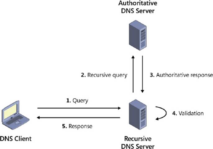
FIGURE 6-5 Review how DNSSEC works.
![]() Quick check
Quick check
![]() When DNSSEC is implemented on a Windows Server–based network, where is validation performed for the response to a client’s DNS query?
When DNSSEC is implemented on a Windows Server–based network, where is validation performed for the response to a client’s DNS query?
Quick check answer
![]() On the client’s local DNS server, not on the client itself
On the client’s local DNS server, not on the client itself
Deploying DNSSEC
Deploying DNSSEC using Windows Server 2012 or Windows Server 2012 R2 into an existing Active Directory environment involves performing the following steps:
1. Begin by introducing Windows Server 2012 or Windows Server 2012 R2 domain controllers into your environment. These domain controllers should also have the DNS Server role installed and be configured to use Active Directory–integrated zones. Note that the schema must be updated to Windows Server 2012 level or higher to support the DNSSEC extensions.
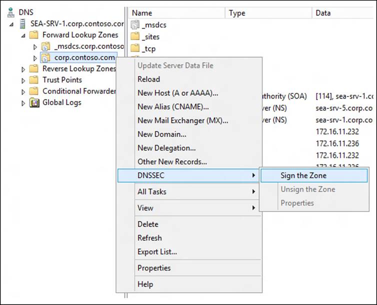
2. DNSSEC is implemented by signing zones on your DNS servers. After deciding which DNS zone to implement DNSSEC on, sign the zone by opening the DNS Manager console, selecting the DNS server, right-clicking the zone, selecting DNSSEC, and then selecting Sign The Zone:
3. Follow the prompts of the Zone Signing Wizard to complete the process of signing the zone. The simplest approach is to use the default settings to sign the zone:
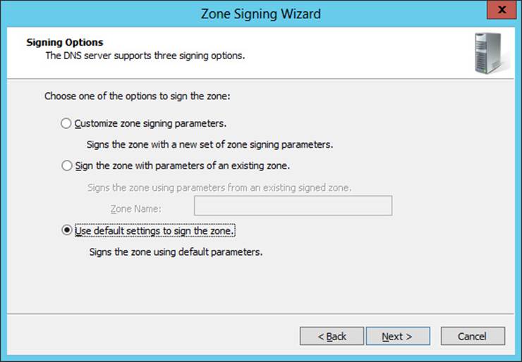
For example, selecting this option when signing the corp.contoso.com zone on your first Windows Server 2012 R2 domain controller DC-1.corp.contoso.com would have the following results:
![]() The domain controller becomes the key master for the corp.contoso.com zone. The key master is the DNS server that generates and manages signing keys for a zone that is protected with DNSSEC.
The domain controller becomes the key master for the corp.contoso.com zone. The key master is the DNS server that generates and manages signing keys for a zone that is protected with DNSSEC.
![]() A key signing key (KSK) with a length of 2048 bits is generated using the RSA/SHA-256 cryptographic algorithm. The KSK is an authentication key that signs all of the DNSKEY records at the root of the zone, and it is part of the chain of trust. By default, the KSK has a rollover frequency of 755 days and any DNSKEY records signed using the key have a signature validity of 168 hours. Key rollover and signature refresh are enabled by default on Windows Server 2012 R2 DNS servers.
A key signing key (KSK) with a length of 2048 bits is generated using the RSA/SHA-256 cryptographic algorithm. The KSK is an authentication key that signs all of the DNSKEY records at the root of the zone, and it is part of the chain of trust. By default, the KSK has a rollover frequency of 755 days and any DNSKEY records signed using the key have a signature validity of 168 hours. Key rollover and signature refresh are enabled by default on Windows Server 2012 R2 DNS servers.
![]() A zone signing key (ZSK) with a length of 1024 bits is generated using the RSA/SHA-256 algorithm. The ZSK is used to sign zone data, such as the SOA, NS, and A resource records found in a typical zone. By default, the ZSK has a rollover frequency of 90 days and any zone resource records signed using the key have a signature validity of 240 hours. Key rollover and signature refresh are enabled by default on Windows Server 2012 R2 DNS servers.
A zone signing key (ZSK) with a length of 1024 bits is generated using the RSA/SHA-256 algorithm. The ZSK is used to sign zone data, such as the SOA, NS, and A resource records found in a typical zone. By default, the ZSK has a rollover frequency of 90 days and any zone resource records signed using the key have a signature validity of 240 hours. Key rollover and signature refresh are enabled by default on Windows Server 2012 R2 DNS servers.
![]() NSEC3 is used by default for providing authenticated denial of existence. The NSEC3 hash algorithm used is RSA/SHA-1 with 50 iterations and a salt length of 8.
NSEC3 is used by default for providing authenticated denial of existence. The NSEC3 hash algorithm used is RSA/SHA-1 with 50 iterations and a salt length of 8.
Trust anchors are not distributed. A trust anchor is a preconfigured public key associated with a specific zone. The trust anchor enables DNS servers to validate DNSKEY resource records for the corresponding zone and establish a chain of trust to child zones, if any exist. Validating DNS servers must be configured with one or more trust anchors to perform DNSSEC validation. If the DNS server is running on a domain controller, trust anchors are stored in the forest directory partition in Active Directory.
1. If the zone you signed is an Active Directory–integrated zone, private zone signing keys now replicate automatically to all domain controllers hosting the zone through Active Directory replication. Each zone owner signs its own copy of the zone when it receives the key as long as the zone owner is a domain controller running Windows Server 2012 or Windows Server 2012 R2.
Most of the key-management process is automated for DNSSEC in Windows Server 2012 and Windows Server 2012 R2. After the key rollover frequency has been configured for a zone using the Zone Signing Wizard, the key master automatically generates new keys and replicates through Active Directory. The zone owner rolls over keys and re-signs the zone, and secure delegations from the parent are also automatically updated within the same forest.
2. At this point, the zone has been signed and contains the necessary RRSIG, DNSKEY, DS, and NSEC3 resource records to support DNSSEC validation:
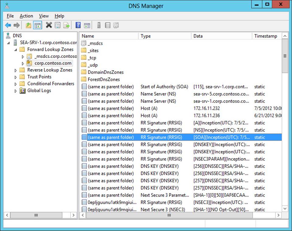
3. When zone data is updated by a client sending a DNS dynamic update to an authoritative DNS server, that DNS server updates its own copy of the zone and generates the required signatures. The unsigned update is then securely replicated to all other authoritative servers, and each DNS server adds the update to its copy of the zone and generates the required signatures.
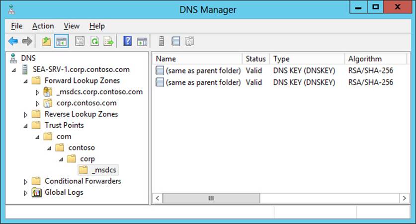
4. Trust anchors must then be distributed to the DNS servers in your environment to enable the DNSSEC validation process to be performed by nonauthoritative (recursive or caching) DNS servers. If the DNS servers are running on domain controllers, trust anchors are stored in the forest directory partition in Active Directory and are replicated to all domain controllers in the forest. On stand-alone DNS servers, trust anchors are stored in a file named TrustAnchors.dns and can be manually imported to these servers using the DNS Manager console or Windows PowerShell.
For example, the stand-alone DNS server running Windows Server 2012 R2 shown next displays its configured trust anchors in the DNS Manager console tree in the Trust Points container. Note that two DNSKEY trust points are displayed: one for the active key and one for the standby key.
5. Trust Anchor updates are then automatically replicated through Active Directory to all servers in the forest, and automated Trust Anchor rollover is used to keep trust anchors up to date.
6. The final step in deploying DNSSEC is to ensure security between the nonvalidating DNS clients (which can be computers running Windows 7, Windows 8, Windows Server 2008 R2, Windows Server 2012, or Windows Server 2012 R2) and their local DNS servers. The recommended way to do this is to use IPsec to protect the last mile between the client and its local DNS server. The DNS clients must also be configured to check that responses have been validated by their local DNS server, and you do this by configuring the Name Resolution Policy Table (NRPT) on the clients. The NRPT is a table that contains rules you can configure to specify DNS settings or special behavior for names or namespaces. You can configure the NRPT by using either Group Policy or Windows PowerShell.
Lesson summary
![]() DNSSEC is a suite of extensions that add security to the DNS protocol by enabling DNS servers to validate DNS responses.
DNSSEC is a suite of extensions that add security to the DNS protocol by enabling DNS servers to validate DNS responses.
![]() DNSSEC confirms the authority of the originator and the integrity of the data being returned.
DNSSEC confirms the authority of the originator and the integrity of the data being returned.
![]() DNSSEC provides authenticated denial of existence when the information the client is trying to access does not exist. In other words, it provides proof that the site being requested really doesn’t exist.
DNSSEC provides authenticated denial of existence when the information the client is trying to access does not exist. In other words, it provides proof that the site being requested really doesn’t exist.
![]() DNSSEC does not provide confidentiality for the data a DNS server returns.
DNSSEC does not provide confidentiality for the data a DNS server returns.
![]() DNSSEC works by combining public key infrastructure (PKI) cryptography with DNS to use digital signatures and cryptographic keys to sign DNZ zones and validate that DNS responses are authentic.
DNSSEC works by combining public key infrastructure (PKI) cryptography with DNS to use digital signatures and cryptographic keys to sign DNZ zones and validate that DNS responses are authentic.
![]() DNSSEC is implemented by signing zones on your DNS servers. Signing a zone adds new resource records of types RRSIG, DNSKEY, DS, and NSEC (or NSEC3) into the zone.
DNSSEC is implemented by signing zones on your DNS servers. Signing a zone adds new resource records of types RRSIG, DNSKEY, DS, and NSEC (or NSEC3) into the zone.
![]() Most of the key-management process is automated for DNSSEC in Windows Server 2012 and Windows Server 2012 R2. However, trust anchors must be manually distributed to stand-alone DNS servers.
Most of the key-management process is automated for DNSSEC in Windows Server 2012 and Windows Server 2012 R2. However, trust anchors must be manually distributed to stand-alone DNS servers.
![]() The DNS client in Windows 7, Windows 8, Windows Server 2008, Windows Server 2008 R2, Windows Server 2012, and Windows Server 2012 R2 is DNSSEC-aware but nonvalidating. This means that you should use IPsec to secure the network connecting the client to its local DNS server.
The DNS client in Windows 7, Windows 8, Windows Server 2008, Windows Server 2008 R2, Windows Server 2012, and Windows Server 2012 R2 is DNSSEC-aware but nonvalidating. This means that you should use IPsec to secure the network connecting the client to its local DNS server.
Lesson review
Answer the following questions to test your knowledge of the information in this lesson. You can find the answers to these questions and explanations of why each answer choice is correct or incorrect in the “Answers” section at the end of this chapter.
1. Which of the following is not a correct explanation of a DNSSEC term or concept?
A. DNSKEY resource records contain the public keys for a particular zone.
B. Only zones that are authoritative can be signed.
C. The key signing key (KSK) is used to sign all of the DNSKEY records at the root of the zone.
D. When zone data is updated by a client sending a DNS dynamic update to an authoritative DNS server, the entire zone must be re-signed.
2. In a Windows Server–based DNS infrastructure in which DNSSEC has been implemented, where is the validation of the response to a query performed?
A. On an authoritative DNS server in the forest root domain
B. On an authoritative DNS server in a child or tree domain
C. On a recursive DNS server that is not authoritative for the zone being queried
D. On the client computer issuing the name query
3. When you want to implement DNSSEC in an Active Directory environment in which all DNS servers are domain controllers and use only Active Directory–integrated zones, which of the following steps in the DNSSEC deployment process is not correct?
A. Begin by introducing Windows Server 2012 or Windows Server 2012 R2 domain controllers into your environment.
B. After deciding which DNS zone to implement DNSSEC on, sign the zone.
C. Use Robocopy.exe to replicate the private zone signing keys to all domain controllers hosting the zone.
D. Use IPsec to protect the last mile between the nonvalidating DNS client and its local DNS server.
Lesson 3: Managing networking using Windows PowerShell
Managing network settings and services is a core task for administrators of Windows Server–based networks. Examples of network configuration tasks include configuring interfaces, IP addresses, default gateways, routes, and metrics; configuring ISATAP and Teredo for IPv4/IPv6 interoperability; and similar tasks. Examples of network service tasks include configuring DHCP scopes, options, and reservations; creating different types of DNS zones; configuring DNS root hints and forwarders; creating resource records; and similar tasks.
In earlier versions of Windows Server, such tasks usually had to be performed using a combination of GUI tools and various command-line utilities. But with the significantly increased Windows PowerShell capabilities built into Windows Server 2012 and Windows Server 2012 R2, you can perform most network-administration tasks from the Windows PowerShell command line or by running Windows PowerShell scripts. This lesson demonstrates how to identify network components that have Windows PowerShell support and how to perform common network-administration tasks and troubleshooting using Windows PowerShell.
After this lesson, you will be able to:
![]() Identify possible Windows PowerShell cmdlets that you can use for performing specific network-management tasks.
Identify possible Windows PowerShell cmdlets that you can use for performing specific network-management tasks.
![]() Use the Show-Command cmdlet to learn the syntax of other cmdlets.
Use the Show-Command cmdlet to learn the syntax of other cmdlets.
![]() Configure TCP/IP address settings using Windows PowerShell.
Configure TCP/IP address settings using Windows PowerShell.
![]() Manage different aspects of network adapters using Windows PowerShell.
Manage different aspects of network adapters using Windows PowerShell.
![]() Manage DHCP servers using Windows PowerShell.
Manage DHCP servers using Windows PowerShell.
![]() Manage DNS servers using Windows PowerShell.
Manage DNS servers using Windows PowerShell.
![]() Troubleshoot networking problems using Windows PowerShell.
Troubleshoot networking problems using Windows PowerShell.
Estimated lesson time: 40 minutes
Identifying networking cmdlets
In Windows Server 2012 and Windows Server 2012 R2, there are hundreds of Windows PowerShell cmdlets that you can use to view, configure, and monitor different networking components and services in the platform. The tasks you can perform using these cmdlets range from the common (such as configuring static IP addresses or DHCP reservations for servers) to the more specialized (such as configuring quality-of-service parameters) to the settings related to virtual environments (such as configuring the Hyper-V extensible switch). There is obviously too much to learn here in a single lesson or even a single book, and many administrators might perform some tasks only occasionally, or even not at all. So let’s begin with a more practical approach to the problem of administering a Windows Server 2012 or Windows Server 2012 R2 networking environment using Windows PowerShell by asking a simple question: How can you find the right cmdlet (if there is a cmdlet) to perform a particular networking task?
Using Get-Command
You could start by using the Get-Command cmdlet to search for all Windows PowerShell cmdlets and functions that have the string “net” in their names. This generates a lot of output, however, as shown here:
PS C:\> Get-Command *net*
CommandType Name ModuleName
----------- ---- ----------
Function Add-NetIPHttpsCertBinding NetworkTransition
Function Add-NetLbfoTeamMember NetLbfo
Function Add-NetLbfoTeamNic NetLbfo
Function Add-NetSwitchTeamMember NetSwitchTeam
Function Copy-NetFirewallRule NetSecurity
Function Copy-NetIPsecMainModeCryptoSet NetSecurity
Function Copy-NetIPsecMainModeRule NetSecurity
Function Copy-NetIPsecPhase1AuthSet NetSecurity
Function Copy-NetIPsecPhase2AuthSet NetSecurity
Function Copy-NetIPsecQuickModeCryptoSet NetSecurity
Function Copy-NetIPsecRule NetSecurity
Function Disable-NetAdapter NetAdapter
Function Disable-NetAdapterBinding NetAdapter
Function Disable-NetAdapterChecksumOffload NetAdapter
Function Disable-NetAdapterEncapsulatedPacketTaskOffload NetAdapter
Function Disable-NetAdapterIPsecOffload NetAdapter
...
From the preceding output, you can see there are several Windows PowerShell modules that perform network-related actions. To see this more clearly, the following commands take the preceding output, sort it by module name, and remove duplicates:
PS C:\> Get-Command *net* | Sort-Object ModuleName | Format-Table ModuleName `
-HideTableHeaders | Out-String | Out-File c:\data\test.txt
PS C:\> Get-Content C:\data\test.txt | Get-Unique
ActiveDirectory
BranchCache
DnsServer
MsDtc
NetAdapter
NetConnection
NetLbfo
NetQos
NetSecurity
NetSwitchTeam
NetTCPIP
NetworkTransition
NFS
SmbShare
To investigate the NetTCPIP module further, you can use the –Module parameter of Get-Command to list all cmdlets and functions contained in this module:
PS C:\> Get-Command -Module NetTCPIP | Sort-Object Name | Format-Table Name
Name
----
Get-NetIPAddress
Get-NetIPConfiguration
Get-NetIPInterface
Get-NetIPv4Protocol
Get-NetIPv6Protocol
Get-NetNeighbor
Get-NetOffloadGlobalSetting
Get-NetPrefixPolicy
Get-NetRoute
Get-NetTCPConnection
Get-NetTCPSetting
Get-NetTransportFilter
Get-NetUDPEndpoint
Get-NetUDPSetting
New-NetIPAddress
New-NetNeighbor
New-NetRoute
New-NetTransportFilter
Remove-NetIPAddress
Remove-NetNeighbor
Remove-NetRoute
Remove-NetTransportFilter
Set-NetIPAddress
Set-NetIPInterface
Set-NetIPv4Protocol
Set-NetIPv6Protocol
Set-NetNeighbor
Set-NetOffloadGlobalSetting
Set-NetRoute
Set-NetTCPSetting
Set-NetUDPSetting
Using Show-Command
At this point, you can begin using Get-Help to learn about the syntax of NetTCPIP cmdlets in which you’re interested and to see some examples of their usage. Unfortunately for administrators who are not very familiar with Windows PowerShell, the syntax displayed when you use Get-Help with a cmdlet can appear daunting. For example, consider a scenario in which you have a web server running Windows Server 2012 or Windows Server 2012 R2 and you want to add a second IP address to a network adapter on the server.
You might guess from the output of Get-Command –Module NetTCPIP shown previously that New-NetIPAddress is the cmdlet you use to perform this task, and you would be correct. But to the Windows PowerShell beginner, the syntax from Get-Help New-NetIPAddress might look quite confusing:
Parameter Set: ByInterfaceAlias
New-NetIPAddress -InterfaceAlias <String> [-AddressFamily <AddressFamily> ] [-AsJob]
[-CimSession <CimSession[]> ] [-DefaultGateway <String> ] [-IPv4Address <String> ]
[-IPv6Address <String> ] [-PassThru] [-PreferredLifetime <TimeSpan> ]
[-PrefixLength <Byte> ] [-PrefixOrigin <PrefixOrigin> ] [-SkipAsSource <Boolean> ]
[-Store <Store> ] [-SuffixOrigin <SuffixOrigin> ] [-ThrottleLimit <Int32> ]
[-Type <Type> ] [-ValidLifetime <TimeSpan> ] [-Confirm] [-WhatIf] [ <CommonParameters>]
Parameter Set: ByIfIndexOrIfAlias
New-NetIPAddress [-AddressFamily <AddressFamily> ] [-AsJob]
[-CimSession <CimSession[]> ] [-DefaultGateway <String> ] [-InterfaceAlias <String> ]
[-InterfaceIndex <UInt32> ] [-IPv4Address <String> ] [-IPv6Address <String> ]
[-PassThru] [-PreferredLifetime <TimeSpan> ] [-PrefixLength <Byte> ]
[-PrefixOrigin <PrefixOrigin> ] [-SkipAsSource <Boolean> ] [-Store <Store> ]
[-SuffixOrigin <SuffixOrigin> ] [-ThrottleLimit <Int32> ] [-Type <Type> ]
[-ValidLifetime <TimeSpan> ] [-Confirm] [-WhatIf] [ <CommonParameters>]
Fortunately, the new Show-Command cmdlet introduced in Windows Server 2012 can help make the syntax of Windows PowerShell cmdlets easier to understand and use. Start by typing the following command:
PS C:\> Show-Command New-NetIPAddress
Note: Using Show-Command on Server Core
To use the Show-Command cmdlet on a Windows Server Core installation, you must first install the Windows PowerShell ISE feature on the server.
When you run the preceding command, the properties page shown in Figure 6-6 opens to show you the different parameters you can use with the New-NetIPAddress cmdlet. Parameters such as InterfaceAlias and IPAddress that are marked with an asterisk are mandatory; those not marked this way are optional.
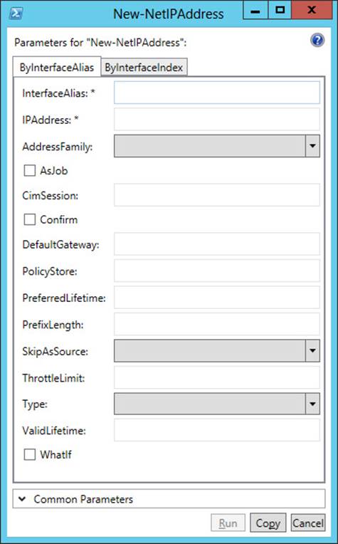
FIGURE 6-6 The Show-Command properties page for the New-NetIPAddress cmdlet shows you the parameters you can use.
To add a new IP address, you first need to know the alias or index of the network interface to which you want to add the address. To find the interfaces on the system, you could use Get-Command *interface* to find all cmdlets that include “interface” in their name. Of the eight cmdlets displayed when you run this command, the cmdlet Get-NetIpInterface is the one you are looking for, and running this cmdlet displays a list of all interfaces on the server:
PS C:\> Get-NetIPInterface
ifIndex InterfaceAlias AddressFamily NlMtu(Bytes) InterfaceMetric Dhcp
------- -------------- ------------- ------------ --------------- ----
12 Ethernet IPv6 1500 5 Disabled
14 Teredo Tunneling Pseudo... IPv6 1280 50 Disabled
13 isatap.{4B8DC8AE-DE20-4... IPv6 1280 50 Disabled
1 Loopback Pseudo-Interfa. IPv6 4294967295 50 Disabled
12 Ethernet IPv4 1500 5 Disabled
1 Loopback Pseudo-Interfa. IPv4 4294967295 50 Disabled
From the preceding command output, you can see that the interface you are looking for is identified by the alias Ethernet. To view the existing TCP/IP configuration of this interface, you can use the –InterfaceAlias parameter with the Get-NetIPAddress cmdlet as follows:
PS C:\> Get-NetIPAddress -InterfaceAlias Ethernet
IPAddress : fe80::cf8:11a1:2e3:d9bc%12
InterfaceIndex : 12
InterfaceAlias : Ethernet
AddressFamily : IPv6
Type : Unicast
PrefixLength : 64
PrefixOrigin : WellKnown
SuffixOrigin : Link
AddressState : Preferred
ValidLifetime : Infinite ([TimeSpan]::MaxValue)
PreferredLifetime : Infinite ([TimeSpan]::MaxValue)
SkipAsSource : False
PolicyStore : ActiveStore
IPAddress : 172.16.11.236
InterfaceIndex : 12
InterfaceAlias : Ethernet
AddressFamily : IPv4
Type : Unicast
PrefixLength : 24
PrefixOrigin : Manual
SuffixOrigin : Manual
AddressState : Preferred
ValidLifetime : Infinite ([TimeSpan]::MaxValue)
PreferredLifetime : Infinite ([TimeSpan]::MaxValue)
SkipAsSource : False
PolicyStore : ActiveStore
The preceding command output shows that the Ethernet interface currently has 172.16.11.236/24 as its IPv4 address and Classless Interdomain Routing (CIDR) prefix.
Returning to the open properties page displayed by Show-Command New-NetIPAddress, you can add a second IP address to the interface by specifying the parameter values shown in Figure 6-7.
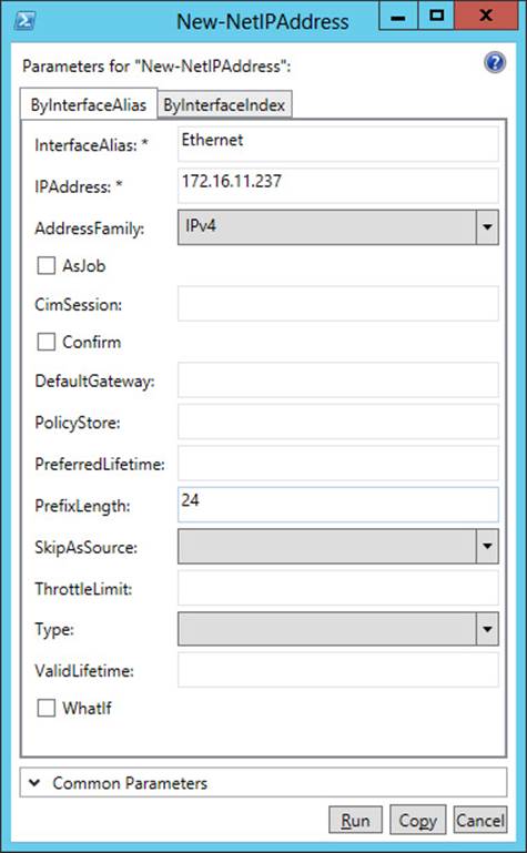
FIGURE 6-7 Add the address 172.16.11.237/24 to the interface named Ethernet.
If you click Copy in the properties page shown in Figure 6-7, the command is copied to the clipboard. The resulting command looks like this:
New-NetIPAddress -InterfaceAlias Ethernet -IPAddress 172.16.11.237 `
-AddressFamily IPv4 -PrefixLength 24
If you click Run, the command executes. By using –InterfaceAlias with the Get-NetIPAddress cmdlet again, you can verify that the command accomplished the desired result:
PS C:\> Get-NetIPAddress -InterfaceAlias Ethernet
IPAddress : fe80::cf8:11a1:2e3:d9bc%12
InterfaceIndex : 12
InterfaceAlias : Ethernet
AddressFamily : IPv6
Type : Unicast
PrefixLength : 64
PrefixOrigin : WellKnown
SuffixOrigin : Link
AddressState : Preferred
ValidLifetime : Infinite ([TimeSpan]::MaxValue)
PreferredLifetime : Infinite ([TimeSpan]::MaxValue)
SkipAsSource : False
PolicyStore : ActiveStore
IPAddress : 172.16.11.237
InterfaceIndex : 12
InterfaceAlias : Ethernet
AddressFamily : IPv4
Type : Unicast
PrefixLength : 24
PrefixOrigin : Manual
SuffixOrigin : Manual
AddressState : Preferred
ValidLifetime : Infinite ([TimeSpan]::MaxValue)
PreferredLifetime : Infinite ([TimeSpan]::MaxValue)
SkipAsSource : False
PolicyStore : ActiveStore
IPAddress : 172.16.11.236
InterfaceIndex : 12
InterfaceAlias : Ethernet
AddressFamily : IPv4
Type : Unicast
PrefixLength : 24
PrefixOrigin : Manual
SuffixOrigin : Manual
AddressState : Preferred
ValidLifetime : Infinite ([TimeSpan]::MaxValue)
PreferredLifetime : Infinite ([TimeSpan]::MaxValue)
SkipAsSource : False
PolicyStore : ActiveStore
Opening the Advanced TCP/IP Settings for the interface from the Network Connections folder confirms the result. (See Figure 6-8.)
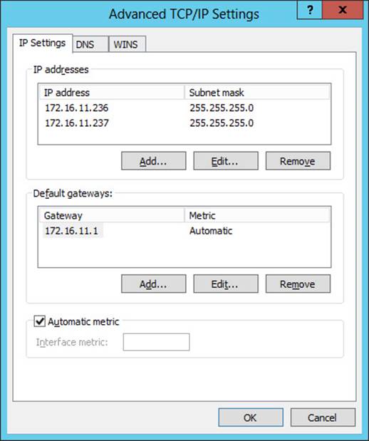
FIGURE 6-8 The Advanced TCP/IP Settings dialog box confirms that the second IP address was successfully added to the interface.
![]() Quick check
Quick check
![]() What cmdlet would you use to remove an existing IP address from a network interface? (Hint: Examine the list of the cmdlets and functions in the NetTCPIP module.)
What cmdlet would you use to remove an existing IP address from a network interface? (Hint: Examine the list of the cmdlets and functions in the NetTCPIP module.)
Quick check answer
![]() A good guess would be the Remove-NetIPAddress cmdlet!
A good guess would be the Remove-NetIPAddress cmdlet!
Examples of network-administration tasks
The best way to learn how to use Windows PowerShell to administer network settings and services on Windows Server 2012 and Windows Server 2012 R2 is to experiment with performing different tasks in a test environment. The following sections provide some examples of what you can do in this area, and the practice and suggested practice exercises included in this chapter present you with further challenges for learning these skills.
Real World: Importance of learning Windows PowerShell
Windows Server 2012 and Windows Server 2012 R2 provide businesses with a foundation they can use for building private and public clouds. If doing this is part of your job as an administrator, you need to become efficient at using Windows PowerShell. That’s because the cloud requires automation to function as intended and Windows PowerShell is Microsoft’s platform for automating server-administration tasks. To increase your job skills in this area, commit yourself to doing more than just reading the lessons and performing the exercises in this book. Make sure you also spend time just experimenting with using different Windows PowerShell cmdlets to learn about their various capabilities and, occasionally, their foibles.
Displaying network adapters with 100 Mbps link speed
You can use the Get-NetAdapter cmdlet to display all network adapters on the server that have a link speed of 100 megabits per second (Mbps) like this:
PS C:\> Get-NetAdapter | Where-Object -FilterScript {$_.LinkSpeed -eq "100 Mbps"}
Name InterfaceDescription ifIndex Status MacAddress LinkSpeed
---- -------------------- ------- ------ ---------- ---------
Ethernet 2 Broadcom NetXtreme Gig... 13 Up A4-BA-DB-0A-96-0C 100 Mbps
Ethernet Broadcom NetXtreme Gig... 12 Up A4-BA-DB-0A-96-0B 100 Mbps
The output of this command consists of objects that can be passed through the pipeline to other cmdlets. For example, you could pipe the output into the Set-NetIPInterface cmdlet to assign a metric value of 5 to all interfaces having a link speed of 100 Mbps as follows:
PS C:\> Get-NetAdapter | Where-Object -FilterScript {$_.LinkSpeed -eq "100 Mbps"} | `
Set-NetIPInterface -InterfaceMetric 5
Disabling a binding on a network adapter
You can enable and disable bindings on a network adapter using Windows PowerShell. For example, start by using the Get-NetAdapterBinding cmdlet to display the bindings for the specified interface:
PS C:\> Get-NetAdapterBinding -InterfaceAlias "Ethernet 2"
Name DisplayName ComponentID Enabled
---- ----------- ----------- -------
Ethernet 2 Hyper-V Extensible Virtual Switch vms_pp False
Ethernet 2 Link-Layer Topology Discovery Responder ms_rspndr True
Ethernet 2 Link-Layer Topology Discovery Mapper I/O Driver ms_lltdio True
Ethernet 2 Microsoft Network Adapter Multiplexor Protocol ms_implat False
Ethernet 2 Client for Microsoft Networks ms_msclient True
Ethernet 2 Windows Network Virtualization Filter driver ms_netwnv False
Ethernet 2 QoS Packet Scheduler ms_pacer True
Ethernet 2 File and Printer Sharing for Microsoft Networks ms_server True
Ethernet 2 Internet Protocol Version 6 (TCP/IPv6) ms_tcpip6 True
Ethernet 2 Internet Protocol Version 4 (TCP/IPv4) ms_tcpip True
To disable a specific binding such as QoS Packet Scheduler, you can use the DisableNetAdapterBinding cmdlet like this:
PS C:\> Disable-NetAdapterBinding -Name "Ethernet 2" -ComponentID ms_pacer
You can use the Enable-NetAdapterBinding cmdlet to reenable the binding.
Disabling a network adapter
You can disable a specific network adapter or even all network adapters using Windows PowerShell. For example, the following command disables the adapter named Ethernet 2 with no confirmation prompt displayed:
PS C:\> Disable-NetAdapter -Name "Ethernet 2" -Confirm:$false
To disable all network adapters on the server, you can use this command:
PS C:\> Disable-NetAdapter -Name *
Note that all remote connectivity with the server will be lost if you do this.
To enable any network adapters that are disabled, you can use the Enable-NetAdapter cmdlet.
Creating a DHCP server scope
You can manage Windows Server 2012 or Windows Server 2012 R2 DHCP servers using Windows PowerShell. Common DHCP server-management tasks include creating scopes, creating exclusion ranges, creating reservations, configuring scope and server options, and so on.
For example, begin by viewing all the scopes currently configured on the DHCP server:
PS C:\> Get-DhcpServerv4Scope
ScopeId SubnetMask Name State StartRange EndRange LeaseDuration
------- ---------- ---- ----- ---------- -------- -------------
172.16.11.0 255.255.255.0 test Active 172.16.11.35 172.16.11.39 8.00:00:00
Note that there is currently only one active scope on the DHCP server. Now add a second scope for the IP address range 172.16.12.50 through 172.16.11.100. Leave the scope inactive until you finish configuring exclusions and reservations for it:
PS C:\> Add-DhcpServerv4Scope -EndRange 172.16.12.100 -Name test2 `
-StartRange 172.16.12.50 -SubnetMask 255.255.255.0 -State InActive
Note that in this cmdlet the order in which you specify the parameters doesn’t matter because you specified the end of the address range before specifying its beginning.
Running Get-DdhpServerv4Scope again indicates that adding the new scope was successful:
PS C:\> Get-DhcpServerv4Scope
ScopeId SubnetMask Name State StartRange EndRange LeaseDuration
------- ---------- ---- ----- ---------- -------- -------------
172.16.11.0 255.255.255.0 test Active 172.16.11.35 172.16.11.39 8.00:00:00
172.16.12.0 255.255.255.0 test2 Inactive 172.16.12.50 172.16.12.100 8.00:00:00
Now exclude the range 172.16.12.70 through 172.16.12.75 from the new scope:
PS C:\> Add-DhcpServerv4ExclusionRange -EndRange 172.16.12.75 -ScopeId 172.16.12.0 `
-StartRange 172.16.12.70
Also add a reservation for a file server:
PS C:\> Add-DhcpServerv4Reservation -ClientId EE-05-B0-DA-04-00 `
-IPAddress 172.16.12.88 -ScopeId 172.16.12.0 `
-Description "Reservation for file server"
Here, EE-05-B0-DA-04-00 represents the MAC address of the file server’s network adapter.
Configure a default gateway address for the new scope by creating a scope option as follows:
PS C:\> Set-DhcpServerv4OptionValue -Router 172.16.12.1 -ScopeId 172.16.12.0
If you want to create a server option instead of a scope option, you could do this by omitting the –ScopeID parameter from the preceding command.
Now you’re done creating and configuring the new scope, so finish by activating it:
PS C:\> Set-DhcpServerv4Scope -State Active
Note: Why doesn’t Get-Command display the expected results?
If you run the command Get-Command *dhcp* on a clean install of Windows Server 2012 or Windows Server 2012 R2, you won’t get any results. That’s because Get-Command can display commands only for Windows PowerShell modules that are installed on the server, and the module for DHCP isn’t installed until you add the DHCP Server role to your server.
Creating DNS resource records
You can manage Windows Server 2012 or Windows Server 2012 R2 DNS servers using Windows PowerShell. Common DNS server-management tasks include adding resource records to zones, configuring forwarders, configuring root hints, and so on.
For example, view a list of zones on a DNS server that is also a domain controller for the corp.contoso.com domain:
PS C:\> Get-DnsServerZone
ZoneName ZoneType IsAutoCreated IsDsIntegrated IsRever... IsSigned
-------- -------- ------------- -------------- ------- --------
_msdcs.corp.contoso.com Primary False True False True
0.in-addr.arpa Primary True False True False
127.in-addr.arpa Primary True False True False
255.in-addr.arpa Primary True False True False
corp.contoso.com Primary False True False False
TrustAnchors Primary False True False False
To view a list of resource records of type A (address) in the corp.contoso.com zone, you can pipe the output of the Get-DnsServerResourceRecord cmdlet into the Where-Object cmdlet, like this:
PS C:\> Get-DnsServerResourceRecord -ZoneName corp.contoso.com | Where-Object
{$_.RecordType -eq "A"}
HostName RecordType Timestamp TimeToLive RecordData
-------- ---------- --------- ---------- ----------
@ A 7/8/2012 12:00:00 PM 00:10:00 172.16.11.36
@ A 7/8/2012 1:00:00 PM 00:10:00 172.16.11.232
DomainDnsZones A 7/8/2012 12:00:00 PM 00:10:00 172.16.11.36
DomainDnsZones A 7/8/2012 12:00:00 PM 00:10:00 172.16.11.232
ForestDnsZones A 7/8/2012 12:00:00 PM 00:10:00 172.16.11.36
ForestDnsZones A 7/8/2012 12:00:00 PM 00:10:00 172.16.11.232
sea-srv-1 A 0 01:00:00 172.16.11.232
SEA-SRV-5 A 0 01:00:00 172.16.11.36
To add a new A resource record for a test server, you can use the Add-DnsServerResourceRecordA cmdlet, like this:
PS C:\> Add-DnsServerResourceRecordA -IPv4Address 172.16.11.239 -Name SEA-TEST `
-ZoneName corp.contoso.com
You can also add other types of resource records—such as PTR, CN, or MX records—using the preceding cmdlet. And you can use the Remove-DnsServerResourceRecord cmdlet to remove resource records from a zone.
There are over 100 different cmdlets in the DnsServer module for Windows PowerShell in Windows Server 2012 and Windows Server 2012 R2. Table 6-1 shows the cmdlets you can use to perform some common DNS administration tasks. You’ll get some hands-on experience with using some of these cmdlets in the practice exercises for this chapter.
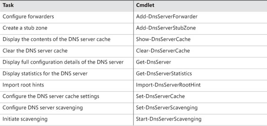
TABLE 6-1 Common DNS server-administration tasks and Windows PowerShell cmdlets you can use to perform them
Troubleshooting networking problems
Both Windows Server 2012 and Windows Server 2012 R2 introduce new Windows PowerShell cmdlets that can help you troubleshoot network connection problems when they occur. We’ve already briefly examined the Get-NetAdapter and Get-NetIPAddress cmdlets that were introduced in Windows Server 2012. We now look at some additional capabilities of these two cmdlets, some other cmdlets, and a few new cmdlets introduced in Windows Server 2012 R2.
Get-NetAdapter and Get-VMNetworkAdapter
The Get-NetAdapter cmdlet was first introduced in Windows Server 2012 to enable you to retrieve the configuration of all physical network adapters in the server. If you’re experiencing what might be a networking issue with one of your servers, the first thing you probably want to check is the configuration of the network adapters. For example, see what happens when you run this command on a Hyper-V host named SERVER1.contoso.com that is running Windows Server 2012 R2:
PS C:\> Get-NetAdapter
Name InterfaceDescription ifIndex Status
---- -------------------- ------- ------
vEthernet (Broadcom Ne... Hyper-V Virtual Ethernet Adapter #2 18 Up
Ethernet Broadcom NetXtreme Gigabit Ethernet 12 Di...
Ethernet 2 Broadcom NetXtreme Gigabit Ethernet #2 13 Up
Because this is a Hyper-V host, there are probably some virtual machines running on it. On Hyper-V hosts running Windows Server 2012 and later, you can use the Get-VMNetworkAdapter cmdlet to collect configuration information for the network adapters for these virtual machines. For example, the following command retrieves information about all virtual machine network adapters on the host:
PS C:\> Get-VMNetworkAdapter *
Name IsManagementOs VMName SwitchName
---- -------------- ------ ----------
Network Adapter False SRV-STANDARD Broadcom NetXtreme Gigabit Ether...
Network Adapter False SRV2012R2 Broadcom NetXtreme Gigabit Ether...
Network Adapter False SRV2012R2
Network Adapter False SRV2012 Broadcom NetXtreme Gigabit Ether...
Network Adapter False SRV2012 Broadcom NetXtreme Gigabit Ether...
Network Adapter False Gen2Test Broadcom NetXtreme Gigabit Ether...
You can also use Get-VMNetworkAdapter with the -VMName parameter to display network adapters for a specific virtual machine on the host.
Get-NetIPAddress
The Get-NetIPAddress cmdlet was first introduced in Windows Server 2012 to enable you to retrieve the IP addresses configured on the system’s network adapters. You can use the Get-NetIPAddress cmdlet both on physical servers and within virtual machines. For example, you can run this command on SERVER1 described above:
PS C:\> Get-NetIPAddress
IPAddress : fe80::8843:1e98:a8a6:6fab%12
InterfaceIndex : 12
InterfaceAlias : Ethernet
AddressFamily : IPv6
Type : Unicast
PrefixLength : 64
PrefixOrigin : WellKnown
SuffixOrigin : Link
AddressState : Deprecated
ValidLifetime : Infinite ([TimeSpan]::MaxValue)
PreferredLifetime : Infinite ([TimeSpan]::MaxValue)
SkipAsSource : False
PolicyStore : ActiveStore
IPAddress : fe80::1905:8ae1:5bfd:7b8e%18
InterfaceIndex : 18
InterfaceAlias : vEthernet (Broadcom NetXtreme Gigabit Ethernet #2 -
Virtual Switch)
AddressFamily : IPv6
Type : Unicast
PrefixLength : 64
PrefixOrigin : WellKnown
SuffixOrigin : Link
AddressState : Preferred
ValidLifetime : Infinite ([TimeSpan]::MaxValue)
PreferredLifetime : Infinite ([TimeSpan]::MaxValue)
SkipAsSource : False
PolicyStore : ActiveStore
IPAddress : fe80::5efe:172.16.11.30%14
InterfaceIndex : 14
InterfaceAlias : isatap.{3D53D3DC-9209-4C7F-8AAE-AD8ADCBD93FC}
AddressFamily : IPv6
Type : Unicast
PrefixLength : 128
PrefixOrigin : WellKnown
SuffixOrigin : Link
AddressState : Deprecated
ValidLifetime : Infinite ([TimeSpan]::MaxValue)
PreferredLifetime : Infinite ([TimeSpan]::MaxValue)
SkipAsSource : False
PolicyStore : ActiveStore
IPAddress : ::1
InterfaceIndex : 1
InterfaceAlias : Loopback Pseudo-Interface 1
AddressFamily : IPv6
Type : Unicast
PrefixLength : 128
PrefixOrigin : WellKnown
SuffixOrigin : WellKnown
AddressState : Preferred
ValidLifetime : Infinite ([TimeSpan]::MaxValue)
PreferredLifetime : Infinite ([TimeSpan]::MaxValue)
SkipAsSource : False
PolicyStore : ActiveStore
IPAddress : 169.254.111.171
InterfaceIndex : 12
InterfaceAlias : Ethernet
AddressFamily : IPv4
Type : Unicast
PrefixLength : 16
PrefixOrigin : WellKnown
SuffixOrigin : Link
AddressState : Tentative
ValidLifetime : Infinite ([TimeSpan]::MaxValue)
PreferredLifetime : Infinite ([TimeSpan]::MaxValue)
SkipAsSource : False
PolicyStore : ActiveStore
IPAddress : 172.16.11.30
InterfaceIndex : 18
InterfaceAlias : vEthernet (Broadcom NetXtreme Gigabit Ethernet #2 -
Virtual Switch)
AddressFamily : IPv4
Type : Unicast
PrefixLength : 24
PrefixOrigin : Manual
SuffixOrigin : Manual
AddressState : Preferred
ValidLifetime : Infinite ([TimeSpan]::MaxValue)
PreferredLifetime : Infinite ([TimeSpan]::MaxValue)
SkipAsSource : False
PolicyStore : ActiveStore
IPAddress : 127.0.0.1
InterfaceIndex : 1
InterfaceAlias : Loopback Pseudo-Interface 1
AddressFamily : IPv4
Type : Unicast
PrefixLength : 8
PrefixOrigin : WellKnown
SuffixOrigin : WellKnown
AddressState : Preferred
ValidLifetime : Infinite ([TimeSpan]::MaxValue)
PreferredLifetime : Infinite ([TimeSpan]::MaxValue)
SkipAsSource : False
PolicyStore : ActiveStore
You can see that Get-NetIPAddress returns a lot of useful information that you can parse or pipe into other commands for further processing.
Get-NetIPConfiguration
The Get-NetIPConfiguration cmdlet was first introduced in Windows Server 2012 to enable you to retrieve able network interfaces, IP addresses, and DNS servers configured on a system. The key value of Get-NetIPConfiguration is that it gives you the big picture of the system’s network configuration in a concise way. For example, see what happens when you run this command on SERVER1 without specifying any further options:
PS C:\> Get-NetIPConfiguration
InterfaceAlias : vEthernet (Broadcom NetXtreme Gigabit Ethernet #2 -
Virtual Switch)
InterfaceIndex : 18
InterfaceDescription : Hyper-V Virtual Ethernet Adapter #2
NetProfile.Name : contoso.com
IPv4Address : 172.16.11.30
IPv6DefaultGateway :
IPv4DefaultGateway : 172.16.11.1
DNSServer : 172.16.11.50
InterfaceAlias : Ethernet
InterfaceIndex : 12
InterfaceDescription : Broadcom NetXtreme Gigabit Ethernet
NetAdapter.Status : Disconnected
To make things even easier, you can use the alias GIP instead of typing Get-NetIPConfiguration at the command line. For example, say you want to retrieve only the DNS Server configuration of the network adapter whose alias begins with vEthernet as shown above. Here’s how you can do this:
PS C:\> $a = GIP 'v*'
PS C:\> $a.DNSServer
InterfaceAlias Interface Address ServerAddresses PSComputerName
Index Family
-------------- --------- ------- --------------- --------------
vEthernet (Broadcom NetXt... 18 IPv6 {}
vEthernet (Broadcom NetXt... 18 IPv4 {172.16.11.50}
Get-NetIPConfiguration can also provide verbose output if you specify the -Detailed parameter as shown here:
PS C:\> GIP -Detailed
ComputerName : SERVER1
InterfaceAlias : vEthernet (Broadcom NetXtreme Gigabit Ethernet
#2 - Virtual Switch)
InterfaceIndex : 18
InterfaceDescription : Hyper-V Virtual Ethernet Adapter #2
NetAdapter.LinkLayerAddress : 00-24-E8-50-17-F3
NetAdapter.Status : Up
NetProfile.Name : contoso.com
NetProfile.NetworkCategory : DomainAuthenticated
NetProfile.IPv6Connectivity : LocalNetwork
NetProfile.IPv4Connectivity : Internet
IPv6LinkLocalAddress : fe80::1905:8ae1:5bfd:7b8e%18
IPv4Address : 172.16.11.30
IPv6DefaultGateway :
IPv4DefaultGateway : 172.16.11.1
NetIPv6Interface.NlMTU : 1500
NetIPv4Interface.NlMTU : 1500
NetIPv6Interface.DHCP : Enabled
NetIPv4Interface.DHCP : Disabled
DNSServer : 172.16.11.50
ComputerName : SERVER1
InterfaceAlias : Ethernet
InterfaceIndex : 12
InterfaceDescription : Broadcom NetXtreme Gigabit Ethernet
NetAdapter.LinkLayerAddress : 00-24-E8-50-17-F4
NetAdapter.Status : Disconnected
Test-NetConnection
The Test-NetConnection cmdlet has been introduced in Windows Server 2012 R2 to enable you to perform ICMP and TCP connectivity tests. To see how this cmdlet can be used, perform some tests from a Windows PowerShell prompt on the same server named SERVER1.contoso.com described previously.
First, test network connectivity between SERVER1 and another server named SERVER2 on the network:
PS C:\> Test-NetConnection SERVER2.contoso.com
ComputerName : SERVER2.contoso.com
RemoteAddress : 172.16.11.50
InterfaceAlias : vEthernet (Broadcom NetXtreme Gigabit Ethernet #2 -
Virtual Switch)
SourceAddress : 172.16.11.30
PingSucceeded : True
PingReplyDetails (RTT) : 0 ms
You can also use the Test-NetConnection cmdlet to test network connectivity with hosts on remote networks and over the Internet. For example, see if SERVER1 can establish network connectivity with the Microsoft Xbox website:
PS C:\> Test-NetConnection www.xbox.com
ComputerName : www.xbox.com
RemoteAddress : 184.29.219.150
InterfaceAlias : vEthernet (Broadcom NetXtreme Gigabit Ethernet #2 -
Virtual Switch)
SourceAddress : 172.16.11.30
PingSucceeded : True
PingReplyDetails (RTT) : 26 ms
You can also use the -TraceRoute parameter to trace the exact network route used to establish connectivity with the remote site:
PS C:\> Test-NetConnection www.xbox.com -TraceRoute
ComputerName : www.xbox.com
RemoteAddress : 184.29.219.150
InterfaceAlias : vEthernet (Broadcom NetXtreme Gigabit Ethernet #2 -
Virtual Switch)
SourceAddress : 172.16.11.30
PingSucceeded : True
PingReplyDetails (RTT) : 29 ms
TraceRoute : 172.16.11.1
142.161.5.200
142.161.5.65
4.28.68.21
4.69.158.146
4.69.138.166
4.68.111.70
184.29.219.150
You can also use Test-NetConnection to test connectivity on a specific TCP port by including the -Port parameter in your command. For example, you can verify that the Xbox website can be accessed on the standard HTTP port, which is TCP port 80:
PS C:\> Test-NetConnection www.xbox.com -Port 80
ComputerName : www.xbox.com
RemoteAddress : 184.29.219.150
RemotePort : 80
InterfaceAlias : vEthernet (Broadcom NetXtreme Gigabit Ethernet #2 -
Virtual Switch)
SourceAddress : 172.16.11.30
PingSucceeded : True
PingReplyDetails (RTT) : 28 ms
TcpTestSucceeded : True
You can also use an alias like RDP to verify TCP connectivity with the well-known port for the Remote Desktop Protocol (RDP), which is TCP port 3389. For example, you can see if SERVER1 can establish connectivity to TCP port 3389 on SERVER2:
PS C:\> Test-NetConnection SERVER2 RDP
ComputerName : SERVER2
RemoteAddress : 172.16.11.50
RemotePort : 3389
InterfaceAlias : vEthernet (Broadcom NetXtreme Gigabit Ethernet #2 -
Virtual Switch)
SourceAddress : 172.16.11.30
PingSucceeded : True
PingReplyDetails (RTT) : 0 ms
TcpTestSucceeded : True
The success of the above test indicates that Remote Desktop is enabled on the server SERVER2.
Test-NetConnection also lets you use other aliases besides RDP for testing connectivity with well-known TCP ports. For example, you can also use the following:
![]() SMB
SMB
![]() HTTP
HTTP
![]() PING
PING
Now see what happens when you try the RDP test against the server HOST40 on the network:
PS C:\> Test-NetConnection HOST40 RDP
WARNING: Ping to HOST40 failed -- Status: TimedOut
ComputerName : HOST40
RemoteAddress : 172.16.11.61
RemotePort : 3389
InterfaceAlias : vEthernet (Broadcom NetXtreme Gigabit Ethernet #2 -
Virtual Switch)
SourceAddress : 172.16.11.30
PingSucceeded : False
PingReplyDetails (RTT) : 0 ms
TcpTestSucceeded : True
Note that RDP connectivity succeeded but pinging the server failed. This indicates that the server’s firewall is active and blocking the inbound ICMP messages that are being sent by SERVER1.
The Test-NetConnection cmdlet also supports an -InformationLevel parameter that enables you to gather more detailed information concerning the connectivity test being performed:
PS C:\> Test-NetConnection SERVER2 RDP -InformationLevel Detailed
ComputerName : SERVER2
RemoteAddress : 172.16.11.50
RemotePort : 3389
AllNameResolutionResults : 172.16.11.50
fe80::396f:7162:ab64:fa82
MatchingIPsecRules :
NetworkIsolationContext : Private Network
InterfaceAlias : vEthernet (Broadcom NetXtreme Gigabit Ethernet #2 -
Virtual Switch)
SourceAddress : 172.16.11.30
NetRoute (NextHop) : 0.0.0.0
PingSucceeded : True
PingReplyDetails (RTT) : 0 ms
TcpTestSucceeded : True
You also can use -InformationLevel to suppress all output except whether the desired test was successful:
PS C:\> Test-NetConnection HOST40 RDP -InformationLevel Quiet
WARNING: Ping to HOST40 failed -- Status: TimedOut
True
PS C:\>
One final note about Test-NetConnection is that you can also run it with no parameters, like this:
PS C:\> Test-NetConnection
ComputerName : internetbeacon.msedge.net
RemoteAddress : 131.253.3.197
InterfaceAlias : vEthernet (Broadcom NetXtreme Gigabit Ethernet #2 -
Virtual Switch)
SourceAddress : 172.16.11.30
PingSucceeded : True
PingReplyDetails (RTT) : 49 ms
Doing this just tests whether your server has a network connection with the Internet by testing connectivity with a remote server belonging to the DNS domain msedge.net, which is registered by Microsoft.
Lesson summary
![]() The Get-Command cmdlet can help identify possible cmdlets for performing a specific administration task.
The Get-Command cmdlet can help identify possible cmdlets for performing a specific administration task.
![]() The Show-Command cmdlet is useful for learning the syntax of other cmdlets.
The Show-Command cmdlet is useful for learning the syntax of other cmdlets.
![]() You can view and configure the TCP/IP configuration of a network interface, including its IP address settings, by using Windows PowerShell.
You can view and configure the TCP/IP configuration of a network interface, including its IP address settings, by using Windows PowerShell.
![]() You can identify, configure, manage, enable, and disable network adapters by using Windows PowerShell.
You can identify, configure, manage, enable, and disable network adapters by using Windows PowerShell.
![]() You can display, configure, and manage DHCP server properties, scopes, exclusion ranges, reservations, and options by using Windows PowerShell.
You can display, configure, and manage DHCP server properties, scopes, exclusion ranges, reservations, and options by using Windows PowerShell.
![]() You can display, configure, and manage DNS server properties, zones, resource records, forwarders, cache settings, and replication by using Windows PowerShell.
You can display, configure, and manage DNS server properties, zones, resource records, forwarders, cache settings, and replication by using Windows PowerShell.
Lesson review
Answer the following questions to test your knowledge of the information in this lesson. You can find the answers to these questions and explanations of why each answer choice is correct or incorrect in the “Answers” section at the end of this chapter.
1. When you use Show-Command to open a properties page for a cmdlet, what does an asterisk (*) mean when you find one beside a parameter?
A. The parameter is optional.
B. The parameter is mandatory.
C. The parameter does not apply to that cmdlet.
D. The parameter can be specified only from the command line.
2. Which cmdlet can you use to disable a binding on a network adapter?
A. Get-NetAdapterBinding
B. Remove-NetAdapterBinding
C. Disable-NetAdapterBinding
D. Disable-NetAdapter
3. What action does the following command perform?
Set-DhcpServerv4OptionValue -Router 10.10.0.1 -ScopeId 10.10.20.0
A. Configures a DHCP server option that assigns the address 10.10.0.1 as the default gateway on any DHCP client whose IPv4 address is on the 10.10.20.0 subnet
B. Configures a DHCP scope option that assigns the address 10.10.0.1 as the default gateway on any DHCP client whose IPv4 address is on the 10.10.20.0 subnet
C. Configures a DHCP server option that assigns the address 10.10.0.1 to a router on the 10.10.20.0 subnet
D. Configures a DHCP scope option that assigns the address 10.10.0.1 to a router on the 10.10.20.0 subnet
Lesson 4: Configuring IPv6/IPv4 interoperability
An increasingly important part of the administrator’s role is to prepare the organization’s network for migration to Internet Protocol version 6 (IPv6). The reasons for this include the exponential growth of the Internet, the proliferation of mobile devices that need to be able to connect to the corporate network, and the impending exhaustion of the IPv4 address space. Unfortunately, many administrators still lack an understanding of basic IPv6 concepts and the necessary skills. This lesson provides an overview of IPv6 concepts and technologies as they relate to Windows-based networks and describes how to implement several IPv6 transition technologies as part of an overall IPv6 migration plan.
After this lesson, you will be able to:
![]() Understand basic IPv6 concepts and terminology.
Understand basic IPv6 concepts and terminology.
![]() Understand the dual IP layer architecture of the TCP/IP networking stack and how to disable IPv6 functionality.
Understand the dual IP layer architecture of the TCP/IP networking stack and how to disable IPv6 functionality.
![]() Understand how IPv6 addressing works and the different types of IPv6 addresses.
Understand how IPv6 addressing works and the different types of IPv6 addresses.
![]() Understand the different ways IPv6 addresses can be assigned, including manual addressing, stateless address autoconfiguration, and stateful address autoconfiguration.
Understand the different ways IPv6 addresses can be assigned, including manual addressing, stateless address autoconfiguration, and stateful address autoconfiguration.
![]() Configure a DHCPv6 server for stateless and stateful address autoconfiguration.
Configure a DHCPv6 server for stateless and stateful address autoconfiguration.
![]() Describe the different IPv6 transition technologies.
Describe the different IPv6 transition technologies.
![]() Configure Intra-Site Automatic Tunnel Addressing Protocol (ISATAP).
Configure Intra-Site Automatic Tunnel Addressing Protocol (ISATAP).
Estimated lesson time: 30 minutes
IPv6 concepts and terminology
Although some IPv6 concepts and terminology are similar to those for IPv4, others are quite different. The following list is a brief summary of some of the important IPv6 terminology with which you should be familiar when you begin developing an IPv6 migration plan for your organization. Figure 6-9 illustrates how many of these concepts are interrelated. Additional IPv6 terminology is introduced later in this lesson when appropriate.
![]() Node A device that can be configured with an IPv6 address. Examples of nodes include hosts and routers.
Node A device that can be configured with an IPv6 address. Examples of nodes include hosts and routers.
![]() Host A node that can be either the source of or a destination for IPv6 traffic. Hosts are not able to forward IPv6 packets that are explicitly addressed to them. Instead, they silently discard such packets.
Host A node that can be either the source of or a destination for IPv6 traffic. Hosts are not able to forward IPv6 packets that are explicitly addressed to them. Instead, they silently discard such packets.
![]() Router A node that is able to forward IPv6 packets not explicitly addressed to itself. Routers advertise their presence on a network. They also advertise host configuration information.
Router A node that is able to forward IPv6 packets not explicitly addressed to itself. Routers advertise their presence on a network. They also advertise host configuration information.
![]() Link A collection of network interfaces that use the same 64-bit IPv6 unicast address prefix, which includes hosts but not routers. Links are bounded by routers and are also referred to as network segments or subnets.
Link A collection of network interfaces that use the same 64-bit IPv6 unicast address prefix, which includes hosts but not routers. Links are bounded by routers and are also referred to as network segments or subnets.
![]() Interface A representation for how a node is attached to a link. An interface can be either of the following:
Interface A representation for how a node is attached to a link. An interface can be either of the following:
![]() Physical For example, a network adapter in a server
Physical For example, a network adapter in a server
![]() Logical For example, a tunnel interface that encapsulates IPv6 packets inside an IPv4 header to send IPv6 traffic over an IPv4-only network
Logical For example, a tunnel interface that encapsulates IPv6 packets inside an IPv4 header to send IPv6 traffic over an IPv4-only network
![]() Address An identifier that designates either the source of or destination for an IPv6 packet. IPv6 addresses are assigned at the IPv6 layer of an interface. The different types of IPv6 addresses are described later in this lesson.
Address An identifier that designates either the source of or destination for an IPv6 packet. IPv6 addresses are assigned at the IPv6 layer of an interface. The different types of IPv6 addresses are described later in this lesson.
![]() Neighbors Nodes connected to the same link. In IPv6, neighbors are able to detect and monitor reachability with one another by using a process called Neighbor Discovery.
Neighbors Nodes connected to the same link. In IPv6, neighbors are able to detect and monitor reachability with one another by using a process called Neighbor Discovery.
![]() Network Two or more links connected by routers.
Network Two or more links connected by routers.
![]() Site An autonomously operated IPv6 network that is connected to the IPv6 Internet.
Site An autonomously operated IPv6 network that is connected to the IPv6 Internet.
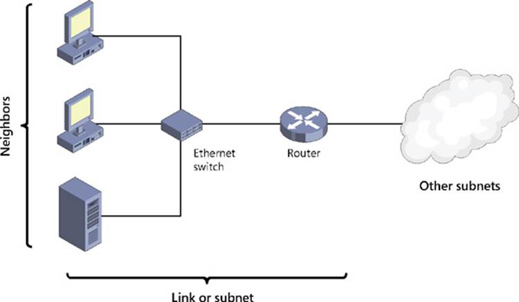
FIGURE 6-9 Review basic IPv6 networking concepts.
IPv6 and the TCP/IP protocol architecture
As Figure 6-10 illustrates, the TCP/IP protocol networking stack on the Microsoft Windows platform is implemented using a dual IP layer approach. This means, for example, that
![]() Only a single implementation of transport layer protocols—such as Transmission Control Protocol (TCP) and User Datagram Protocol (UDP)—is needed for both IPv4 and IPv6 communications.
Only a single implementation of transport layer protocols—such as Transmission Control Protocol (TCP) and User Datagram Protocol (UDP)—is needed for both IPv4 and IPv6 communications.
![]() Only a single implementation of framing layer protocols—such as Ethernet (802.3), Point-to-Point Protocol (PPP), and mobile broadband (802.11)—is needed for both IPv4 and IPv6 communications.
Only a single implementation of framing layer protocols—such as Ethernet (802.3), Point-to-Point Protocol (PPP), and mobile broadband (802.11)—is needed for both IPv4 and IPv6 communications.
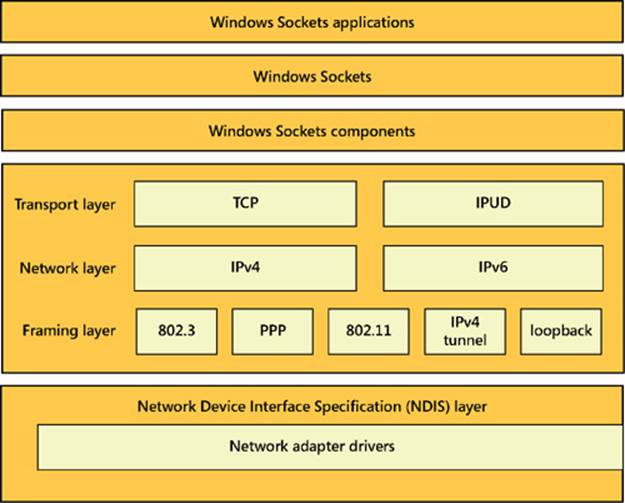
FIGURE 6-10 The TCP/IP protocol stack is implemented using a dual IP layer approach.
This dual IP layer TCP/IP stack is implemented on the following Windows platforms:
![]() Windows 8.1
Windows 8.1
![]() Windows 8
Windows 8
![]() Windows 7
Windows 7
![]() Windows Vista
Windows Vista
![]() Windows Server 2012 R2
Windows Server 2012 R2
![]() Windows Server 2012
Windows Server 2012
![]() Windows Server 2008 R2
Windows Server 2008 R2
![]() Windows Server 2008
Windows Server 2008
Note: IPv6 on Windows platforms
Because IPv6 functionality is essentially the same on Windows 8.1, Windows 8, Windows 7, Windows Vista, Windows Server 2012 R2, Windows Server 2012, Windows Server 2008 R2, and Windows Server 2008, all information presented in the remainder of this lesson applies to these specific Windows platforms unless explicitly stated otherwise. IPv6 functionality in earlier Windows platforms, such as Windows XP and Windows 2003, is more limited and therefore is not covered in this lesson.
Default IPv6 functionality
On Windows platforms, IPv6 is installed by default and cannot be uninstalled because it is a fundamental component of Tcpip.sys, the TCP/IP driver file on these platforms. IPv6 is also enabled by default for all connections in the Network Connections folder on a Windows computer. To verify this, open the properties of a network connection, select the Networking tab, and check that Internet Protocol Version 6 (TCP/IPv6) is selected, as shown in Figure 6-11.
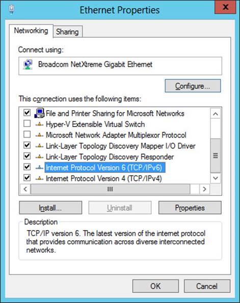
FIGURE 6-11 IPv6 is enabled by default on Windows Server 2012 and Windows Server 2012 R2.
IPv6 is also preferred over IPv4 for network communications by Windows computers. For example, if a DNS server returns both IPv4 and IPv6 addresses in response to a name query, Windows will first try to communicate with the remote host using IPv6. If this fails, Windows will then attempt to use IPv4.
Disabling IPv6
Although you cannot uninstall IPv6 on Windows platforms, you can disable it if desired. However, Microsoft does not recommend disabling IPv6 for the following reasons:
![]() During the development of Windows platforms by Microsoft, services and applications were tested only with IPv6 enabled. As a result, Microsoft cannot predict the possible consequences of disabling IPv6 on Windows.
During the development of Windows platforms by Microsoft, services and applications were tested only with IPv6 enabled. As a result, Microsoft cannot predict the possible consequences of disabling IPv6 on Windows.
![]() Some Windows features will not function if IPv6 is disabled. Examples of such features include DirectAccess and Remote Assistance.
Some Windows features will not function if IPv6 is disabled. Examples of such features include DirectAccess and Remote Assistance.
By leaving IPv6 enabled, you ensure that your Windows computers are fully supported and that all network-enabled features can work as intended. However, if you decide you need to disable IPv6 on a Windows computer for some reason, there are several ways you can do this. For example, if you want to disable IPv6 for a specific local area network (LAN) interface on a Windows computer, you can do so by deselecting Internet Protocol Version 6 (TCP/IPv6) on the Networking tab of the connection’s properties, as shown previously in Figure 6-11. Note, however, that performing this action does not disable IPv6 for either the loopback interface or any tunnel interfaces on the computer.
To disable specific types of IPv6 functionality for all interfaces on a Windows computer, perform the following steps:
1. Create a new DWORD registry value named DisabledComponents under the following registry key:
HKLM\SYSTEM\CurrentControlSet\Services\tcpip6\Parameters\
2. Create an 8-bit binary that defines the types of IPv6 functionality you want to disable by using the following information:
![]() Bit 0 Set this bit to 1 to disable all IPv6 tunnel interfaces, including ISATAP, Teredo, 6to4, and IP-HTTPS, or set it to 0 to leave all IPv6 tunnel interfaces enabled.
Bit 0 Set this bit to 1 to disable all IPv6 tunnel interfaces, including ISATAP, Teredo, 6to4, and IP-HTTPS, or set it to 0 to leave all IPv6 tunnel interfaces enabled.
![]() Bit 1 Set this bit to 1 to disable all 6to4 tunnel interfaces or set it to 0 to leave all 6to4 tunnel interfaces enabled.
Bit 1 Set this bit to 1 to disable all 6to4 tunnel interfaces or set it to 0 to leave all 6to4 tunnel interfaces enabled.
![]() Bit 2 Set this bit to 1 to disable all ISATAP-based interfaces or set it to 0 to leave all ISATAP-based interfaces enabled.
Bit 2 Set this bit to 1 to disable all ISATAP-based interfaces or set it to 0 to leave all ISATAP-based interfaces enabled.
![]() Bit 3 Set this bit to 1 to disable all Teredo-based interfaces or set it to 0 to leave all Teredo-based interfaces enabled.
Bit 3 Set this bit to 1 to disable all Teredo-based interfaces or set it to 0 to leave all Teredo-based interfaces enabled.
![]() Bit 4 Set this bit to 1 to disable IPv6 for all nontunnel interfaces, including LAN and PPP interfaces, or set it to 0 to leave all nontunnel interfaces enabled.
Bit 4 Set this bit to 1 to disable IPv6 for all nontunnel interfaces, including LAN and PPP interfaces, or set it to 0 to leave all nontunnel interfaces enabled.
![]() Bit 5 Set this bit to 1 to configure the default prefix table so that IPv4 is preferred over IPv6 when attempting to establish a network connection or set it to 0 to leave IPv6 as the preferred network layer protocol.
Bit 5 Set this bit to 1 to configure the default prefix table so that IPv4 is preferred over IPv6 when attempting to establish a network connection or set it to 0 to leave IPv6 as the preferred network layer protocol.
![]() Bit 6 Leave this bit set to 0 because it is reserved for future use.
Bit 6 Leave this bit set to 0 because it is reserved for future use.
![]() Bit 7 Set this bit to 1 to disable all IP-HTTPS-based interfaces or set it to 0 to leave all IP-HTTPS-based interfaces enabled.
Bit 7 Set this bit to 1 to disable all IP-HTTPS-based interfaces or set it to 0 to leave all IP-HTTPS-based interfaces enabled.
3. Convert the binary number you created into hexadecimal form and assign it as the value for the DisabledComponents registry value. Remember that bit 7 is the leftmost bit and bit 0 is the rightmost bit of the binary number.
4. Restart the computer to have the changes take effect.
For example, say you want to disable both Teredo and 6to4 on a Windows computer but leave ISATAP and all other IPv6 functionality enabled. To do this, you need to assign values to bits 0 through 7 as follows:
![]() Bit 0 0
Bit 0 0
![]() Bit 1 1
Bit 1 1
![]() Bit 2 0
Bit 2 0
![]() Bit 3 1
Bit 3 1
![]() Bit 4 0
Bit 4 0
![]() Bit 5 0
Bit 5 0
![]() Bit 6 0
Bit 6 0
![]() Bit 7 0
Bit 7 0
The binary number 00001010 converted to hexadecimal form is 0xA, and this is the value you would assign to the DisabledComponents registry value.
![]() Quick check
Quick check
![]() What effect will the value 0x21 have when it is assigned to a newly created DisabledComponents registry value on a Windows computer?
What effect will the value 0x21 have when it is assigned to a newly created DisabledComponents registry value on a Windows computer?
Quick check answer
![]() The hexadecimal number 0x21 converted to binary form is 00100001, which means that bits 0 and 5 have the value 1. Assigning this value to the DisabledComponents registry value will do two things. First, it will cause IPv4 to be preferred over IPv6 when the computer attempts to establish network communications. Second, it will disable all IPv6 tunnel interfaces on the computer.
The hexadecimal number 0x21 converted to binary form is 00100001, which means that bits 0 and 5 have the value 1. Assigning this value to the DisabledComponents registry value will do two things. First, it will cause IPv4 to be preferred over IPv6 when the computer attempts to establish network communications. Second, it will disable all IPv6 tunnel interfaces on the computer.
IPv6 addressing
In contrast to the 32-bit (4-byte) addresses used by the IPv4 protocol, IPv6 uses 128-bit (16-byte) addresses. Using addresses that are four times longer increases the theoretically usable address space from 232 addresses (approximately 4 billion addresses) to 2128 addresses (approximately 3.4 × 1038 addresses). The actual address space for IPv6 is smaller, however, because of the hierarchical way that IPv6 addresses are constructed. Specifically, each 128-bit IPv6 address consists of two parts:
![]() A 64-bit IPv6 prefix that indicates the address type, how packets containing the address should be routed, the subnet on which the interface having the address resides, or some combination of these types of information
A 64-bit IPv6 prefix that indicates the address type, how packets containing the address should be routed, the subnet on which the interface having the address resides, or some combination of these types of information
![]() A 64-bit IPv6 interface identifier that identifies the interface on the subnet
A 64-bit IPv6 interface identifier that identifies the interface on the subnet
IPv6 address representation
IPv4 addresses are usually represented in the familiar dotted-decimal form, such as 65.55.58.201, in which each number represents 8 bits of the 32-bit address. By contrast, the much longer IPv6 addresses are typically represented by dividing the 128-bit address into 16-bit (4-byte) segments. Each segment is then converted from binary format to a 4-bit hexadecimal number and these numbers are separated by using colons.
For example, when expressed in binary form, the following IPv6 address spans two lines of text on this page:
0010000000000001000011011011100000111111101010010000000000000000
0000000000000000000000000000000000000000110100111001110001011010
When converted into colon hexadecimal notation, the address is much shorter:
2001:0DB8:3FA9:0000:0000:0000:00D3:9C5A
The preceding address can be further compressed by suppressing leading zeros as follows:
2001:DB8:3FA9:0:0:0:D3:9C5A
Even further compression can be achieved by representing contiguous blocks of hexadecimal zeros as double colons as follows:
2001:DB8:3FA9::D3:9C5A
Note: Double-colon notation
To ensure unambiguous representation, you can use only one double colon when representing an IPv6 address.
IPv6 prefixes
The first 64 bits of a 128-bit IPv6 address represent the IPv6 prefix for the address. An IPv6 prefix can be used to
![]() Specify the type of the IPv6 address.
Specify the type of the IPv6 address.
![]() Define a summarized route.
Define a summarized route.
![]() Indicate a subnet.
Indicate a subnet.
For example, the IPv6 prefix portion of the IPv6 address 2001:DB8:3FA9::D3:9C5A used in the previous section is 2001:DB8:3FA9:0.
IPv6 prefixes are expressed using an <address>/<prefix_length> format that is similar to the Classless Interdomain Routing (CIDR) notation used on IPv4 networks. The value of <prefix_length> can vary as follows:
![]() Subnets always have a prefix length of 64.
Subnets always have a prefix length of 64.
![]() Summarized routes always have a prefix length of less than 64.
Summarized routes always have a prefix length of less than 64.
For example, an IPv6 prefix of 2001:DB8:3FA9::/48 represents a summarized route.
IPv6 address types
IPv4 addresses can be unicast, multicast, or broadcast addresses. IPv6 addresses, by comparison, can be any of the following:
![]() Unicast This type of IPv6 address identifies a single interface within a region of an IPv6 network over which the address is unique.
Unicast This type of IPv6 address identifies a single interface within a region of an IPv6 network over which the address is unique.
![]() Multicast This type of IPv6 address identifies zero or more interfaces on the same host or different hosts and is used for one-to-many communications with delivery to multiple interfaces.
Multicast This type of IPv6 address identifies zero or more interfaces on the same host or different hosts and is used for one-to-many communications with delivery to multiple interfaces.
![]() Anycast This type of IPv6 address identifies multiple interfaces and is used for one-to-one-of-many communications with delivery to a single interface.
Anycast This type of IPv6 address identifies multiple interfaces and is used for one-to-one-of-many communications with delivery to a single interface.
Unicast IPv6 addresses can be further categorized as one of the following:
![]() Global unicast addresses
Global unicast addresses
![]() Link-local addresses
Link-local addresses
![]() Unique local addresses
Unique local addresses
![]() Special addresses
Special addresses
![]() Transition addresses
Transition addresses
The sections that follow go into greater detail about unicast address types. Note that there are no broadcast addresses in IPv6. Instead, multicast addresses are used when broadcast functionality is required over a portion of an IPv6 network.
Global unicast addresses
Global unicast addresses are IPv6 addresses that are globally routable and therefore are reachable on the IPv6 Internet. Global unicast addresses for IPv6 are the equivalent of public addresses for IPv4.
A global unicast address is always structured as follows:
![]() The first 3 bits of the address are always 001 in binary format.
The first 3 bits of the address are always 001 in binary format.
![]() The next 45 bits represent the global routing prefix for the organization’s site. Taken with the three predefined high-order bits, they define the 48-bit site prefix, which routers on the IPv6 Internet use to identify IPv6 packets that should be forwarded to the routers of the organization’s site.
The next 45 bits represent the global routing prefix for the organization’s site. Taken with the three predefined high-order bits, they define the 48-bit site prefix, which routers on the IPv6 Internet use to identify IPv6 packets that should be forwarded to the routers of the organization’s site.
![]() The next 16 bits are used to identify the subnet within the site. Because 16 bits are available for defining subnets, each site can have up to 216, or 65,536, subnets.
The next 16 bits are used to identify the subnet within the site. Because 16 bits are available for defining subnets, each site can have up to 216, or 65,536, subnets.
![]() The final 64 bits specify the interface on the indicated subnet within the site.
The final 64 bits specify the interface on the indicated subnet within the site.
Note: Interfaces vs. nodes
IPv6 unicast addresses always indicate interfaces (not nodes) on an IPv6 network.
Link-local addresses
Link-local addresses are IPv6 addresses that are used whenever a node needs to communicate with a neighbor (another node on the same link). For example, if a site has no routers and therefore only one subnet, all network communications between hosts can take place using link-local addresses.
On Windows platforms, IPv6 link-local addresses are always configured automatically on all interfaces even if no other unicast IPv6 addresses are configured. The IPv4 equivalents to these addresses are IPv4 link-local addresses, which are addresses in the range 169.254.0.0/16 that are dynamically configured on interfaces when no Dynamic Host Configuration Protocol (DHCP) server is available. On Windows platforms, IPv4 link-local addresses are assigned using Automatic Private IP Addressing (APIPA).
A link-local address is always structured as follows:
![]() The first 64 bits are always 11111110 10000000 00000000 00000000 in binary format. This means that a link-local address always begins with FE80 and has a prefix identifier of FE80::/64.
The first 64 bits are always 11111110 10000000 00000000 00000000 in binary format. This means that a link-local address always begins with FE80 and has a prefix identifier of FE80::/64.
![]() The final 64 bits specify the interface on the local link.
The final 64 bits specify the interface on the local link.
Note: Link-local addresses and routers
IPv6 routers never forward packets addressed to link-local addresses beyond the local link.
Unique local addresses
Unique local addresses are IPv6 addresses that are private to an organization in the same way that private addresses—such as 10.x.x.x, 192.168.x.x, or 172.16.0.0 - 172.31.255.255—can be used on an IPv4 network. Unique local addresses therefore are not routable on the IPv6 Internet in the same way that an address like 10.20.100.55 is not routable on the IPv4 Internet.
A unique local address is always structured as follows:
![]() The first 8 bits are always 11111101 in binary format. This means that a unique local address always begins with FD and has a prefix identifier of FD00::/8.
The first 8 bits are always 11111101 in binary format. This means that a unique local address always begins with FD and has a prefix identifier of FD00::/8.
![]() The next 40 bits represent the global identifier, which represents a specific site within the organization. This global identifier is randomly generated.
The next 40 bits represent the global identifier, which represents a specific site within the organization. This global identifier is randomly generated.
![]() The next 16 bits are used to identify the subnet within the site. Because 16 bits are available for defining subnets, each site can have up to 216, or 65,536, subnets.
The next 16 bits are used to identify the subnet within the site. Because 16 bits are available for defining subnets, each site can have up to 216, or 65,536, subnets.
![]() The final 64 bits specify the interface on the indicated subnet within the site.
The final 64 bits specify the interface on the indicated subnet within the site.
Special addresses
The following two addresses have special significance in IPv6:
![]() The address 0:0:0:0:0:0:0:0, which is commonly represented as a double colon (::), indicates the absence of an IPv6 address. The IPv4 equivalent to this address is 0.0.0.0.
The address 0:0:0:0:0:0:0:0, which is commonly represented as a double colon (::), indicates the absence of an IPv6 address. The IPv4 equivalent to this address is 0.0.0.0.
![]() The loopback address 0:0:0:0:0:0:0:1, which is commonly represented as ::1, is assigned to the loopback interface on a node. The loopback address is used whenever a node needs to send a packet to itself. The IPv4 equivalent to this address is 127.0.0.1.
The loopback address 0:0:0:0:0:0:0:1, which is commonly represented as ::1, is assigned to the loopback interface on a node. The loopback address is used whenever a node needs to send a packet to itself. The IPv4 equivalent to this address is 127.0.0.1.
Transition addresses
Transition addresses are IPv6 addresses used by IPv6 transition technologies such as ISATAP, Teredo, and 6to4. Transition addresses enable the coexistence of IPv4 and IPv6 hosts on the same network. IPv6 transition technologies are described in more detail later in this lesson.
Multicast addresses
Multicasting on IPv6 networks works essentially the same way that it does on IPv4 networks. An IPv6 multicast address always begins with 11111111 or FF and includes additional structure that identifies the scope of the address and the multicast group to which the interface belongs. IPv6 multicast addresses therefore are always of the form FF00::/8. In comparison, IPv4 multicast addresses are always of the form 224.0.0.0/4.
As indicated earlier in this lesson, IPv6 does not have broadcast addresses and instead uses certain multicast addresses whenever some form of broadcast functionality is required. Examples of this usage include the following multicast addresses:
![]() FF01::1 This address is an all-nodes multicast address that has interface-local scope.
FF01::1 This address is an all-nodes multicast address that has interface-local scope.
![]() FF02::1 This address is an all-nodes multicast address that has link-local scope.
FF02::1 This address is an all-nodes multicast address that has link-local scope.
![]() FF01::2 This address is an all-routers multicast address that has interface-local scope.
FF01::2 This address is an all-routers multicast address that has interface-local scope.
![]() FF02::2 This address is an all-routers multicast address that has link-local scope.
FF02::2 This address is an all-routers multicast address that has link-local scope.
![]() FF05::2 This address is an all-routers multicast address that has site-local scope.
FF05::2 This address is an all-routers multicast address that has site-local scope.
For example, the equivalent of IPv6 address FF02::1 on an IPv4 network is 255.255.255.255.
IPv6 address assignment
On IPv4 networks, you can assign addresses to interfaces in three ways: manually by using static addresses, dynamically by using DHCP, or automatically by using APIPA. Administrators of small networks often configure IPv4 addresses manually, and midsize to large organizations usually use DHCP. Automatic address configuration using APIPA is usually done only on very small networks, such as a home or office LAN that connects to the Internet using a DSL router.
Address assignment on IPv6 networks is somewhat different. IPv6 addresses can be assigned to an interface by doing the following:
![]() Manually configuring one or more IPv6 addresses on the interface
Manually configuring one or more IPv6 addresses on the interface
![]() Stateful address autoconfiguration using a DHCPv6 server
Stateful address autoconfiguration using a DHCPv6 server
![]() Stateless address autoconfiguration based on the receipt of Router Advertisement messages
Stateless address autoconfiguration based on the receipt of Router Advertisement messages
![]() Both stateful and stateless address autoconfiguration
Both stateful and stateless address autoconfiguration
In addition, a link-local address is always automatically configured on an interface regardless of whether stateful or stateless address autoconfiguration is being used.
The main difference, however, between address assignment in IPv6 and in IPv4 is that the IPv6 protocol was designed to be autoconfiguring. This means that in most cases, you will neither need to assign addresses manually nor deploy a DHCPv6 server; instead, you can use stateless address autoconfiguration for most of your network hosts. This means that in contrast to physical interfaces (network adapters) on IPv4 hosts, which are usually single-homed (have only a single address assigned), most physical interfaces on IPv6 hosts are multihomed (have multiple addresses assigned). Specifically, a physical IPv6 interface usually has at least two addresses:
![]() An automatically generated link-local address, which is used for traffic on the local link
An automatically generated link-local address, which is used for traffic on the local link
![]() An additional unicast address (either a global address or a unique local address), which is used for traffic that needs to be routed beyond the local link
An additional unicast address (either a global address or a unique local address), which is used for traffic that needs to be routed beyond the local link
Manual address assignment
Manual assignment of IPv6 addresses is generally done only in two scenarios:
![]() For certain servers on your network
For certain servers on your network
![]() On most router interfaces
On most router interfaces
On a computer running Windows Server 2012 or Windows Server 2012 R2, you can manually configure an IPv6 address using any of the following methods:
![]() By opening the Internet Protocol Version 6 (TCP/IPv6) Properties dialog box from the properties of an interface in the Network Connection folder and configuring the IPv6 address, subnet prefix length, default gateway, and DNS server addresses as shown in Figure 6-12
By opening the Internet Protocol Version 6 (TCP/IPv6) Properties dialog box from the properties of an interface in the Network Connection folder and configuring the IPv6 address, subnet prefix length, default gateway, and DNS server addresses as shown in Figure 6-12
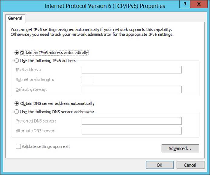
FIGURE 6-12 Manually configure an IPv6 address in Windows Server 2012 or Windows Server 2012 R2.
![]() By using the New-NetIPAddress and Set-DnsClientServerAddress cmdlets of Windows PowerShell
By using the New-NetIPAddress and Set-DnsClientServerAddress cmdlets of Windows PowerShell
![]() By using commands from the netsh interface ipv6 context of the Netsh.exe command-line utility
By using commands from the netsh interface ipv6 context of the Netsh.exe command-line utility
The following is an example of using Windows PowerShell to manually configure an IPv6 address on a physical interface of a computer running Windows Server 2012 or Windows Server 2012 R2. First, here is the output from running the Ipconfig command on the server:
PS C:\> ipconfig
Windows IP Configuration
Ethernet adapter Ethernet:
Connection-specific DNS Suffix . :
Link-local IPv6 Address . . . . . : fe80::2025:61fb:b68:c266%12
IPv4 Address. . . . . . . . . . . : 172.16.11.75
Subnet Mask . . . . . . . . . . . : 255.255.255.0
Default Gateway . . . . . . . . . : 172.16.11.1
Tunnel adapter isatap.{DD59BFFD-706A-4685-9073-647788046335}:
Media State . . . . . . . . . . . : Media disconnected
Connection-specific DNS Suffix . :
Tunnel adapter Teredo Tunneling Pseudo-Interface:
Media State . . . . . . . . . . . : Media disconnected
Connection-specific DNS Suffix . :
From the preceding command, you can see that the physical interface named Ethernet has two addresses assigned:
![]() The IPv4 address 172.16.11.75
The IPv4 address 172.16.11.75
![]() The link-local IPv6 address fe80::2025:61fb:b68:c266%12
The link-local IPv6 address fe80::2025:61fb:b68:c266%12
The %12 appended to the link-local address is called a zone identifier and is used to specify the link on which the address is located. On Windows platforms, the zone identifier is equal to the index of the interface, and you can use the Get-NetAdapter cmdlet to display a list of names and indexes of physical interfaces on computers running Windows Server 2012 or Windows Server 2012 R2 as follows:
PS C:\> Get-NetAdapter | fl Name,ifIndex
Name : Ethernet
ifIndex : 12
Instead of using the Ipconfig command, you can also use the Get-NetIPAddress cmdlet as follows to display the address information for the interface named Ethernet:
PS C:\> Get-NetIPAddress | where {$_.InterfaceAlias -eq "Ethernet"}
IPAddress : fe80::2025:61fb:b68:c266%12
InterfaceIndex : 12
InterfaceAlias : Ethernet
AddressFamily : IPv6
Type : Unicast
PrefixLength : 64
PrefixOrigin : WellKnown
SuffixOrigin : Link
AddressState : Preferred
ValidLifetime : Infinite ([TimeSpan]::MaxValue)
PreferredLifetime : Infinite ([TimeSpan]::MaxValue)
SkipAsSource : False
PolicyStore : ActiveStore
IPAddress : 172.16.11.75
InterfaceIndex : 12
InterfaceAlias : Ethernet
AddressFamily : IPv4
Type : Unicast
PrefixLength : 24
PrefixOrigin : Manual
SuffixOrigin : Manual
AddressState : Preferred
ValidLifetime : Infinite ([TimeSpan]::MaxValue)
PreferredLifetime : Infinite ([TimeSpan]::MaxValue)
SkipAsSource : False
PolicyStore : ActiveStore
Note how the preceding cmdlet output is more informative than the output from the Ipconfig command.
You can use the NewNetIPAddress cmdlet to assign a new global unicast IPv6 address with prefix length 64 and also a default gateway address to the Ethernet interface as follows:
PS C:\> New-NetIPAddress -InterfaceAlias "Ethernet" -IPAddress 2001:DB8:3FA9::D3:9C5A `
-PrefixLength 64 -DefaultGateway 2001:DB8:3FA9::0C01
IPAddress : 2001:db8:3fa9::d3:9c5a
InterfaceIndex : 12
InterfaceAlias : Ethernet
AddressFamily : IPv6
Type : Unicast
PrefixLength : 64
PrefixOrigin : Manual
SuffixOrigin : Manual
AddressState : Tentative
ValidLifetime : Infinite ([TimeSpan]::MaxValue)
PreferredLifetime : Infinite ([TimeSpan]::MaxValue)
SkipAsSource : False
PolicyStore : ActiveStore
IPAddress : 2001:db8:3fa9::d3:9c5a
InterfaceIndex : 12
InterfaceAlias : Ethernet
AddressFamily : IPv6
Type : Unicast
PrefixLength : 64
PrefixOrigin : Manual
SuffixOrigin : Manual
AddressState : Invalid
ValidLifetime : Infinite ([TimeSpan]::MaxValue)
PreferredLifetime : Infinite ([TimeSpan]::MaxValue)
SkipAsSource : False
PolicyStore : PersistentStore
To verify the result, you can use the Get-NetIPAddress cmdlet with the –AddressFamily parameter to display only IPv6 addressing information as follows:
PS C:\> Get-NetIPAddress -AddressFamily IPv6 | where {$_.InterfaceAlias -eq "Ethernet"}
IPAddress : fe80::2025:61fb:b68:c266%12
InterfaceIndex : 12
InterfaceAlias : Ethernet
AddressFamily : IPv6
Type : Unicast
PrefixLength : 64
PrefixOrigin : WellKnown
SuffixOrigin : Link
AddressState : Preferred
ValidLifetime : Infinite ([TimeSpan]::MaxValue)
PreferredLifetime : Infinite ([TimeSpan]::MaxValue)
SkipAsSource : False
PolicyStore : ActiveStore
IPAddress : 2001:db8:3fa9::d3:9c5a
InterfaceIndex : 12
InterfaceAlias : Ethernet
AddressFamily : IPv6
Type : Unicast
PrefixLength : 64
PrefixOrigin : Manual
SuffixOrigin : Manual
AddressState : Preferred
ValidLifetime : Infinite ([TimeSpan]::MaxValue)
PreferredLifetime : Infinite ([TimeSpan]::MaxValue)
SkipAsSource : False
PolicyStore : ActiveStore
The interface is now multihomed because it has one link-local IPv6 address and one global IPv6 address. Opening the Internet Protocol Version 6 (TCP/IPv6) Properties dialog box displays the expected manually configured address information, as shown in Figure 6-13.
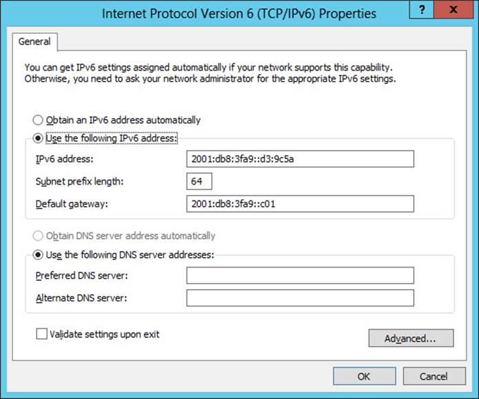
FIGURE 6-13 Verify IPv6 address settings configured using Windows PowerShell.
To configure preferred and alternate DNS servers for this interface, use the Set-DnsClientServerAddress cmdlet. For more information on Net TCP/IP and DNS client cmdlets, see the following TechNet Library pages:
![]() http://technet.microsoft.com/en-us/library/hh826123.aspx
http://technet.microsoft.com/en-us/library/hh826123.aspx
![]() http://technet.microsoft.com/en-us/library/jj590772.aspx
http://technet.microsoft.com/en-us/library/jj590772.aspx
Stateless address autoconfiguration
Stateless address autoconfiguration is one of the most valuable aspects of IPv6 because it enables IPv6 nodes to communicate on a network without the need to manually assign addresses to them or deploy a DHCP server. The automatic assignment of link-local addresses to interfaces on an IPv6 host is one example of stateless address autoconfiguration at work, and it enables hosts on the same link to communicate with one another. This type of address autoconfiguration is called stateless because it does not make use of an address configuration protocol such as DHCP.
Another example of stateless address configuration at work is when an IPv6 host uses router discovery to automatically configure additional addresses, such as global or unicast local addresses, a default gateway address, and other IPv6 configuration parameters. What typically happens is this:
1. The host (which here is a computer running Windows Server 2012 or Windows Server 2012 R2) sends out a Router Solicitation message to request a Router Advertisement message from any router listening on the host’s link.
2. A router (either an IPv6 router or an ISATAP router) on the host’s link responds to the host’s message by sending a Router Advertisement message to the host.
3. The host uses the information in the Router Advertisement message to assign a tentative address to the host along with any additional settings specified. IPv6 addresses that have been autoconfigured can be in any of the following states:
![]() Tentative The address still needs to be verified as unique by performing duplicate address detection. Tentative addresses cannot receive unicast traffic until they have been verified as valid.
Tentative The address still needs to be verified as unique by performing duplicate address detection. Tentative addresses cannot receive unicast traffic until they have been verified as valid.
![]() Valid The address is unique. A valid address is also either preferred or deprecated.
Valid The address is unique. A valid address is also either preferred or deprecated.
![]() Preferred The address is valid and therefore can be used for sending or receiving unicast traffic.
Preferred The address is valid and therefore can be used for sending or receiving unicast traffic.
![]() Deprecated The address is valid and therefore can be used for sending or receiving unicast traffic, but it should not be used to initiate any new communication.
Deprecated The address is valid and therefore can be used for sending or receiving unicast traffic, but it should not be used to initiate any new communication.
![]() Invalid The address can no longer be used for sending or receiving unicast traffic.
Invalid The address can no longer be used for sending or receiving unicast traffic.
4. The time during which an address is in a particular state is determined by information provided by the router.
Note: Address autoconfiguration is not for routers
Apart from configuring link-local addresses, address autoconfiguration is used only to assign addresses to hosts. Addresses for routers must be configured using a different method, such as manual address assignment.
Stateful address autoconfiguration
Stateful address autoconfiguration is based on the use of an address-resolution protocol. On IPv4 networks, DHCP is such a protocol and it can be used for dynamically assigning IP addresses and other configuration settings to interfaces on hosts. The infrastructure for DHCP consists of DHCP servers, DHCP clients, and DHCP relay agents that can relay DHCP messages between clients and servers on different subnets.
The IPv6 version of this protocol is called DHCPv6, and it uses a similar infrastructure of DHCPv6 servers, DHCPv6 clients, and DHCPv6 relay agents. However, DHCPv6 can provide IPv6 hosts with both stateful address configuration and stateless address configuration settings. This can be a problem because it can result in additional addresses being assigned to hosts, but you can prevent this by configuring your IPv6 routers appropriately so that hosts are assigned only stateful addresses by DHCPv6 servers.
One reason for deploying a DHCPv6 server on an IPv6 network is because Windows does not support stateless address autoconfiguration of DNS server settings using Router Advertisement messages. This means that a DHCPv6 server is required if your Windows computers need to be able to perform DNS name resolution using IPv6.
DHCPv6 client software is built into the following versions of Windows:
![]() Windows 8.1
Windows 8.1
![]() Windows 8
Windows 8
![]() Windows 7
Windows 7
![]() Windows Vista
Windows Vista
![]() Windows Server 2012 R2
Windows Server 2012 R2
![]() Windows Server 2012
Windows Server 2012
![]() Windows Server 2008 R2
Windows Server 2008 R2
![]() Windows Server 2008
Windows Server 2008
Configuring a DHCPv6 server
The DHCP Server service in the following versions of Windows Server supports both stateful and stateless address autoconfiguration through DHCPv6:
![]() Windows Server 2012 R2
Windows Server 2012 R2
![]() Windows Server 2012
Windows Server 2012
![]() Windows Server 2008 R2
Windows Server 2008 R2
![]() Windows Server 2008
Windows Server 2008
You can configure a computer running Windows Server 2012 or Windows Server 2012 R2 as either a DHCPv6 stateless server or a DHCPv6 stateful server by performing the following steps:
1. Begin by installing the DHCP Server role on your server.
2. Assign static IPv6 addresses to the DHCPv6 server interfaces that will be listening for incoming DHCPv6 request messages.
3. Open the DHCP snap-in and expand the IPv6 node beneath the server node.
4. To configure DHCPv6 options for stateless address autoconfiguration, right-click the Server Options node beneath the IPv6 node and select Configure Options as shown here:
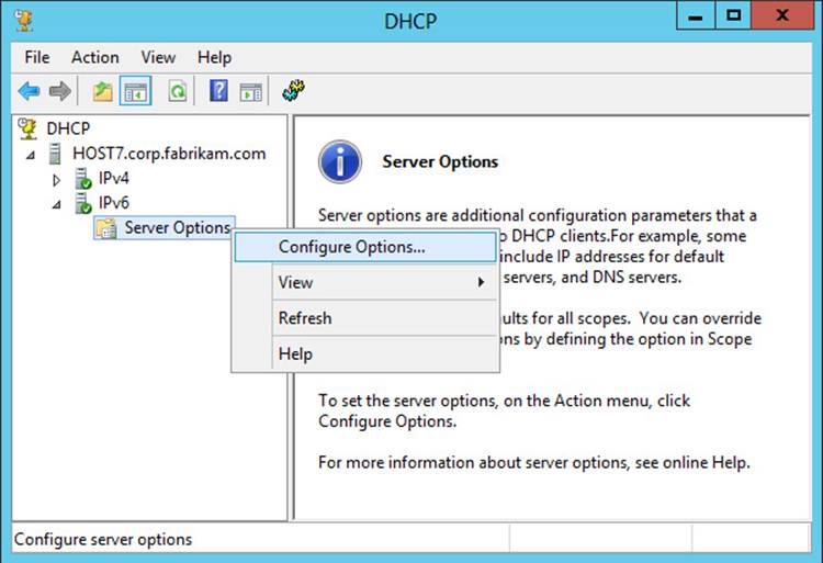
Then configure the DHCPv6 server options as desired. For example, you could configure option 23 DNS Recursive Name Server IPv6 Address List as shown here:
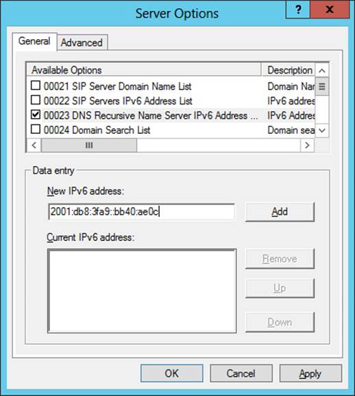
5. To configure DHCPv6 options for stateful address autoconfiguration, right-click the IPv6 node and select New Scope as shown here:
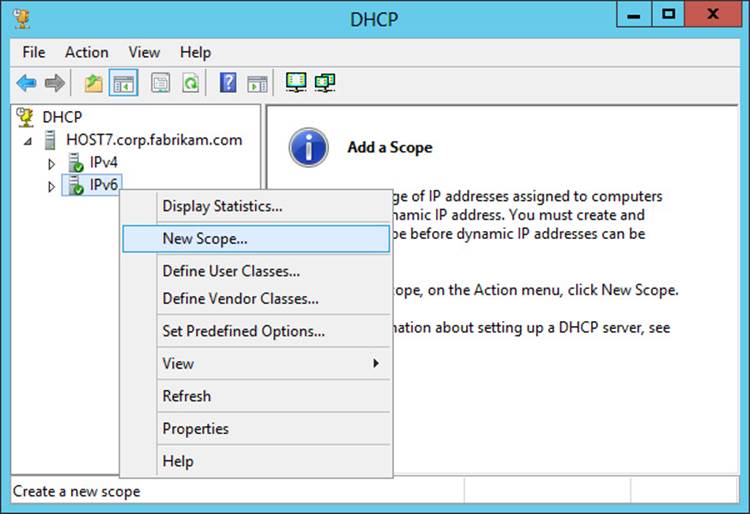
Then use the New Scope Wizard to specify a name and description for the scope, an IPv6 subnet prefix, and the other information required.
IPv6 transition technologies
The ultimate goal of IPv6 is for IPv4 to eventually be retired and all nodes on all TCP/IP networks to use only IPv6. However, such a goal might take years, or even decades, to achieve. In the meantime, IPv4 and IPv6 nodes must be able to interoperate on the same network so that communications will not be disrupted, and IPv6 transition technologies make this possible. Windows platforms can be used to implement the following IPv6 transition technologies:
![]() ISATAP This transition technology enables IPv6/IPv4 nodes on an IPv4-only intranet to use IPv6 to communicate with each other and across the IPv6 Internet.
ISATAP This transition technology enables IPv6/IPv4 nodes on an IPv4-only intranet to use IPv6 to communicate with each other and across the IPv6 Internet.
![]() 6to4 This transition technology provides automatic tunneling that enables IPv6/IPv4 hosts to establish IPv6 connectivity with each other across the IPv4 Internet. However, implementing 6to4 requires that the edge device (router) use a public IPv4 address.
6to4 This transition technology provides automatic tunneling that enables IPv6/IPv4 hosts to establish IPv6 connectivity with each other across the IPv4 Internet. However, implementing 6to4 requires that the edge device (router) use a public IPv4 address.
![]() Teredo This transition technology provides automatic tunneling that enables IPv6/IPv4 hosts to establish IPv6 connectivity with each other across the IPv4 Internet even when IPv4 network address translation (NAT) devices need to be traversed. Because of this capability, Teredo is more suitable than 6to4 for small office/home office (SOHO) environments that use NATs to hide their private IPv4 addresses from the Internet.
Teredo This transition technology provides automatic tunneling that enables IPv6/IPv4 hosts to establish IPv6 connectivity with each other across the IPv4 Internet even when IPv4 network address translation (NAT) devices need to be traversed. Because of this capability, Teredo is more suitable than 6to4 for small office/home office (SOHO) environments that use NATs to hide their private IPv4 addresses from the Internet.
In addition, Windows platforms support the following IPv6-to-IPv4 traffic translation technologies:
![]() NAT64 This technology is used to enable IPv6-only nodes to access IPv4-only hosts. The DirectAccess features of Windows Server 2012 and Windows Server 2012 R2 use NAT64 to enable DirectAccess clients (which act as IPv6-only nodes) to access hosts on an IPv4 corporate network.
NAT64 This technology is used to enable IPv6-only nodes to access IPv4-only hosts. The DirectAccess features of Windows Server 2012 and Windows Server 2012 R2 use NAT64 to enable DirectAccess clients (which act as IPv6-only nodes) to access hosts on an IPv4 corporate network.
![]() DNS64 This technology is used to map IPv6-only address record (AAAA) name queries to IPv4 address record (A) name queries. Using DNS64 with NAT64 enables IPv6 nodes to initiate communication with IPv4-only nodes with no changes to either node.
DNS64 This technology is used to map IPv6-only address record (AAAA) name queries to IPv4 address record (A) name queries. Using DNS64 with NAT64 enables IPv6 nodes to initiate communication with IPv4-only nodes with no changes to either node.
![]() PortProxy This technology enables IPv4/IPv6 TCP traffic to be proxied to IPv4/IPv6 TCP traffic at a different address. The technology is useful when nodes cannot communicate using either IPv4 or IPv6.
PortProxy This technology enables IPv4/IPv6 TCP traffic to be proxied to IPv4/IPv6 TCP traffic at a different address. The technology is useful when nodes cannot communicate using either IPv4 or IPv6.
The following section describes one of these transition technologies (ISATAP) in more detail.
ISATAP
ISATAP enables unicast communication between IPv6/IPv4 hosts across the IPv4-only Internet. ISATAP works by encapsulating IPv6 packets with an IPv4 header so that the IPv6 packet can be sent over an IPv4-only network. This approach is called IPv6-over-IPv4 tunneling, and ISATAP uses automatic tunneling that does not require any manual configuration.
ISATAP addresses
ISATAP addresses are assigned by ISATAP hosts to their ISATAP tunnel interfaces. An ISATAP address consists of a valid 64-bit unicast address prefix and a 64-bit interface identifier. The interface identify can be either ::0:5efe:w.x.y.z or ::200:5efe:w.x.y.z, where w.x.y.z is either a private or public IPv4 address, respectively.
On Windows platforms, IPv6 automatically creates a separate ISATAP tunneling interface for each LAN interface that has a unique DNS suffix. A link-local ISATAP address is then automatically configured on these ISATAP interfaces to enable IPv6 communication over an IPv4-only network without the need to assign global or unique local ISATAP addresses to the interfaces.
In Windows Server 2012 and Windows Server 2012 R2, you can use the Get-NetIPInterface cmdlet to list the interfaces on the computer (the command output has been truncated for display reasons):
PS C:\> Get-NetIPInterface -AddressFamily IPv6
ifIndex InterfaceAlias NlMtu(Bytes) InterfaceMetric ConnectionState
------- -------------- ------------ --------------- ---------------
12 Ethernet 1500 5 Connected
14 Teredo Tunneling Pseudo-Inte... 1280 50 Disconnected
13 isatap.{DD59BFFD-706A-4685-9... 1280 50 Disconnected
1 Loopback Pseudo-Interface 1 4294967295 50 Connected
From the preceding output, you can see that the index number of the ISATAP interface is 13, which allows you to display more detailed information about the interface as follows:
PS C:\> Get-NetIPInterface -AddressFamily IPv6 -ifIndex 13 | fl
InterfaceIndex : 13
InterfaceAlias : isatap.{DD59BFFD-706A-4685-9073-647788046335}
AddressFamily : IPv6
Forwarding : Disabled
Advertising : Disabled
NlMtu(Bytes) : 1280
AutomaticMetric : Enabled
InterfaceMetric : 50
NeighborDiscoverySupported : Yes
NeighborUnreachabilityDetection : Disabled
BaseReachableTime(ms) : 30000
ReachableTime(ms) : 23000
RetransmitTime(ms) : 1000
DadTransmits : 0
RouterDiscovery : Enabled
ManagedAddressConfiguration : Disabled
OtherStatefulConfiguration : Disabled
WeakHostSend : Disabled
WeakHostReceive : Disabled
IgnoreDefaultRoutes : Disabled
AdvertisedRouterLifetime : 00:30:00
AdvertiseDefaultRoute : Disabled
CurrentHopLimit : 0
ForceArpNdWolPattern : Disabled
DirectedMacWolPattern : Disabled
EcnMarking : AppDecide
Dhcp : Disabled
ConnectionState : Disconnected
PolicyStore : ActiveStore
ISATAP components
As shown in Figure 6-14, an ISATAP infrastructure includes the following components:
![]() ISATAP subnets An ISATAP subnet is a portion of an IPv4-only network on which ISATAP will be used for IPv6-over-IPv4 tunneling.
ISATAP subnets An ISATAP subnet is a portion of an IPv4-only network on which ISATAP will be used for IPv6-over-IPv4 tunneling.
![]() ISATAP hosts An ISATAP host has an ISATAP tunneling interface, which it can use to communicate with other ISATAP hosts on the same ISATAP subnet. Windows computers can function as ISATAP hosts using link-local, unique local, or global ISATAP addresses.
ISATAP hosts An ISATAP host has an ISATAP tunneling interface, which it can use to communicate with other ISATAP hosts on the same ISATAP subnet. Windows computers can function as ISATAP hosts using link-local, unique local, or global ISATAP addresses.
![]() ISATAP routers An ISATAP router is used to enable communication between ISATAP hosts on an ISATAP subnet and IPv6 hosts on an IPv6-capable network. Computers running Windows Server 2012 or Windows Server 2012 R2 can function as ISATAP routers by configuring their LAN interfaces with appropriate IPv6 addresses, routes, and other settings.
ISATAP routers An ISATAP router is used to enable communication between ISATAP hosts on an ISATAP subnet and IPv6 hosts on an IPv6-capable network. Computers running Windows Server 2012 or Windows Server 2012 R2 can function as ISATAP routers by configuring their LAN interfaces with appropriate IPv6 addresses, routes, and other settings.
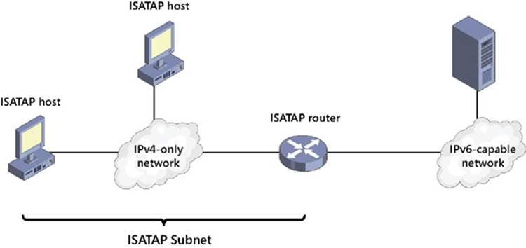
FIGURE 6-14 Review the components of an ISATAP deployment.
You can configure a Windows computer to use an ISATAP router in the following ways:
![]() By using Group Policy, as shown in Figure 6-15
By using Group Policy, as shown in Figure 6-15
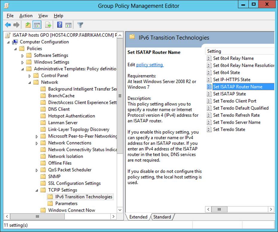
FIGURE 6-15 Configure a Windows computer to use an ISATAP router by using Group Policy settings.
![]() By using the Set-NetIsatapConfiguration cmdlet
By using the Set-NetIsatapConfiguration cmdlet
![]() By using the Netsh interface isatap set router command
By using the Netsh interface isatap set router command
Important: Scope of ISATAP deployment
Do not deploy ISATAP across your entire IPv4 network infrastructure. Instead, enable it only on select computers within your organization that need it.
Lesson summary
![]() Windows uses a dual IP layer TCP/IP stack that supports both IPv4 and IPv6 communications.
Windows uses a dual IP layer TCP/IP stack that supports both IPv4 and IPv6 communications.
![]() IPv6 is enabled by default and cannot be uninstalled, but you can selectively disable different types of IPv6 interfaces and capabilities by editing the registry.
IPv6 is enabled by default and cannot be uninstalled, but you can selectively disable different types of IPv6 interfaces and capabilities by editing the registry.
![]() IPv6 addresses can be unicast, multicast, or anycast. Unicast addresses include global, link-local, unique local, special, and transition addresses.
IPv6 addresses can be unicast, multicast, or anycast. Unicast addresses include global, link-local, unique local, special, and transition addresses.
![]() You can often determine the type of an IPv6 address by its prefix.
You can often determine the type of an IPv6 address by its prefix.
![]() You can assign IPv6 addresses manually or by using stateless or stateful address autoconfiguration.
You can assign IPv6 addresses manually or by using stateless or stateful address autoconfiguration.
![]() You can configure Windows Server 2012 and Windows Server 2012 R2 as a stateless or stateful DHCPv6 server.
You can configure Windows Server 2012 and Windows Server 2012 R2 as a stateless or stateful DHCPv6 server.
![]() Windows includes several IPv6 transition technologies, including ISATAP, 6to4, and Teredo. Windows also includes several traffic translation technologies, including NAT64, DNS64, and PortProxy.
Windows includes several IPv6 transition technologies, including ISATAP, 6to4, and Teredo. Windows also includes several traffic translation technologies, including NAT64, DNS64, and PortProxy.
![]() The components of an ISATAP deployment include ISATAP subnets, ISATAP hosts, and ISATAP routers. Windows computers can be ISATAP hosts, and Windows Server 2012 and Windows Server 2012 R2 can be configured as an ISATAP router.
The components of an ISATAP deployment include ISATAP subnets, ISATAP hosts, and ISATAP routers. Windows computers can be ISATAP hosts, and Windows Server 2012 and Windows Server 2012 R2 can be configured as an ISATAP router.
Lesson review
Answer the following questions to test your knowledge of the information in this lesson. You can find the answers to these questions and explanations of why each answer choice is correct or incorrect in the “Answers” section at the end of this chapter.
1. Which of the following is not true about IPv6 on Windows Server 2012 and Windows Server 2012 R2?
A. Windows Server 2012 and Windows Server 2012 R2 have a dual IP layer TCP/IP stack that supports both IPv4 and IPv6.
B. You can disable IPv6 on all interfaces by editing the registry on a Windows Server 2012 or Windows Server 2012 R2 computer.
C. You can use Windows Server 2012 and Windows Server 2012 R2 as a DHCPv6 server for stateless address autoconfiguration.
D. You can use Windows Server 2012 and Windows Server 2012 R2 as an ISATAP router.
2. The IPv6 address assigned to an interface has a prefix identifier of FE80::/64. What type of address is it?
A. Global address
B. Unique local address
C. Link-local address
D. Multicast address
3. Which Windows PowerShell cmdlet can you use to display the address information for an interface?
A. Ipconfig
B. Get-NetAdapter
C. Get-NetIPAddress
D. Get-NetIPInterface
4. What do you need to do or use for Windows computers on an IPv4-only network to be able to communicate with Windows computers on a different network that is IPv6-capable?
A. You need to do nothing because Windows computers automatically assign IPv6 addresses to their LAN interfaces using stateless address autoconfiguration.
B. You need to deploy Windows Server 2012 or Windows Server 2012 R2 as an ISATAP router and use it to forward traffic between the IPv4-only and IPv6-capable networks.
C. You need to deploy Windows Server 2012 or Windows Server 2012 R2 as a Teredo server and use it to forward traffic between the IPv4-only and IPv6-capable networks.
D. You need to deploy Windows Server 2012 or Windows Server 2012 R2 as a DHCPv6 server and use it to assign global IPv6 addresses to the computers on the IPv4-only network.
Practice exercises
The goal of this section is to provide you with hands-on practice with the following:
![]() Implementing DHCP failover using Windows PowerShell
Implementing DHCP failover using Windows PowerShell
![]() Configuring a caching-only DNS server using Windows PowerShell
Configuring a caching-only DNS server using Windows PowerShell
To perform the following exercises, you need at least two installations of Windows Server 2012 R2 that were deployed using the Server With A GUI installation option. The first server should be the first domain controller in the forest root domain corp.contoso.com and should have the DNS Server role installed and configured in the default manner using Active Directory–integrated zones. The second server should be a member server in the contoso.com domain and have no server roles installed. Both servers should have static IP addresses assigned and have Internet connectivity. You should be logged on interactively to each server using a user account that is a member of the Domain Admins group.
You also need one workstation running Windows Vista, Windows 7, Windows 8 or Windows 8.1. The workstation should be a stand-alone computer that belongs to a workgroup. The workstation should have its IP address assigned dynamically using DHCP or Automatic Private IP Addressing (APIPA). You should be logged on interactively to the workstation using a user account that is a member of local Administrators group on the computer. The workstation should be turned off until you are instructed to turn it on.
For the purposes of these exercises, the name of the first server is assumed to be SERVER1, the second server is SERVER2, and the workstation is CLIENT1. In addition, the IP addresses of SERVER1 and SERVER 2 are assumed to be 10.10.0.1 and 10.10.0.2, respectively. If your computers or domains are named differently or if you have different IP addresses assigned to your servers, you should modify the steps in these exercises accordingly.
Exercise 1: Implementing DHCP failover using Windows PowerShell
In this exercise, you ensure DHCP availability for clients in the corp.contoso.com domain by using Windows PowerShell to install the DHCP Server role on both servers, create a scope on SERVER1, and configure and verify DHCP failover.
1. Log on to SERVER1, open Server Manager, select the All Servers page, and make sure that both servers are displayed in the Servers tile. If SERVER2 is not displayed, add it to the server pool.
2. Open a Windows PowerShell prompt and run the following command to install the DHCP Server role on both servers:
Invoke-Command -ComputerName SERVER1,SERVER2 -ScriptBlock `
{Install-WindowsFeature -Name DHCP -IncludeManagementTools -Restart}
Note that although you specified the –Restart parameter, the servers did not restart after role installation because a restart was determined to be unnecessary.
3. Authorize both DHCP servers in Active Directory by executing the following commands:
Add-DhcpServerInDC -DnsName SERVER1
Add-DhcpServerInDC -DnsName SERVER2
4. Use the Get-DhcpServerInDC cmdlet to verify that the servers have been authorized in Active Directory.
5. Create a new scope on SERVER1 and activate the scope by running the following command:
Add-DhcpServerv4Scope -ComputerName SERVER1 -StartRange 10.10.0.50 `
-EndRange 10.10.0.100 -Name "corp clients" -SubnetMask 255.255.0.0 -State Active
6. Use the Get-DhcpServerv4Scope cmdlet to verify that the new scope has been created on SERVER1 and is active.
7. Use Get-DhcpServerv4Scope –ComputerName SERVER2 to verify that SERVER 2 currently has no scopes on it.
8. Run the following command to create a DHCP failover relationship in load-balance mode between the two servers with SERVER 2 as the partner server and failover implemented for the newly created scope:
Add-DhcpServerv4Failover -Name "SERVER1 to SERVER2" -ScopeId 10.10.0.0 `
-PartnerServer SERVER2 -ComputerName SERVER1 -LoadBalancePercent 50 `
-AutoStateTransition $true
9. Use the Get-DhcpServerv4Failover cmdlet to view the properties of the new failover relationship.
10. Use Get-DhcpServerv4Scope –ComputerName SERVER2 to verify that the scope has been replicated from SERVER1 to SERVER2.
11. Turn on CLIENT1 and log on to the client computer.
12. Open a command prompt and use the ipconfig command to view the current IP address of the computer. If the client computer is currently using an address in the APIPA range (169.254.x.y), use ipconfig /renew to acquire an address from a DHCP server on your network. Verify that the address acquired comes from the scope you created earlier.
13. Verify that the client computer’s address is recorded as leased in the DHCP database of SERVER1 by executing the following command:
Get-DhcpServerv4Lease -ComputerName SERVER1 -ScopeId 10.10.0.0
14. Verify that the client computer’s address is recorded as leased in the DHCP database of SERVER2 by executing the following command:
Get-DhcpServerv4Lease -ComputerName SERVER2 -ScopeId 10.10.0.0
Exercise 2: Configuring a caching-only DNS server using Windows PowerShell
In this exercise, you configure a caching-only DNS server using Windows PowerShell. You then configure a forwarder on your caching-only DNS server to improve its name-resolution performance.
1. Log on to SERVER1, open Server Manager, select the All Servers page, and make sure that both servers are displayed in the Servers tile. If SERVER2 is not displayed, add it to the server pool.
2. Open a Windows PowerShell prompt and run the following command to install the DNS Server role on SERVER2:
Install-WindowsFeature -Name DNS -ComputerName SERVER2 -IncludeManagementTools
-Restart
Note that although you specified the –Restart parameter, the servers did not restart after role installation because a restart was determined to be unnecessary.
3. SERVER2 is now configured as a caching-only DNS server. It is not authoritative for any domains and can only perform queries, cache the answers, and return the results. Caching-only DNS servers can be useful at locations such as branch-office sites and use root hints to identify the authoritative DNS servers for the root zone of your organization’s DNS namespace.
4. SERVER2 is currently using root hints for recursively performing name resolution. To view the root hints configured on SERVER2, run the following command:
Get-DnsServerRootHint -ComputerName SERVER2
5. Display the contents of the DNS server cache on SERVER2 by running the following command:
Show-DnsServerCache -ComputerName SERVER2
6. Use the nslookup command-line utility to attempt to use SERVER2 for resolving the IP address for the fully qualified domain name (FQDN) www.bing.com as follows:
nslookup www.bing.com SERVER2
7. Note that one or more DNS server timeouts might occur when you perform this name query. This is because name resolution is being performed recursively, beginning with the root name servers on the Internet, which can take several seconds to complete. If no response is received to your query, repeat running the preceding command until a nonauthoritative response is received.
8. Use the command Show-DnsServerCache –ComputerName SERVER2 and note that the DNS server cache now contains numerous entries relating to the name query you performed using nslookup.
9. Clear the DNS server cache on SERVER2 by running the following command:
Clear-DnsServerCache -ComputerName SERVER2
10. Display the contents of the DNS server cache on SERVER2 again by running this command:
Show-DnsServerCache -ComputerName SERVER2
11. Note that the cache entries relating to the name query you performed using nslookup have now been deleted. The only entries that remain in the cache are those for the root hints configured on the server.
12. To speed up name resolution on your caching-only name server, configure SERVER1 as a forwarder on SERVER2. After you do this, any name query sent to SERVER2 will be forwarded to SERVER1, which will then use its external forwarders at your Internet Service Provider (ISP) for resolving the query.
13. Configure SERVER1 as a forwarder on SERVER2 by running the following command:
Add-DnsServerForwarder -IPAddress 10.10.0.1 -ComputerName SERVER2
14. Verify the result by displaying the forwarders configured on SERVER2 as follows:
Get-DnsServerForwarder -ComputerName SERVER2
15. Use nslookup to perform another name query against SERVER2 for the FQDN www.bing.com. The response should be received almost immediately, with no DNS server timeouts occurring. This is because the query was forwarded to SERVER1, which then forwarded it to your ISP’s DNS servers for resolution. This approach is generally much faster than using the Internet root name servers to recursively resolve the requested FQDN.
16. Display the contents of the DNS server cache on SERVER2 again. Note the cache entries relating to your name query and note also that there are considerably fewer cache entries than when root hints alone were used for performing recursive name resolution.
Suggested practice exercises
The following additional practice exercises are designed to give you more opportunities to practice what you learned and to help you successfully master the lessons presented in this chapter.
![]() Exercise 1 Modify the steps in the Exercise 2 so that when a client computer at the branch office issues a name query to the caching-only DNS server located at that branch office, the following happens:
Exercise 1 Modify the steps in the Exercise 2 so that when a client computer at the branch office issues a name query to the caching-only DNS server located at that branch office, the following happens:
![]() If the queried FQDN is for something on the corporate intranet, the query is forwarded to the DNS server located at the central office.
If the queried FQDN is for something on the corporate intranet, the query is forwarded to the DNS server located at the central office.
![]() If the queried FQDN is for something on the Internet, the query is forwarded to the DNS servers at the organization’s ISP.
If the queried FQDN is for something on the Internet, the query is forwarded to the DNS servers at the organization’s ISP.
Hint: You need to use conditional forwarding. See http://technet.microsoft.com/en-us/library/cc794735(v=WS.10).aspx for more information.
![]() Exercise 2 Create a Windows PowerShell script that runs a series of commands that removes the static IP address, subnet mask, default gateway, and DNS server settings from the network adapter of a server and then assigns a different static IP address, subnet mask, default gateway, and DNS server settings to the adapter.
Exercise 2 Create a Windows PowerShell script that runs a series of commands that removes the static IP address, subnet mask, default gateway, and DNS server settings from the network adapter of a server and then assigns a different static IP address, subnet mask, default gateway, and DNS server settings to the adapter.
![]() Exercise 3 Create a Windows PowerShell script that runs a series of commands that assigns static IP addresses to two network adapters on a server and then adds static routes to the router table to enable the server to be used as a router to join two subnets.
Exercise 3 Create a Windows PowerShell script that runs a series of commands that assigns static IP addresses to two network adapters on a server and then adds static routes to the router table to enable the server to be used as a router to join two subnets.
Answers
This section contains the answers to the lesson review questions in this chapter.
Lesson 1
1. Correct answer: B
A. Incorrect: The server-cluster approach involves using the Failover Clustering feature of Windows Server 2008 or Windows Server 2008 R2 to cluster DHCP servers so that if the primary DHCP server in a cluster fails, the secondary server can take up the slack and continue leasing addresses to clients.
B. Correct: The split-scope approach involves splitting the IP address pool of a scope between two DHCP servers, typically by assigning the primary server 80 percent of the addresses in the scope and the secondary server the remaining 20 percent of the addresses. That way, if the primary server goes offline for any reason, DHCP clients on the subnet can still respond to lease renewal requests from the secondary server.
C. Incorrect: The standby-server approach uses a hot-standby DHCP server with scopes and options configured identically to your production DHCP server.
D. Incorrect: The DHCP-failover approach involves configuring two DHCP servers to provide leases from the same pool of addresses. The two servers then replicate lease information between them, which enables one server to assume responsibility for providing leases to all clients on the subnet when the other server is unavailable.
2. Correct answers: A and C
A. Correct: DHCP failover only supports using a maximum of two DHCP servers.
B. Incorrect: DHCP failover relationships are limited to IPv4 scopes and subnets.
C. Correct: DHCP failover can be implemented in two ways: using load-balance mode or hot-standby mode. In load-balance mode, leases are issued from both servers equally, which ensures availability and provides load balancing for your DHCP services. In hot-standby mode, leases are issued from the primary server until it fails, whereupon the lease data is automatically replicated to the secondary server, which assumes the load.
D. Incorrect: If the DHCP servers for which you want to implement DHCP failover are domain members, they must be authorized in Active Directory. However, you can also implement DHCP failover on stand-alone DHCP servers in a workgroup.
3. Correct answers: A, B, and C
A. Correct: One scenario in which you might implement hot-standby mode is for organizations that have a central hub site (typically the data center at the head office) connected via WAN links to multiple remote branch-office sites.
B. Correct: A common implementation of hot-standby mode is when each branch-office DHCP server has a failover relationship with the central-office DHCP server, with the branch office assuming the role as primary and the central server as secondary. That way, if a DHCP server fails at a branch office, the central server can take up the slack for the remote site.
C. Correct: Budget should not be a consideration when implementing hot-standby mode because you can use the existing DHCP server in your data center as the standby for DHCP servers in your branch offices. In other words, no new servers need to be deployed if you want to implement DHCP failover in hot-standby mode.
D. Incorrect: DHCP failover in load-balance mode is a more appropriate solution for organizations that have only one physical site.
Lesson 2
1. Correct answer: D
A. Incorrect: DNSKEY resource records contain the public keys for a particular zone. Other types of DNSSEC resource records include RRSIG, DS, and NSEC (or NSEC3).
B. Incorrect: Only zones that are authoritative can be signed. Zones that are not authoritative cannot be signed.
C. Incorrect: The KSK is an authentication key with a length of 2048 bits that is generated using the RSA/SHA-256 cryptographic algorithm. The KSK is used to sign all of the DNSKEY records at the root of the zone, and it is part of the chain of trust. By default, the KSK has a rollover frequency of 755 days and any DNSKEY records signed using the key have a signature validity of 168 hours.
D. Correct: When zone data is updated by a client sending a DNS dynamic update to an authoritative DNS server, that DNS server updates its own copy of the zone and generates the required signatures. The unsigned update is then securely replicated to all other authoritative servers, and each DNS server adds the update to its copy of the zone and generates the required signatures.
2. Correct answer: C
A. Incorrect: When an authoritative server receives the recursive query, it returns an authoritative response to the client’s local server.
B. Incorrect: When an authoritative server receives the recursive query, it returns an authoritative response to the client’s local server.
C. Correct: The local server uses the public key of the signed zone on the authoritative server to validate the response it received from the authoritative server.
D. Incorrect: The DNS client on all supported versions of Microsoft Windows is DNSSEC-aware but nonvalidating.
3. Correct answer: C
A. Incorrect: You should begin by introducing Windows Server 2012 or Windows Server 2012 R2 domain controllers into your environment. These domain controllers should also have the DNS Server role installed and be configured to use Active Directory–integrated zones.
B. Incorrect: After deciding which DNS zone to implement DNSSEC on, sign the zone by opening the DNS Manager console, selecting the DNS server, right-clicking the zone, selecting DNSSEC, and then selecting Sign The Zone.
C. Correct: If the zone you signed is an Active Directory–integrated zone, private zone-signing keys now replicate automatically to all domain controllers hosting the zone through Active Directory replication. Each zone owner signs its own copy of the zone when it receives the key as long as the zone owner is a domain controller running Windows Server 2012 or Windows Server 2012 R2.
D. Incorrect: The final step in deploying DNSSEC is to ensure security between the nonvalidating DNS client and its local DNS servers. The recommended way to do this is to use IPsec to protect the last mile between the client and its local DNS server. The DNS clients must also be configured to check that responses have been validated by their local DNS server, and you do this by configuring the Name Resolution Policy Table (NRPT) on the clients. The NRPT can be configured by using either Group Policy or Windows PowerShell.
Lesson 3
1. Correct answer: B
A. Incorrect: Parameters that are marked with an asterisk (*) are mandatory; those not marked this way are optional.
B. Correct: Parameters that are marked with an asterisk (*) are mandatory; those not marked this way are optional.
C. Incorrect: All parameters that Show-Command displays in the properties page for a cmdlet apply to that cmdlet.
D. Incorrect: All parameters that Show-Command displays in the properties page for a cmdlet can have values specified for them on that properties page.
2. Correct answer: C
A. Incorrect: You can use the Get-NetAdapterBinding cmdlet to display the bindings for the specified interface.
B. Incorrect: There is no cmdlet called Remove-NetAdapterBinding.
C. Correct: You can use the Disable-NetAdapterBinding cmdlet to disable the specified binding.
D. Incorrect: You can use the Disable-NetAdapter cmdlet to disable the specified network adapter.
3. Correct answer: B
A. Incorrect: If the –ScopeId parameter is used with this cmdlet, the result is to configure a scope option, not a server option.
B. Correct: This command configures a DHCP scope option that assigns the address 10.10.0.1 as the default gateway on any DHCP client whose IPv4 address is on the 10.10.20.0 subnet.
C. Incorrect: DHCP is not used to assign TCP/IP settings to routers.
D. Incorrect: DHCP is not used to assign TCP/IP settings to routers.
Lesson 4
1. Correct answer: B
A. Incorrect: A dual-layer TCP/IP stack has been a standard feature on Windows platforms since Windows Vista and Windows Server 2008.
B. Correct: You can disable IPv6 on most interfaces by editing the registry, but you cannot disable the loopback interface (::1) on a Windows computer.
C. Incorrect: The DHCP role can be configured for both stateless and stateful DHCPv6 address autoconfiguration.
D. Incorrect: Windows Server 2012 and Windows Server 2012 R2 computers can function as ISATAP routers by configuring their LAN interfaces with appropriate IPv6 addresses, routes, and other settings.
2. Correct answer: C
A. Incorrect: The first 3 bits of a global address are always 001 in binary format. This means that the first byte of the address can be 0x2 (binary 0010) or 0x3 (binary 0011) in hexadecimal format.
B. Incorrect: The first 8 bits of a unique local address are always 11111101 in binary format. This means that a unique local address always begins with FD and has a prefix identifier of FD00::/8.
C. Correct: The first 64 bits of a link-local address are always 11111110 10000000 00000000 00000000 in binary format. This means that a link-local address always begins with FE80 and has a prefix identifier of FE80::/64.
D. Incorrect: A multicast address always begins with 11111111 or FF.
3. Correct answer: C
A. Incorrect: You can use Ipconfig to display the address information for an interface, but it is not a Windows PowerShell cmdlet.
B. Incorrect: You can use Get-NetAdapter to get the basic network adapter properties.
C. Correct: You can use Get-NetIPAddress to get information about IP address configuration.
D. Incorrect: You can use Get-NetIPInterface to get information about the IP interface properties.
4. Correct answer: B
A. Incorrect: Windows computers automatically assign IPv6 addresses to their LAN interfaces using stateless address autoconfiguration, but these addresses are link-local addresses that can be used only for communications between computers on the same link.
B. Correct: An ISATAP router is used to enable communication between ISATAP hosts on an ISATAP subnet and IPv6 hosts on an IPv6-capable network. Computers running Windows Server 2012 or Windows Server 2012 R2 can function as ISATAP routers by configuring their LAN interfaces with appropriate IPv6 addresses, routes, and other settings.
C. Incorrect: Teredo is an IPv6 transition technology that provides automatic tunneling that enables IPv6/IPv4 hosts to establish IPv6 connectivity with each other across the IPv4 Internet even when IPv4 network address translation (NAT) devices need to be traversed.
D. Incorrect: Using a DHCPv6 server to assign IPv6 addresses to computers on an IPv4-only network will not help them communicate with computers on a different network that is IPv6-capable.