Mastering System Center 2012 R2 Configuration Manager (2014)
Chapter 10. Operating System Deployment
Most IT administrators want to automate as many functions as possible in order to reproduce the same outcome consistently and quickly to as many devices as possible, and setting up a basic computer build is no exception.
In Configuration Manager 2007 the operating system deployment (OSD) feature became one of the most important features of Configuration Manager. With Configuration Manager 2012 you can install Windows operating systems without any user intervention. We call this Zero-Touch deployment. When a Windows deployment is finished, the user is able to log into the network and start working with the new operating systems and the available applications. The operating system deployment feature is highly dependent on the Windows Assessment and Deployment Kit (ADK) for Windows 8.1. The Windows ADK is a prerequisite of Configuration Manager 2012 R2.
In Configuration Manager 2012 the operating system deployment feature matured with added features such as offline servicing. We will walk you through several Windows deployment scenarios without and with the use of the Microsoft Deployment Toolkit 2013.
In this chapter, you will learn to
· Specify a Network Access account
· Enable PXE support
· Update the driver catalog package
· Update an image from the console
What’s New in Operating System Deployment
The operating system deployment feature in Configuration Manager 2012 was not significantly changed from Configuration Manager 2007. Nevertheless some parts are enhanced, changed, or new to the feature. The following list shows the changes since Configuration Manager 2007:
· The Preboot Execution Environment (PXE) role was moved from the primary site server to the distribution point. This way scalability is increased since it is easier to deploy an extra distribution point.
· Updating a WIM image with the latest approved software updates is done from the Configuration Manager console.
· You can use task sequence media to deploy operating systems anywhere in your Configuration Manager hierarchy.
· A boot image is available throughout the Configuration Manager hierarchy instead of needing to deploy a boot image in every site.
· The Create Task Sequence Media Wizard provides the option to add prestart command files to prestage media, stand-alone media, and bootable media.
· You can configure the task sequence media to become unattended installation media by suppressing the Configuration Manager Boot Media Wizard during the installation.
· In the task sequence, a capture user state task or restore user state task supports the new features of the User State Migration Tool (USMT) version 4.
· From the task sequence you can install applications from the new application model.
· Configuration Manager 2012 supports deploying Windows To-Go devices.
· Configuration Manager 2012 supports deploying and uploading virtual hard disks to System Center 2012 R2 Virtual Machine Manager (VMM).
Planning for OSD with Configuration Manager 2012
Before you configure the feature, you should plan your operating system deployment, since you can deploy different kinds of operating systems in numerous ways. To deploy your operating systems in an effective and cost-efficient way, you need to address the following items when planning your operating system deployment:
· Deployment scenarios
· The kind of images to deploy
· The kind of components to use
Deployment Scenarios
You can deploy the operating system in different ways. In Configuration Manager 2012 you can deploy an operating system in two kinds of scenarios:
1. Bare-Metal Scenario Installing an operating system to a new out-of-the-box client computer
2. Refresh Computer Scenario Deploying an image to an existing Windows installation to perform an upgrade or reinstall while migrating the user state to the new Windows installation
The Kind of Images to Deploy
Configuration Manager 2012 supports, as did the previous version of Configuration Manager, the deployment of two kinds of operating system installations. You can install images, based on the Windows Imaging (WIM) format, or just install operating systems by using the source of an operating system installation. Using the source of an operating system is an unattended installation and is normally used to create a WIM image with a build-and-capture task sequence. The source can be a copy of the DVD of Windows 8.x, Windows 7, Windows Vista, Windows XP SP3, Windows Server 2003, Windows Server 2008 (R2), or Windows Server 2012 (R2).
1. Operating System Images Operating images are often custom images that are built with the build-and-capture task sequence. This task sequence allows you to install and create an image of a customized reference operating system image. Also, the operating system images are used when you want to build and capture a custom image of a Windows 7 or higher or a Windows Server 2008 or higher operating system.
2. Operating System Installer An installer source is used as the source for a build and capture to perform an unattended installation of legacy operating systems like Windows XP and Windows Server 2003 before capturing it to a WIM image.
Operating System Deployment Components
The operating system deployment feature uses different kinds of components within Configuration Manager 2012. We’ll look at each of them.
Boot Images
Configuration Manager 2012 comes with two default boot images. These images are available for all sites in the hierarchy. There is no need to create and deploy boot images for each Configuration Manager site in the hierarchy.
When you access a standard boot image, you can configure several settings in various tabs. To access the boot image, browse to the Software Library workspace ⇒ Overview ⇒ Operating Systems ⇒ Boot Images. The tabs shown in Figure 10.1 are available.
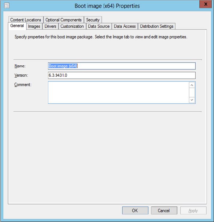
Figure 10.1 Boot Image Properties
1. General Tab In the General tab, you can enter or change the name, version, or comments of the boot image that’s already available in Configuration Manager 2012.
2. Images Tab The Images tab provides information about the boot image. If you changed the image properties with an external tool, you can reload the original properties.
3. Drivers Tab The Drivers tab provides an overview of the drivers that are injected into the boot image. You can also add drivers from the driver store to the boot image. Common drivers to add to boot images are network and SATA/SCSI drivers and any other critical drivers.
4. Customization Tab If you want to customize the selected boot image, you can find some options on the Customization tab. When you’re in the plan and build phases of your project and you want to test the deployment of images, you can enable command support in the Windows Preinstallation Environment (WinPE) phase of your deployment. Pressing F8 opens a command prompt that allows you to access the file system and log files that are located in the _SMSTaskSequence\Logs\Smstslog directory. There is also an option to change the background that is shown during the WinPE phase.
5. If you want to add a prestart command hook and supporting files, you can add the command line here.
6. Data Source Tab The Data Source tab supplies the path to the boot WIM image that is used for the boot image package. The Data Source tab is also the place to enable or disable the ability to boot the image from PXE.
7. Data Access Tab With settings in the Data Access tab you can configure how the package is stored on the distribution points.
8. Distribution Settings Tab Here you can define how the boot image package is distributed to the distribution points and set the priority.
9. Content Locations Tab On the Content Locations tab you can see on which distribution points or distribution point groups the image package is available. Selecting a distribution point or distribution point group allows you to validate the copy on the location, redistribute the boot image package to the location, or remove the boot image package from the location.
10.Optional Components Tab In earlier versions you would definitely create new boot images with the Microsoft Deployment Toolkit to be able to use advanced features within WinPE. Configuration Manager 2012 R2 adds the ability to add optional components to the WinPE images from the Configuration Manager console.
11.Security Tab The Security tab shows you the users who have administrative permissions to the boot image object.
Deciding When to Use Which Boot Image
There are two different versions of boot images to support two kinds of platforms, namely an x86 version and an x64 version.
You can use the x86 boot image version to deploy the following:
· 32-bit operating system image
· 64-bit operating system image
· 32-bit operating system install package
You can use the x64 boot image version to deploy the following:
· 64-bit operating system image
· 64-bit operating system install package
You can define per task sequence which boot image to use.
State Migration Point
The state migration point stores the user data that is gathered by USMT when a computer is being refreshed by a new Windows operating system. The component can be configured to store user data on different storage folders, depending on the deletion policy.
Distribution Points
The distribution point is used to store the content that is related to the operating system deployment. But in Configuration Manager 2012 two very important features have been moved to the distribution point, namely PXE and multicast.
When configuring a distribution point for operating system deployment, you can adjust the following settings:
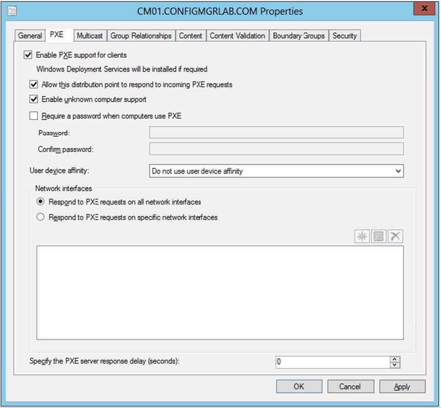
1. PXE Tab As mentioned earlier, the PXE feature has been moved to the distribution point. The PXE tab allows you to enable or disable support for PXE, but a Windows Deployment Services service must be present. As in earlier versions, you can configure PXE to respond to incoming PXE requests and unknown computer support. New is the ability to enable Primary User Assignment, which is discussed later in this chapter. If you want to secure PXE with a password, you can configure one. When you enable a boot image for PXE and the boot image is available on the distribution point, the boot image is also copied into the RemoteInstall\SMSBoot folder of Windows Deployment Services. Enabling the PXE feature will also install the Windows Deployment Services feature if the feature is not yet available.
2. Multicast Tab The Multicast feature has also been moved to the distribution point via PXE. You configure the options per distribution point.
Operating System Images
The operating system images are the WIM images that can be deployed to workstations or servers. An operating system image can be a captured operating system. When you access an operating system image, you can configure several settings in various tabs. To access an operating system image, go to the Software Library workspace ⇒ Overview ⇒ Operating Systems ⇒ Operating System Image.
1. General Tab The General Tab is used to supply information about the operating system image, like name, version, and comments.
2. Images The Images tab gives you information about the WIM image. Information like OS version, architecture, creation date, and more is shared. If you changed the image properties using an external tool, you can reload the information from the WIM image.
3. Data Source Tab The Data Source tab supplies the UNC path to the WIM image that is used for the operating system image package.
4. Data Access Tab With settings in the Data Access tab you can configure how the package is stored on the distribution points.
5. Distribution Settings Tab Here you can define how the operating system image package is distributed to the distribution points and set the priority. You are also able to define to allow this operating system image to be transferred via multicast via WinPE.
6. Servicing In the Servicing tab you are able to see or change the offline servicing schedule if offline servicing for an image is scheduled.
7. Installed Updates The installed updates tab gives you a list with installed updates that have been installed with offline servicing.
8. Content Locations Tab On the Content Locations tab you can see on which distribution points or distribution point groups the operating system image package is available. Selecting a distribution point or distribution point group allows you to validate the copy on the location, redistribute the operating system image package to the location, or remove the operating system image package from the location.
9. Security Tab The Security tab shows you the users who have administrative permissions to the operating system image object.
Operating System Installers
The operating system installers are the install source of an operating system. With the operating system installers you are able to install operating systems unattended. Operating system installers are used, for instance, while building and capturing an operating system image. When you access an operating system installer, you can configure several settings in various tabs. To access an operating system installer package, go to the Software Library workspace ⇒ Overview ⇒ Operating Systems ⇒ Operating System Installers. Operating system installers for Configuration Manager 2012 R2 are supported only for Windows 8.x. For earlier versions of Windows, you need to add custom boot images based on the Windows Automated Installation Kit.
1. General Tab The General Tab is used to supply information about the operating system installer, like name, version, and comments.
2. Editions The Editions tab allows you to see information about the selected edition in the installation source. For instance, a Windows Server 2008 R2 install source has more editions available; editions can be Standard, Enterprise, or Datacenter.
3. Data Source Tab The Data Source tab supplies the UNC path to the install source of the operating system installer that is used for the operating system installer package.
4. Data Access Tab With settings in the Data Access tab you can configure how the package is stored on the distribution points.
5. Distribution Settings Tab Here you can define how the operating system installer package is distributed to the distribution points and set the priority.
6. Content Locations Tab On the Content Locations tab you can see on which distribution points or distribution point groups the operating system installer package is available. Selecting a distribution point or distribution point group allows you to validate the copy on the location, redistribute the operating system installer package to the location, or remove the operating system installer package from the location.
7. Security Tab The Security tab shows you the users who have administrative permissions to the operating system installer object.
Task Sequences
Task sequences provide a mechanism to perform a series of tasks on a client computer without any user intervention. Using task sequences, you can deploy operating systems but also distribute software, configure client settings, update drivers, edit user states, and perform other tasks in support of operating system deployment. Task sequences are global data and are available for all Configuration Manager sites in the hierarchy.
With Configuration Manager 2012, you can create four different kinds of task sequences:
1. Install An Existing Image Package This task sequence will install an existing WIM image to a computer via the normal distribution method or PXE. This option uses a predefined sequence of steps. The steps will take care of wiping or formatting the disk, installing the operating system, installing software updates, installing applications, and setting the user state.
2. Build And Capture A Reference Operating System Image This task sequence will build and capture a Windows operating system in a new WIM image. You can use this WIM image to deploy to the client computers. This option uses a predefined sequence of steps.
3. Install An Existing Image Package To A Virtual Hard Drive This task sequence will install an existing image package and shut down the computer. This task sequence is used with the Create Virtual Hard Drive Wizard. The wizard creates a temporary virtual machine, creates the virtual hard drive, installs task sequence, and saves the virtual hard drive to a defined location. The Create Virtual Hard Drive Wizard is discussed later in this chapter in detail.
4. Create A New Custom Task Sequence A custom task sequence is an empty task sequence for which you define your own steps.
A task sequence consists of tasks or steps grouped into the following categories:
1. General In the General category the following tasks can be configured for the task sequence:
· Run Command Line
· Run PowerShell Script
· Set Dynamic Variables
· Install Application
· Install Package
· Install Software Updates
· Join Domain Or Workgroup
· Connect To Network Folder
· Restart Computer
· Set Task Sequence Variable
· Check Readiness
2. Disks In the Disks category the following tasks can be configured for the task sequence:
· Format And Partition Disk
· Convert Disk To Dynamic
· Enable BitLocker
· Disable BitLocker
· Pre-provision BitLocker
3. User State In the User State category the following tasks can be configured for the task sequence:
· Request State Store
· Capture User State
· Restore User State
· Release State Store
4. Images In the Images category the following tasks can be configured for the task sequence:
· Apply Operating System Image
· Apply Data Image
· Setup Windows And ConfigMgr
· Install Deployment Tools
· Prepare ConfigMgr Client For Capture
· Prepare Windows For Capture
· Capture Operating System Image
5. Drivers In the Drivers category the following tasks can be configured for the task sequence:
· Auto Apply Drivers
· Apply Driver Package
6. Settings In the Settings category the following tasks can be configured for the task sequence:
· Capture Network Settings
· Capture Windows Settings
· Apply Network Settings
· Apply Windows Settings
Task Sequence Media
When you use task sequence media, you can create a CD, DVD, or USB containing the files required for deploying or capturing an operating system with Configuration Manager. You can select the following kinds of media:
1. Stand-Alone Media Use this type of media to deploy an operating system without network access.
2. Bootable Media Use this type of media to access the Configuration Manager 2012 infrastructure to deploy an operating system across the network.
3. Capture Media Use this type of media to capture a WIM image of an operating system on a reference computer.
4. Prestaged Media Use this type of media to create a file for operating system deployment that contains an operating system image and bootable media that can be prestaged on a hard disk.
Driver Catalog
The driver catalog is the place to store device drivers that need to be added during a Windows deployment or to a boot image. Normally not all the device drivers need to be added, because Windows 8 supports many hardware platforms and devices. When you deploy an operating system, you can include a driver package or let WinPE discover the drivers through WMI.
You can organize your driver structure by adding the drivers for each make and model to folders or categories. This way you can clean up old drivers in the future.
Driver Packages
The driver packages are used to keep the drivers grouped per brand, model, operating system, and/or platform. These driver packages need to be distributed to the distribution point (groups) in your Configuration Manager hierarchy.
User Device Affinity
User device affinity helps you create relationships between users and devices. You create relationships by either adding primary devices to users or by adding primary users to devices. When you deploy a new operating system to a device, Configuration Manager 2012 will check the user’s collection memberships and predeploy the user-targeted applications. The user’s primary device will attempt to install the application that is targeted to the user whether or not the user is logged on.
Configuration Manager 2012 allows you to create the following relationships:
· Single primary user to primary device
· Multiple primary devices per user
· Multiple primary users per device
Deployment Process
When you deploy a Windows operating system using the task sequences of Configuration Manager, you need to follow certain steps to be sure that the deployment will succeed. Generally speaking, there are three major steps to deploy an operating system: prepare, build and capture, and deploy.
Prepare for Operating System Deployment
The first step is preparing the Configuration Manager environment so that you can deploy the operating system. Gather the information that you need to create an image of an operating system and deploy it to client computers. Essential information includes the makes and models of the computers and the devices that need drivers. You also need to incorporate whether you want to add applications to the image or not.
Build and Capture an Operating System
After your design for the operating system is finished, you need to translate the design into a task sequence that will build and capture your operating system.
The build-and-capture task sequence creates a fully unattended installation of a Windows operating system. Depending on your design, the task sequence can take care of installing the available software updates and, if you like, applications that are part of the common operating environment. Incorporating applications into your WIM image is not a best practice, but there are situations where you’ll want to add some applications to your image.
Another option is to use a reference computer and capture the reference operating system, which is created manually, using a capture media task sequence.
Fat vs. Thin Images
When you deploy Windows images in your environment, think about how to deploy your common operating environment, operating system, and standard applications. You can choose to deploy your operating system and applications in an image (fat image) or just the operating system in an image (thin image) and the applications during the deployment process. A thin image is easier to maintain because you don’t have to recapture your image when an application needs to be updated. However, a fat image may be quicker to deploy.
Deploy an Operating System
After capturing an operating system image, you can deploy it to one or more computers in your environment. The task sequence that you create can be used for bare-metal deployment or to refresh or upgrade a computer that is a member of an existing Configuration Manager 2012 environment. After creating a task sequence to deploy your Windows image, you can change and add tasks to suit your needs. You can also add or change the software updates, installation of applications, disk layout, domain, network settings, and much more.
Maintaining Images
Configuration Manager 2012 supports maintaining your Windows images with software updates from the console. You can schedule offline servicing of the Windows image by adding the latest software updates and redeploying the images to your distribution points periodically. This is described in the section “Servicing Your Operating System Images and VHDs Offline” later in this chapter. It is recommended that you re-create your image every quarter; this way you will keep your images up to date and the deployment process fast and smooth.
Preparing Configuration Manager 2012 for Operating System Deployment
You need to configure Configuration Manager 2012 for deploying an operating system image. The first step in preparing for OSD is to configure the Network Access account. Then you need to install and configure the state migration point role and enable the PXE feature on the distribution points. In earlier versions of Configuration Manager you had to manually create packages for the Configuration Manager Client and the User State Migration Tool; in Configuration Manager 2012 R2 those packages are available by default after the installation of Configuration Manager 2012 R2.
Configuring the Network Access Account
The first step is to set up an Active Directory user as the Network Access account. As mentioned in Chapter 8, “Application Deployment,” you are able to create more than one Network Access account to support, for instance, multiple forests. A general rule for those accounts is to give them an easily identifiable name. For example, a domain administrator would create an account called svc-sccm-na (or whatever fits your environment’s naming conventions).
Next, you will need to configure Configuration Manager 2012 to use the Network Access account. Take the following steps:
1. Open the Configuration Manager 2012 console, choose the Administration workspace, and expand Overview ⇒ Site Configuration ⇒ Sites.
2. Select one of the sites for which you want to configure the Network Access account, and click Configure Site Components in the settings section on the Home tab of the ribbon.
3. Select Software Distribution.
4. Select the Network Access Account tab, and set the Network Access account to the account created earlier, as shown in Figure 10.2.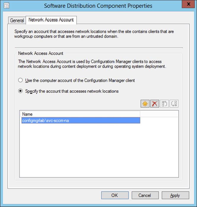
Figure 10.2 Software Distribution Component Properties dialog box
5. Click OK.
The Network Access account must have access to the computer that is deployed and to the content on the distribution points. Normally a Network Access account has permission if it’s a member of the Domain Users Active Directory group.
Configuring the State Migration Point Role
The next step in preparing Configuration Manager 2012 for OSD is to set up a state migration point. The state migration point is used to store user-migrated settings and data during the operating system image deployment. This state migration point is a site system role within Configuration Manager 2012, and it will need to be assigned to a server. Follow these few steps to set up the state migration point role:
1. Open the Configuration Manager 2012 console, select the Administration workspace, and expand Overview ⇒ Site Configuration ⇒ Servers And Site System Roles.
2. Select the site server for which you want to install and configure the state migration point, and click Add Site System Roles on the Home tab of the ribbon.
3. On the Add Site System Roles Wizard’s General page, click Next twice.
4. You will be presented with the System Role Selection page; select State migration point, and click Next.
5. On the State Migration Point page, shown in Figure 10.3, click the starburst icon to create a new storage folder.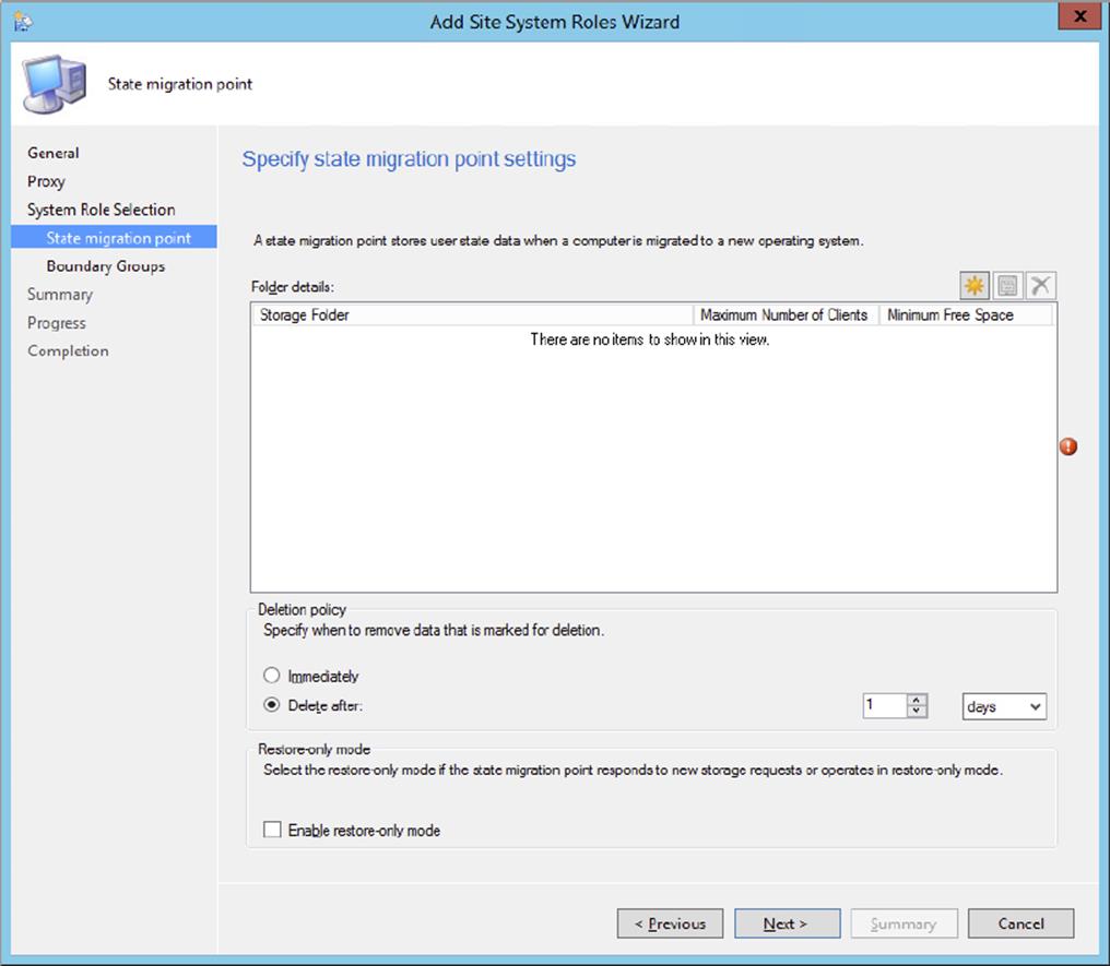
Figure 10.3 Add Site System Roles Wizard—State Migration Point page
6. Create a new storage folder in the Storage Folder Settings dialog, shown in Figure 10.4.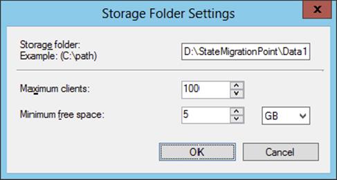
Figure 10.4 Designating a storage folder
This allows you to enter the path to use when storing state migration data.
7. Under the storage folder you also need to configure the maximum number of clients that are allowed to store the data and the minimum required free space on the disk.
A way to determine the size for your state migration point is to identify the number of deployments that must take place, the average size of the user state, and how long the user state must be stored. Be sure to keep your drive from running out of free space by configuring a minimum free space for the disk where the storage folder is located.
8. Click OK to return to the State Migration Point page.
You can change the Deletion Policy setting if you think one day is too long or not long enough until the user data is removed from the state migration point.
Enabling the Restore-Only Mode option will result in the state migration point responding only to restore requests.
9. Click Next to configure boundary groups for the site system.
10.Click Next, and you will be taken to the Summary page.
11.Click Next to allow Configuration Manager to create the new site role.
This brings up the Wizard Completed page.
12.Click Close.
Don’t Configure the Deletion Policy to Delete User State Immediately
A best practice from Microsoft is not to set the deletion policy to delete a user state immediately after it is marked for deletion. If an attacker is able to retrieve the user state before a valid computer does, the user state would be deleted before that time. Set the deletion interval to long enough to verify the successful restore of the user state data.
Configuring PXE on Distribution Points
To allow Configuration Manager 2012 to use OSD for deploying to bare-metal devices, you need to configure PXE on the distribution points, for which you will need to set up the Network Access account, which you did earlier in this chapter. You will also need to ensure that the Configuration Manager client upgrade package has been configured and is ready for deployment, as you also did earlier in this chapter. Finally, you need to ensure that the boot image is set up as a package.
To be able to use PXE on a distribution point site server, you also need to install Windows Deployment Services (WDS) on that server.
Installing Windows Deployment Services
You can install Windows Deployment Services through Add or Remove Programs on Windows 2003 SP2 or higher machines. If you do not install the Windows Deployment Services feature within Windows, Configuration Manager 2012 will automatically install this feature when enabling the PXE feature on the distribution point.
The next stage in preparing Configuration Manager 2012 for OSD is to set up PXE support. Configuration Manager no longer has a PXE service point; the PXE feature is embedded in the distribution point role. You need to enable and configure the PXE feature per distribution point.
Follow these few steps to set up the PXE feature:
1. Open the Configuration Manager 2012 console, select the Administration workspace, and expand Overview ⇒ Distribution Points.
2. Select the site server on which the distribution point resides, and click Properties on the Site Role tab of the ribbon.
3. Select the PXE tab and click Enable PXE Support For Clients.
When you enable the feature, you will see a Review Required Ports For PXE dialog box, shown in Figure 10.5. This dialog box informs you that Configuration Manager 2012 must have some UDP ports opened on the server.
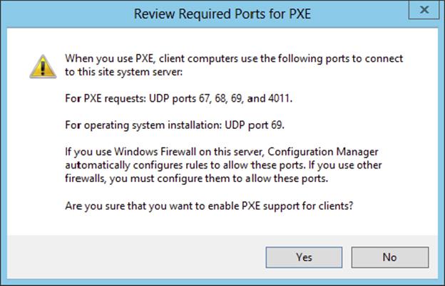
Figure 10.5 Review Required Ports For PXE dialog box
4. Click Yes to continue enabling PXE support for clients.
5. After enabling the feature, you can configure how Configuration Manager will allow incoming PXE requests, as shown in Figure 10.6. Click OK when you’ve finished.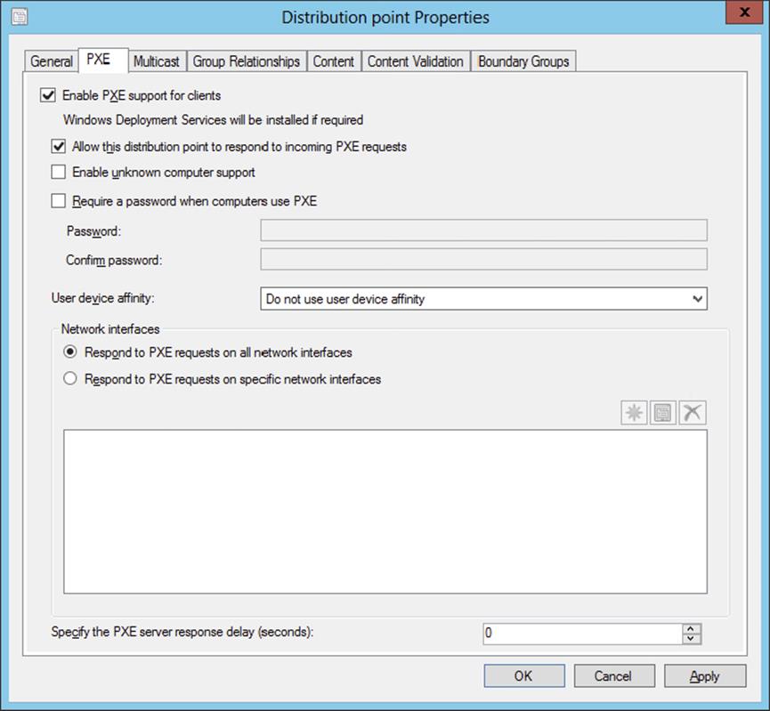
Figure 10.6 PXE settings page
It will take some time for the PXE feature to successfully install on the system. You can monitor the progress of the installation by checking the distmgr.log and smspxe.log files. Windows Deployment Services will be installed if it is not already present on this system.
DHCP and PXE on the Same Server
You’ll need to set up some DHCP options for PXE to boot properly. Specifically, you’ll need to specify options 60, 66, and 67 when the DHCP server is on the same server as your Windows deployment server. Option 60 needs to be set to PXEClient, which is only used in this scenario. Option 66 is the FQDN of the Configuration Manager server, and option 67 should be the path to SMSBoot\<platform>\pxeboot.com.
Distributing the Boot Image Package
The next part of preparing Configuration Manager 2012 for operating system deployment is to distribute the boot image package to a distribution point. This boot image is used to start the computer in the Windows Preinstallation Environment (WinPE) for capturing, prior to deploying the operating system image. This procedure, because of the size of the images, will take some time to complete:
1. From within the Configuration Manager console, choose the Software Library workspace, expand Overview ⇒ Operating Systems, and select Boot Images.
You will notice two boot images for various platforms: one for x64—Boot Image (x64)—and the other for x86 devices—Boot Image (x86). For the purpose of this book, we will concentrate on the x86 boot image, but there is basically no difference in configuring one or the other. The images are configured during the installation of Configuration Manager 2012. However, there are no distribution points assigned for either of the boot images. You need to add both Boot Image Packages to the distribution points.
2. To configure a distribution point, select Boot Images ⇒ Boot Image (x86), and click Distribute Content on the Home tab of the ribbon.
3. This opens the Distribute Content Wizard’s Welcome page; click Next to continue.
4. Select the distribution point you want to use on the Specify The Content Destination page by clicking Add ⇒ Distribution Point.
5. Select the distribution points you want to deploy the boot image to, and click OK.
6. Click Next to review the summary.
7. After reviewing the summary, click Next. Then on the Wizard Completed page, click Close.
It will take some time to copy the boot image package to the distribution point. Do the same for the boot image called Boot Image (x64).
Enabling Boot Images for PXE
The last part of preparing Configuration Manager 2012 for OSD is enabling both of the boot images to be available for PXE:
1. From within the Configuration Manager console, choose the Software Library workspace, expand Overview ⇒ Operating Systems, and select Boot Images.
2. Select the boot image for which you want to enable PXE support, and click Properties on the Home tab of the ribbon.
3. Click the Data Source tab, and enable the Deploy This Boot Image From The PXE-Enabled Distribution Point option, as shown in Figure 10.7.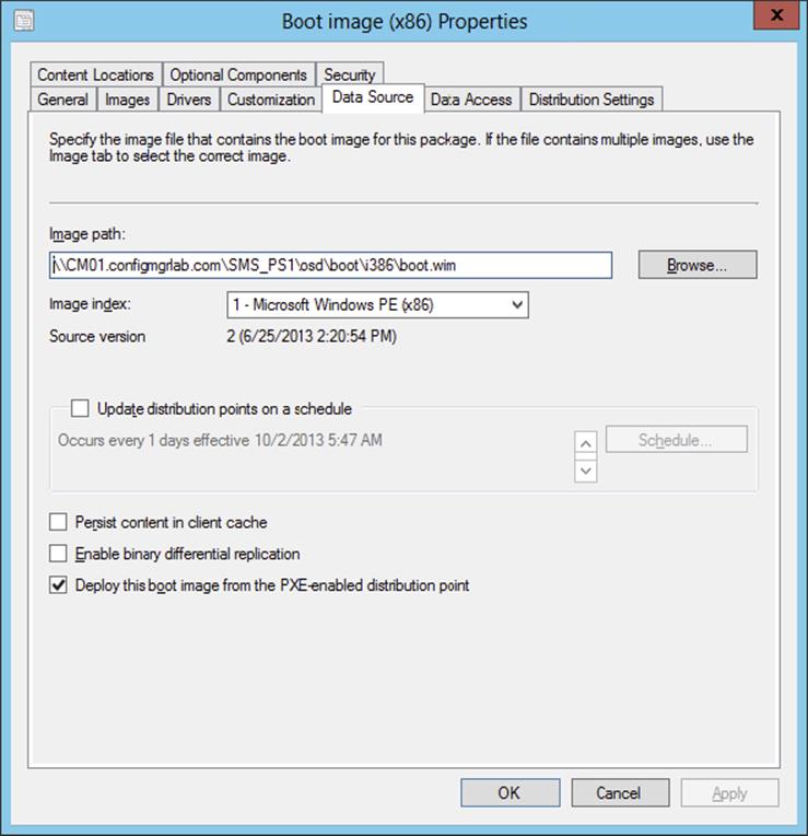
Figure 10.7 Enable the boot image to boot via PXE
4. Click OK.
Configuration Manager will process the change and configure the Windows Deployment Services server to use the boot image from Configuration Manager 2012. Configuration Manager 2012 will place the boot image in the <drive>\RemoteInstall\SMSImages folder.
Let’s review the steps briefly for configuring Configuration Manager 2012 for OSD:
1. First, you configure the Network Access account, and then you create the client install package.
2. Second, you set up the state migration point and PXE support for Configuration Manager 2012.
3. Finally, you deploy the boot images to the distribution points and PXE-enabled distribution points.
Adding Operating System Source
The next step after preparing Configuration Manager 2012 for OSD is to add the source content of the default operating systems. Adding a source of an operating system that you can use for the build and capture process can be done in two ways:
1. Adding an Operating System Package The operating system install packages can be used to build and capture a reference image that you can deploy with Configuration Manager 2012 by using the setup. With Configuration Manager 2012 R2 and the default boot images, only Windows 8.x operating system installers are supported. To be able to build and capture earlier versions, boot images based on the Windows Automated Installation Kit must be created and added to Configuration Manager. Adding legacy boot images is covered later in this chapter. Using the Build And Capture Task Sequence Wizard will give you the only option of selecting an operating system image. You need to change the task sequence step that installs the operating system image after the task sequence is created.
2. Adding a Default INSTALL.WIM image as an Operating System Image Another way is to add the default INSTALL.WIM as an operating system image to Configuration Manager. The INSTALL.WIM file can found in the source of the DVD or ISO that holds the operating system. The Build And Capture Task Sequence Wizard lets you select the operating system image directly.
You can add an operating system install source package by following the next procedure:
1. From within the Configuration Manager console, choose the Software Library workspace, expand Overview ⇒ Operating Systems, and select Operating System Installers.
2. Click Add Operating System Installer on the Home tab of the ribbon, and fill in the UNC path to the install source of the operating system, as shown in Figure 10.8.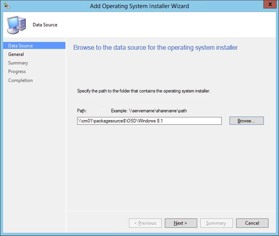
Figure 10.8 Create an operating system install package
3. Click Next.
4. Supply the operating system install package with a name, version, and comments, and click Next.
5. Review the summary, and click Next.
6. When finished, click Close.
After creating the operating system installer package, distribute the package to select distribution points in your hierarchy. The source of an operating system install package in combination with the default boot images can be one of the following operating systems:
· Windows 8
· Windows 8.1
· Windows Server 2012
· Windows Server 2012 R2
You can add an INSTALL.WIM file from an operating system source by following the next procedure:
1. From within the Configuration Manager console, choose the Software Library workspace, expand Overview ⇒ Operating Systems, and select Operating System Images.
2. Click Add Operating System Image, and browse to the root UNC location of the install source on your package source share. From there browse to Sources and select the INSTALL.WIM file, as shown in Figure 10.9.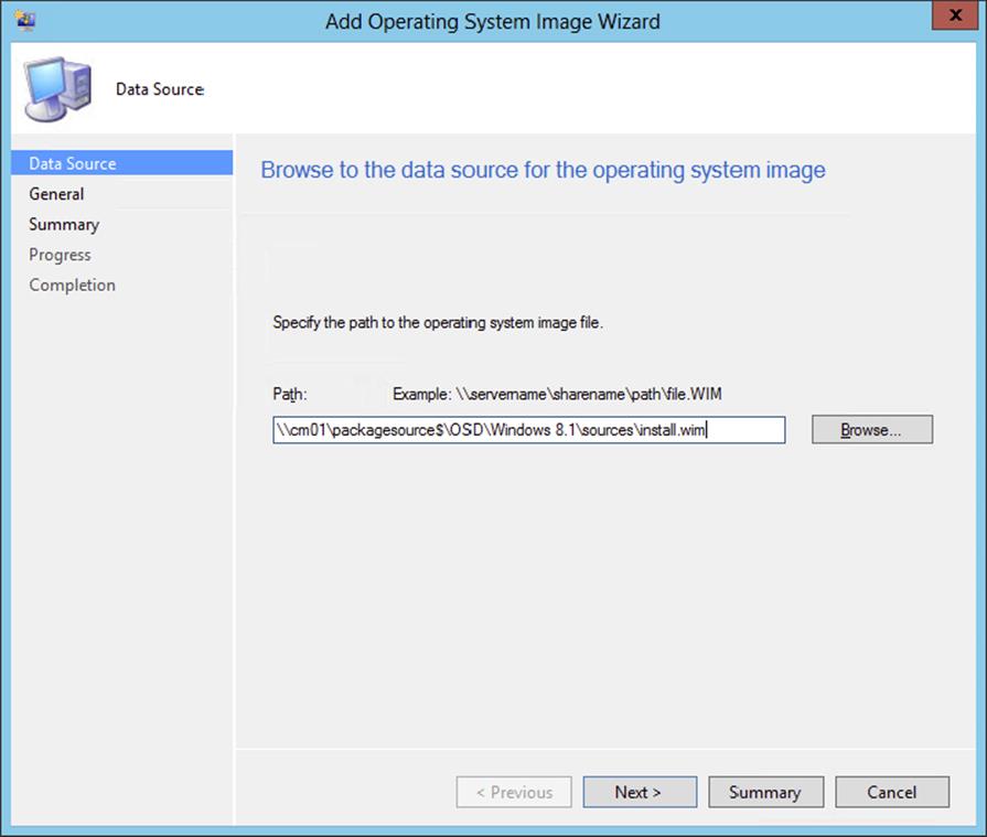
Figure 10.9 Add an INSTALL.WIM file as an operating system image.
3. Click Next and supply the operating system image with a name, version, and comments if necessary, and click Next again.
4. Review the summary, and click Next.
5. When finished, click Close.
After creating the operating system image package, distribute the package to the distribution points in your hierarchy. By using this method, you can build and capture the following operating systems:
· Windows Vista
· Windows 7
· Windows 8
· Windows 8.1
· Windows Server 2008
· Windows Server 2008 R2
· Windows Server 2012
· Windows Server 2012 R2
Developing a Task Sequence for Creating a Capture Image
Now we will show how to create a task sequence that will be used to capture an image of a workstation. A task sequence is a way for Configuration Manager 2012 to perform one or more steps or tasks on a client computer without requiring user intervention, also known as Zero-Touch deployment. A task sequence can consist of a single step or multiple tasks grouped together to perform functions. The tasks can depend on other tasks to complete successfully or be independent of each other.
There are two options for creating task sequences for OSD:
· Task sequences used with PXE boot
· Task sequences used with media boot
Task Sequences Used with PXE Boot
When you enable PXE on the distribution points, you can simply create a build-and-capture task sequence that will take care of the build-and-capture process. Take the following steps to create a task sequence for creating an image:
1. From within the Configuration Manager console, select the Software Library workspace, expand Overview ⇒ Operating Systems, and select Task Sequences.
2. Click Create Task Sequence on the Home tab of the ribbon, and select the Build And Capture A Reference System Image option.
3. Give the task sequence a name (for instance, Build And Capture Windows 8.1 Enterprise), select a boot image that will support your operating system version and platform, and click Next.
4. Select the operating system image package, and supply a password that you will remember if you need to troubleshoot. Selecting the operating system image is the default; if you want to use the operating system installer, you need to change the task sequence after the wizard is finished.
The local administrator account will be disabled if you do not supply a password. Do not supply a product key if you are building and capturing Windows 7, Windows 8.x, Windows Server 2008, or Windows Server 2012 images, as shown in Figure 10.10. Supplying a product key while building and capturing will cause the process to fail with exit error 31.
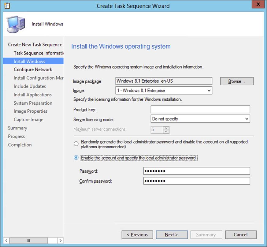
Figure 10.10 Define which Windows operating system will be captured.
5. Click Next to move to the next page of the wizard.
6. Supply a name for the workgroup that you want to join while you are building and capturing your operating system.
Be sure to join a workgroup so that no Group Policies are applied while you are building and capturing your reference image.
7. Click Next after supplying the name of the workgroup.
8. Select the Configuration Manager 2012 client package, and supply the SMSMP=<siteservername> installation properties, as shown in Figure 10.11.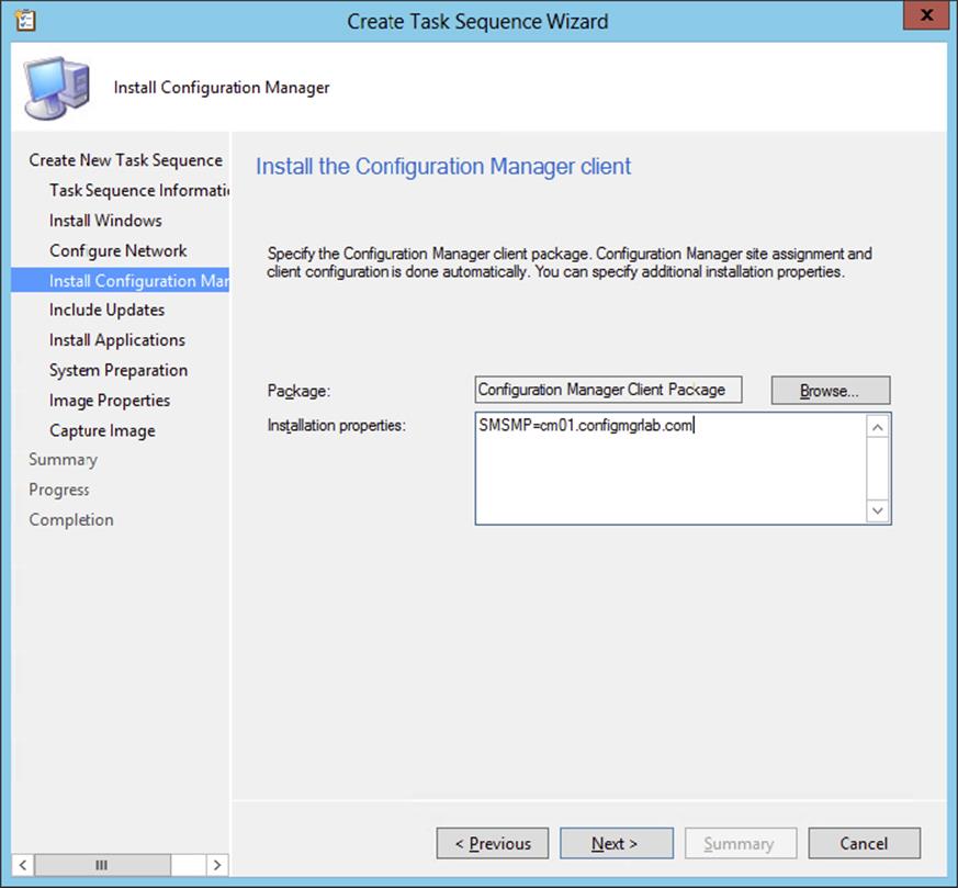
Figure 10.11 Install the Configuration Manager client task.
Supplying the installation properties allows you to install approved software updates via the Software Updates feature while the operating system is part of a workgroup.
9. Click Next.
10.Decide whether you want to install software updates during the build-and-capture process.
Best practice is that you install all software updates that are approved in the Software Updates feature in Configuration Manager.
11.Click Next to be able to select the application that you want to install while building and capturing your reference operating system image, and click Next again.
12.Depending on the source of your operating system, you may need to supply a system preparation tool; click Next.
When deploying Windows XP SP3, you need to use Sysprep to seal the operating system and make it anonymous before capturing. Windows 7, Windows Server 2008, and higher operating systems have a built-in system preparation tool.
13.Supply information about the image, such as creator, version, and description, and click Next.
14.Supply a UNC path and a filename for the captured operating system image, as shown in Figure 10.12, and click Next.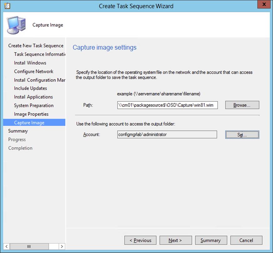
Figure 10.12 Captured image path and filename
15.Supply an account with Write permission to the share where the image will be captured. Click Test Connection if you want to test whether the user name and password are correct.
16.Click Next to see the summary.
17.After reviewing the summary, click Next to create the task sequence.
18.When finished, click Close.
As mentioned earlier, if you want to use the operating system installer image to build and capture the operating system image, you need to change the just-created build-and-capture task sequence. This is optional.
Optional:
1. Select the just-created task sequence and click Edit on the Home tab of the ribbon of the Configuration Manager console.
2. Select the Apply Operating System task, and click the Apply Operating System From An Original Installation Source radio button, as shown in Figure 10.13. Then click Browse to select Windows 8.1 Enterprise Operating System Install Package For This Task Sequence. Click OK to save the changes.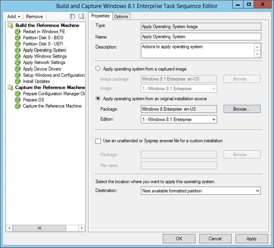
Figure 10.13 Apply Operating System task
Task Sequences Used with Media Boot
If you do not want to enable PXE support on your distribution points or you want to capture a custom reference computer, you can also create a build-and-capture task sequence that runs from media. Follow these steps to create a task sequence for creating a capture image:
1. From within the Configuration Manager console, choose the Software Library workspace, expand Overview ⇒ Operating Systems, and select Task Sequences.
2. From the Home tab of the ribbon, click Create Task Sequence Media. This opens the Select Media Type page, shown in Figure 10.14.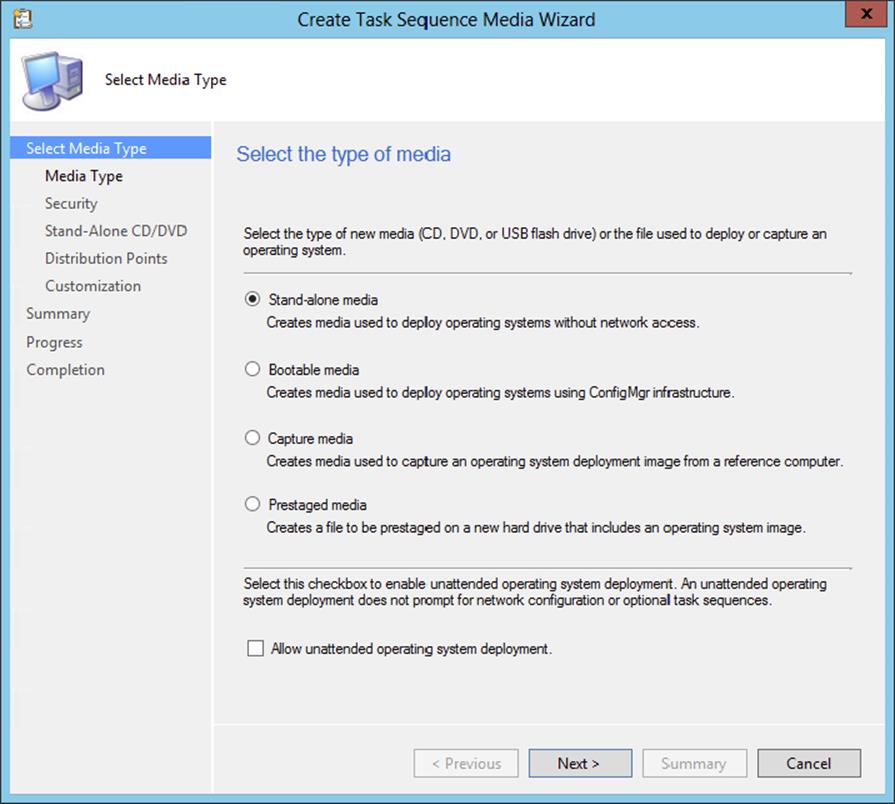
Figure 10.14 Create Task Sequence Media Wizard—Select Media Type page
3. On the Select Media Type page, select Capture Media, and then click Next.
By selecting Capture Media, you will be creating the capture media that will be used to capture the operating system image.
On the wizard’s Media Type page, shown in Figure 10.15, you can select the type of media to create.
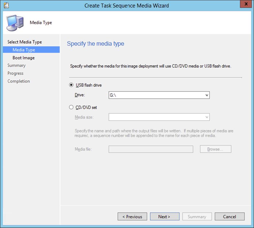
Figure 10.15 Create Task Sequence Media Wizard—Media Type page
4. For this example, select USB Flash Drive, select the available drive, and click Next. Click Yes at the dialog that warns you that the device will be formatted.
5. On the Boot Image page, shown in Figure 10.16, specify the boot image and distribution point you want to use. Click Browse, and select the boot image, and click Browse to select the distribution point. Click Next to continue.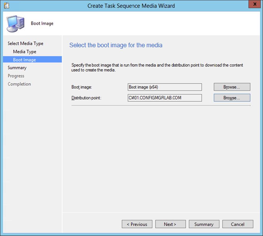
Figure 10.16 Create Task Sequence Media Wizard—Boot Image page
6. Click Next on the Summary page, and Configuration Manager 2012 will begin creating the capture media on the USB stick.
7. Finally, you will be presented with the Wizard Completed page; click Close.
When finished, you can use the USB stick to boot up the computers that you will be using to build your operating system image. If you have selected to create an ISO file, you can now burn that ISO file to a CD and use that CD to boot up the computers in which you will be building your operating system image.
Capturing an Operating System Image
Configuration Manager 2012 supports two different ways of capturing an operating system image. You can use the fully automatic way, by using the build-and-capture task sequence, or you can capture a custom reference computer, by using the capture media created earlier.
Building and Capturing Automatically
When building and capturing an operating system image with the specially designed build-and-capture task sequence, you can fully automate the build-and-capture process. This way you know that the result of a task sequence is always the same, and no user intervention is necessary.
To be able to use the build-and-capture task sequence created earlier, you need to make the task sequence available for deployment, as follows:
1. From within the Configuration Manager console, choose the Software Library workspace, expand Overview ⇒ Operating Systems, and select Task Sequences.
2. Select the build-and-capture task sequence, and click Deploy on the Home tab of the ribbon.
3. Specify the collection where the reference computer resides, and select the distribution point(s) where the content needs to be deployed to, as shown in Figure 10.17.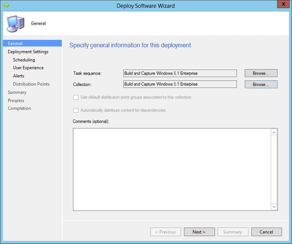
Figure 10.17 Specify deployment information
Be sure that you create a special collection for building and capturing operating systems.
4. Click Next to proceed in the wizard.
Now you need to configure the deployment settings; for Purpose you can select either Available or Required. If you choose Available, you need to press F12 to enter the PXE boot procedure and select the task sequence in the WinPE environment. If you choose Required, the machine will boot into WinPE during the PXE boot procedure. You also need to configure in which scenario the deployment is available.
1. Only Configuration Manager Clients A task sequence deployment can be made available for Configuration Manager clients only. This means that an operating system with a Configuration Manager client must be active to be able to receive and start the task sequence deployment. This option can be used best in refresh client scenarios.
2. Configuration Manager Clients, Media And PXE If the task sequence that needs to be deployed must be available in all scenarios, you need to select this option.
3. Only Media And PXE When a task sequence like the build and capture one needs to be available only for media and PXE, then you need to select this option. Another scenario is bare-metal deployment.
4. Only Media And PXE (Hidden) When a task sequence like the build and capture one needs to be available only for media and PXE, then you need to select this option. Another scenario is bare-metal deployment. This is often used for test purposes. To be able to use the hidden deployment, you need to set the SMSTSPreferredAdvertID variable with the AdvertID of the Task Sequence as the value at the collection level where the task sequence is deployed.
Click Next.
5. Select the option Only Media And PXE, as shown in Figure 10.18, and click Next to configure the deployment settings.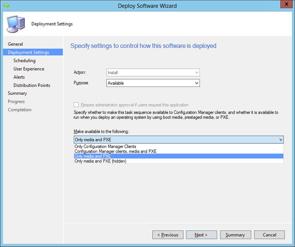
Figure 10.18 Specify the deployment settings.
6. Configure the scheduling settings, and click Next.
7. Since you are configuring a deployment for a build-and-capture task sequence, no user experience options need to be configured, so click Next.
8. Configure Alerts options for failed deployments; you can set a threshold for alerts to be sent when the threshold is higher than a percentage of failed deployments. Click Next to proceed.
9. Configure the distribution point settings, and click Next to review the summary.
10.After reviewing the summary, click Next and then Close.
After making the build-and-capture task sequence available for deployment, you can go into action and build and capture the image. To begin, shut down your reference computer and be sure that you can boot from the network. To cause less overhead on drivers, building and capturing images is often done with virtual machines. To use the following procedure, be sure that your computer object in Configuration Manager is added to the collection where the task sequence is deployed.
1. Start your computer or virtual machine and boot into PXE.
2. At the Welcome To This Task Sequence screen, click Next.
3. Select the Build And Capture Windows 8.1 Enterprise task sequence, as shown in Figure 10.19, and click Next.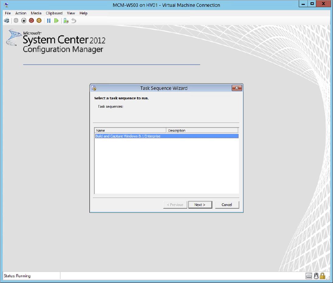
Figure 10.19 Select the task sequence
After the build-and-capture process, described earlier, has finished, you will have your captured Windows image. The computer will restart in Windows.
The captured WIM image can be used for deployment to the computers in your environment. Be sure to always test your deployment in a test environment.
Capturing a Reference Computer
When creating an image of a reference computer, you need to be aware of a few issues. First, ensure that the computer is a member of a workgroup instead of a member of the domain. This is a required step; if the reference computer is a member of the domain, you will be required to remove it from the domain to create the image of the operating system of the computer. Second, we recommend removing the Configuration Manager client from the machine. This is not a requirement, just a recommendation.
1. To begin creating an image of the reference computer, insert the CD that was created from the ISO file you created earlier.
2. Run LaunchMedia.cmd located in the root folder on the CD. This opens the Image Capture Wizard.
3. Click Next to open the Image Destination page, shown in Figure 10.20, which allows you to specify where to copy the image when the capture is completed.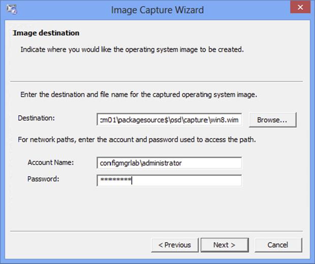
Figure 10.20 Image Capture Wizard—Image Destination page
4. Fill in the correct information, and click Next.
As you can see, we copy the WIM file to our site server.
You will now be able to add some information about the image on the Image Information page. You can fill in the Created By, Version, and Description fields for the WIM file.
5. Fill in this information with as much detail as you can; then click Next.
6. On the Summary page, click Finish to begin the capture phase.
An Installation Progress window appears, telling you that the Image Capture Wizard is working and running in the background. When the image capture is complete, a System Restart message will appear, and the system will reboot. When the system reboots, it will boot into WinPE and begin capturing the system. This process can be a lengthy one, so be patient while the operating system is being captured.
Once the image capture is complete, you will see the Image Capture Wizard success message, shown in Figure 10.21.
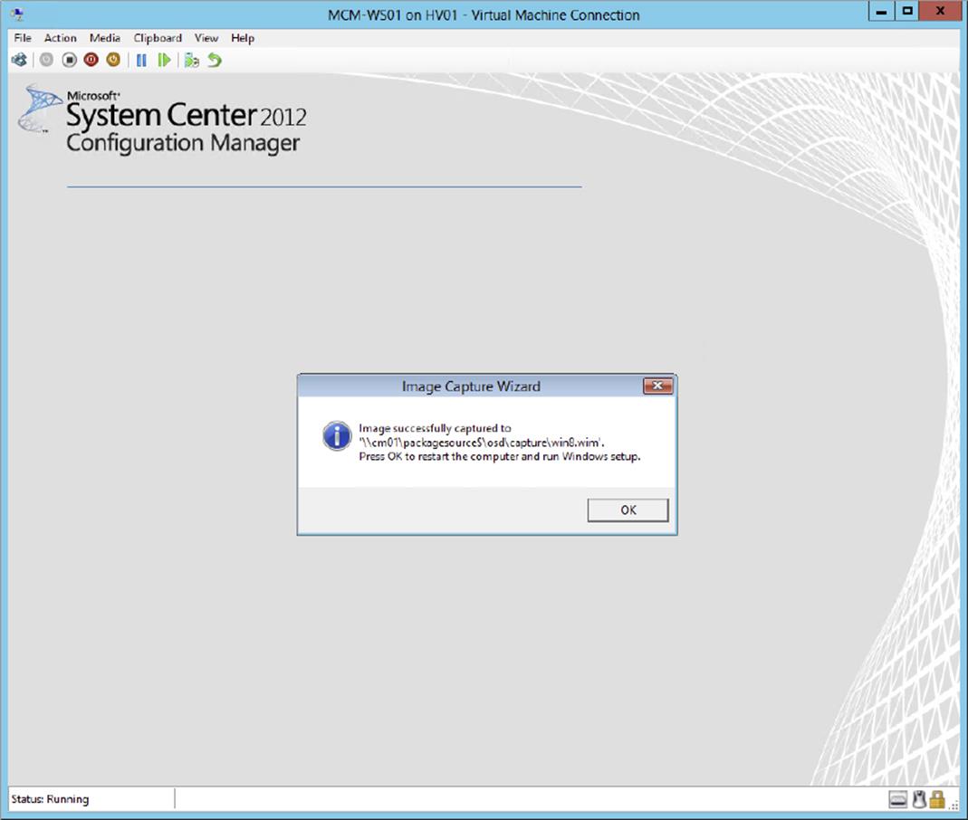
Figure 10.21 Image capture success message
7. Click OK to allow the machine to reboot and return to the operating system.
Deploying an Image
Since you’ve now successfully captured an image, you need to add this operating system image to Configuration Manager. Then you need to deploy this image by creating a task sequence and deploy this task sequence to the computers in your environment. Always be sure to thoroughly test the image in a separate test environment before deploying it into production.
Adding a Captured Image
The WIM file that you just created needs to be added as an available operating system for Configuration Manager 2012. To deploy this image, follow this procedure:
1. From within the Configuration Manager console, select the Software Library workspace, expand Overview ⇒ Operating Systems, and select Operating System Images.
2. Click Add Operating System Image on the Home tab of the ribbon.
This opens the Add Operating System Image Wizard’s Data Source page.
3. Ensure that the (UNC) Path field points to the location where the WIM file was created, and click Next.
The General page allows you to customize the Name, Version, and Comments fields for the image file.
4. Fill in the appropriate information, and click Next.
5. The Summary page will be displayed; review the information and click Next.
6. Finally the Wizard Completed screen will appear. On this page, click Close.
Distributing and Deploying the Image
Next, you need to configure a distribution point in order to distribute this image. This step is a little different from the steps for assigning distribution points for packages that we discussed elsewhere in this book:
1. From within the Configuration Manager console, choose the Software Library workspace, expand Overview ⇒ Operating Systems, and select Operating System Images.
2. Select the image that you added, and click Distribute Content on the Home tab of the ribbon.
3. In the Distribute Content Wizard click Next.
4. Click Add and select Distribution Point or Distribution Point Group.
5. Select in the Add Distribution Points or Add Distribution Point Groups dialog the distribution points or groups that you want to distribute the WIM image to, and click OK.
6. Click Next to review the summary.
7. After reviewing the summary, click Next and then Close.
Developing a Task Sequence for Deployment
Now you will need to create a task sequence for deploying the Windows operating system image. Creating a task sequence will give Configuration Manager 2012 a series of steps to perform on the new installation of the workstation:
1. From within the Configuration Manager console, select the Software Library workspace, expand Overview ⇒ Operating Systems, and select Task Sequences.
2. Select Create Task Sequence on the Home tab of the ribbon.
This will open the New Task Sequence Wizard’s Create A New Task Sequence page.
3. Because you have already built an image of a Windows client, select Install an existing image package, and then click Next.
This opens the New Task Sequence Wizard’s Task Sequence Information page.
4. Specify the task sequence name and a comment, and specify the boot image to use during the installation of the image. Click Next after supplying the information.
The Install Windows page, shown in Figure 10.22, allows you to specify the Configuration Manager 2012 image package containing the operating system you want to install.
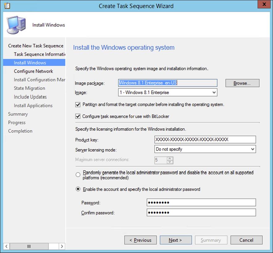
Figure 10.22 Create Task Sequence Wizard—Install Windows page
5. Click the Browse button to find the image of the operating system you want to install, and click OK.
6. If you want to partition and format the target computer before installing the operating system, leave the Partition box selected, and format the target computer before installing the operating system.
7. Keep the Configure Task Sequence For Use With BitLocker option enabled if you want to enable BitLocker during the deployment of the Windows image.
8. Enter the licensing information for the version of Windows you are installing in the Product Key field, and click Next.
9. On the Configure Network page, select the domain or workgroup to join.
If you select to join a domain, you can specify which OU to put the computer in once it joins the domain. If you select to join a domain, you will need to specify the account that has permission to join computers to a domain. The Configuration Manager Network Access Account is often used to join the computer to the domain. You need to delegate this access to the user account. Verify the account by testing the connection after configuring the account.
10.Click Next to continue.
Now all the work you did earlier will finally be put to use.
11.On the Install Configuration Manager Client page, specify any additional installation properties. Click Browse if you do not want to use the default Configuration Manager 2012 client package.
12.Then click Next to continue.
The Create Task Sequence Wizard page that appears is State Migration, shown in Figure 10.23, which allows you to configure the user state migration capture.
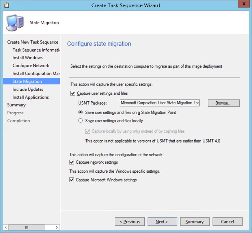
Figure 10.23 Create Task Sequence Wizard—State Migration page
13.Select or deselect whether you want to capture network and Microsoft Windows settings.
14.Click Browse, if you do not want to use the default User State Migration Tool package, and then click Next.
After you’ve configured the state migration, the Include Updates page will appear, which allows you to specify whether the client will get mandatory, all, or no software updates after the image has been installed.
15.Configure the installation of software updates, and click Next.
Now you have the option to install additional applications by adding the configured applications to the task sequence. This is extremely useful if you have a large number of applications you want installed on each system after the operating system has been installed. Figure 10.24 shows the Install Applications page, where you can specify the additional applications.
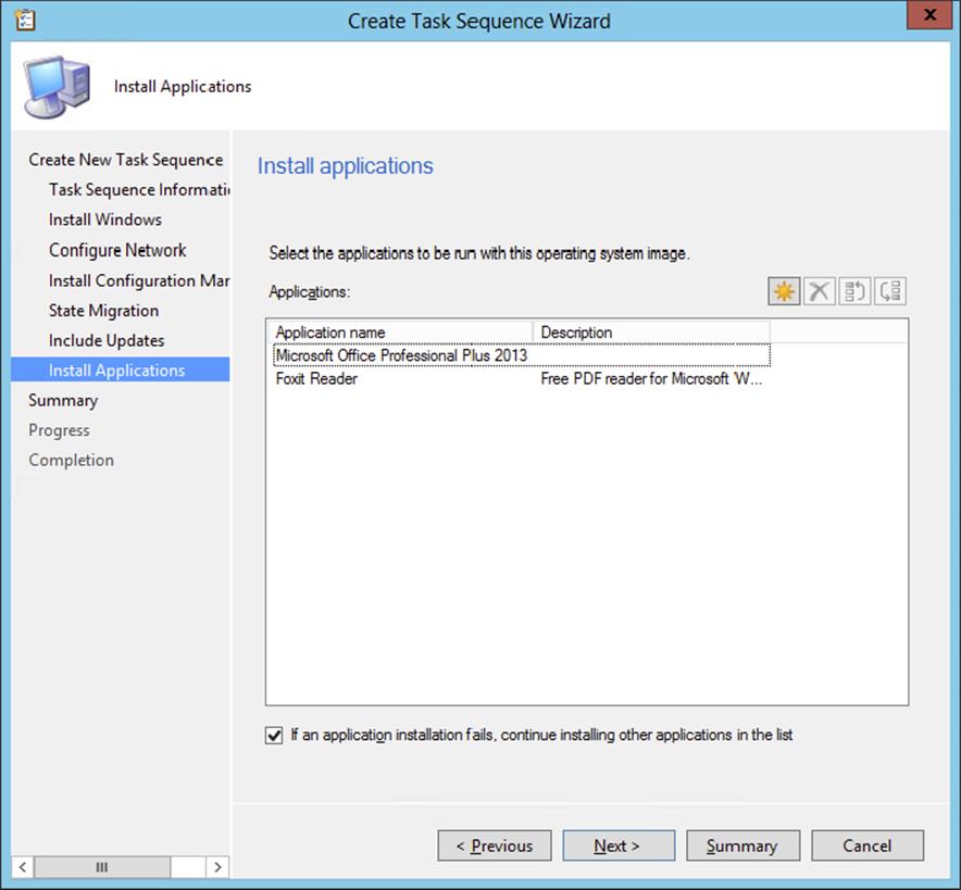
Figure 10.24 Create Task Sequence Wizard—Install Applications page
16.Select the option If An Application Installation Fails, Continue Installing Other Applications In The List if you want to let the task sequence proceed with its tasks.
17.Click Next once you have the additional applications specified.
18.Click Next on the Summary page, and Configuration Manager 2012 will complete the Create Task Sequence Wizard.
19.Click Close.
Preserve the Drive Letter in Your Image, or Not
A disadvantage of deploying the default INSTALL.WIM files is that Microsoft created the INSTALL.WIM image by installing the Windows 7 version to the D: drive. For this reason the Windows operating system is installed by default to the D: drive.
You can disable this default behavior by setting a task sequence variable at the top of the task sequence.
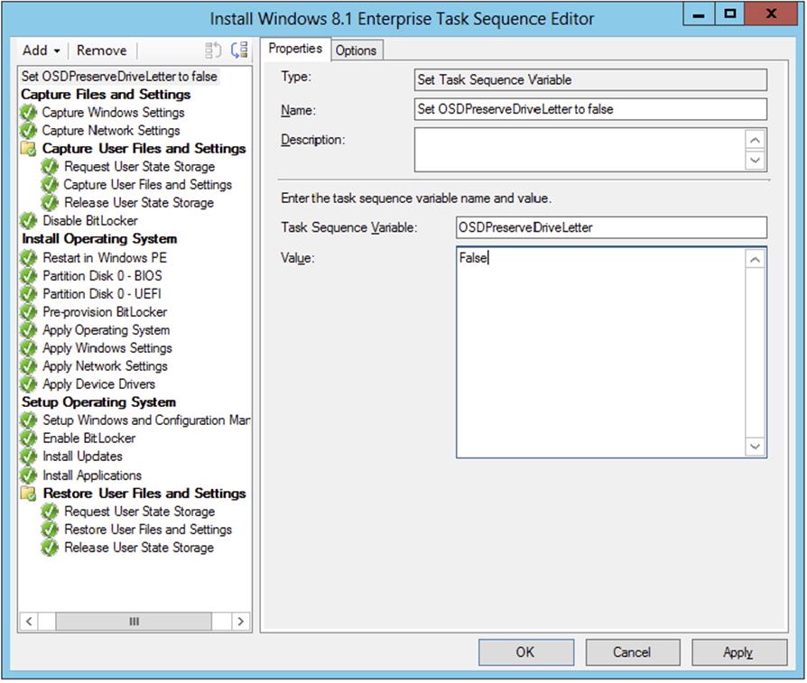
Adding the task sequence variable OSDPreserveDriveLetter = False to the task sequence allows you to install the default INSTALL.WIM image to drive C: instead of drive D:.
Deploying the Task Sequence
You have successfully created a new task sequence to install a new operating system on a machine, join the system to the domain, and install the Configuration Manager 2012 client on the machine once it comes online. However, the task sequence won’t do you any good unless you deploy it to a collection. Take the following steps to do so:
1. From within the Configuration Manager console, choose the Software Library workspace, expand Overview ⇒ Operating Systems, and select Task Sequences.
2. Select the task sequence you want to deploy, and click Deploy on the Home tab of the ribbon.
3. Click Deploy to open the General page of the Deploy Software Wizard.
4. Click Browse to find the collection where you want to install this operating system package, and then click Next to continue.
The next wizard page is Deployment Settings, shown in Figure 10.25.
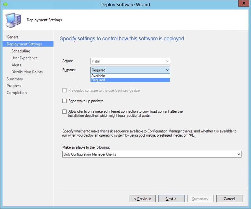
Figure 10.25 Deploy Software Wizard—Deployment Settings page
5. Supply the purpose of the deployment.
· If you want to let your users choose to reinstall their operating system, choose the Available option.
· If you want the installation to start automatically, choose the Required option.
Choosing the Required option enables you to send wake-up packets to the computers in the collection. Of course, you need to first configure Wake On LAN support in Configuration Manager 2012. At this time you do not need to enable the option for PXE support; the task sequence you are creating is used to refresh your Windows installation, so you will be making the deployment available only for Configuration Manager clients.
6. Click Next to continue.
The next step is to configure the scheduling options for the deployment.
7. Configure the availability of the deployment and when the deployment will expire.
8. Define the assignment schedule, and be sure to set the rerun behavior to Rerun if the previous attempt failed.
If you do not set this option, the deployment will rerun as soon the deployment is finished, thereby creating a deployment loop.
9. Click Next to proceed.
10.On the User Experience page, specify how users are notified about the deployment and how they interact with the deployment.
We prefer to show the task sequence progress to let the end user know that the computer is being reloaded.
11.Click Next to proceed, and configure the Alerts options for this deployment.
12.Click Next, configure how to run the content for this deployment on the Distribution Points page, and click Next again.
13.Review the summary, click Next, and click Close when the wizard has finished processing the deployment.
Now you have created the deployment for the operating system deployment, and any system in the collection you specified will get the new deployment during the next policy refresh. Once the policy refresh takes place, the workstation will receive the Assigned Program About To Run notification. Once the installation begins, you will see the Installation Progress message box in Windows, as shown in Figure 10.26.
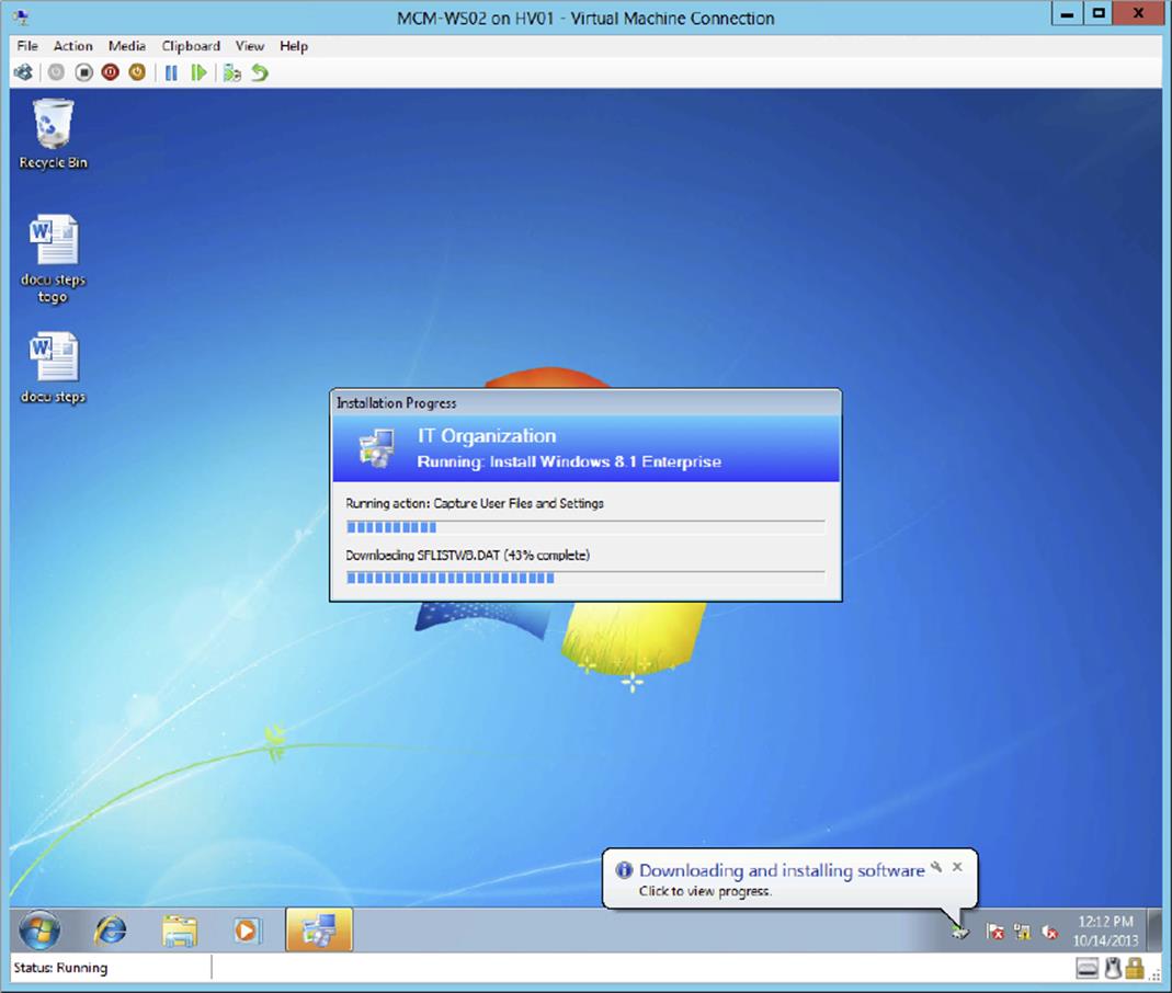
Figure 10.26 Installation Progress message box
The system will automatically reboot and then begin the boot to WinPE, as shown in Figure 10.27.
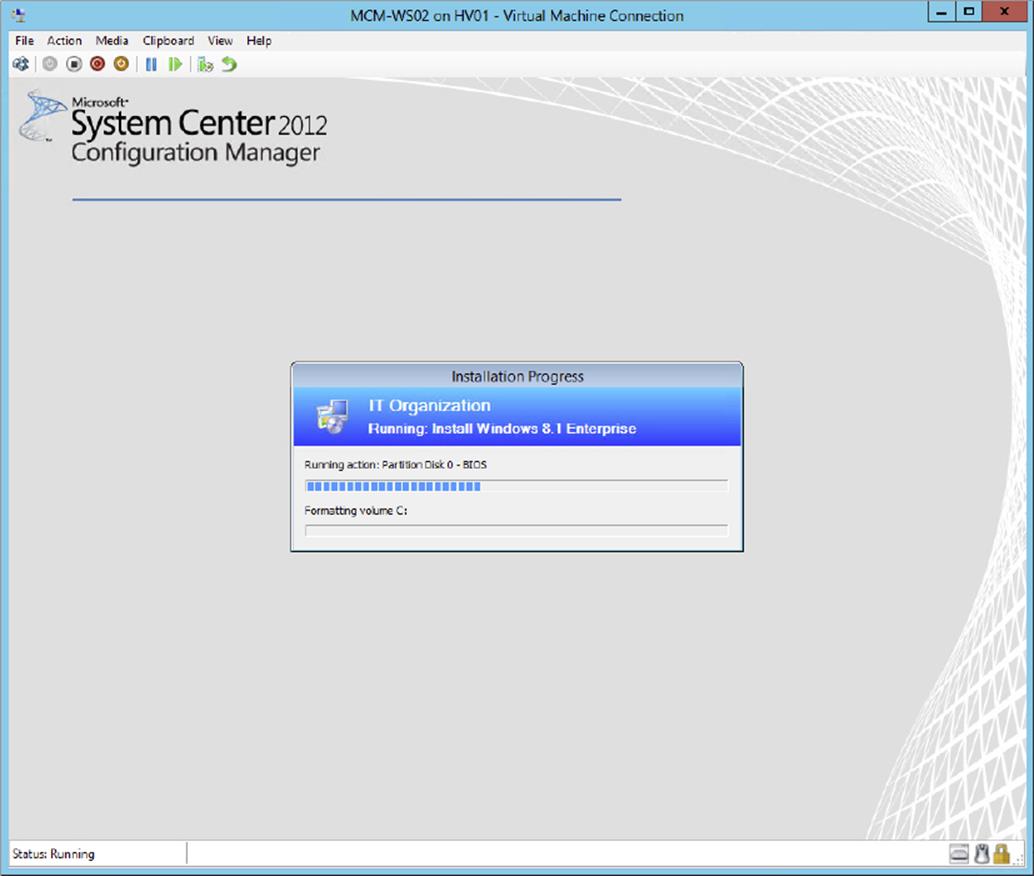
Figure 10.27 Booting to WinPE
The installation will take some time to complete. During this install, Configuration Manager is gathering the user state and saving the date in the USMT folder on the site server, which you configured earlier in this chapter. You can monitor the <drive>:\USMTDatafolder on the site server to see the user state migration data being copied to the server.
Configuration Manager will push the new operating system down to the new machine and then join it to the domain, install the Configuration Manager client, and finally copy back all the user data on the client.
You can monitor the progress of the operating system deployment in the Deployment Status window, shown in Figure 10.28.
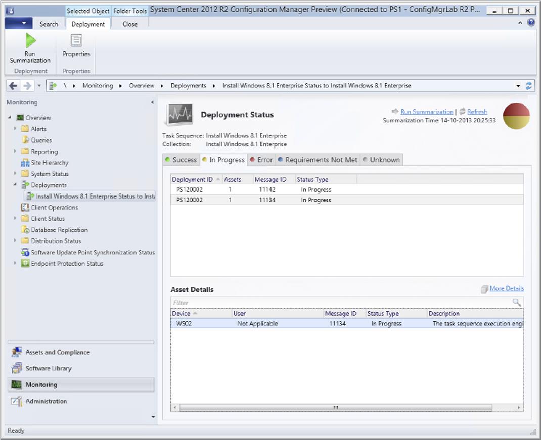
Figure 10.28 Monitoring the OSD deployment status
1. From within the Configuration Manager console, choose the Monitoring workspace, expand Overview ⇒ Deployments, and select the deployment that you want to monitor.
2. After selecting the deployment, click Run Summarization on the Home tab of the ribbon.
3. After the summarization is updated, click View Status on the Home tab of the ribbon to see the status of the deployment, as shown in Figure 10.28.
4. While viewing the status, you can refresh the status by clicking Run Summarization or Refresh.
5. While monitoring the OSD deployment status, you are able to review the completed tasks by selecting More Details and selecting the Status tab of the Asset Message dialog screen, as shown in Figure 10.29.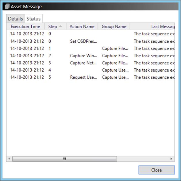
Figure 10.29 Review the task sequence steps in the Asset Message dialog screen.
Deploying the Operating System on Bare Metal
After deploying an operating system in a refresh scenario, you also need to create a task sequence and deployment to be able to deploy an operating system to bare-metal computers. Bare-metal computers are computers without any operating system present.
To deploy an operating system to a bare-metal computer, you can use a CD or DVD to start into WinPE, but you can also boot into PXE to start the WinPE image from the network. Let’s see how this works with PXE. To be able to deploy an operating system to a bare-metal computer, you need to perform the following tasks:
· Import information about a computer.
· Create a task sequence.
· Deploy the task sequence.
Importing Computer Information
Now you are ready to set up a computer association so that Configuration Manager can identify the bare-metal machines that will receive a fresh install. To specify the computer association, you will need to open the Configuration Manager console and proceed as follows:
1. From within the Configuration Manager console, choose the Assets And Compliance workspace and expand Overview ⇒ Devices.
2. Click Import Computer Information on the Home tab of the ribbon.
This will allow you to import a single computer or import many systems from a comma-separated values (CSV) file.
3. Select the option Import Single Computer, and click Next.
This will bring up the Single Computer page, as shown in Figure 10.30.
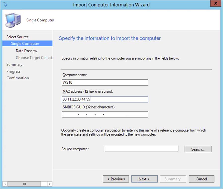
Figure 10.30 Import Computer Information Wizard—Single Computer page
You must enter the computer name along with either the MAC address or the SMBIOS GUID. The computer name is just how the machine will appear in the collections, not what the actual computer will be named.
4. Fill in the appropriate information, and then click Next.
5. This sends you to the Data Preview page; check the information and click Next.
You’ll then see the Choose Target Collection page.
6. Here, specify which collection you want to add to this new machine.
It is extremely important to put all the bare-metal installs into the same collection, used only for bare-metal deployment.
7. Click Next.
8. After specifying the collection, you will see the Summary page. Click Next, and then click Close on the Finish page.
Creating a Task Sequence for the Bare-Metal OSD
When you deploy a bare-metal machine, it is wise to create a dedicated task sequence for this purpose. Once you create this special task sequence, you need to deploy it to a special collection in which you can place the bare-metal computers.
Creating a task sequence for deploying an image to a new machine is very straightforward:
1. From within the Configuration Manager console, choose the Software Library workspace, expand Overview ⇒ Operating Systems, and select Task Sequences.
2. From there, click New Task Sequence on the Home tab of the ribbon of the Configuration Manager console.
This opens the Create New Task Sequence page of the New Task Sequence Wizard.
3. Select the Install An Existing Image Package option, and click Next.
4. On the Task Sequence Information page, fill in the name, optionally add a comment, and select the boot image you want to use for the operating system deployment and click Next.
5. On the Install The Windows Operating System page, select the image package by browsing to the correct image.
6. Because this example is deploying Windows to a bare-metal machine, enable the option to partition and format the target computer.
The next options you can configure are the network settings.
7. On the Configure The Network page, specify whether you want to join the new machine to the domain or join a workgroup. Click Next after configuring the network settings.
A Configuration Manager task sequence will allow you to install the Configuration Manager client during an operating system deployment.
8. On the Install The Configuration Manager Client page, add installation properties if you need to and click Next.
9. Since you are deploying Windows to a bare-metal machine, on the State Migration page, shown in Figure 10.31, deselect all the options because you do not need to worry about capturing any data from these machines. Click Next to configure the installation of software updates.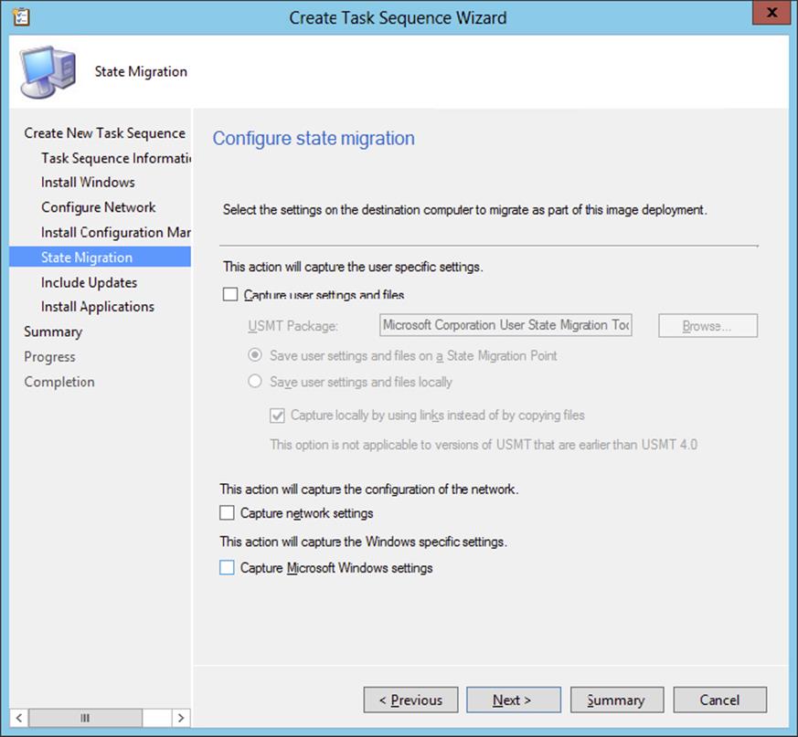
Figure 10.31 Create Task Sequence Wizard—State Migration page
On the Include Updates page, you can now allow Configuration Manager to include software updates during the install.
10.Make the selections you desire, and click Next.
If you have any additional applications you want to deploy, such as Microsoft Office or anything else, on the Install Applications page, you can add any applications to install on the machine after the operating system has been deployed.
11.Click Next to view the Summary page.
12.After viewing the summary, click Next and then Close to complete the wizard.
Deploying the Bare-Metal Task Sequence
After creating the task sequence for bare-metal deployment, you need to deploy this task sequence, as discussed earlier. Be sure to select that the task sequence is available to only media and PXE.
Using the Unknown Computer Collection
You can enable support for unknown computers. Unknown computer support is a feature in Configuration Manager 2012 that will allow unmanaged systems to be managed with Configuration Manager 2012 during an OS deployment. To do so, open the Configuration Manager console, select the Administration workspace, and expand Overview ⇒ Site Configuration ⇒ Servers And Site System Roles. Select the server with the distribution point where PXE is enabled, and click Role Properties in the Site Role section of the ribbon. Browse to the PXE tab in the Distribution Point Properties dialog box, shown here, and select the box Enable Unknown Computer Support.
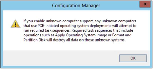
When you enable this option, you will be prompted with the caution message shown next. Assuming you are ready to proceed, click OK.
To create a task sequence for bootable media, open the Configuration Manager console, choose the Software Library workspace, and expand Overview ⇒ Operating System ⇒ Task Sequences. Click Create Task Sequence Media on the Home tab of the ribbon. This opens the Create Task Sequence Media Wizard’s Select Media Type page.
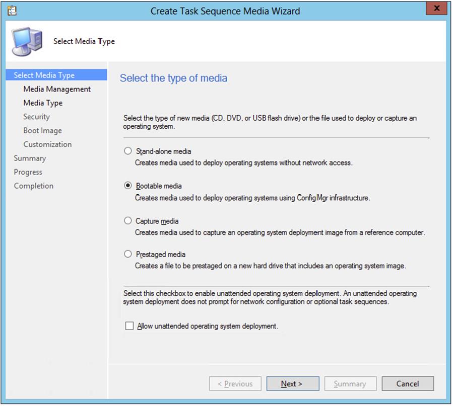
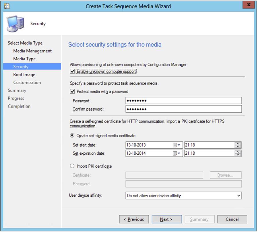
Select Bootable Media, and click Next. Choose Dynamic Media when the media contacts a management point, which redirects the client to a different management point based on the client location in the site boundaries, or choose Site-Based Media when you want to specify a management point. Click Next to configure the media type. On the Media Type page, select the type of media you will be using, either a USB flash drive or a CD/DVD set, and then click Next. The Security page offers the Enable Unknown Computer Support option. Selecting this will allow you to target the unknown computer collection with the operating system deployment.
The next step, after configuring unknown computer support, is configuring the boot image, distribution point, associated management points, and customizations.
After creating the boot media you can create a deployment to this collection for the OSD task sequence, and Configuration Manager will process the task sequence for the unknown computers. Be sure to enable your deployment to be accessible for boot media and PXE.
Installing Device Drivers into OSD
Now you have configured one package to perform Windows upgrades and another package to install that same Windows install package onto a bare-metal system. But what happens if you get a new system with a completely new setup, including device drivers that are not installed within the current package, so that when the machine comes online it will not be able to attach to the network?
Microsoft has provided the ability to import device drivers into Configuration Manager 2012 and add them to the boot images or driver packages so they can be installed as part of the operating system deployment task. To import Windows device drivers, take the following steps:
1. From within the Configuration Manager console, choose the Software Library workspace, expand Overview ⇒ Operating Systems, and select Drivers.
2. Click Import Driver on the Home tab of the ribbon of the Configuration Manager console.
This opens the Locate Driver page, shown in Figure 10.32.
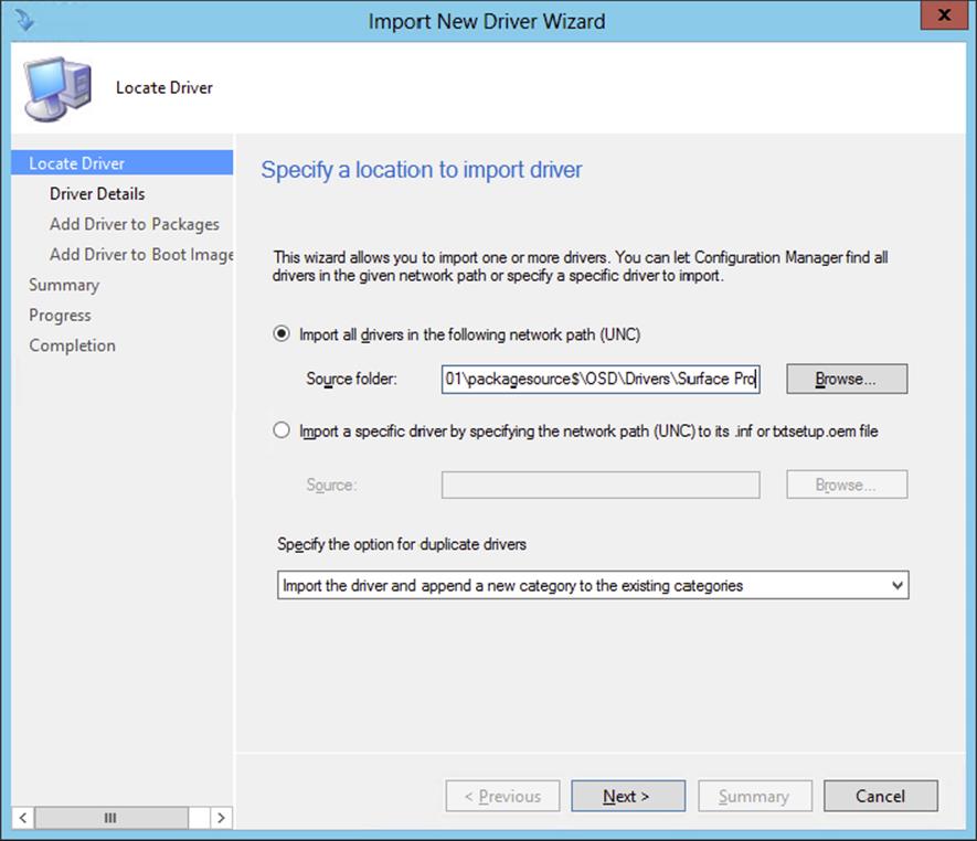
Figure 10.32 Import New Driver Wizard—Locate Driver page
3. You can specify to import all drivers or just a single device driver. When importing drivers you could run into the fact that there are duplicate drivers. Next, you should configure the import behavior when duplicate drivers are detected; you can configure the following options:
· Import the driver and append a new category to the existing categories.
· Import the driver and keep the existing categories.
· Import the driver and overwrite the existing categories.
· Do not import the driver.
4. Click Next after picking the correct driver(s), and then you will be presented with the Driver Details page. Next you should assign the driver(s) to one or more categories.
Working with Categories Enables You to Manage Drivers
If you add categories to drivers, you can manage your drivers in the store more easily. By adding the category to the search criteria, you can easily select the drivers and delete them by clicking Delete on the Home tab of the ribbon in the Configuration Manager console.
5. On the Add Driver To Packages page, shown in Figure 10.33, specify the package(s) you want to add this driver to, or specify a new package. If you need to create a new driver package, do the following.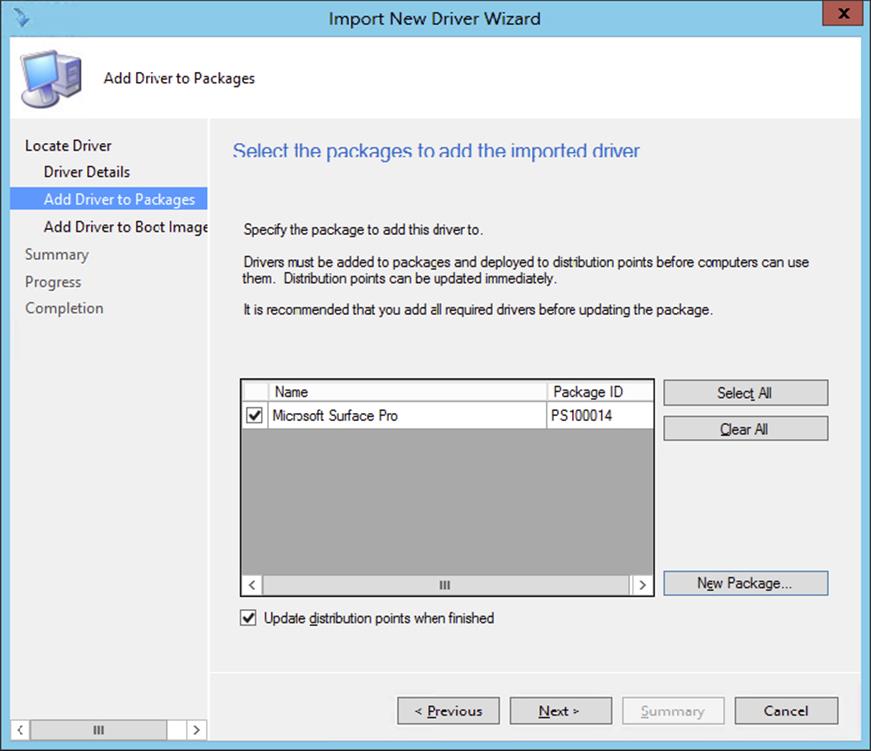
Figure 10.33 Import New Driver Wizard—Add Driver To Packages page
a. Click New Package.
b. Supply a name and a UNC path for the source of the package.
c. Click OK.
d. If desired, select Update Distribution Points When Finished so the driver will be available as soon as possible to your site.
6. Click Next to continue.
7. Next, select which boot images you want to add the driver to, as shown in Figure 10.34. When selecting drivers in bulk—for instance, all drivers from one model—do not add these to the boot images. Add them in a later stage. It is a best practice to add only the missing NIC drivers and drivers related to storage (controllers) to the boot images.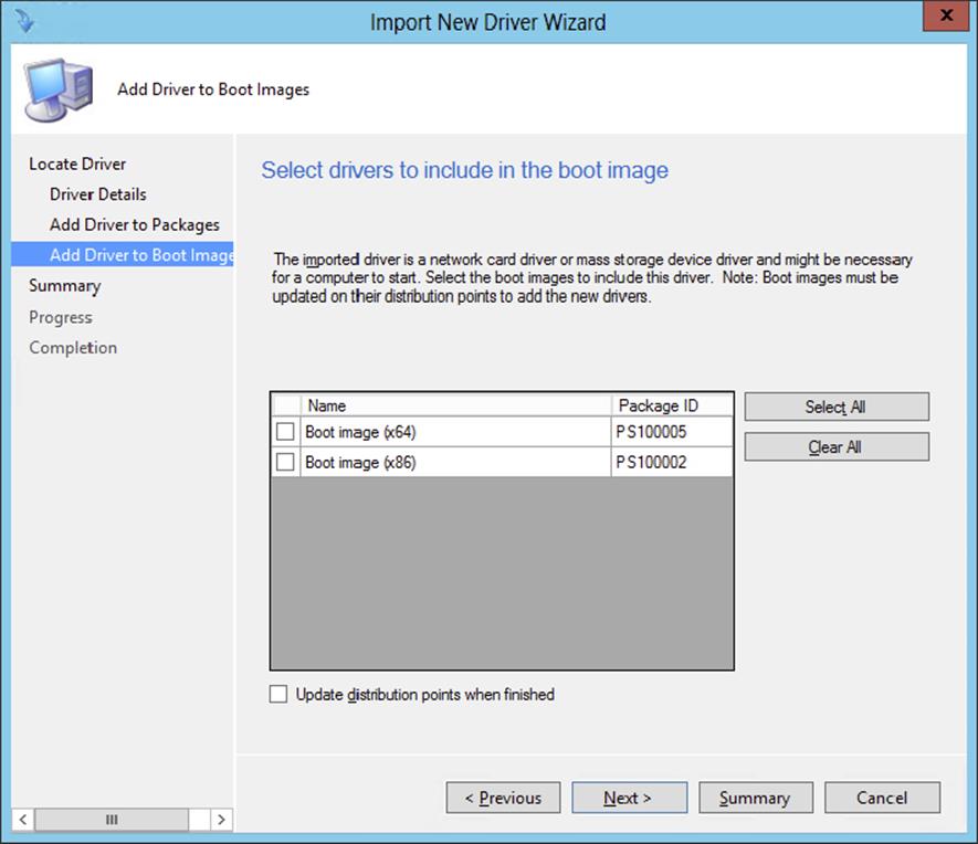
Figure 10.34 Adding drivers to boot images
8. Click Next to open the Summary page. Review the configuration, click Next, and then click Close.
Now Configuration Manager will inject that driver package into the packages and boot images you selected. This could take some time to process.
Using User Device Affinity
As discussed earlier, user device affinity enables you to deploy user-targeted applications during the operating system deployment process. There are several ways to configure user device affinity. Let’s look at the following options:
· Manually configure a primary user for a device.
· Manually configure a primary device for a user.
· Configure a site to automatically create user device affinities.
· Import user device affinities.
· Enable users to configure their primary device.
Manually Configure a Primary User for a Device
To manually configure a primary user for a device, follow this procedure:
1. From within the Configuration Manager console, choose the Assets and Compliance workspace, expand Overview, and select Devices.
2. Select a device, and click Edit Primary Users on the Home tab of the ribbon. Search for the user, as shown in Figure 10.35, select the user, and click Add and then OK to set the primary user for the device.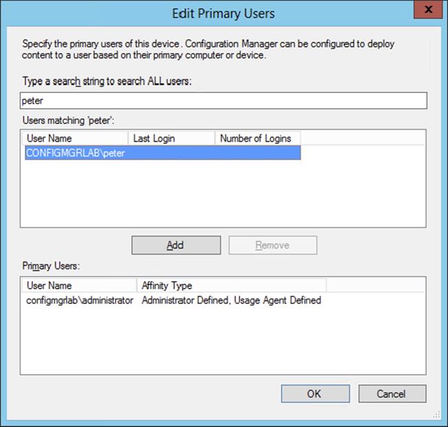
Figure 10.35 Search for and select the primary user
Manually Configure a Primary Device for a User
To manually configure a primary device for a user, follow these steps:
1. From within the Configuration Manager console, select the Assets And Compliance workspace, expand Overview, and select Users.
2. Select a user, and click Edit Primary Devices on the Home tab of the ribbon. Search for the device, select the device, and click Add and then OK to set the primary device for the user.
Configure a Site to Automatically Create User Device Affinities
With Configuration Manager 2012 you can also create the user device affinity automatically. Creating the affinity automatically is based on thresholds configured in the client settings. Configuring the client settings to create user device affinities is described here:
1. From within the Configuration Manager console, choose the Administration workspace, expand Overview, and select Client Settings.
2. Select the default client settings package or create a new client device agent settings package, and click Properties on the Home tab of the ribbon.
3. Select User And Device Affinity, as shown in Figure 10.36, and configure the following options.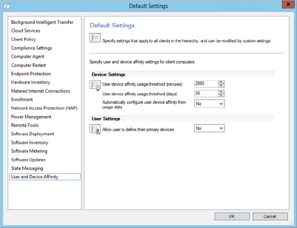
Figure 10.36 Configure client device settings.
1. User Device Affinity Usage Threshold (Minutes) Configure the number of minutes of usage by a user before a user device affinity is created.
2. User Device Affinity Usage Threshold (Days) Configure the number of days Configuration Manager will measure the usage of the device. For example, if User Device Affinity Usage Threshold (Minutes) is configured with a value of 120 minutes and User Device Affinity Usage Threshold (Days) is set to 14 days, the user must use the device for 120 minutes over a period of 14 days before the user device affinity is created.
3. Automatically Configure User Device Affinity From Usage Data Enable the feature by setting the value to Yes, or disable the feature by setting the value to No.
Import User Device Affinities
If you have the information from your client computers and primary users in a CSV file, you can import the user device affinity information to Configuration Manager 2012.
1. From within the Configuration Manager console, select the Assets And Compliance workspace, expand Overview, and select Devices or Users.
2. On the Home tab of the ribbon select Import User Device Affinity.
3. Browse and select the CSV file containing the information that you want to import, and click Open. The format of the CSV file must be <Domain\user name>,<Device NetBIOS name>. Select the option This File Has Column Headings For Reference Purposes if you have the following as the first line of the CSV file: users,devices.
4. Check in the File Preview section of the Choose Mapping page of the wizard to see if the column mapping is configured correctly, as shown in Figure 10.37, and click Next twice. Click Close after reviewing the results.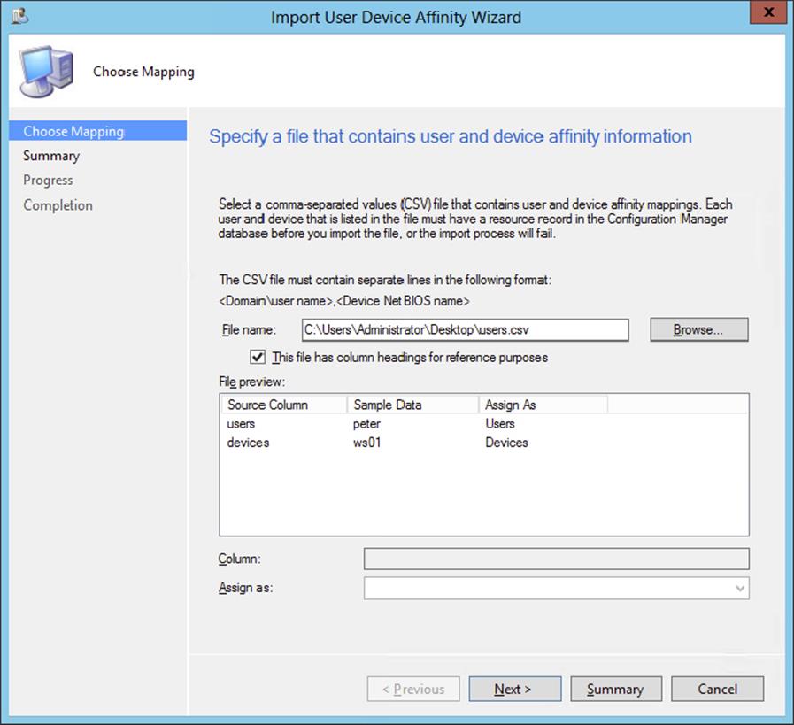
Figure 10.37 Check the column mapping.
Enable Users to Configure Their Primary Device
Another option is to configure the Configuration Manager 2012 site to let the users define their own user device affinities. This is done as follows:
1. From within the Configuration Manager console, select the Administration workspace, expand Overview, and select Client Settings.
2. Select the default client settings package or create a new client device user settings package. Then click Properties on the Home tab of the ribbon.
3. Select User And Device Affinity, and set the option Allow Users To Define Their Primary Devices to Yes. Setting the option to No will disable the feature.
From now on, the users can configure their user device affinity by selecting the I Regularly Use This Computer To Do My Work option in the My Devices tab of the Application Catalog website.
Pre-deploy User Applications
After configuring user device affinity for a client computer, the applications that are targeted to the primary user are pre-deployed automatically during deployment of the OS. Be sure to enable, while deploying the application to a user, the option Deploy Automatically According To Schedule With Or Without User Login, and set the Purpose to Required, as shown in Figure 10.38. You will find more information about deploying applications in Chapter 6, “Client Installation.”
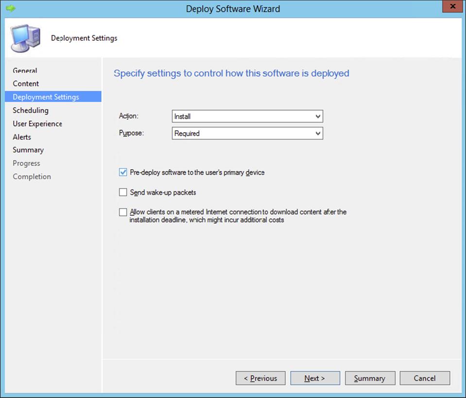
Figure 10.38 Configure deployment settings.
Deploying Windows To Go
Windows To Go is new for Window 8.x and gives you the ability to install your corporate domain-joined image from a USB-connected device. This can be a special USB stick or a special USB drive. To be able to install your corporate Windows 8.x image on the USB device, you need to follow these steps:
1. Create a task sequence for deploying Windows 8.x.
2. Create a prestaged media for the task sequence.
3. Create a Windows To Go creator package.
4. Update the task sequence to enable BitLocker.
5. Deploy the Windows To Go creator package and Windows 8.x task sequence.
Creating a Prestaged Media for the Task Sequence
Since you’ve already created a task sequence for deploying bare-metal computers, you can use it for the Windows To Go deployment.
1. From within the Configuration Manager console, select the Software Library workspace, expand Overview, expand Operating Systems, and select Task Sequences.
2. Click Create Task Sequence Media from the Home tab of the ribbon and select Prestaged Media in the Create Task Sequence Media Wizard; then select Allow Unattended Operating System Deployment. Click Next.
3. Select Site-Based Media, click Next, and specify information for the media file, as shown in Figure 10.39.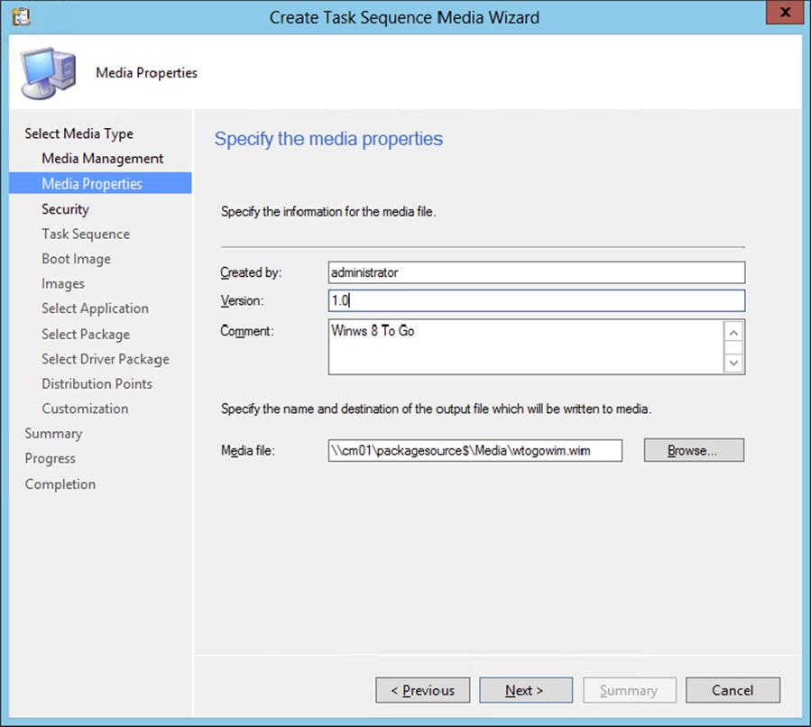
Figure 10.39 Create Task Sequence Media Wizard - Media Properties
4. Supply a media file to which the output is written and click Next.
5. Keep Enable Unknown Computer Support enabled and supply a strong password. Click Next.
6. Click Browse, select the Bare Metal Deployment task sequence created previously, and click Next.
7. On the Boot Image page, select a distribution point and management point that can be used by the boot media.
8. Select the distribution point on the Images page, and click Next.
9. Add an application that you want to install, as shown in Figure 10.40, and click Next.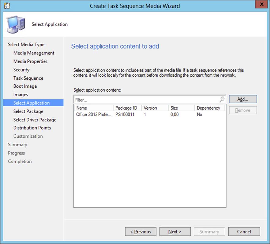
Figure 10.40 Create Task Sequence Media Wizard - Select Application
10.Add packages that you want to install and click Next.
11.Select driver packages that you need and click Next.
12.Select the distribution points you need and click Add. Click Next after adding the distribution points.
13.When enabling BitLocker on a Windows To Go device, you need a passphrase; this passphrase can be set with the variables in the Customization page of the wizard. Click the yellow starburst and add OSDBitLockerPIN as the name of the variable, as shown in Figure 10.41. Click OK and Next.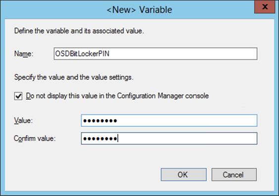
Figure 10.41 Add the OSDBitLockerPIN variable.
14.Review the Summary and click Next.
15.Click Close after the Create Task Sequence Media Wizard has completed successfully.
Creating a Windows To Go Creator Package
The next step in the process of creating a Windows To Go USB device is creating the Windows To Go creator package.
1. Copy the just-created WIM file to a folder in the package source share of your environment.
2. Copy the file wtgcreator.exe, which you can find in the \OSD\Tools\WTG\Creator folder in the program folder of your Configuration Manager 2012 installation, to the same folder in the package source share.
3. From within the Configuration Manager console, select the Software Library workspace, expand Overview, expand Application Management, and select Packages.
4. Click Create Package in the Home tab of the ribbon of the console. Supply a name, description, and manufacturer, and enable the This Package Contains Source Files option. Click Browse and browse to the just-created folder in the package source share with the WIM file and the wtgcreator.exe file. Click Next.
5. Select Standard Program and click Next. Supply a name and the command line that will provision the Windows To Go device. The command line must be in the format WTGCreator.exe /wim:<wimfile>.wim, as shown in Figure 10.42.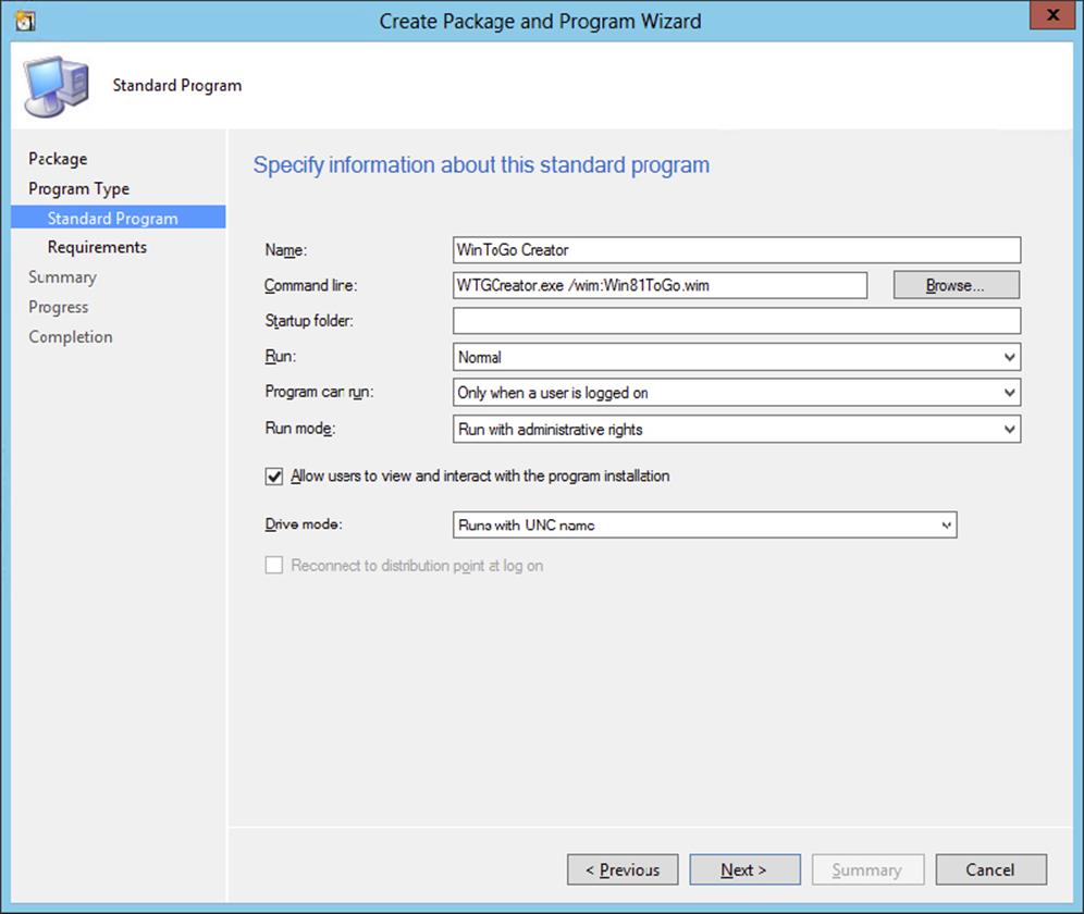
Figure 10.42 Create the Windows To Go Creator package.
6. Select Program Can Run Only When A User Is Logged On, and configure the run mode as Run With Administrative Rights. Select the option Allow Users To View And Interact With The Program Installation. Click Next.
7. Configure the requirements for the platform that can be used to provision the device. Click Next.
8. Review the summary, click Next, and click Close after processing the changes.
After creating the package, be sure to distribute the package to the distribution points and deploy it to a collection with users who are allowed to provision the Windows To Go devices.
Update the Task Sequence to Enable BitLocker
The next step is to enable BitLocker for the Windows To Go devices. To do this, you need to create a package for the utility that allows you to enable BitLocker, and you need to change the task sequence:
1. From within the Configuration Manager console, select the Software Library workspace, expand Overview, expand Application Management, and select Packages.
2. Click Create Package in the Home tab of the ribbon of the console. Supply a name, description, and manufacturer, and enable the This Package Contains Source Files option. Use as the source folder \OSD\Tools\WTG\BitLocker in the program folder of your Configuration Manager 2012 installation.
3. Select Do Not Create A Program and click Next, Next, and Close.
4. From within the Configuration Manager console, select the Software Library workspace, expand Overview, expand Operating Systems, and select Task Sequences.
5. Select the task sequence that you will use to provision the Windows To Go device and click Edit in the Home tab of the ribbon.
6. Select the Setup Windows And ConfigMgr task and click Add ⇒ General ⇒ Run Command Line.
7. Supply a name and command line that will provision the Windows To Go device. The command line must be in the format i386\osdbitlocker_wtg.exe/Enable/pwd:AD when using the 32-bit operating system or x64\osdbitlocker_wtg.exe/Enable/pwd:AD when using a 64-bit operating system. The /pwd parameter can either be None for not saving the BitLocker PIN or AD for storing the BitLocker PIN in Active Directory.
8. Enable the Package option, click Browse, and select the earlier-created BitLocker package, as shown in Figure 10.43.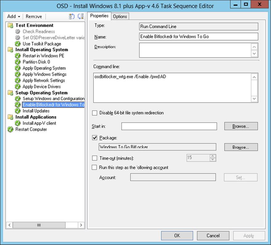
Figure 10.43 Edit the task sequence to enable BitLocker.
9. Click the Options tab of the BitLocker task in the task sequence and click Add Condition ⇒ Task Sequence Variable. Supply _SMSTSWTG as a variable, equals as the condition, and True as the value. Click OK.
10.Click OK after adding the condition.
Deploy the created task sequence to a collection with devices that can be used to provision Windows To Go.
Running the Windows To Go Package
The next step is to start the deployed Windows To Go creator package from a Windows workstation. By doing this, the Prestaged Media WIM file will be installed on the device that you will be using for Windows To Go.
1. Plug in the USB device and unlock it if necessary.
2. Go to the Software Center in the Start screen and install the Windows To Go creator package. After the Windows To Go creator software is started, you need to select the LUN on the device that has enough space to hold the Windows To Go installation, as shown in Figure 10.44. Click Next.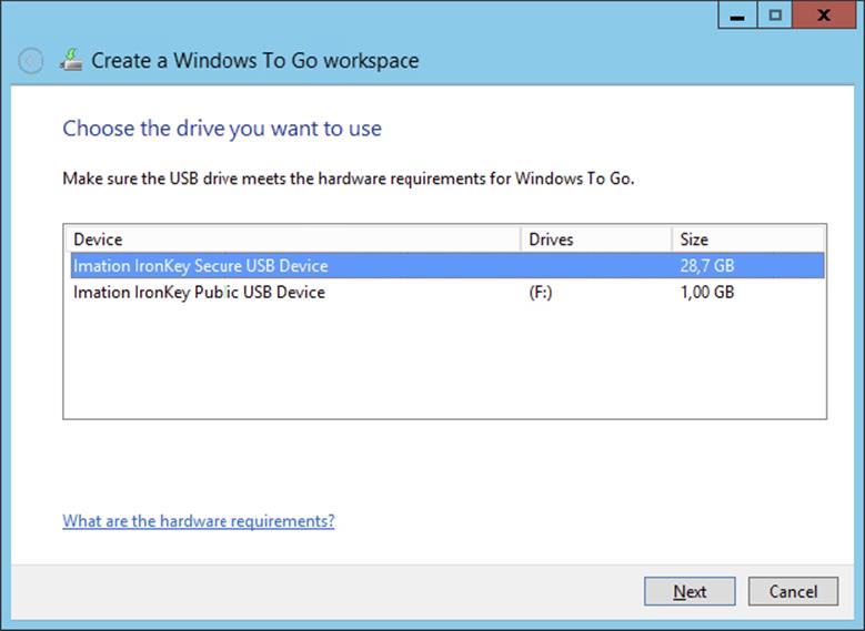
Figure 10.44 Select the LUN to deploy Windows To Go to.
3. Click Create to create the Windows To Go workspace, as shown in Figure 10.45. The created task sequence media will be used to provision, in this case, the Imation Ironkey W500.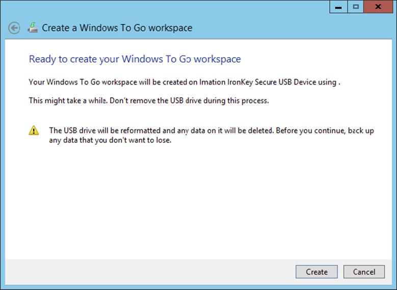
Figure 10.45 Click Create to create the Windows To Go workspace.
4. After the provisioning step is finished, click Finish.
The next step is to finish the installation of the Windows To Go workspace. You will need to boot from the Windows To Go USB device into the prestaged media environment and start the deployed Windows 8.1 task sequence. This will start the actual installation and configuration of Windows To Go on the USB device. When this process is finished, you are good to go.
Be Sure to Change the Boot Sequence
When provisioning the Windows To Go environment, you need to make sure that the workstation on which you are doing this is configured to boot first from your USB device. The workstation must restart several times during the installation of the Windows To Go workspace.
Microsoft Deployment Toolkit 2013
The Microsoft Deployment Toolkit 2013 is a solution accelerator that can be integrated with Configuration Manager 2012 R2. The integration gives you the ability to smooth your deployment process with the scripts that come with the Deployment Toolkit. Let’s configure the Microsoft Deployment Toolkit integration and see what it offers us when deploying operating systems.
The Microsoft Deployment Toolkit includes extra deployment scenarios that are built with a Task Sequence Wizard, such as the following:
1. Replace Hardware Scenario This scenario enables you to capture the user state from an old client computer and place it while deploying the new operating system on the new client computer.
2. Server Deployment Scenario This scenario allows you to deploy Windows-based servers and their roles.
3. User-Driven Installation Scenario This scenario allows your users to use a simple User Driven Installation (UDI) Wizard to initiate and customize an OS deployment on their PCs that’s tailored to their individual needs.
The wizard uses existing supporting packages like the boot image, the Microsoft Deployment Toolkit, or the User State Migration Package or allows you to create new packages while configuring the task sequence.
Installing Microsoft Deployment Toolkit 2013
The Microsoft Deployment Toolkit is a free tool that you can download from the Microsoft Download site. Install the MicrosoftDeploymentToolkit2013_x64.msi or MicrosoftDeploymentToolkit2013_x86.msi file on your site system. It’s a straightforward Next, Accept License Agreement, Next, Next, Next, Install, Finish installation. You need to install the Microsoft Deployment Toolkit on every site server that you want to integrate with.
Integrating the Deployment Toolkit
To be able to use the deployment intelligence of the Microsoft Deployment Toolkit in Configuration Manager 2012 R2, you need to integrate the Deployment Toolkit with Configuration Manager. This is done by following these steps:
1. After installing the Microsoft Deployment Toolkit 2013 on your site system, go to the Start screen.
2. Click Configure ConfigMgr Integration to start the integration tool.
3. Configure the integration as shown in Figure 10.46.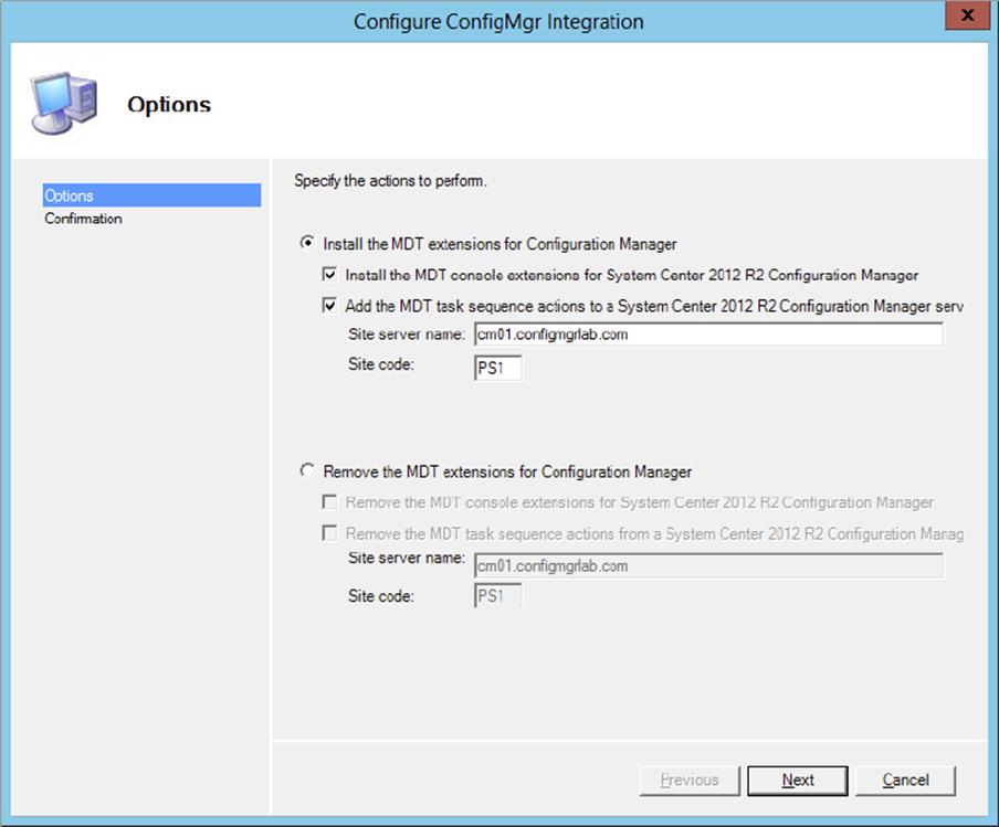
Figure 10.46 Configure the integration
4. Select Install The MDT Console Extensions For System Center 2012 R2 Configuration Manager and Add The MDT Task Sequence Actions To A System Center 2012 R2 Configuration Manager Server. Next, configure the Site Server Name and Site Code fields, and click Next.
5. Review the summary, and click Finish.
Creating a New Boot Image
This is an optional step since more and more extras of the Microsoft Deployment Toolkit are moving to native Configuration Manager features. Follow the next steps to re-create the Microsoft Deployment Toolkit boot images. You can also create a boot image with the Microsoft Deployment Toolkit integration features while creating a new Microsoft Deployment Toolkit task sequence. Create a boot image for both x86 and x64 platforms.
1. From within the Configuration Manager console, choose the Software Library workspace, expand Overview ⇒ Operating Systems, and select Boot Images.
2. Click Create Boot Image Using MDT on the Home tab of the ribbon, and supply the UNC path to the location where you want to store the boot image; click Next.
3. Supply a name, version, and comments, and click Next.
4. Select the platform for which you are creating the boot image, select the Scratch Space value from the dropdown list, as shown in Figure 10.47, and click Next. Scratch Space is a RAM drive that is used during OSD.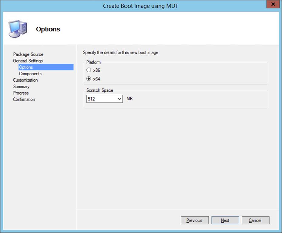
Figure 10.47 Configure the platform and scratch space.
5. Configure the optional languages and components like MDAC/AO support and PPPoE support and click Next.
6. Configure the customizations, such as the pre-execution hook, custom background image, and command support.
7. Click Next to review the summary.
8. Click Next after reviewing the summary, and click Finish after creating the custom boot image; this process can take a while.
9. Be sure to enable the boot image for PXE support and the deployment of the boot image to the distribution points.
Creating a Deployment Toolkit Task Sequence
After creating the optional Microsoft Deployment Toolkit boot images, you need to create a task sequence that you can use to deploy the operating system. In this example we will use the client replace scenario, which consists of two task sequences: the Client Replace task sequence and one based on the new computer scenario. The new computer scenario is like the bare-metal scenario, but we also use the User State Migration Toolkit to bring back the user state.
1. From within the Configuration Manager console, choose the Software Library workspace, expand Overview ⇒ Operating Systems, and select Task Sequences.
2. Click Create MDT Task Sequence on the Home tab of the ribbon, and select the Client Replace Task Sequence option. Then click Next.
3. Give the task sequence a name, supply comments, and click Next.
4. Select an existing boot image, or create a new boot image using the Create A New Boot Image Package option. Click Next.
The first time you create a Microsoft Deployment Toolkit task sequence, you will need to create a Microsoft Deployment Toolkit Files package.
5. Select this option and supply a package source folder, as shown in Figure 10.48.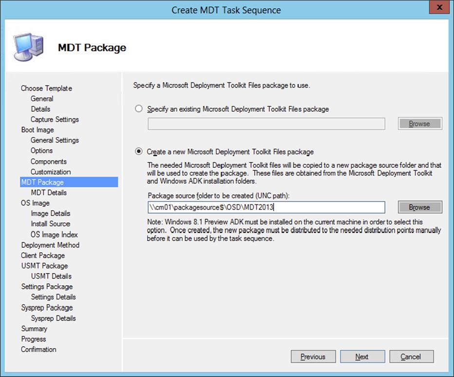
Figure 10.48 Create a new Microsoft Deployment Toolkit Files package.
The next time you create a Microsoft Deployment Toolkit task sequence, you can select the Microsoft Deployment Toolkit 2012 package.
6. Click Next.
7. Now you need to supply information about the package. Fill in the name, version language, and manufacturer, and click Next to proceed.
8. Select the User State Migration Tool package, and click Next.
9. Select Create A New Settings Package For This Operating System Deployment, supply the UNC path, and click Next.
10.Supply information about the package. Fill in the name, version language, and manufacturer, and click Next to proceed.
11.Review the summary and click Next. Click Finish after you’ve finished creating the packages and the task sequence.
After creating the Client Replace task sequence, you will need to create a task sequence based on the new computer scenario.
1. From within the Configuration Manager console, select the Software Library workspace, expand Overview ⇒ Operating Systems, and select Task Sequences.
2. Click Create MDT Task Sequence on the Home tab of the ribbon, and select the Client Task Sequence option. Then click Next.
3. Give the task sequence a name, supply comments, and click Next.
4. Supply the domain information, the account that has permissions to join the domain, and the Windows settings, and then click Next.
5. Select This Task Sequence Will Never Be Used To Capture An Image, and click Next.
6. Select an existing boot image, or create a new boot image using the Create A New Boot Image Package option. Click Next.
7. Select the Microsoft Deployment Toolkit 2012 package that you created earlier, and click Next.
8. Select the operating system image you want to deploy, as shown in Figure 10.49, and click Next.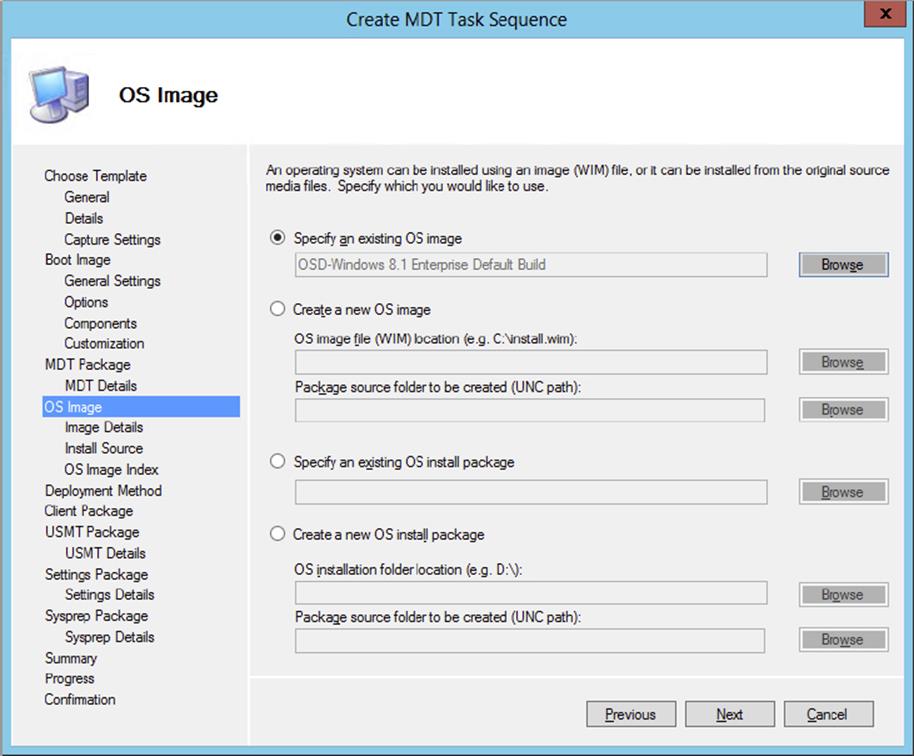
Figure 10.49 Select or create the operating system image you want to deploy.
9. Select Perform A “Zero Touch Installation” OS Deployment, With No User Interaction, and click Next.
10.Select the Configuration Manager Client 2012 package, and click Next.
11.Select the User State Migration Tool package, and click Next.
12.Select Create A New Settings Package For This Operating System Deployment, supply the UNC path, and click Next.
13.Supply information about the package. Fill in the name, version language, and manufacturer, and click Next to proceed.
14.Select No Sysprep Package Is Required, and click Next.
15.Review the summary, and click Next.
16.After the task sequence has been created, click Finish.
Using a Replace Scenario
The next step in creating a replace scenario for a computer is creating a computer association. This way the User State Migration Tool knows where to place the user state after installing the new computer.
1. From within the Configuration Manager console, select the Assets And Compliance workspace, and expand Overview ⇒ Devices.
2. Click Import Computer Information on the Home tab of the ribbon.
This will allow you to enter a single computer or import many systems from a comma-separated values (CSV) file.
3. Select the option Import Single Computer and click Next. This will bring up the Single Computer page.
You must enter the computer name along with either the MAC address or the SMBIOS GUID. The computer name is just how the machine will appear in the collections, not what the actual computer will be named.
4. Fill in the appropriate information, and select the source computer.
This creates an association with the old computer, and the User State Migration Tool knows where to get the user state.
5. After configuring, click Next.
6. On the Data Preview page, check the information and click Next.
7. Next, you’ll see the Choose Target Collection page. Here specify which collection you want to add to this new machine.
It is extremely valuable to put all the new computer installs into the same collection, which is used exclusively for new computer deployment.
8. Click Next.
9. After specifying the collection, you will see the Summary page. Review the information, click Next, and then click Close on the Finish page.
Next, you need to deploy the task sequences you just have created. The Client Replace task sequence must be deployed to a collection that is especially created for the old client computers. Then you need to deploy the New Computer task sequence to the collection that was specially created for the new computers. The deployment must support booting from PXE, as you learned in the “Deploying the Task Sequence” section earlier in this chapter.
Deploying a Virtual Hard Drive
With Configuration Manager 2012 you can deploy your images to a VHD that can be maintained by Configuration Manager and uploaded to a System Center 2012 R2 Virtual Machine Manager library. This is another example of the fact that Configuration Manager can be used to service the datacenter.
Deploying a virtual hard drive is done in two steps:
1. Create a VHD task sequence.
2. Create a virtual hard drive.
Creating a VHD Task Sequence
To be able to install an existing reference operation system image to a virtual hard drive, you need to create a special task sequence:
1. From within the Configuration Manager console, select the Software Library workspace, expand Overview ⇒ Operating Systems, and select Task Sequences.
2. Click Create Task Sequence on the Home tab of the ribbon, and select the option Install An Existing Image Package To A Virtual Hard Drive in the Create Task Sequence Wizard. Click Next.
3. Supply a name and description for the task sequence, and select a boot image that will support the operating system that you want to deploy. Click Next.
4. On the Install The Windows Operating System page, select the image package by browsing to the correct image. Supply a product key and be sure to enter a local administrator password.
5. On the Configure Network page, select the domain or workgroup to join.
If you select to join a domain, you can specify which OU to put the computer in once it joins the domain. You also will need to specify the account that has permission to join computers to a domain. The Configuration Manager Network Access account is often used to join the computer to the domain. You need to delegate this access to the user account. Verify the account by testing the connection after configuring the account.
6. Click Next to continue. On the Install Configuration Manager Client page, specify any additional installation properties. Click Browse if you do not want to use the default Configuration Manager 2012 client package.
7. Click Next to add applications to the task sequence. Click Next to review the summary.
8. After reviewing the summary, click Next and then Close to complete the creation of the task sequence. As always, be sure that all the related content is distributed to your distribution point (groups).
Creating a Virtual Hard Disk
The next step is creating the actual virtual hard disk. To do this, you need to run the Create Virtual Hard Disk Wizard from the Configuration Manager 2012 R2 console on a machine with the Hyper-V Role and Management console installed.
1. From within the Configuration Manager console, select the Software Library workspace, expand Overview ⇒ Operating Systems, and select Virtual Hard Disks.
2. Click Create Virtual Hard Disk on the Home tab of the ribbon. If this option is grayed out, you do not have the Hyper-V role or administrative tools installed.
3. Supply a name, version, comments, and a path to the VHD file, as shown in Figure 10.50; then click Next.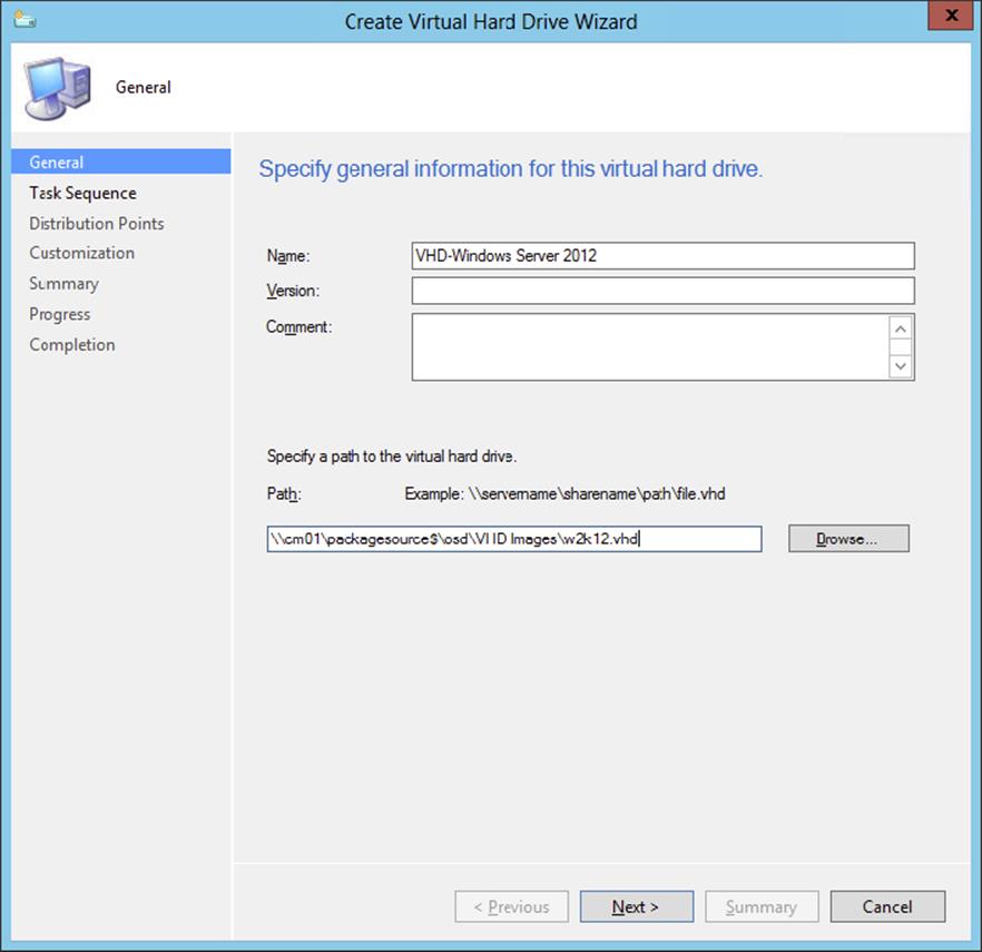
Figure 10.50 Specifying general information for the VHD
4. Select the task sequence created in the previous section and click Next.
5. Select the distribution point where all packages are available and click Add. Click Next to continue.
6. Add customizations for the task sequence if necessary and click Next.
7. Review the summary and click Next to start the VDH creation process, as shown in Figure 10.51.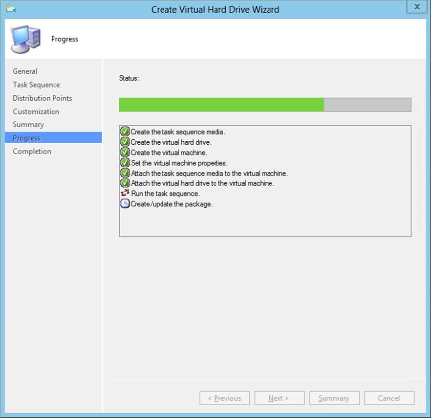
Figure 10.51 VHD creation process
In the backend, a virtual machine with the virtual hard disk is created in Hyper-V and the task sequence is started in this virtual machine. The virtual machine that it creates has a random name, as shown in Figure 10.52.
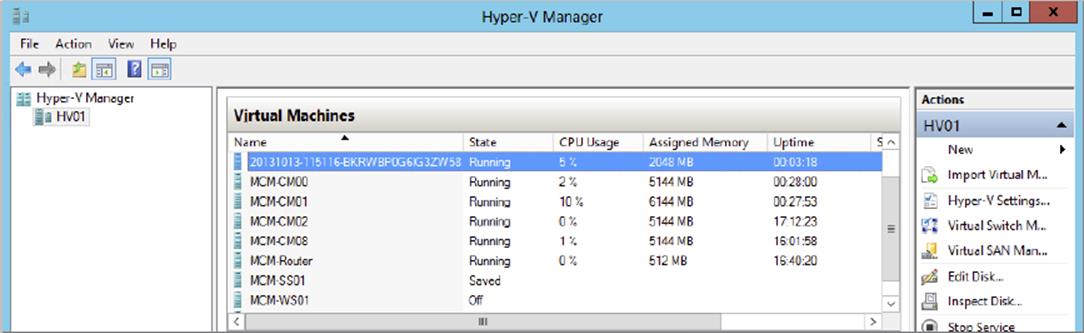
Figure 10.52 The created virtual machine in Hyper-V
After the task sequence is finished, the virtual machine will be deleted and the VHD file will be stored in the share that you have defined.
8. Click Close once the VHD is created.
Managing the Virtual Hard Disk
Now that you have a deployed virtual hard disk in your Configuration Manager 2012 R2 environment, you want to do something with it. There are several options; you can use it as an existing virtual hard disk in Hyper-V when creating a virtual machine manually or upload it in the System Center 2012 R2 Virtual Machine Manager library. Uploading the VHD is done as follows:
1. From within the Configuration Manager console, select the Software Library workspace, expand Overview ⇒ Operating Systems, and select Virtual Hard Disks.
2. Select the created virtual hard disk and click Upload To Virtual Machine Manager in the Home tab of the ribbon. You need to install the Virtual Machine Manager console to be able to upload the VHD.
3. Supply the VMM server name, select the VMM library share, and click Next. Review the summary, click Next, and click Close after completing the upload.
You can also modify the VHD from the Configuration Manager 2012 R2 console. For instance, here you can change the task sequence:
1. From within the Configuration Manager console, select the Software Library workspace, expand Overview ⇒ Operating Systems, and select Virtual Hard Disks.
2. Select the created virtual hard disk and click Modify Virtual Hard Disk. This kicks off the same wizard for creating the VHD, but you cannot change the path and name of the VHD, as shown in Figure 10.53.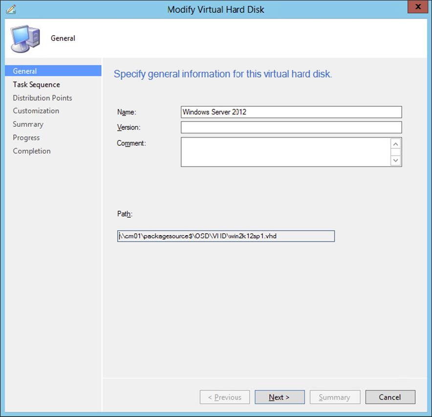
Figure 10.53 Modifying the virtual hard disk
Servicing Your Operating System Images and VHDs Offline
In Configuration Manager 2007 you needed a tool called Deployment Image Servicing and Management (DISM)—a command-line tool used to maintain and update your images offline. Configuration Manager 2012 R2 comes with the ability to update your operating system images from the console. This feature uses the software update point and software update deployments that you configured earlier. Follow these steps if you want to update a WIM image:
1. From within the Configuration Manager console, select the Software Library workspace, expand Overview ⇒ Operating Systems, and select Operating System Images.
2. Select the operating system you want to update, and click Schedule Updates on the Home tab of the ribbon.
3. Select the updates that you want to install in the Windows image, as shown in Figure 10.54, and click Next.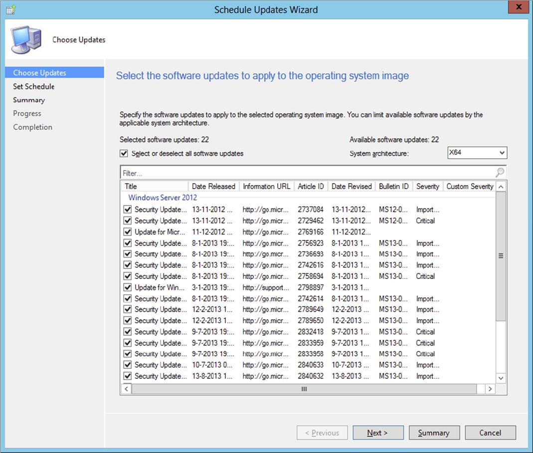
Figure 10.54 Select the updates that you want to install.
4. Select the schedule (as soon as possible or a custom schedule) for the update process, and click Next.
5. Review the summary, and click Next. Click Close when the process of scheduling the updates is finished.
The process of updating the Windows image can take a while; you can view the status of the process in the Scheduled Update Status column in the Configuration Manager console. Once the update is finished, you can see the installed updates in the console, as shown in Figure 10.55.
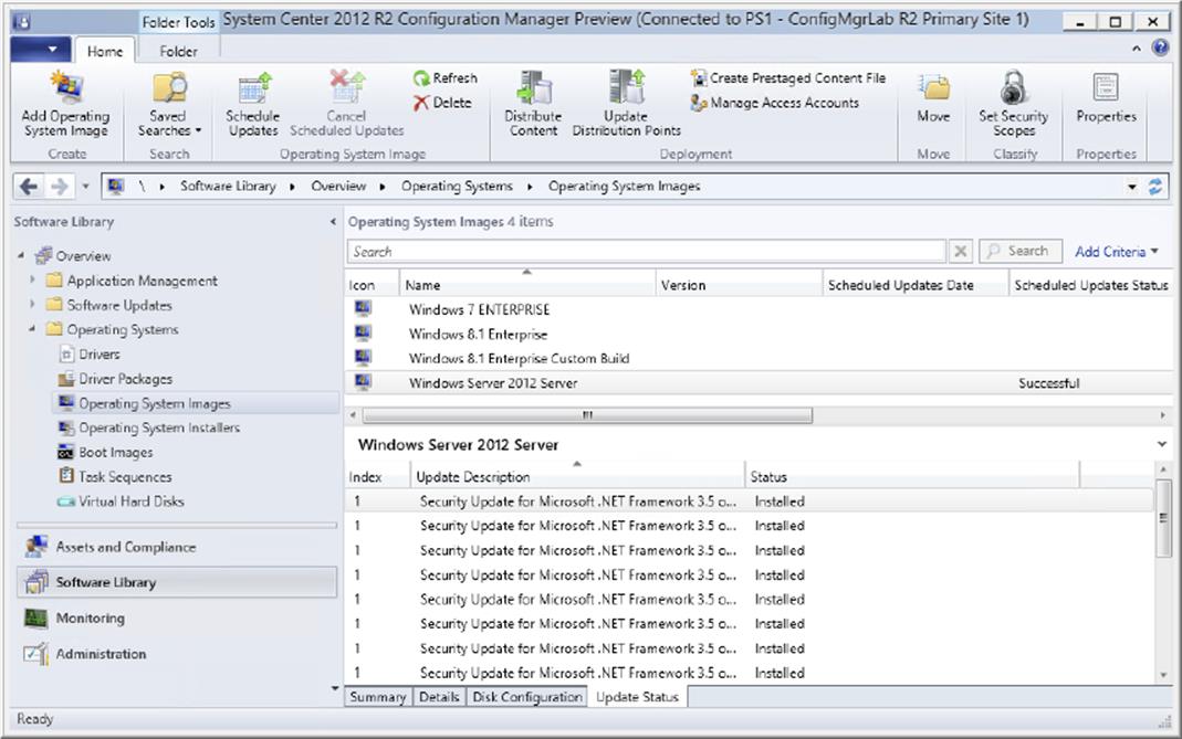
Figure 10.55 View the installed updates in the Windows image.
Besides installing software updates offline to operating system images, you can also schedule the installation of updates to virtual hard disks. The Schedule Updates wizard will walk you through the process.
Monitoring and Troubleshooting Offline Servicing
You can use the OfflineServicingMgr.log file in the logs folder of the Configuration Manager 2012 installation folder to monitor or troubleshoot while servicing your images offline.
You are also able to monitor the offline servicing by accessing the properties of the WIM image and viewing the Servicing tab, as shown in the following image. In addition, you can change the schedule if you have scheduled offline servicing.
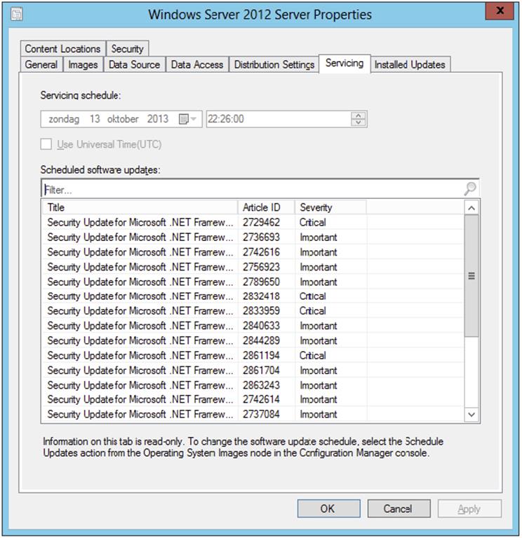
Support for Legacy Boot Images
Existing or manually created boot images based on Windows PE 3.1 can be added to Configuration Manager 2012 R2 to support the unattended installation of legacy operating systems like Windows XP or Windows 7. Configuration Manager 2012 R2 is able to distribute the boot images only to the distribution points; you cannot use Configuration Manager 2012 R2 to add drivers or make other changes to the Windows PE 3.1 boot images.
Walk through the following steps to create a custom Windows PE 3.1 boot image:
1. Download and install the Windows Automated Installation Kit (WAIK) 3.1 on a remote system.
2. Start the Deployment and Imaging Tools Environment from the Start menu or Start screen.
3. Create a folder named c:\winpe_x86 and start the command copype.cmd x86 c:\winpe-x86.
4. Copy and rename (to boot.wim) the default copied WinPE boot image to c:\winpe-x86\iso\sources with the following command: copy c:\winpe-x86\winpe.wim c:\winpe-x86\iso\sources\boot.wim.
5. Mount the boot.wim image so that you are able to make changes, and then dismount it with the following command: Dism /mount-wim /wimfile:C:\winpe-x86\ISO\sources\boot.wim /index:1 /MountDir:C:\winpe-x86\mount.
6. Now that the boot image is mounted and accessible through c:\winpe-x86\mount, you can modify it. You want to add WMI (WinPE-WMI), Scripting (WinPE-Scripting), and Windows Deployment Services (WinPE-WDS-Tools) support. Adding support is done as follows:
· Dism /image:C:\winpe-x86\mount /Add-Package /PackagePath:"C:\Program Files\Windows AIK\Tools\PETools\x86\WinPE_FPs\winpe-wmi.cab"
· Dism /image:C:\winpe-x86\mount /Add-Package /PackagePath: "C:\Program Files\Windows AIK\Tools\PETools\x86\WinPE_FPs\en-us\winpe-wmi_en-us.cab"
· dism /image:C:\winpe_x86\mount /Add-Package /PackagePath:"C:\Program Files\Windows AIK \Tools\PETools\x86\WinPE_FPs\winpe-scripting.cab"
· dism /image:C:\winpe-x86\mount /Add-Package /PackagePath:"C:\Program Files\Windows AIK \Tools\PETools\x86\WinPE_FPs\en-us\winpe-scripting_en-us.cab"
· dism /image:C:\winpe-x86\mount /Add-Package /PackagePath:"C:\Program Files\Windows AIK \Tools\PETools\x86\WinPE_FPs\winpe-WDS-Tools.cab"
· dism /image:C:\winpe-x86\mount /Add-Package /PackagePath:"C:\Program Files\Windows AIK \Tools\PETools\x86\WinPE_FPs\en-us\winpe- WDS-Tools_en-us.cab"
7. After making changes to the boot image, you need to commit those changes to the boot.wim file, this is done with the following command: Dism /unmount-Wim /MountDir:C:\winpe-x86\mount /Commit.
8. After committing the changes, you need to copy the boot image to your package source and import the boot image to Configuration Manager. You need to do the same for the x64 boot image. Use the imported images only for the task sequences that need the custom legacy boot images.
For a complete guide to creating custom boot images, see the TechNet article “Walkthrough: Create a Custom Windows PE Image”: http://technet.microsoft.com/en-us/library/dd744533(WS.10).aspx.
Maintaining the User State
When you browse to the User State Migration node in the Assets And Compliance workspace, as shown in Figure 10.56, you can manage computer associations. In this workspace you can create new computer associations, as mentioned earlier, see recovery information, find information about the user state migration, or specify the user accounts.
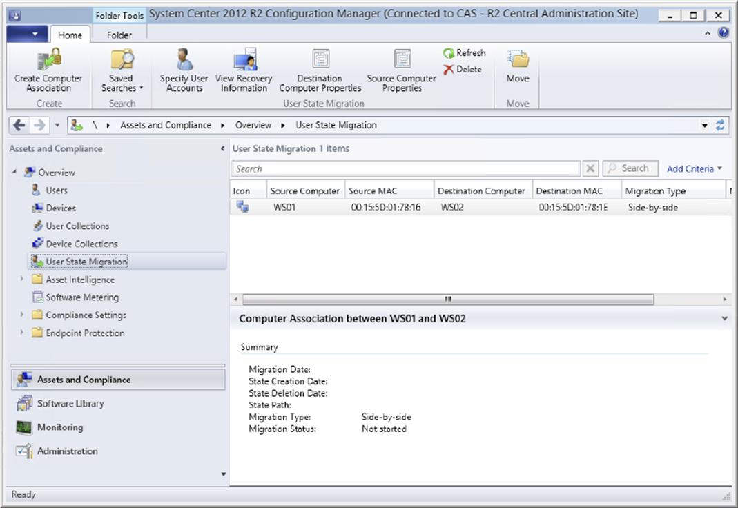
Figure 10.56 Managing the user state
Specifying the user accounts is done as follows:
1. From within the Configuration Manager console, choose the Assets And Compliance workspace and expand Overview ⇒ User State Migration.
2. Select the User State Migration item, and click Specify User Accounts to add user accounts for which data needs to be migrated.
3. Click the starburst icon, and on the Add User Account screen click Browse. Search for the user and click OK twice.
4. Click OK to set the user account to migrate.
From this view you can also create computer associations when, for instance, migrating user state data from one computer to an existing computer that is being reinstalled.
![]()
Assigning Many Computers to the Bare-Metal Deployment
George T. Management sends an email to the help desk stating that his department just ordered 10 new machines with no operating system and that he wants them all configured by the end of the day with the same image that was used on his machine. The list of 10 machines was included in the email.
You meet with your Configuration Manager team and decide that the best way to do this is to use Configuration Manager to push the image out using the PXE service point that has already been used in the environment.
So, you open the Configuration Manager console, choose the Assets And Compliance workspace, expand Overview ⇒ Devices, and click Import Computer Information on the Home tab of the ribbon. On the Import Computer Information page, you select Import Computers Using A File, and click Next. On the Choose Mappings page, you click Browse to browse the comma-separated file that Mr. Management sent you containing the list of computers on which you need to deploy the new operating system.
After you import the file and assign the data mappings, you click Next. Then you verify that the data is correct on the Data Preview page and add these systems into the bare-metal collection created earlier with the Windows 7 build already assigned. Finally, you click Finish to add the members to the collection. Configuration Manager will then deploy the new operating system when the machines are powered on and booted up in PXE boot.
The Bottom Line
1. Specify a Network Access account. The Network Access account is the account Configuration Manager will use to access the system while running WinPE.
1. Master It How do you specify the Network Access account?
2. Enable PXE support. PXE support in Configuration Manager is used to begin the operating system deployment process. The PXE feature responds to Configuration Manager clients making PXE boot requests.
1. Master It How do you set up PXE support?
3. Update the driver catalog package. The driver catalog allows you to add drivers to the already created packages and images you have within your organization so you are not constantly re-creating your images when you get a new machine in your environment.
1. Master It How do you update the driver catalog package?
4. Update an image from the console. In the past it was a big issue to keep your images up to date; no easy procedure existed. In Configuration Manager 2012 a feature called Schedule Updates exists to update your Windows images.
1. Master It How do you update your Windows images?
All materials on the site are licensed Creative Commons Attribution-Sharealike 3.0 Unported CC BY-SA 3.0 & GNU Free Documentation License (GFDL)
If you are the copyright holder of any material contained on our site and intend to remove it, please contact our site administrator for approval.
© 2016-2026 All site design rights belong to S.Y.A.