CCNA Wireless 200-355 Official Cert Guide (2016)
Chapter 10. Implementing Controller-based Deployments
This chapter covers the following topics:
![]() Connecting a Centralized Controller—This section describes the controller ports and interfaces and explains how the controller is connected to the network.
Connecting a Centralized Controller—This section describes the controller ports and interfaces and explains how the controller is connected to the network.
![]() Performing an Initial Setup—This section covers how to provide a bootstrap configuration to a new controller. Both web-based and command-line interface methods of configuration are explored.
Performing an Initial Setup—This section covers how to provide a bootstrap configuration to a new controller. Both web-based and command-line interface methods of configuration are explored.
![]() Maintaining a Wireless Controller—This section explains how to back up the controller configuration and how to upgrade the software image.
Maintaining a Wireless Controller—This section explains how to back up the controller configuration and how to upgrade the software image.
This chapter covers the following exam topics:
![]() 3.2—Describe physical infrastructure connections
3.2—Describe physical infrastructure connections
![]() 3.2a—Wired infrastructures (AP, WLC, access/trunk ports, LAG)
3.2a—Wired infrastructures (AP, WLC, access/trunk ports, LAG)
![]() 3.3—Describe AP and WLC management access connections
3.3—Describe AP and WLC management access connections
![]() 3.3.a—Management connections (Telnet, SSH, HTTP, HTTPS, console)
3.3.a—Management connections (Telnet, SSH, HTTP, HTTPS, console)
![]() 3.3.b—IP addressing: IPv4/IPv6
3.3.b—IP addressing: IPv4/IPv6
![]() 4.1—Execute initial setup procedures Cisco wireless infrastructures
4.1—Execute initial setup procedures Cisco wireless infrastructures
![]() 4.1b—Converged
4.1b—Converged
![]() 4.1c—Centralized
4.1c—Centralized
![]() 4.5—Identify wireless network and client management and configuration platform options
4.5—Identify wireless network and client management and configuration platform options
![]() 4.5.a—Controller GUI and CLI
4.5.a—Controller GUI and CLI
![]() 4.6—Maintain wireless network
4.6—Maintain wireless network
![]() 4.6a—Perform controller configuration backups
4.6a—Perform controller configuration backups
![]() 4.6b—Perform code updates on controller, APs, and converged access switches
4.6b—Perform code updates on controller, APs, and converged access switches
![]() 4.6b(i)—AireOS: boot loader (FUS), image
4.6b(i)—AireOS: boot loader (FUS), image
![]() 4.6b(ii)—IOS-XE: bundle, unbundle
4.6b(ii)—IOS-XE: bundle, unbundle
Before you can use a Cisco wireless LAN controller, you must connect it to the switched network. The controller must also link wired networks with wireless ones. You need to understand how to make the necessary connections, both physical and logical, to build a functioning centralized wireless network. The initial deployment of a converged wireless network is simpler because the wireless LAN controller (WLC) is already embedded in the wired network as a part of a Catalyst switch.
This chapter covers the initial deployment concepts needed to connect and initially configure a controller so that you can manage it more fully.
“Do I Know This Already?” Quiz
The “Do I Know This Already?” quiz allows you to assess whether you should read this entire chapter thoroughly or jump to the “Exam Preparation Tasks” section. If you are in doubt about your answers to these questions or your own assessment of your knowledge of the topics, read the entire chapter. Table 10-1 lists the major headings in this chapter and their corresponding “Do I Know This Already?” quiz questions. You can find the answers in Appendix A, “Answers to the ‘Do I Know This Already?’ Quizzes.”
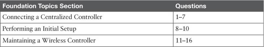
Table 10-1 “Do I Know This Already?” Section-to-Question Mapping
Caution
The goal of self-assessment is to gauge your mastery of the topics in this chapter. If you do not know the answer to a question or are only partially sure of the answer, you should mark that question as wrong for purposes of the self-assessment. Giving yourself credit for an answer you correctly guess skews your self-assessment results and might provide you with a false sense of security.
1. A wireless controller port is used for which one of the following purposes?
a. Construct CAPWAP tunnel packets
b. Provide a physical connection to a switch port
c. Create a logical connection to a WLAN
d. Provide a physical connection to an AP
2. Which one of the following is used for remote out-of-band management of a controller and the initial controller setup?
a. Distribution system port
b. Virtual interface
c. Service port
d. AP-manager interface
3. A distribution system port is usually configured in which one of the following modes?
a. 802.1Q trunk
b. Access mode
c. LACP trunk negotiation
d. Recovery mode
4. Which one of the following correctly describes the single logical link formed by bundling all of a controller’s distribution system ports together?
a. PHY
b. DSP
c. LAG
d. GEC
5. A CAPWAP tunnel terminates on which one of the following controller interfaces?
a. Virtual interface
b. Dynamic interface
c. Service port interface
d. AP-manager interface
6. Which one of the following is used to relay DHCP requests from wireless clients?
a. Management interface
b. Dynamic interface
c. Virtual interface
d. Service port interface
7. Which one of the following controller interfaces maps a WLAN to a VLAN?
a. Bridge interface
b. Virtual interface
c. WLAN interface
d. Dynamic interface
8. Suppose that you have just powered up a new controller. If you connect to the controller’s console port, in which one of the following modes will you find the controller?
a. Initial setup mode
b. ROMMON mode
c. Discovery mode
d. Promiscuous mode
9. Which of the following methods can you use to perform the initial setup of a wireless LAN controller? (Choose all that apply.)
a. CLI
b. TFTP
c. FTP
d. Web browser
10. To perform an initial configuration of a converged wireless controller, to which one of the following should you connect with your web browser?
a. Virtual interface
b. Console port
c. Dynamic interface
d. Access switch management address
11. Suppose you use a web browser to access a controller and make a configuration change. You make sure to click on the Apply button. A short time later, the controller loses power and then reboots. Which two of the following answers correctly describes the result?
a. The Apply button saved the change permanently
b. The Apply button made the change active, but didn’t save it across the reboot
c. You would need to click the Save Configuration link to save the change permanently
d. To save the change permanently, you would need to use the copy run start command from the CLI
12. To save a copy of a controller’s configuration, which of the following methods could you use?
a. Use Commands > Upload File
b. Use Commands > Download File
c. Use Commands > Configuration > TFTP
d. Use Commands > Files > Save Configuration
13. A centralized wireless LAN controller maintains how many code image files?
a. 1
b. 2
c. 3
d. Unlimited
14. Which two of the following file transfer methods can be used to move a centralized controller code image file onto a controller?
a. TFTP
b. RCP
c. SSH
d. FTP
e. XMODEM
f. HTTP
15. Suppose you need to transfer a code image file from a TFTP server on your PC to a controller. Which of the following file copy directions should you choose?
a. Download
b. Upload
c. None of the above; a controller automatically gets its image from WCS/NCS/PI
d. None of the above; it isn’t possible to transfer an image file via TFTP
16. After copying a new code image file to a controller, how should you copy the same code release to the lightweight APs?
a. Use Commands > Download to APs
b. Connect to each AP and copy the file there
c. Put the address of a TFTP server in the DHCP options field
d. Do nothing; each AP will get the new image as it rejoins the controller
Foundation Topics
Connecting a Centralized Controller
Cisco wireless LAN controllers partner with lightweight access points (LAPs) to provide connectivity between a wired network and mobile wireless clients. The wired network infrastructure also transports the packets that make up the Control and Provisioning of Wireless Access Points (CAPWAP) tunnels between the controllers and the access points (APs). Your first task to begin using a controller is to connect it to the network. From your work with Cisco routers and switches, you probably know that the terms interface and port are usually interchangeable. For example, switches can come in 24- or 48-port models, and you apply configuration changes to the corresponding interfaces. Cisco wireless controllers differ a bit; ports and interfaces refer to different concepts.
Controller ports are physical connections made to an external wired or switched network, whereas interfaces are logical connections made internally within the controller. The following sections explain each connection type in more detail.
Using Controller Ports
You can connect several different types of controller ports to your network, as shown in Figure 10-1 and discussed in the following list:
![]()
![]() Service port—Used for out-of-band management, system recovery, and initial boot functions; always connects to a switch port in access mode
Service port—Used for out-of-band management, system recovery, and initial boot functions; always connects to a switch port in access mode
![]() Distribution system port—Used for all normal AP and management traffic; usually connects to a switch port in 802.1Q trunk mode
Distribution system port—Used for all normal AP and management traffic; usually connects to a switch port in 802.1Q trunk mode
![]() Console port—Used for out-of-band management, system recovery, and initial boot functions; asynchronous connection to a terminal emulator (9600 baud, 8 data bits, 1 stop bit, by default)
Console port—Used for out-of-band management, system recovery, and initial boot functions; asynchronous connection to a terminal emulator (9600 baud, 8 data bits, 1 stop bit, by default)
![]() Redundancy port—Used to connect to a peer controller for redundant operation
Redundancy port—Used to connect to a peer controller for redundant operation
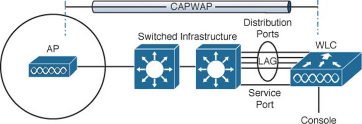
Figure 10-1 Cisco Wireless LAN Controller Ports
Controllers can have a single service port that must be connected to a switched network. Usually the service port is assigned to a management VLAN so that you can access the controller with Secure Shell (SSH) or a web browser to perform initial configuration or for maintenance. Notice that the service port supports only a single VLAN, so the corresponding switch port must be configured for access mode only.
Controllers also have multiple distribution system ports that you must connect to the network. These ports carry most of the data coming to and going from the controller. For example, the CAPWAP tunnels (control and data) that connect to each of a controller’s APs pass across the distribution system ports. Client data also passes from wireless LANs to wired VLANs over the ports. In addition, any management traffic using a web browser, SSH, Simple Network Management Protocol (SNMP), or Trivial File Transfer Protocol (TFTP) normally reaches the controller through the ports.
Because the distribution system ports must carry data that is associated with many different VLANs, VLAN tags and numbers become very important. For that reason, the distribution system ports always operate in 802.1Q trunking mode. When you connect the ports to a switch, you should also configure the switch ports for unconditional 802.1Q trunk mode.
The distribution system ports can operate independently, each one transporting multiple VLANs to a unique group of internal controller interfaces. For resiliency, you can configure distribution system ports in redundant pairs. One port is primarily used; if it fails, a backup port is used instead.
To get the most use out of each distribution system port, you can configure all of them to operate as a single logical group, much like an EtherChannel on a switch. Controller distribution system ports can be configured as a link aggregation group (LAG) such that they are bundled together to act as one larger link. In Figure 10-1, the four distribution system ports are configured as a LAG. With a LAG configuration, traffic can be load balanced across the individual ports that make up the LAG. In addition, LAG offers resiliency; if one individual port fails, traffic will be redirected to the remaining working ports instead.
Table 10-2 lists common Cisco controller models along with the distribution system and service ports available. As you might expect, the more APs a controller platform supports, the greater distribution system port throughput it needs. In contrast, almost every model uses a 1-Gbps service port because the out-of-band management traffic requirements are fairly small.
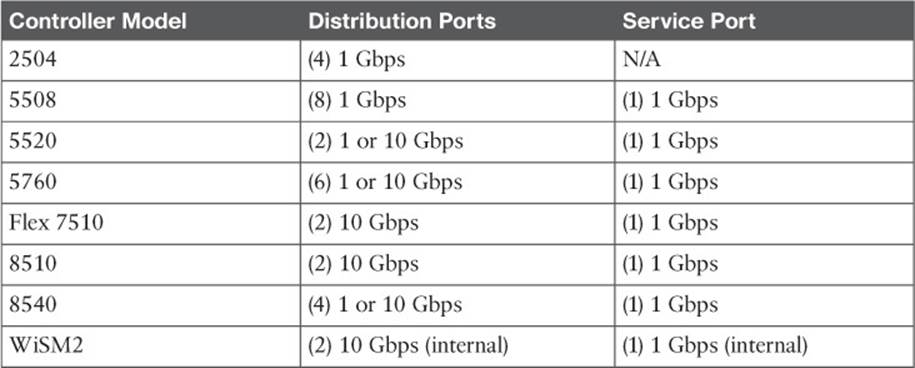
Table 10-2 Cisco Controller Models and Supported Distribution and Service Ports
Using Controller Interfaces
Through its distribution system ports, a controller connects to multiple VLANs on the switched network. Internally, the controller must somehow map those wired VLANs to equivalent logical wireless networks. For example, suppose that VLAN 10 is set aside for wireless users in the Engineering division of a company. That VLAN must be connected to a unique wireless LAN that exists on a controller and its associated APs. The wireless LAN must then be connected to every client that associates with service set identifier (SSID) “Engineering.”
Cisco wireless controllers provide the necessary connectivity through internal interfaces. A controller interface is logical and must be configured with an IP address, subnet mask, default gateway, and a Dynamic Host Configuration Protocol (DHCP) server. Each interface is then assigned to a physical port and a VLAN ID. You can think of an interface as a Layer 3 termination on a VLAN.
Cisco controllers support the following interface types, also shown in Figure 10-2:
![]()
![]() Management interface—Used for normal management traffic, such as RADIUS user authentication, WLC-to-WLC communication, web-based and SSH sessions, SNMP, Network Time Protocol (NTP), syslog, and so on.
Management interface—Used for normal management traffic, such as RADIUS user authentication, WLC-to-WLC communication, web-based and SSH sessions, SNMP, Network Time Protocol (NTP), syslog, and so on.

Figure 10-2 Cisco Wireless LAN Controller Interfaces
![]() AP-manager interface—A dynamic interface used to terminate CAPWAP tunnels between the controller and its APs. If no AP-manager interface is created, the function is performed by the manager interface instead.
AP-manager interface—A dynamic interface used to terminate CAPWAP tunnels between the controller and its APs. If no AP-manager interface is created, the function is performed by the manager interface instead.
![]() Virtual interface—IP address facing wireless clients when the controller is relaying client DHCP requests, performing client web authentication, and supporting client mobility.
Virtual interface—IP address facing wireless clients when the controller is relaying client DHCP requests, performing client web authentication, and supporting client mobility.
![]() Service port interface—Bound to the service port and used for out-of-band management.
Service port interface—Bound to the service port and used for out-of-band management.
![]() Dynamic interface—Used to connect a VLAN to a WLAN.
Dynamic interface—Used to connect a VLAN to a WLAN.
The management interface faces the switched network, where management users and APs are located. Management traffic will usually consist of protocols like HTTPS, SSH, SNMP, NTP, TFTP, and so on. In addition, management interface traffic consists of CAPWAP packets that carry control and data tunnels to and from the APs.
The virtual interface is used only for certain client-facing operations. For example, when a wireless client issues a DHCP request to obtain an IP address, the controller can relay the request on to a normal DHCP server. From the client’s perspective, the DHCP server appears to be the controller’s virtual interface address. Clients may see the virtual interface’s address, but that address is never used when the controller communicates with other devices on the switched network.
Because the virtual interface is used only for some client management functions, you should configure it with a unique, nonroutable address. For example, you might use 10.1.1.1 because it is within a private address space defined in RFC 1918.
Tip
Traditionally, many people have assigned IP address 1.1.1.1 to the virtual interface. Although it is a unique address, it is routable and already in use elsewhere on the Internet. A better practice is to use an IP address from the RFC 1918 private address space that is unused or reserved, such as 192.168.1.1. You could also use a reserved address from RFC 5737 (192.0.2.0/24) that is set aside for documentation purposes and is never used.
The virtual interface address is also used to support client mobility. For that reason, every controller that exists in the same mobility group should be configured with a virtual address that is identical to the others. By using one common virtual address, all the controllers will appear to operate as a cluster as clients roam from controller to controller.
Dynamic interfaces map WLANs to VLANs, making the logical connections between wireless and wired networks. You will configure one dynamic interface for each wireless LAN that is offered by the controller’s APs, and then map the interface to the WLAN. Each dynamic interface must also be configured with its own IP address and can act as a DHCP relay for wireless clients. To filter traffic passing through a dynamic interface, you can configure an optional access list. Dynamic interface and WLAN configuration are covered in more detail in Chapter 15, “Configuring a WLAN.”
Performing an Initial Setup
When you power up a wireless controller for the first time, it comes up with a minimal default configuration. The distribution system ports are not yet usable, but you can connect to the controller through its console port or through its service port—provided you have connected the service port to a switch or an Ethernet crossover cable. The service port can use a default IP address of 192.168.1.1, or it can request an address through DHCP.
The default configuration has no interfaces or WLANs defined. APs cannot connect to it until you provide some initial setup information and then configure it further after the controller reboots into normal operation.
You can use either a web browser or the command-line interface (CLI) to set up a controller for the first time. Depending on the model and code release running, the WLC could present one of two web-based initial configuration procedures: the initial Configuration Wizard (centralized and converged controllers) or the WLAN Express Setup. All of these methods are covered in the following sections. Through the initial setup, you define the minimum parameters for the controller to become operational—the service port, management interface, virtual interface, WLAN, authentication server, clock, and so on.
Initial Setup of a Centralized Controller with the Configuration Wizard
After you have connected a controller to the network and have powered it up, you can use a web browser to enter a basic configuration. The controller prompts you through the following sequence of steps to configure various parameters as part of the Configuration Wizard:
Step 1. Configure system access.
Connect your PC to the same VLAN and subnet that the controller’s service port uses, and then open a web browser to the controller’s service port IP address. In Figure 10-3, the service port uses 192.168.1.1 and the Configuration Wizard asks for a system name for the controller, along with an administrative user’s ID and password. By default, the username is admin and the password is admin. The system name is somewhat like a hostname and is used to identify the controller to APs and other controllers. Click the Next button to continue.
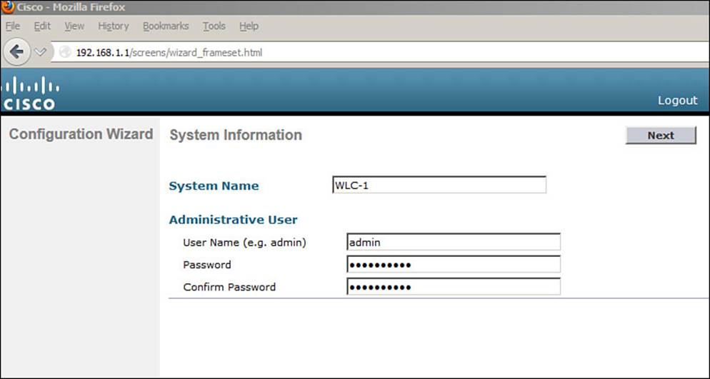
Figure 10-3 Starting the Configuration Wizard
Step 2. Configure SNMP access.
By default, SNMP Versions 2c and 3 are enabled. Version 3 provides the most secure access and is recommended, whereas Version 2c is not. Version 1 is disabled because it is not considered to be secure. You can enable or disable each version as shown in Figure 10-4. If SNMPv3 is enabled, the controller will remind you to configure an SNMPv3 user once the initial configuration is complete and the controller reboots. Click Next to continue.
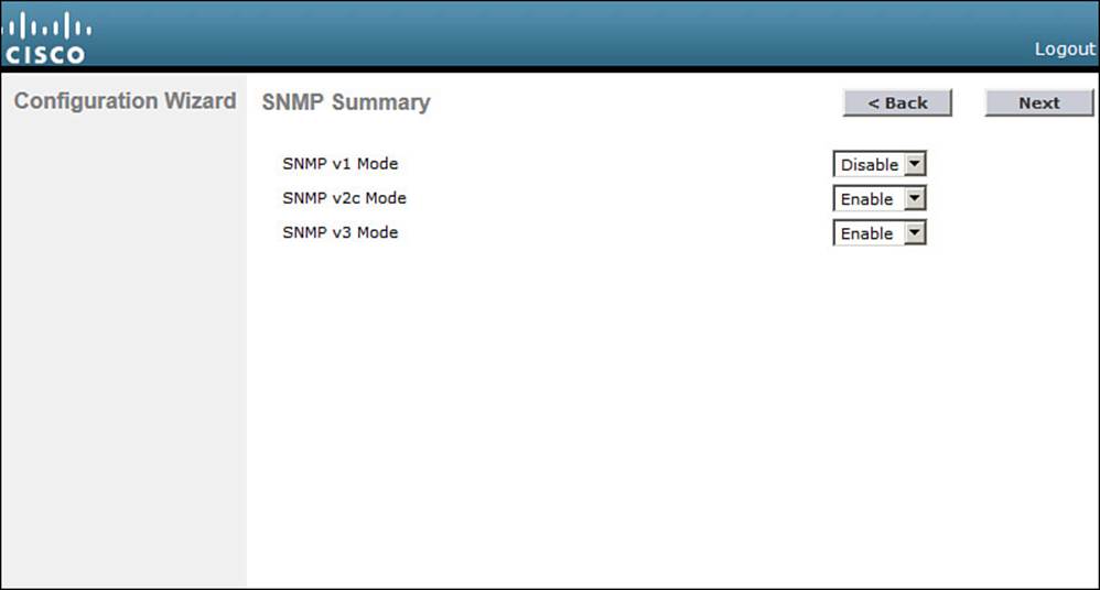
Figure 10-4 Configuring SNMP Access
Step 3. Configure the service port.
Although the controller’s service port has a default initial IP address (the one you’re using to run the initial configuration), you can configure it to use something else in the future. Check the DHCP Protocol box to have the controller request an address through DHCP. Otherwise, you can leave the box unchecked and enter a static IP address instead. In Figure 10-5, the service port is configured to use DHCP. The address and netmask shown will be disregarded. Click Next to continue.
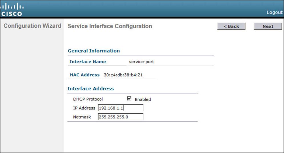
Figure 10-5 Configuring the Service Port
Step 4. Configure LAG mode.
By default, all the distribution system ports will be bundled together as a single LAG link, as shown in Figure 10-6. You can disable LAG mode through the drop-down menu. Click Next to continue.
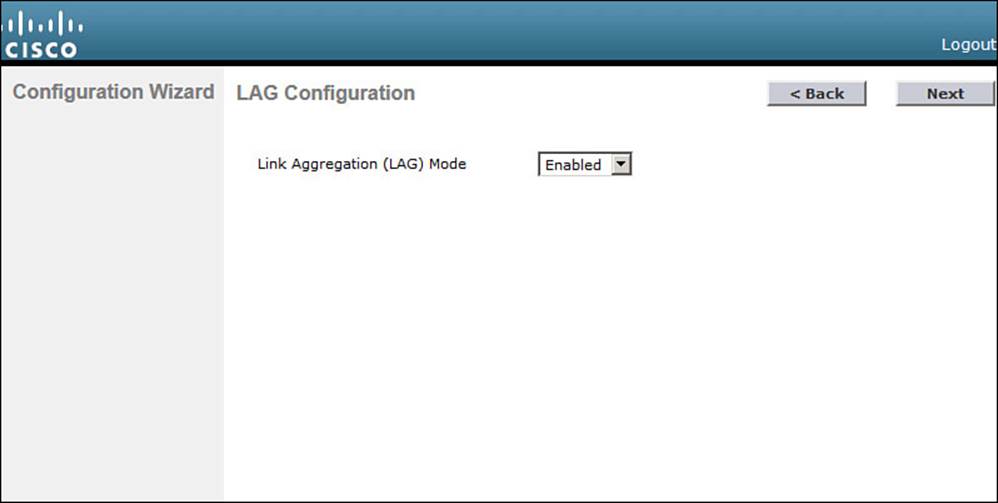
Figure 10-6 Configuring LAG Mode
Step 5. Configure the management interface.
By default, a controller can use a single management interface for both management and CAPWAP traffic, if no AP-manager interface is configured. The management interface is configured for VLAN 0 (the 802.1Q trunk native VLAN), with no valid IP address. You can set the VLAN number, IP address, subnet mask, and gateway as shown in Figure 10-7. In this example, the management interface resides on VLAN 50 at 192.168.50.10. You can also configure the primary and secondary DHCP server addresses that the controller will use if it has to relay any DHCP requests from wireless clients. Click Next to continue.
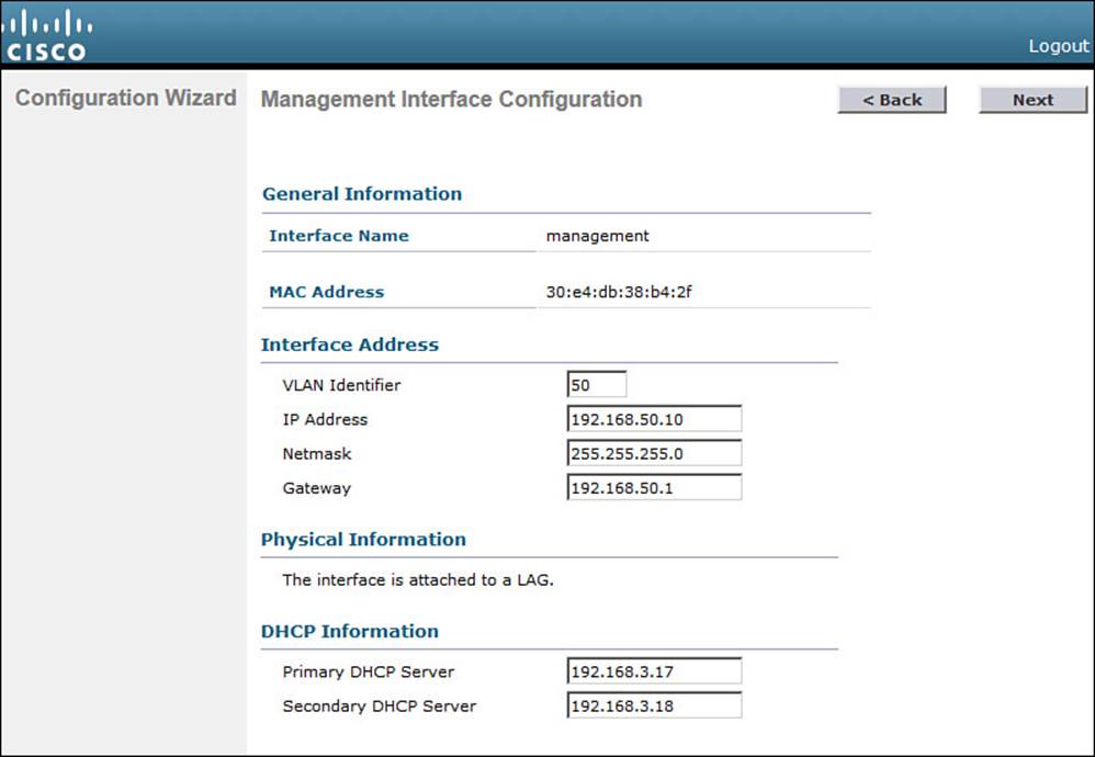
Figure 10-7 Configuring the Management Interface
Tip
You might have noticed that the controller’s native VLAN is VLAN 0, whereas Cisco switches use native VLAN 1 as a default. A controller and a switch may communicate over the native VLAN because traffic is untagged. Even though the native VLAN numbers differ, it does not matter because no tag is added at all.
Step 6. Configure the RF mobility domain and country code.
A controller must be configured to use the RF parameters that are defined by the local regulatory body. It also uses an RF mobility domain name to group like controllers together so that things such as AP channel numbers and transmit power can be centrally managed. By default, the RF mobility domain is set to default. You can override that value as shown in Figure 10-8. Although the selected country code is not shown in the figure, it has defaulted to US. Click Next to continue.
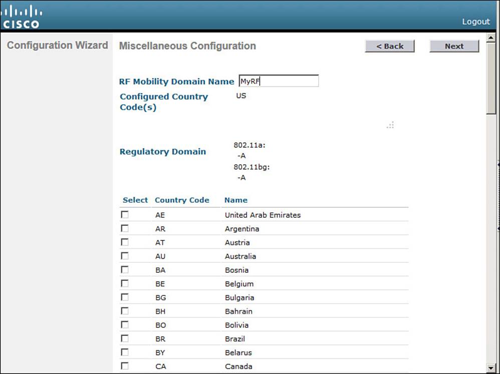
Figure 10-8 Configuring the RF Regulatory Domain
Step 7. Configure the virtual interface.
Enter an IP address for the virtual interface, such as the one shown in Figure 10-9. You should have an entry for the virtual interface in your DNS server, to streamline client web authentication. You can also configure a DNS hostname on the controller, but that same name should also exist on the DNS server. Click Next to continue.
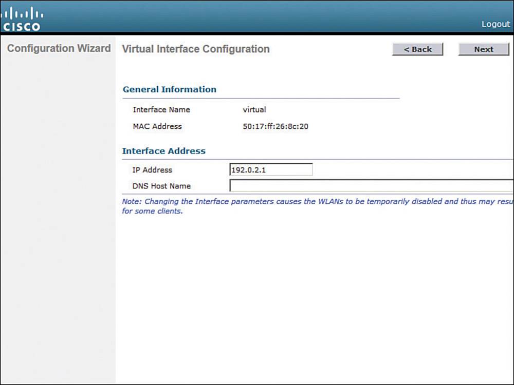
Figure 10-9 Configuring the Virtual Interface
Step 8. Configure a WLAN.
During the initial setup, you must define one wireless LAN, as shown in Figure 10-10. The profile name is the name of the WLAN within the controller. The WLAN SSID is the SSID string that will be advertised by any APs that offer the WLAN. You might find it convenient to configure both strings with the same name, as shown in the figure.
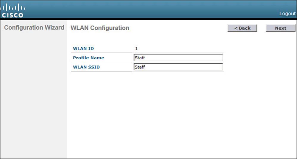
Figure 10-10 Configuring a WLAN
Notice that you only need to enter the name of the WLAN—not a VLAN number or an interface name. The initial setup process creates a placeholder for the WLAN. You will complete the WLAN configuration later, when the controller reboots and becomes fully functional.
After you click Next to continue, you will see a reminder window noting that the WLAN has been created with the following default wireless security settings: WPA2, AES, and 802.1x authentication. Chapter 14, “Wireless Security Fundamentals,” covers these terms in greater detail.
Tip
The WLAN Configuration screen also shows a WLAN ID number. As you create new WLANs, the ID number increments. The WLAN ID is an internal index that is used to call the WLAN from other menus, as well as when configuration templates are applied to a controller from a Cisco Prime Infrastructure (PI) management station.
Step 9. Configure a RADIUS server.
As an optional step, you can define a RADIUS server that will be used for client authentication. You can always click the Skip button to skip this step and define the server at a later time.
If you choose to define the server now, enter the RADIUS server’s IP address, shared secret key, port number, and the server status. Figure 10-11 shows these fields. You use the Server Status field when multiple servers are defined; the controller will send a request to the next server that is in the Enabled state in the list. Click Apply to apply the settings and continue to the next step.
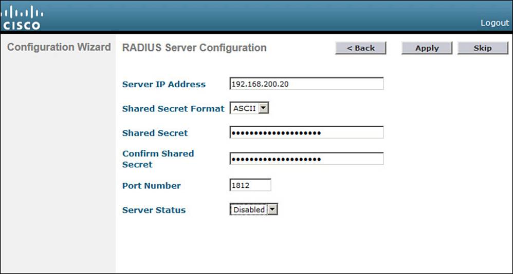
Figure 10-11 Configuring a RADIUS Server
Step 10. Configure 802.11 support.
By default, a controller enables 802.11a, 802.11b, and 802.11g support globally for all APs that associate with it. You can override the support settings by changing the check boxes shown in Figure 10-12. When the initial setup is complete and the controller has rebooted into full functionality, you can fine-tune the 802.11 support settings further.

Figure 10-12 Configuring 802.11 Support
Also by default, the controller enables Auto-RF, which will automatically determine the channel and transmit power level for each AP’s radio. You can always fine-tune the Auto-RF settings globally or on a per-AP basis at a later time. Click Next to continue.
The Auto-RF functions are also known as Radio Resource Management (RRM), which is covered in greater detail in Chapter 13, “Understanding RRM.”
Step 11. Configure the system clock.
The controller maintains an internal clock. You can set the date, time, and time zone, as shown in Figure 10-13. Click Next to continue. After the controller has rebooted and is fully functional, you can configure it to use an NTP server to synchronize its clock.
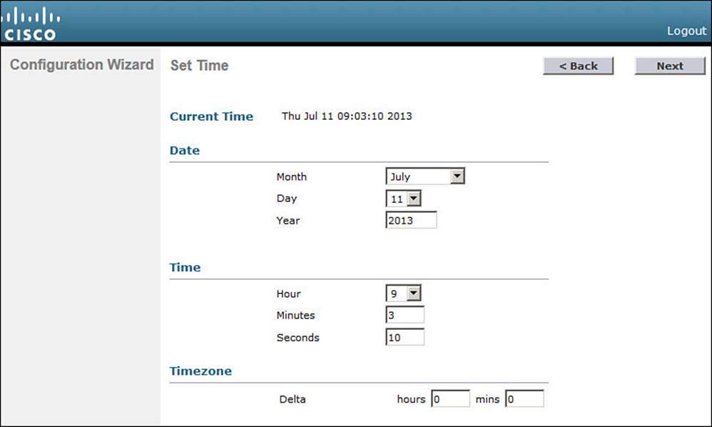
Figure 10-13 Configuring the System Clock
Step 12. Reboot the controller.
As a last step, to save the initial configuration and reboot the controller, click the Save and Reboot button (see Figure 10-14).
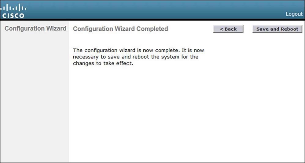
Figure 10-14 Save and Reboot After Completing the Configuration Wizard
After the controller has rebooted, it will be fully functional. At that time, you can reposition your PC on the regular wired network and point your web browser toward the controller’s management interface IP address. You will have to log in using the administrative user ID and password that you configured in Step 1.
Initial Setup of a Converged Controller with the Configuration Wizard
The initial configuration procedure for a converged Wireless Controller Module (WCM) is very similar to that of a centralized controller. One important difference is that the converged controller shares the same hardware platform and management interface with the access layer switch. That means you must configure all of the WCM features through the switch console port, a Telnet/SSH session, or a web-based GUI, as if you were configuring the switch itself.
To access the Configuration Wizard web page, you must first configure remote web access on the switch and enable the integrated web server. In Example 10-1, VLAN 2 has been created for switch management traffic, including WLC management. The management interface SVI sits on VLAN 2 with IP address 192.168.1.10. Web-based management requires user authentication, so a local username “admin” has been created with privilege level 15 so that configuration changes can be made. Local user authentication is configured for the HTTP server. To increase security, the regular HTTP server is disabled and the HTTPS secure server is enabled.
Example 10-1 Initial Switch Configuration for Web-based Management
Switch(config)# vlan 2
Switch(config-vlan)# name Switch Management
Switch(config-vlan)# exit
Switch(config)# interface vlan 2
Switch(config-if)# description Management Interface
Switch(config-if)# ip address 192.168.1.10 255.255.255.0
Switch(config-if)# no shutdown
Switch(config-if)# exit
!
Switch(config)# username admin privilege 15 password secretpassword
Switch(config)# ip http authentication local
Switch(config)# no ip http server
Switch(config)# ip http secure-server
Next, from your PC, make sure you can reach the management interface address that you just configured. For example, try to ping 192.168.1.10. If the switch is not reachable, verify that you are connected to a switch interface that is assigned to or that can reach the management VLAN. Once you can reach the switch, open a web browser to the switch management address and log in with your credentials. Following Example 10-1, you would open the browser to https://192.168.1.10 to access the switch, as shown in Figure 10-15.
![]()
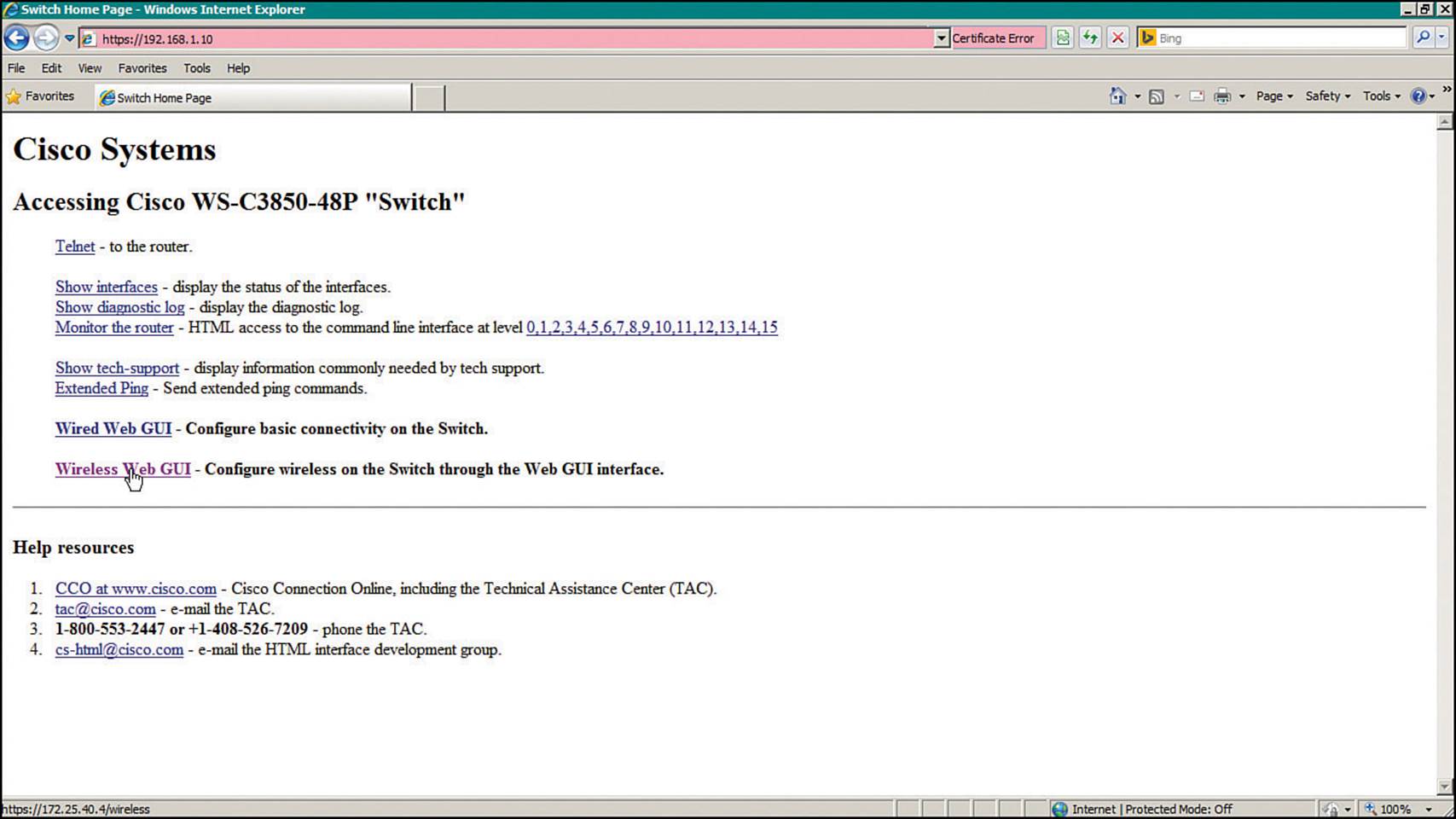
Figure 10-15 Accessing the Switch Management Web Page
Click the Wireless Web GUI link to access the WLC management page that is displayed in Figure 10-16. From this page, you can monitor, configure, and administer the converged WLC on the switch. For the initial configuration, select Configuration > Wizard.
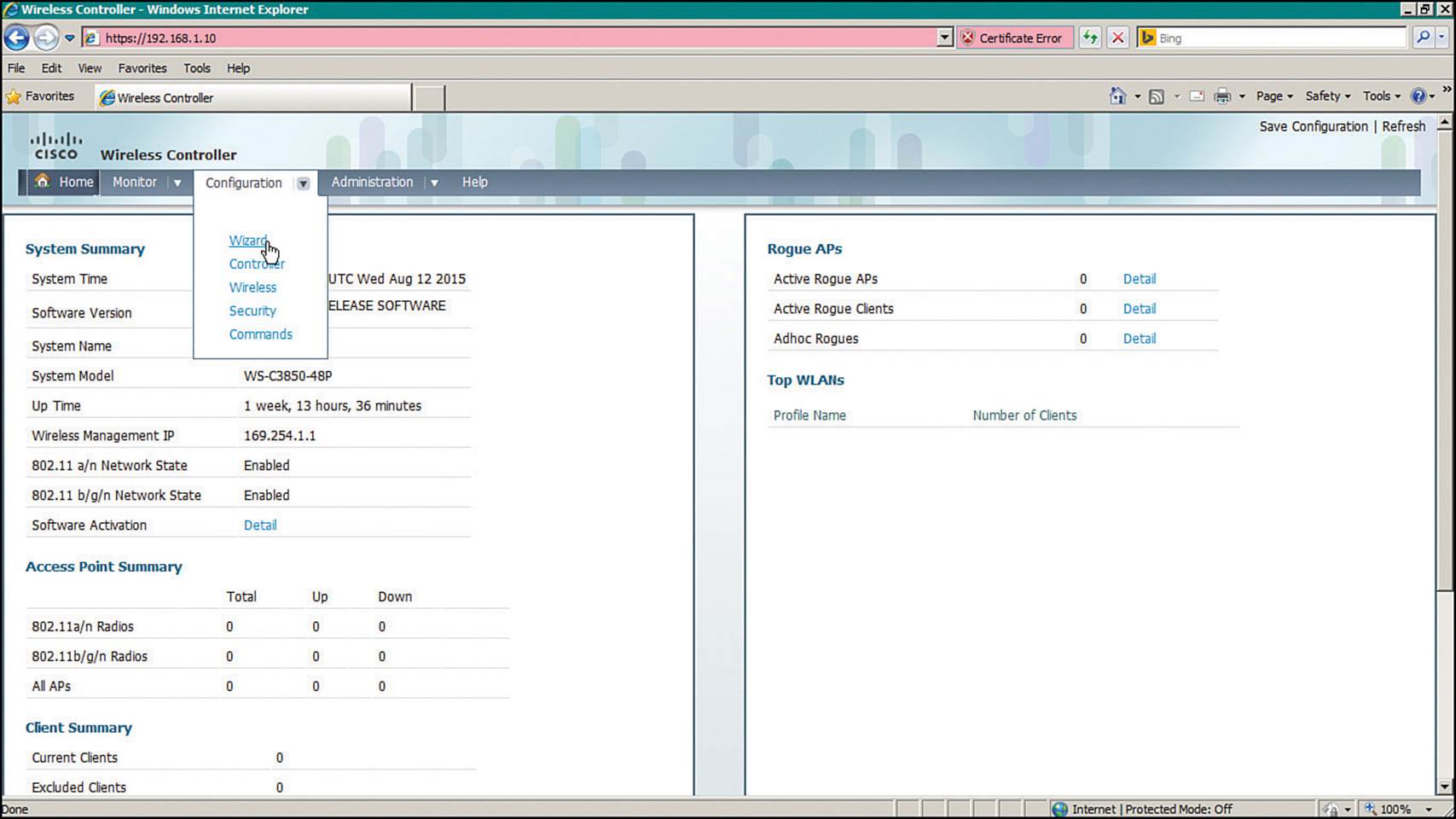
Figure 10-16 Initiating the WLC Configuration Wizard
The Configuration Wizard breaks the initial configuration into the following nine steps:
Step 1.Admin Users—Configure one username and password for WLC management, as shown in Figure 10-17.
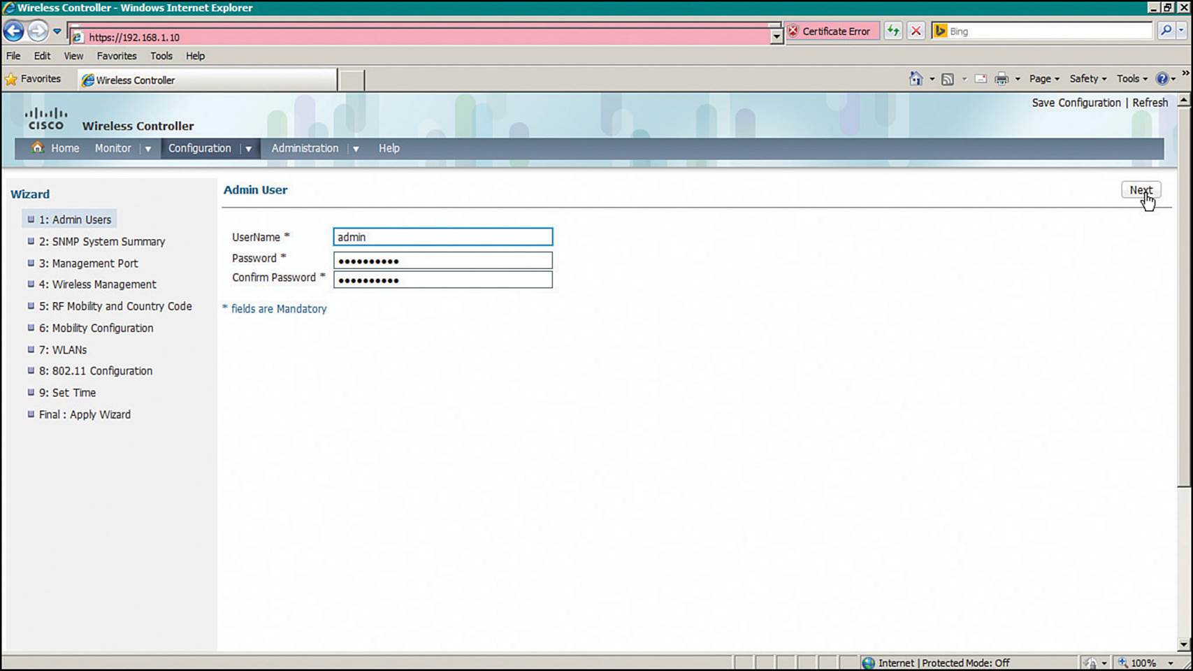
Figure 10-17 Creating an Administrative User for Converged WLC Management
Step 2.SNMP System Summary—Set basic SNMP parameters as shown in Figure 10-18.
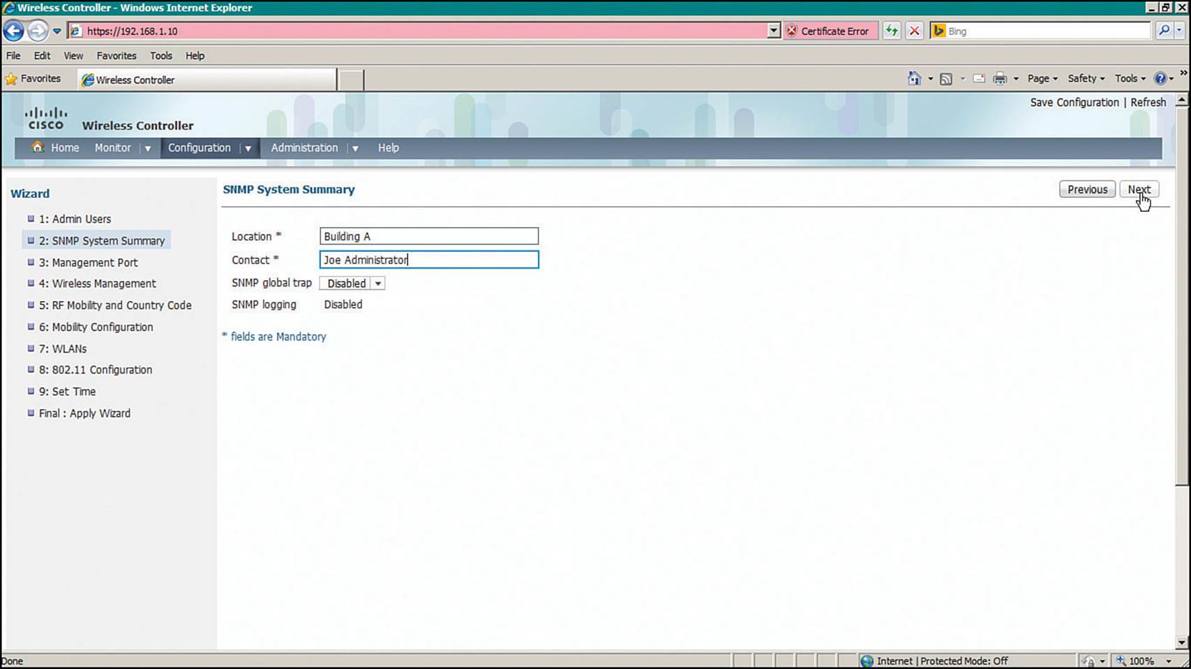
Figure 10-18 Setting Basic SNMP Parameters on a Converged WLC
Step 3.Management Port—Identify the interface to be used as the WLC service port, along with IP addressing information, as shown in Figure 10-19.
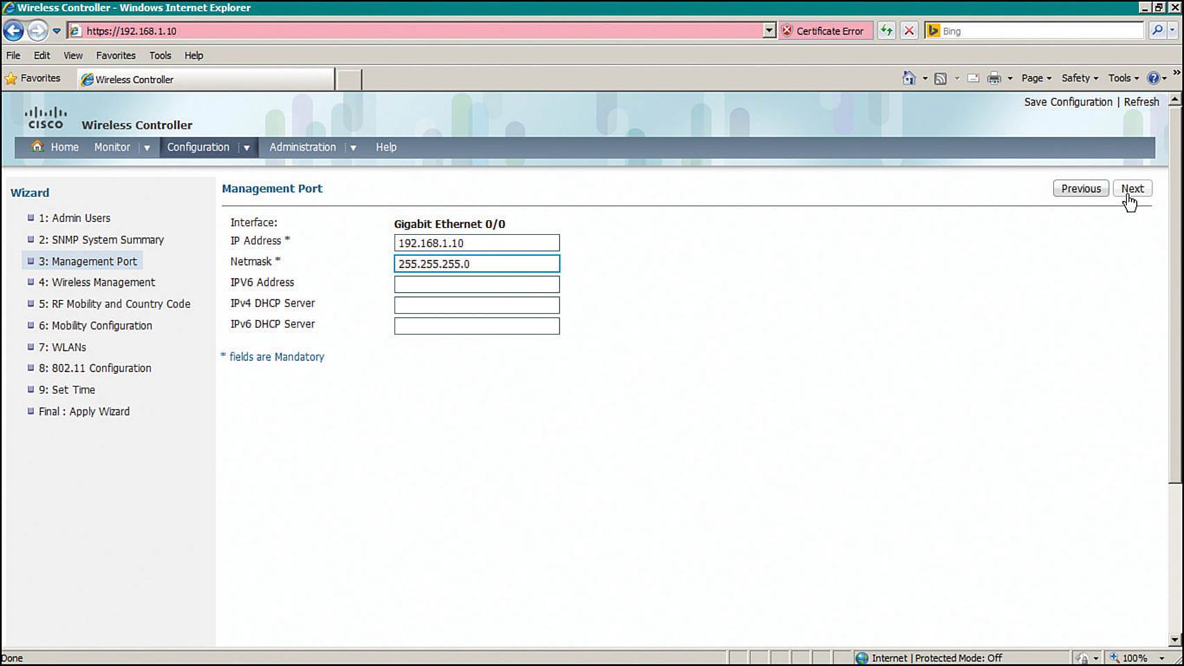
Figure 10-19 Configuring a Converged WLC Management Port
Step 4.Wireless Management—Configure the management and dynamic interfaces, along with their VLAN numbers and IP addresses, as shown in Figure 10-20.
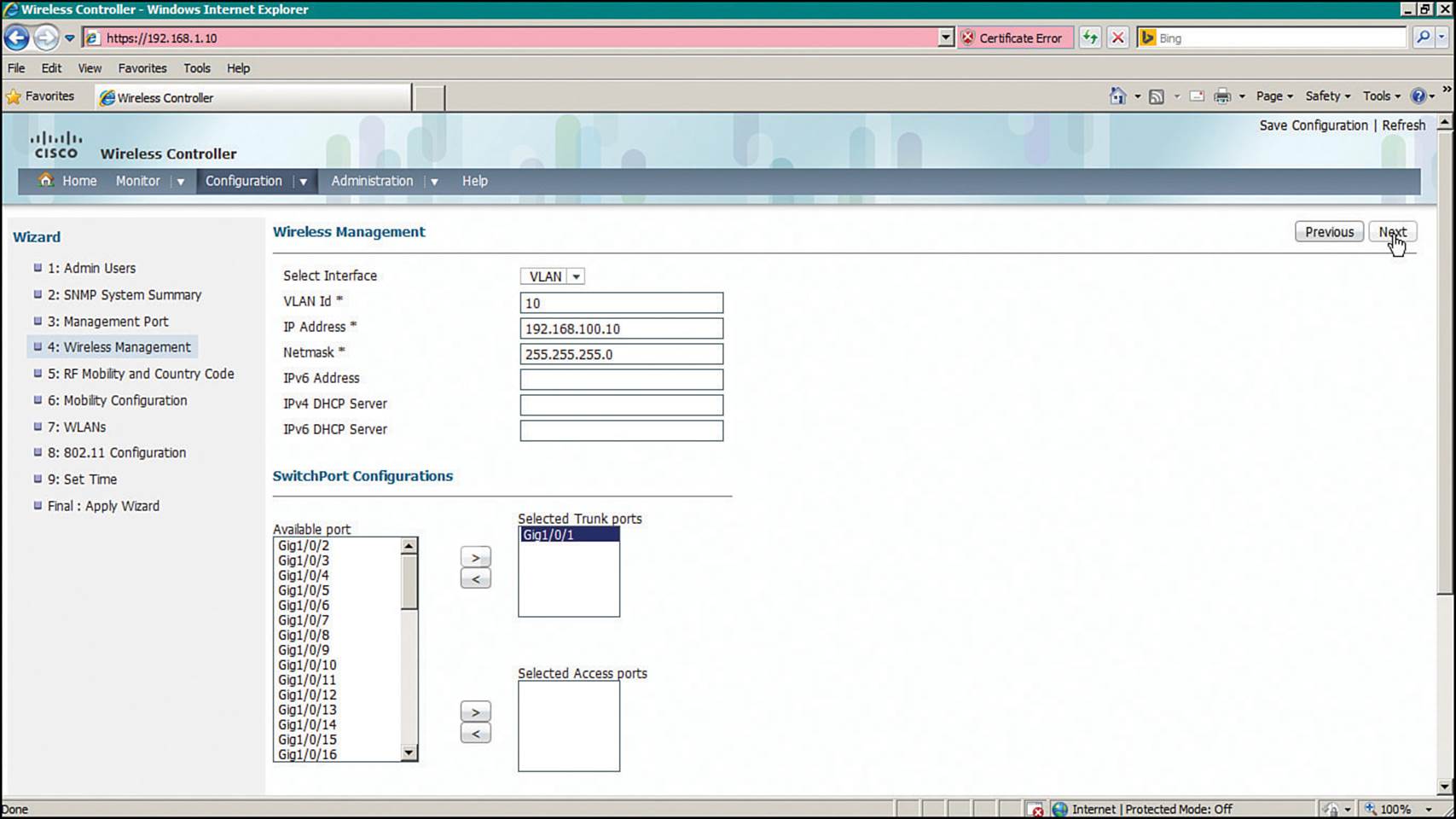
Figure 10-20 Configuring Converged WLC Wireless Management
Step 5.RF Mobility and Country Code—Define the RF mobility group name and country code as shown in Figure 10-21.
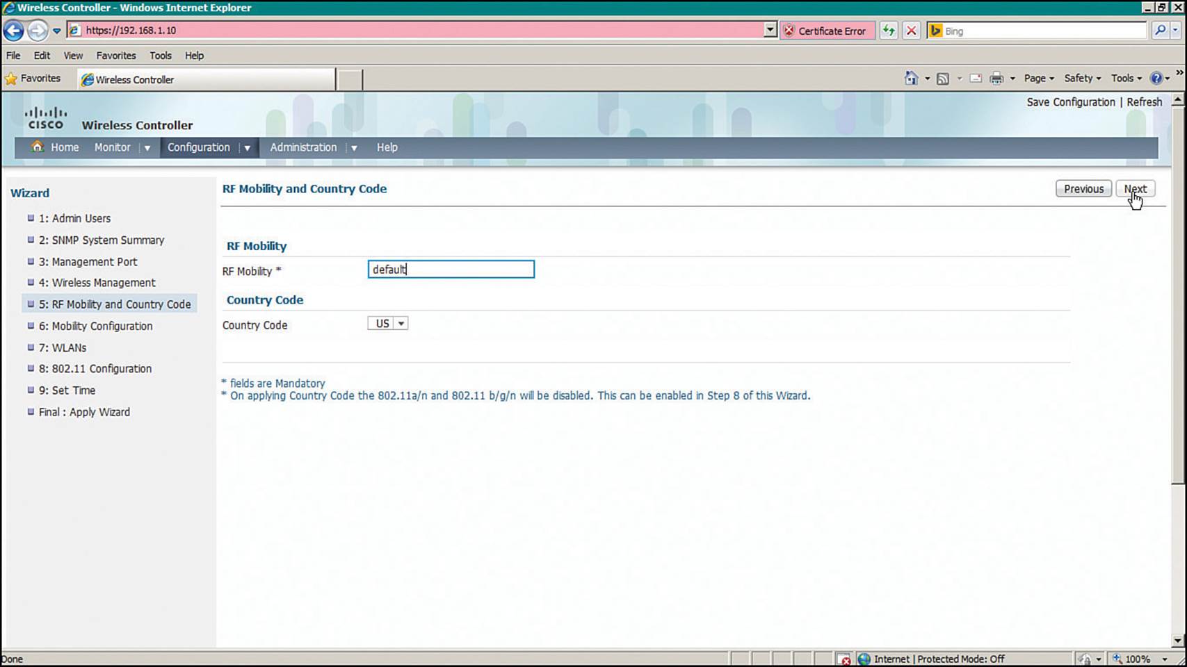
Figure 10-21 Configuring Converged WLC RF Mobility
Step 6.Mobility Configuration—Set the mobility parameters that will be used to manage roaming clients, as shown in Figure 10-22.
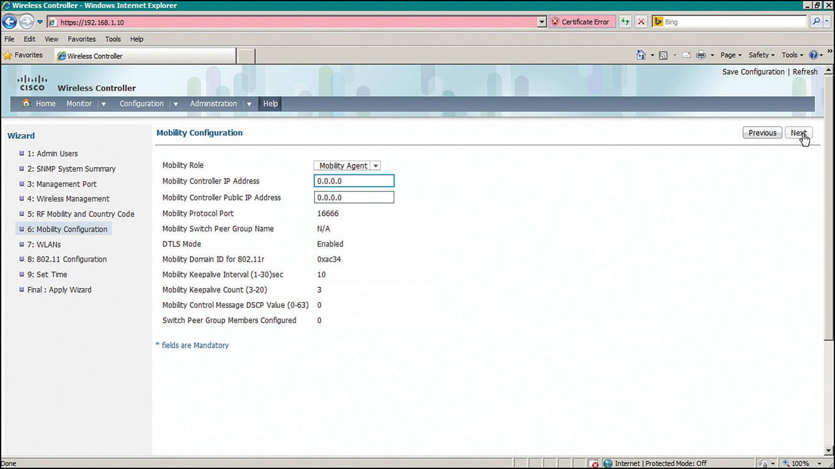
Figure 10-22 Configuring Converged WLC Mobility
Step 7.WLANs—Map an SSID to a VLAN using the fields shown in Figure 10-23.
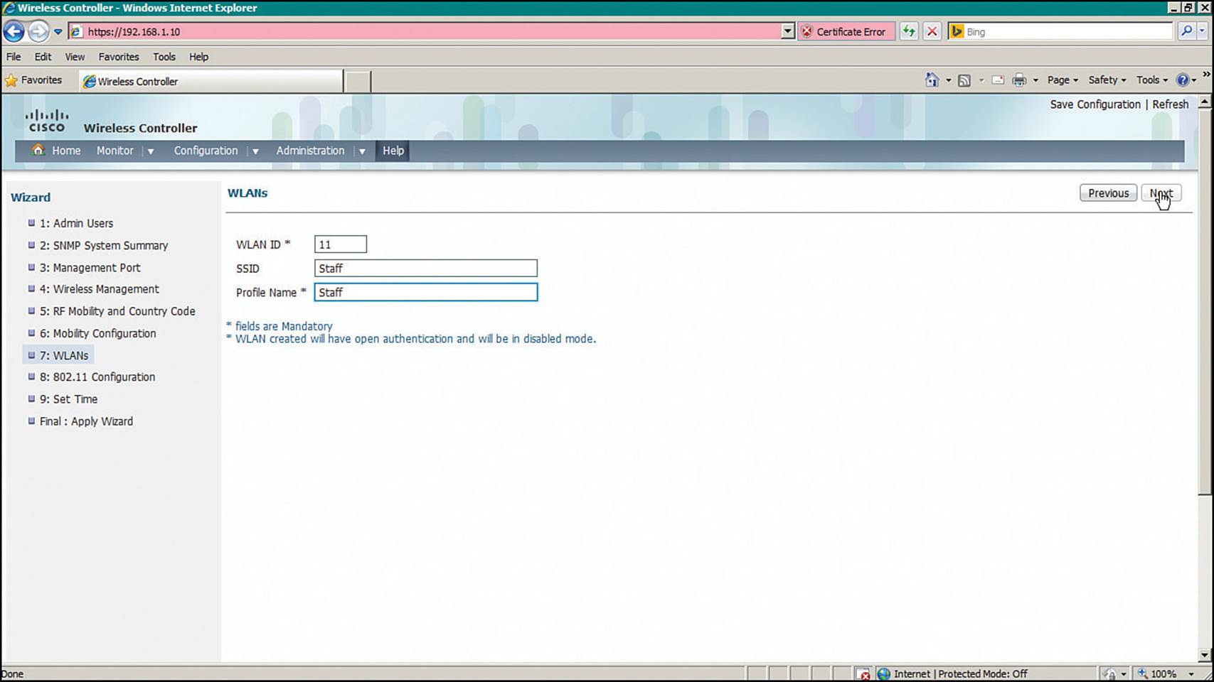
Figure 10-23 Configuring a WLAN on a Converged WLC
Step 8.802.11 Configuration—Enable the 2.4- and 5-GHz bands as shown in Figure 10-24.
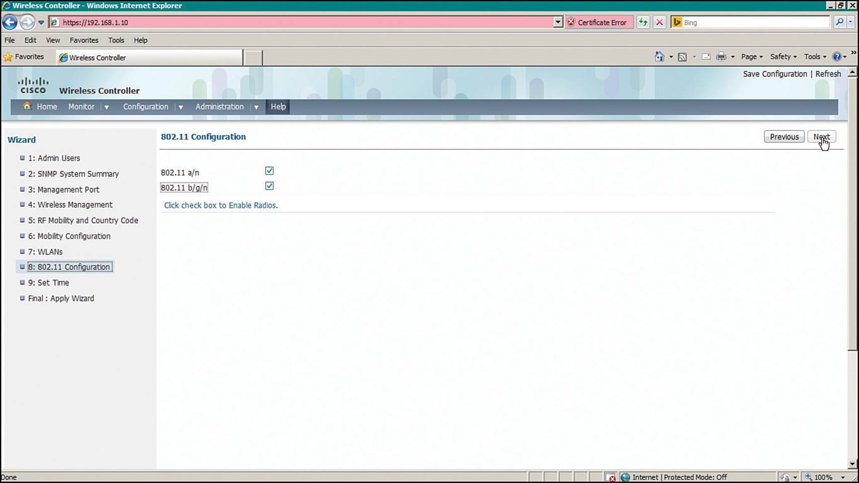
Figure 10-24 Enabling 802.11 on a Converged WLC
Step 9.Set Time—Set the WLC clock and calendar using the fields shown in Figure 10-25.
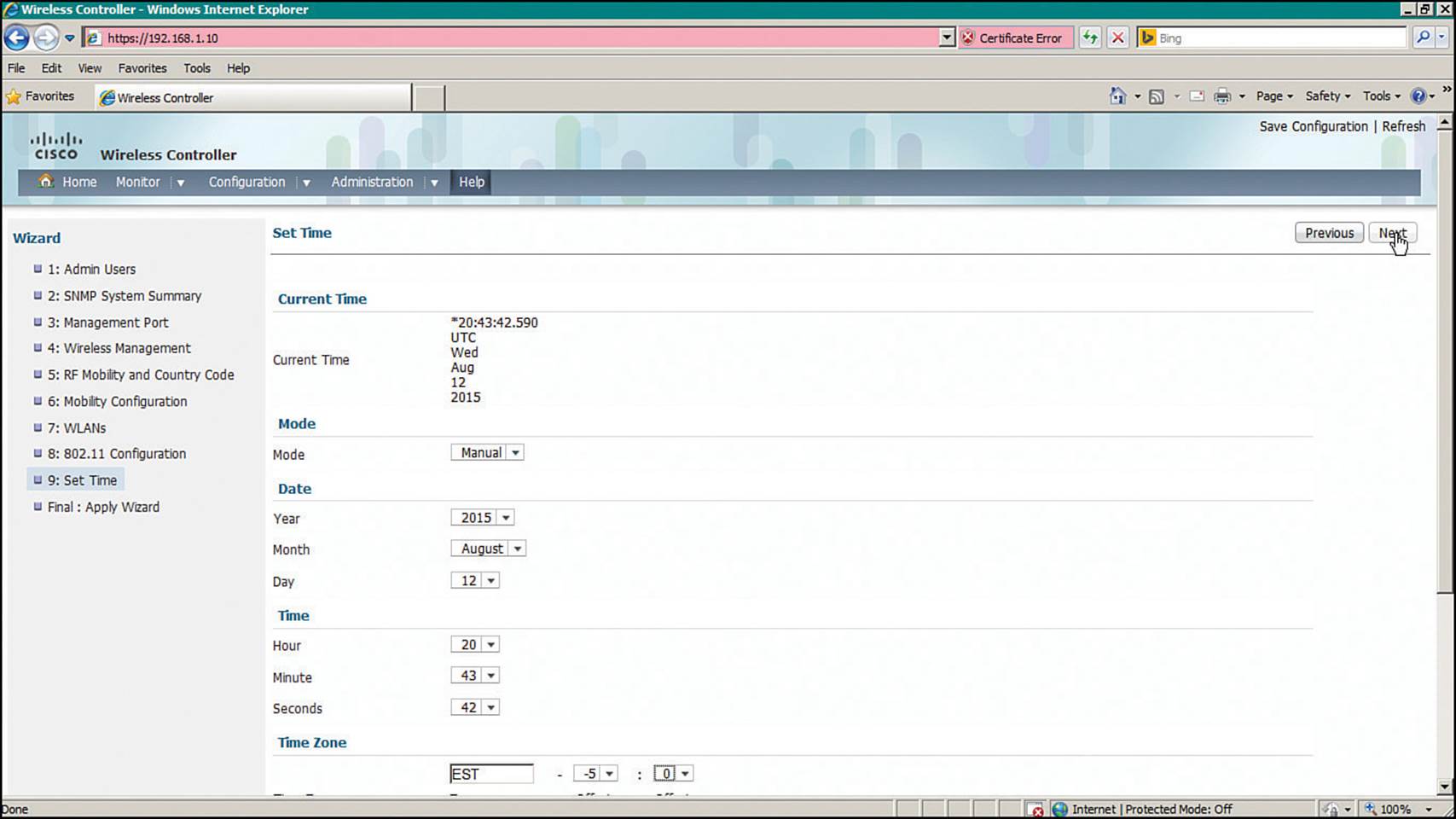
Figure 10-25 Setting the Clock on a Converged WLC
At this point, you can view the entire initial configuration on one web page, as shown in Figure 10-26, step Final: Apply Wizard. If everything is correct, click the Apply button in the upper-right corner of the page.
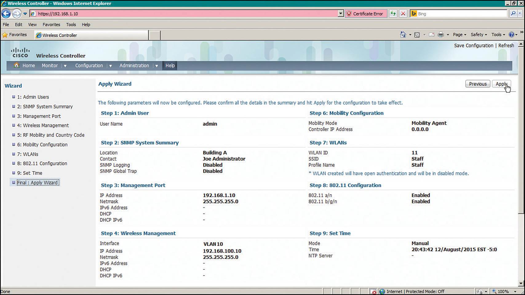
Figure 10-26 Verifying the Initial Converged WLC Configuration
The parameters in the converged and centralized WLC configuration wizards are very similar, with one exception. Converged mobility involves a specific role assignment for the access layer switch. The mobility roles and hierarchy are discussed in greater detail in Chapter 12, “Understanding Roaming.”
Initial Setup of a Centralized Controller with WLAN Express Setup
Beginning with AireOS 8.1, Cisco WLCs offer an alternate method called WLAN Express Setup (WES) for entering the initial configuration. On the 2504 WLC, WES is available beginning with AireOS 8.0. Through WES, you can prepare a controller by entering parameters into a few web pages. WES differs from the traditional web-based Configuration Wizard by making the initial configuration process more efficient and effective. For example, you can complete the WES process after only two web pages, and WES automatically applies parameters that are considered best practices for you. You can use the following steps to complete WES.
Step 1. Enter an administrative username and password.
Connect your PC to the same VLAN and subnet that the controller’s service port uses and then open a web browser to the controller’s default IP address 192.168.1.1. On a 2504, you can connect directly to one of the four Ethernet ports instead. Enter a username and password that you will use to configure and maintain the controller in the future, as shown in Figure 10-27. Click the Start button to begin the initial configuration.
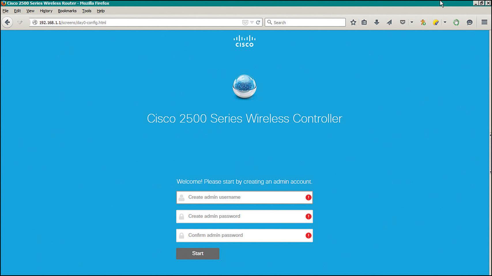
Figure 10-27 Beginning the WLAN Express Setup
Step 2. Identify the controller.
Next, enter a name for the controller as shown in Figure 10-28. Set the time parameters by selecting the country and timezone, then set the date and time and identify an NTP server. Enter the IP address, subnet mask, and default gateway that the controller will use for management purposes. Select the VLAN number that will be used for management traffic. By default, VLAN 0 is used to signify that management traffic is untagged on the native VLAN of a trunk link. Click the Next button to continue.
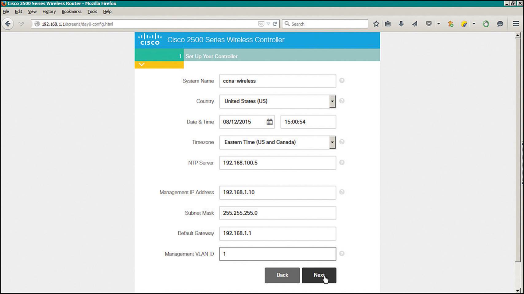
Figure 10-28 Entering Management Parameters
Step 3. Configure initial wireless networks.
You can configure up to two WLANs during the express setup: an “Employee” network and a “Guest” network. To enable the WLAN, click the check mark button; to disable the WLAN, click the × button. In Figure 10-29, an Employee network named “staff” is enabled and configured, while the Guest network is disabled. Then for each WLAN that is enabled, enter the network name (SSID), a wireless security method and parameters, and the VLAN number that will be mapped to the WLAN. By default, the management VLAN is selected. You can create a new VLAN by selecting New VLAN from the VLAN drop-down menu.
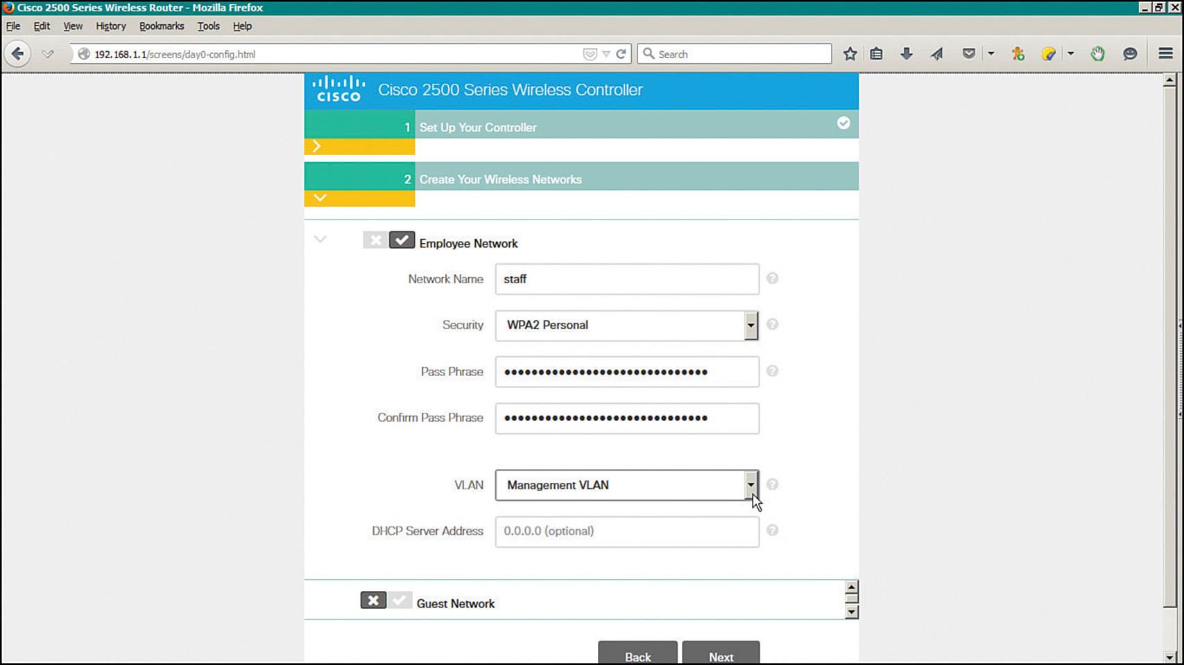
Figure 10-29 Configuring Initial Wireless Networks
Enter the IP address that the controller will use on the dynamic interface that is mapped to the VLAN, along with the subnet mask, default gateway address, and an optional DHCP server address. Figure 10-30 shows the same web page shown in Figure 10-29, scrolled down to reveal the VLAN and IP addressing parameters.
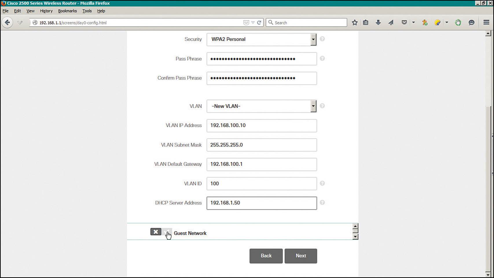
Figure 10-30 Entering VLAN and IP Address Parameters for a Wireless Network
Click the Next button to continue.
Step 4. Verify the initial configuration.
Next, review the parameters you have entered, as shown in Figure 10-31. Click the Back button to return to previous pages to make corrections or click the Apply button to apply the initial configuration. Once applied, the controller will save its configuration and will reboot. From this point, you can open your web browser to the controller’s management IP address and continue with further configuration tasks.
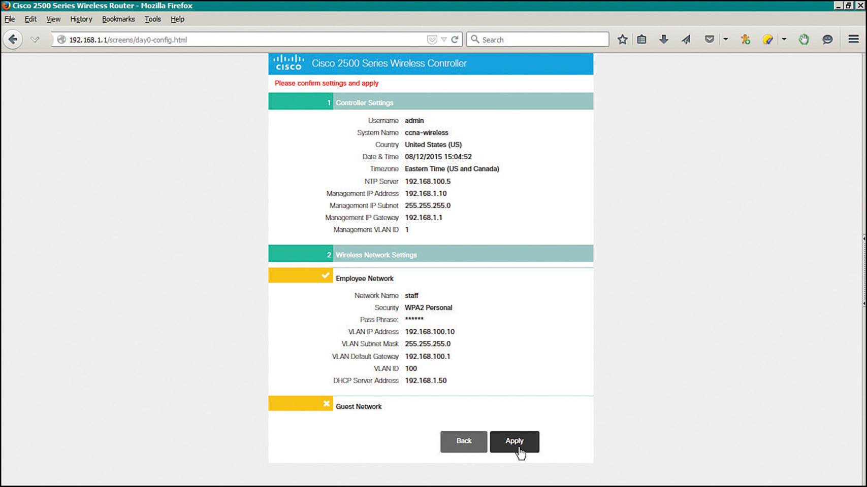
Figure 10-31 Verifying the Initial Configuration
Initial Setup of a Centralized Controller with the CLI
As an alternative to using a web browser for the initial setup, you can connect your PC to the controller’s asynchronous console port and use the CLI. Your terminal emulator will need to be configured for 9600 baud, 8 data bits, and 1 stop bit—the same settings you use to access the console ports on most Cisco routers and switches.
For comparison, the same parameters used in the web-based initial setup are used to demonstrate the CLI initial setup in Example 10-2. Notice that some CLI prompts end with things like [yes][NO]. You can enter either string option shown (yes or NO) or you can press Enter to use the capitalized default value.
Example 10-2 Using the Controller CLI for Initial Setup
Welcome to the Cisco Wizard Configuration Tool
Use the '-' character to backup
Would you like to terminate autoinstall? [yes]:
AUTO-INSTALL: starting now...
System Name [Cisco_38:b4:2f] (31 characters max): WLC-1
Enter Administrative User Name (24 characters max): admin
Enter Administrative Password (3 to 24 characters): **********
Re-enter Administrative Password : **********
Service Interface IP Address Configuration [static][DHCP]: DHCP
Management Interface IP Address: 192.168.50.10
Management Interface Netmask: 255.255.255.0
Management Interface Default Router: 192.168.50.1
Management Interface VLAN Identifier (0 = untagged): 50
Management Interface DHCP Server IP Address: 192.168.3.17
Virtual Gateway IP Address: 10.1.1.1
Mobility/RF Group Name: MyRF
Network Name (SSID): Staff
Configure DHCP Bridging Mode [yes][NO]:
Allow Static IP Addresses [YES][no]:
Configure a RADIUS Server now? [YES][no]:
Enter the RADIUS Server's Address: 192.168.200.20
Enter the RADIUS Server's Port [1812]:
Enter the RADIUS Server's Secret: thisismysharedsecret
Enter Country Code list (enter 'help' for a list of countries) [US]:
Enable 802.11b Network [YES][no]:
Enable 802.11a Network [YES][no]:
Enable 802.11g Network [YES][no]:
Enable Auto-RF [YES][no]:
Configure a NTP server now? [YES][no]:
Enter the NTP server's IP address: 192.168.200.30
Enter a polling interval between 3600 and 604800 secs: 3600
Configuration correct? If yes, system will save it and reset. [yes][NO]: yes
Maintaining a Wireless Controller
Like Cisco routers, switches, and other networking devices, wireless controllers maintain configuration files and run operating system images. As a CCNA Wireless engineer, you will likely be involved in maintaining controllers on a network and dealing with the information and files they use. The following sections explain how you can interface with controllers and APs so that you can upload and download their files.
Backing Up Controller Configurations
As you make configuration changes to a wireless controller, you must click the Apply button to make the changes active. This is similar to configuring a router or switch, where changes take effect immediately and are updated in the running configuration but are not saved to the startup configuration. As long as the controller stays up, your changes will stay active. If the controller reboots or loses power, your changes will be lost.
A controller also has nonvolatile storage for its configuration, much like flash memory. You can save the configuration by selecting the Save Configuration link at the upper right of any controller web page.
It is important to save the controller configuration to flash memory so that any configuration changes are retained. Beyond that, you should think about saving the configuration to a location away from the controller itself. If the controller hardware ever fails and you receive a replacement, you will need a way to access the configuration so you can import it into the new unit.
From the controller GUI, navigate to Commands > Upload File; on a WCM, navigate to Configuration > Commands > Upload File. Select Configuration from the file type drop-down menu. Select either TFTP or FTP and enter the IP address, file path, and target filename, as shown inFigure 10-32. The controller configuration will be transferred and saved in cleartext, showing the CLI commands that are used to build the entire configuration. Select the Configuration File Encryption checkbox and enter an encryption key string to encrypt the configuration file so that it cannot be read easily. The file contents will be decrypted when they are transferred back onto a WLC.
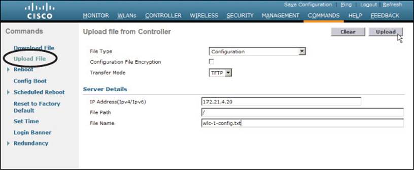
Figure 10-32 Saving a Wireless Controller Configuration
When you have an offline copy of the configuration file, you can download the contents to a controller to restore the configuration or to overwrite the configuration that is already in use. This process is just the opposite of uploading the configuration to your PC: Select Commands > Download File, select file type Configuration, and enter the TFTP or FTP server parameters and filename.
Tip
On a WCM, the configuration is contained in the running configuration of the switch platform.
Updating Wireless LAN Controller Code
Like any other network device, a controller requires a code image to operate. Periodically, you might want to upgrade the code image to a new release so that you can take advantage of bug fixes and new features. Less often, you might have to downgrade the code image to return to a more stable version.
A WLC maintains two separate code images: a primary image and a backup image. When a controller boots up, it runs the primary image by default. That means you can download a new image file into the backup position on the controller while it is running, with no interruption of service. To run the new image, you must reboot the controller. You can display the two code image versions by navigating to Commands > Config Boot, as shown in Figure 10-33. You can select the image that will be run after the next reboot with the Config Boot Image drop-down menu.
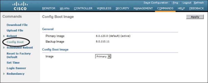
Figure 10-33 Displaying Controller Code Images
To download a new code image, go to Commands > Download File. The controller can download from a TFTP or an FTP server. Select Code as the file type, then enter the file server’s IP address, file path, and code image filename. For an FTP download, enter the credentials required by the FTP server. Next, click the Download button to start the file transfer.
Tip
The file transfer terminology might be a bit different than you are used to seeing. The terms “download” and “upload” refer to the controller’s perspective, as if it acts like a client. You always download to the controller and upload from it.
WLC image files are usually named according to the hardware platform and the release number and end with a .aes suffix, as in AIR-WISM2-K9-7-2-115-2.aes. During the download, the WLC will periodically update the web page to display the following sequence of status messages (this process can take several minutes):
1. TFTP Code transfer starting.
2. TFTP receive complete...extracting components.
3. Executing backup script.
4. Writing new RTOS to flash disk.
5. Writing new FP to flash disk.
6. Writing new APIB to flash disk.
7. Executing install_apib script.
8. Executing fini script.
9. TFTP File transfer is successful.
At this point, the new image is ready to be used. You must reboot the controller to run the new image, according to the status message shown in Figure 10-34. Be aware that rebooting the controller will interrupt wireless service. All of the APs joined to the controller will lose contact with it and will rehome to a secondary controller (if one is configured) or begin the controller discovery process to find a new home.
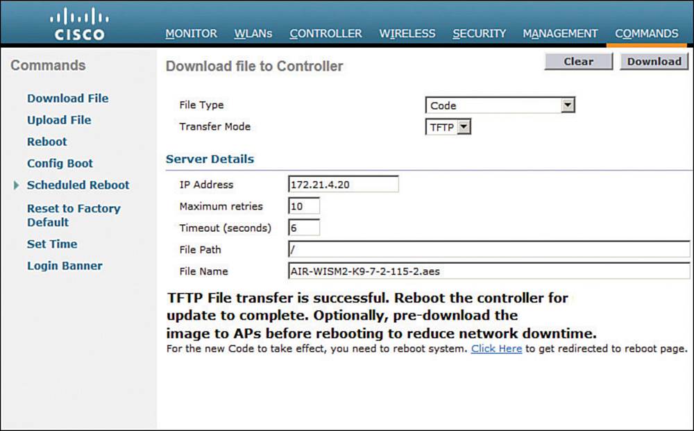
Figure 10-34 After an Image Download, the WLC is Ready to Reboot
You can get ready to reboot the controller by selecting the Click Here link at the bottom of the download status or by navigating to Commands > Reboot, as shown in Figure 10-35. You can save the current controller configuration and reboot immediately by clicking the Save and Rebootbutton.
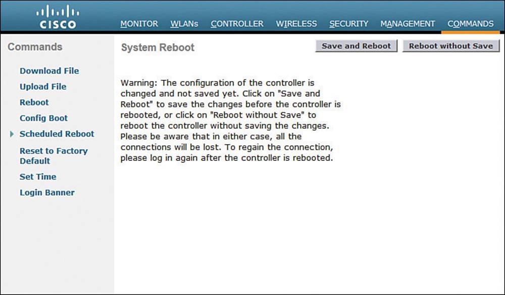
Figure 10-35 Triggering a WLC Reboot
After you install a new controller image file, should you install the same code release on the lightweight APs? Recall that the controller manages all aspects of the APs, including their code images. When a lightweight AP joins a controller, it compares its own code release with that of the controller. If the images differ, the AP will download a matching image from the controller automatically. Therefore, after the controller reboots and begins to run a new image, each AP will download the same release as it rejoins the controller.
As you might imagine, the code upgrade process can impose an extensive outage on a wireless network. The controller must be rebooted so that it can begin running the new image. After that, each AP must go offline to download the new image, reboot, and begin running the new image. To lessen the impact to wireless users, controller releases 7.2 and later can “pre-download” or push a new code image to the APs before the controller or the APs need to reboot. This prepares the APs ahead of time so that they can reboot in parallel with the controller and begin running the new code image much sooner.
Updating Wireless Control Module Code
A converged wireless network uses Wireless Control Modules (WCMs) rather than WLCs. The functionality is the same from a wireless perspective but differs in the way code images are managed. A WCM is actually a module embedded in a Cisco Catalyst access switch, so the two functions must share the same hardware platform. In addition, the two functions share a common software platform called IOS-XE that provides the traditional Cisco IOS Software for the switch. IOS-XE can also host other software applications, such as WCM and Wireshark.
IOS-XE is actually a bundle of multiple software package files that include things like a base kernel, platform drivers, infrastructure management, a Cisco IOS image, platform-specific functions, and WCM. Devices running IOS-XE can boot in one of two modes: Install Mode or Bundle Mode. The WLC 5760 is an exception because it supports only the Install mode.
Install Mode expands the bundled packages, copies them to flash memory, then boots and runs the appropriate software. Bundle Mode does not expand the packages but boots from the bundle directly. Because Bundle Mode must deal with the bundled packages during boot time, it requires more system resources and sometimes restricts available features. Therefore, Cisco recommends using the default Install Mode instead.
To upgrade the code running on a WCM, you must upgrade the code running on the switch platform. Catalyst 3850 and 3650 switches can be configured as logical switch stacks. A single stack can consist of up to nine individual switches that are connected through their StackWise-480 ports. One switch operates as a master switch, controlling the stack as a whole, while another operates as a standby switch that is ready to take over if the master fails. The master switch maintains the running and startup configurations for all members of the stack.
Also, each switch in the stack should run the same IOS-XE software version. You can upgrade the code image by installing an IOS-XE image bundle with the following command:
Switch# software install file source:filename.binnew
Over time, you might end up with several software bundles stored on the switch flash filesystem but are no longer used. You can safely remove redundant or extraneous packages with the following command:
Switch# software clean file flash: switch switch#
Exam Preparation Tasks
As mentioned in the section, “How to Use This Book,” in the Introduction, you have a couple of choices for exam preparation: the exercises here, Chapter 21, “Final Review,” and the exam simulation questions on the DVD.
Review All Key Topics
Review the most important topics in this chapter, noted with the Key Topic icon in the outer margin of the page. Table 10-3 lists a reference of these key topics and the page numbers on which each is found.
![]()
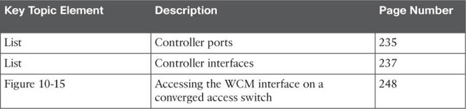
Table 10-3 Key Topics for Chapter 10
Define Key Terms
Define the following key terms from this chapter and check your answers in the glossary:
controller interface
controller port
distribution system port
dynamic interface
link aggregation group (LAG)
management interface
service port
virtual interface
All materials on the site are licensed Creative Commons Attribution-Sharealike 3.0 Unported CC BY-SA 3.0 & GNU Free Documentation License (GFDL)
If you are the copyright holder of any material contained on our site and intend to remove it, please contact our site administrator for approval.
© 2016-2026 All site design rights belong to S.Y.A.