CCNA Wireless 200-355 Official Cert Guide (2016)
Chapter 9. Implementing Autonomous and Cloud Deployments
This chapter covers the following topics:
![]() Initially Configuring an Autonomous AP—This section explains how to connect and configure an access point to form a functional basic service set and how to upgrade the AP’s software.
Initially Configuring an Autonomous AP—This section explains how to connect and configure an access point to form a functional basic service set and how to upgrade the AP’s software.
![]() Initially Configuring a Cloud-based AP—This section discusses the initial configuration of a Cisco Meraki access point.
Initially Configuring a Cloud-based AP—This section discusses the initial configuration of a Cisco Meraki access point.
This chapter covers the following exam topics:
![]() 3.3—Describe AP and WLC management access connections
3.3—Describe AP and WLC management access connections
![]() 3.3.a—Management connections (Telnet, SSH, HTTP, HTTPS, console)
3.3.a—Management connections (Telnet, SSH, HTTP, HTTPS, console)
![]() 3.3.b—IP addressing: IPv4 / IPv6
3.3.b—IP addressing: IPv4 / IPv6
![]() 4.0—Operating a Wireless Network
4.0—Operating a Wireless Network
![]() 4.1—Execute initial setup procedures Cisco wireless infrastructures
4.1—Execute initial setup procedures Cisco wireless infrastructures
![]() 4.1a—Cloud
4.1a—Cloud
![]() 4.1d—Autonomous
4.1d—Autonomous
![]() 4.5—Identify wireless network and client management and configuration platform options
4.5—Identify wireless network and client management and configuration platform options
![]() 4.5.c—Dashboard
4.5.c—Dashboard
![]() 4.6—Maintain wireless network
4.6—Maintain wireless network
![]() 4.6b—Perform code updates on controller, APs, and converged access switches
4.6b—Perform code updates on controller, APs, and converged access switches
![]() 4.6b(iii)—Autonomous
4.6b(iii)—Autonomous
Autonomous and cloud-based wireless access points (APs) are self-contained and standalone, offering a fully functional BSS. At the CCNA Wireless level, you are expected to be able to install an autonomous or cloud-based AP, find its IP address, connect to it, and configure it. In addition, you should know how to convert an autonomous AP to lightweight mode, to become a part of a larger, more integrated wireless network. This chapter covers the skills you will need to develop.
“Do I Know This Already?” Quiz
The “Do I Know This Already?” quiz allows you to assess whether you should read this entire chapter thoroughly or jump to the “Exam Preparation Tasks” section. If you are in doubt about your answers to these questions or your own assessment of your knowledge of the topics, read the entire chapter. Table 9-1 lists the major headings in this chapter and their corresponding “Do I Know This Already?” quiz questions. You can find the answers in Appendix A, “Answers to the ‘Do I Know This Already?’ Quizzes.”
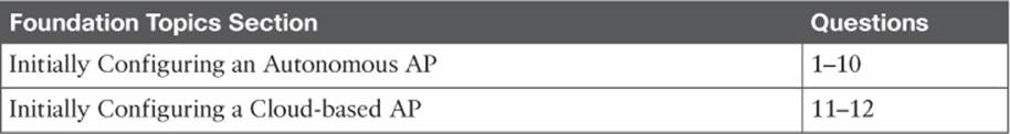
Table 9-1 “Do I Know This Already?” Section-to-Question Mapping
Caution
The goal of self-assessment is to gauge your mastery of the topics in this chapter. If you do not know the answer to a question or are only partially sure of the answer, you should mark that question as wrong for purposes of the self-assessment. Giving yourself credit for an answer you correctly guess skews your self-assessment results and might provide you with a false sense of security.
1. Suppose that you need to set up an autonomous AP so that it will offer three different SSIDs to clients. The AP will be connected to a wired network infrastructure. Which one of the following is a true statement about the AP?
a. It can support only one SSID, which must be carried over an access link.
b. It can support multiple SSIDs over an access link.
c. It can support multiple SSIDs over an 802.1Q trunk link.
d. An autonomous AP needs a centralized controller to support SSIDs.
2. Which one of the following is a true statement?
a. An autonomous AP cannot connect to a DS.
b. An autonomous AP connects through a centralized controller.
c. An autonomous AP operates in a standalone fashion.
d. None of these answers are correct.
3. Which of the following ports are available on an autonomous AP? (Choose all that apply.)
a. Console port
b. Service port
c. Ethernet port
d. Dynamic interface
4. After looking at a sticker on the back of an autonomous AP, you see MAC C4:7D:4F:12:34:56 listed. Which one of the following is a safe assumption?
a. The string of numbers is the 2.4-GHz radio base MAC address.
b. The string of numbers is the 5-GHz radio base MAC address.
c. The string of numbers is the Ethernet port MAC address.
d. All of the above are correct.
5. Which methods can be used to assign an IP address to an autonomous AP? (Choose all that apply.)
a. DHCP
b. Static through the CLI
c. TFTP
d. DNS
6. If the IP address of an autonomous AP is not yet known, which of the following methods could you use to find it? (Choose all that apply.)
a. DHCP server logs
b. CDP
c. AP console CLI
d. AP management GUI
7. In its default configuration, which of the following is true of an autonomous AP? (Choose all that apply.)
a. Both radios are enabled.
b. Both radios are disabled.
c. No SSIDs are configured.
d. One SSID (“Cisco”) is configured.
8. Which of the following are correct statements about autonomous AP configuration? (Choose all that apply.)
a. Each AP radio must offer an identical set of SSIDs.
b. Each AP radio can offer a unique set of SSIDs.
c. Each AP must be configured with the IP address of its controller.
d. An IP address must be configured on the Ethernet0 interface.
e. An IP address must be configured on the BVI1 interface.
9. To convert an autonomous AP into a lightweight AP, which of the following is needed? (Choose all that apply.)
a. Enter the convert lightweight command in the AP CLI
b. A TFTP or FTP server
c. An appropriate lightweight code image
d. An appropriate autonomous upgrade image
10. To upgrade an autonomous AP to lightweight mode, which one of the following initial command keywords should be used from the CLI?
a.upgrade download-sw
b.copy flash: tftp:
c.archive download-sw
d.download upgrade-sw
11. Which one of the following methods can you use to manage a Cisco Meraki AP?
a. Console port
b. CLI via Telnet
c. Web browser opened to the AP’s IP address
d. Web browser opened to the Cisco Meraki cloud
12. When a new Cisco Meraki AP is first powered on, it automatically connects with which one of the following?
a. A Cisco wireless LAN controller
b. A TFTP server located at 10.0.0.1
c. The Cisco Meraki cloud network
d. Nothing; as an autonomous AP, it waits for you to configure its IP address
Foundation Topics
Autonomous APs are commonly used in small networks, such as a small office or a remote site. Because the APs are self-contained and self-sufficient, they are fairly easy to set up and configure. The end result is a decentralized, distributed architecture, where each wireless AP touches the wired network independently. Each AP is configured and managed independently too, which can lead to a management nightmare as the number of APs grows.
You can think of an AP as a translational bridge, where frames from two dissimilar media are translated and then bridged at Layer 2. In simple terms, the AP is in charge of mapping a service set identifier (SSID) to a VLAN, or in 802.11 terms, mapping a basic service set (BSS) to a distribution system (DS). This is shown in Figure 9-1, where the AP connects a client that is associated to the SSID “Marketing” with the wired network on VLAN 10. On the wired side, the AP’s Ethernet port is connected to a switch port configured for access mode and mapped to VLAN 10.
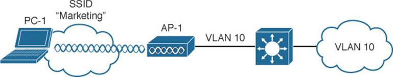
Figure 9-1 Bridging an SSID to a VLAN
This concept can be extended so that multiple VLANs are mapped to multiple SSIDs. To do this, the AP must be connected to the switch by a trunk link that carries the VLANs. In Figure 9-2, VLAN 10 and VLAN 20 are both trunked to the AP. The AP uses the 802.1Q tag to map the VLAN numbers to SSIDs. For example, VLAN 10 is mapped to SSID “Marketing,” while VLAN 20 is mapped to SSID “Engineering.”
![]()
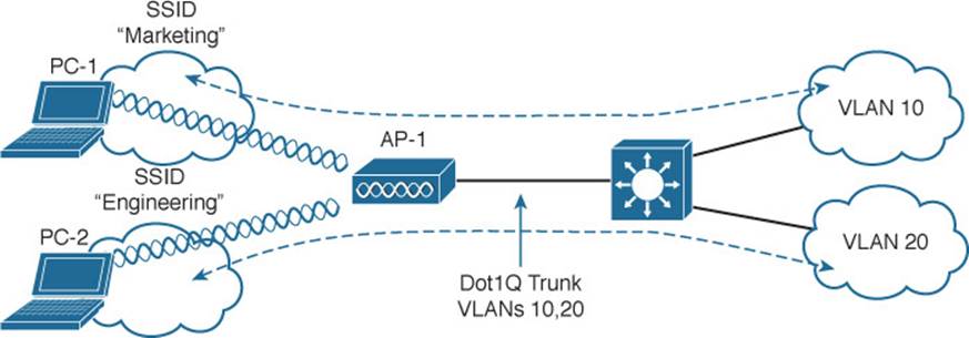
Figure 9-2 Bridging Multiple SSIDs to VLANs
In effect, when an AP uses multiple SSIDs, it is trunking VLANs over the air to wireless clients. In the 802.11 space, the VLAN tag is replaced by the SSID. The autonomous AP then becomes an extension of an access layer switch because it bridges SSIDs and VLANs right at the access layer.
Initially Configuring an Autonomous AP
As a wireless engineer, you will likely have to install and configure an autonomous AP. Many Cisco APs can operate in autonomous mode by running an IOS image—much like many other Cisco products. You can configure an AP through any of the following methods:
![]() A terminal emulator connected to the AP’s console port
A terminal emulator connected to the AP’s console port
![]() Telnet or Secure Shell (SSH) to the AP’s IP address
Telnet or Secure Shell (SSH) to the AP’s IP address
![]() Use a web browser to access a graphical user interface (GUI) at the AP’s IP address
Use a web browser to access a graphical user interface (GUI) at the AP’s IP address
As you read through this chapter, think about the different parameters you might have to configure on an autonomous AP. At a minimum, you would have to configure one or more SSIDs and some wireless security settings. In addition, you would have to set the transmit power level and channel number for each of the AP’s radios. Now think about your wireless network as it grows—manually configuring a handful of autonomous APs might not be difficult, but working out the channel reuse layout for 50 or 100 APs in the same building might become a nightmare.
Connecting the AP
Figure 9-3 shows the ports that are available on a typical access point. You should connect the Ethernet port to a switch port on the wired network. The console port can remain disconnected unless you need to use it. A sticker on the AP provides the model and serial numbers, as well as the Ethernet port’s MAC address.
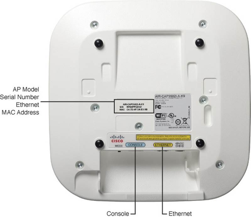
Figure 9-3 Ports Available on an Autonomous AP
By default, an AP will try to use Dynamic Host Configuration Protocol (DHCP) to request an IP address for itself. If it is successful, you can connect to it and interact with its GUI or command-line interface (CLI). If not, the AP will use the static IP address 10.0.0.1/26. You can also use the console port to configure a static IP address on the BVI1 interface of the AP, but it is usually more flexible and convenient to let it request an address on its own.
The AP’s IP address will not be readily visible because the AP has no way to display it, other than through its user interface and configuration. To find the IP address, you can query the DHCP server that assigned it and look for the AP’s MAC address.
Suppose that an AP has MAC address 00:22:bd:19:28:dd. From the output listed in Example 9-1, the MAC address is bound to IP address 192.168.199.44.
Example 9-1 Finding an Autonomous AP’s IP Address
Branch_Office# show ip dhcp binding
Bindings from all pools not associated with VRF:
IP address Client-ID/ Lease expiration Type
Hardware address/
User name
192.168.199.7 0020.6b77.9549 Infinite Manual
192.168.199.8 000e.3b00.b1a3 Infinite Manual
192.168.199.9 0004.00d0.378d Infinite Manual
192.168.199.14 0100.24f3.da9b.95 May 10 2015 01:09 AM Automatic
192.168.199.20 0170.f1a1.131c.48 May 09 2015 09:25 PM Automatic
192.168.199.23 0194.39e5.826c.38 May 09 2015 08:51 PM Automatic
192.168.199.24 0100.216a.0ac3.a0 May 09 2015 11:21 PM Automatic
192.168.199.34 0100.166f.6614.6d May 09 2015 09:33 PM Automatic
192.168.199.43 01cc.fe3c.4d66.49 May 09 2015 04:59 PM Automatic
192.168.199.44 0100.22bd.1928.dd May 10 2015 11:20 AM Automatic
Branch_Office#
As an alternative, you could also log in to the switch where the AP is connected and display detailed Cisco Discovery Protocol (CDP) neighbor information. Example 9-2 shows the output that reveals the IP address of the AP connected to interface GigabitEthernet1/0/1.
Example 9-2 Displaying CDP Neighbor Information to Find an Autonomous AP’s IP Address
Switch# show cdp neighbor gigabitethernet1/0/1 detail
-------------------------
Device ID: ap
Entry address(es):
IP address: 192.168.199.44
Platform: cisco AIR-CAP3702I-A-K9, Capabilities: Router Trans-Bridge
Interface: GigabitEthernet1/0/1, Port ID (outgoing port): GigabitEthernet0.1
Holdtime : 138 sec
Version :
Cisco IOS Software, C3700 Software (AP3G2-K9W8-M), Version 15.2(4)JB6, RELEASE SOFT-
WARE (fc1)
Technical Support: http://www.cisco.com/techsupport
Copyright (c) 1986-2014 by Cisco Systems, Inc.
Compiled Fri 22-Aug-14 11:52 by prod_rel_team
advertisement version: 2
Duplex: full
Power drawn: 15.400 Watts
Power request id: 52275, Power management id: 7
Power request levels are:16800 15400 13000 0 0
Management address(es):
An autonomous AP binds the IP address to its bridged-virtual interface (BVI), which is a logical interface used to bridge the physical wired and wireless interfaces. If you are connected to the AP’s console port, you can display the IP address with the show interface bvi1 command, as shown in Example 9-3.
Example 9-3 Displaying the BVI IP Address
ap# show interface bvi1
BVI1 is up, line protocol is up
Hardware is BVI, address is 0022.bd19.28dd (bia 0023.eb81.eb70)
Internet address is 192.168.199.44/24
MTU 1500 bytes, BW 54000 Kbit/sec, DLY 5000 usec,
reliability 255/255, txload 1/255, rxload 1/255
Encapsulation ARPA, loopback not set
ARP type: ARPA, ARP Timeout 04:00:00
[output truncated]
Initially Configuring the AP
By default, an autonomous AP has its radios disabled and does not have any SSIDs configured. This is done to prevent the new AP from interfering with any existing signals before you have a chance to configure it. This also prevents anyone from inadvertently discovering a wireless signal coming from the AP before you can secure it.
Perhaps the easiest method you can use to configure an autonomous AP is to use its web interface. Once you know the AP’s IP address, you can open a web browser to it. By default, you can leave the username blank and enter the password as Cisco. The Summary or home page, as shown inFigure 9-4, displays a summary of associated clients, the AP’s Ethernet and radio interfaces, and an event log.
![]()
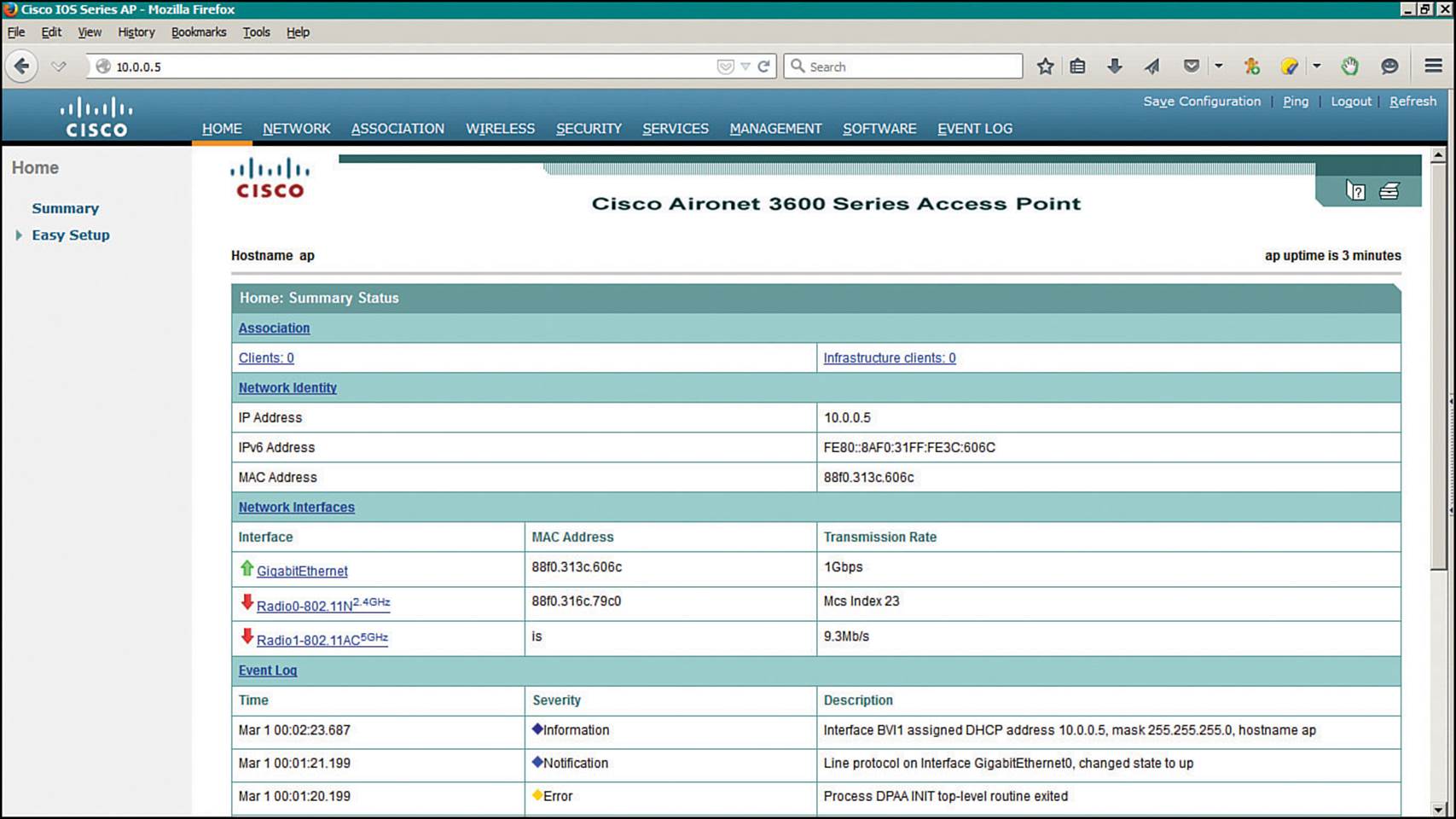
Figure 9-4 Autonomous AP Web Page
At the CCNA Wireless level, Cisco expects candidates to be able to perform basic configuration tasks on autonomous APs. Therefore, you should be familiar with only the Summary and Easy Setup menus at the upper-left corner of the web page, as found under the Home tab.
To use the Easy Setup page, as shown in Figure 9-5, you need to enter the following information about the AP:
![]() Hostname
Hostname
![]() Method of IP address assignment
Method of IP address assignment
![]() For a static address: IP address, subnet mask, default gateway
For a static address: IP address, subnet mask, default gateway
![]() An administrative username and password
An administrative username and password
![]() SNMP community
SNMP community
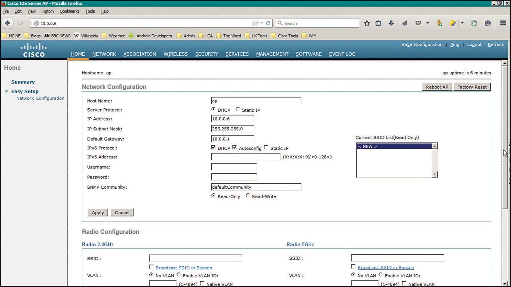
Figure 9-5 Autonomous AP Easy Setup Page
You will also need to set some parameters for the 2.4- and 5-GHz radios, which are configured independently in the bottom portion of the Easy Setup page, as shown in Figure 9-6. Enter the name of the first SSID that the AP will provide to wireless users. If the AP will support only a single SSID that is mapped to a single VLAN, select the No VLAN radio button. Otherwise, select Enable VLAN ID and enter the VLAN number for the SSID.
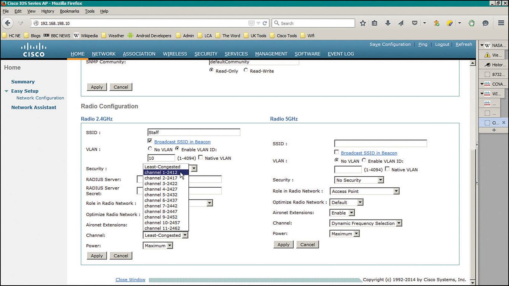
Figure 9-6 Easy Setup Radio Configuration Page
Next, select the type of wireless security you want to offer on the SSID. The Security menu options are described in further detail in Chapter 14, “Wireless Security Fundamentals.”
By default, each radio is configured to operate in the Access Point role, so that the AP offers an active BSS. You can select one of the following roles instead from the Role in Radio Network drop-down menu:
![]() Repeater—The AP will associate with another nearby AP automatically, to repeat or extend that AP’s cell coverage. The Ethernet port will be disabled.
Repeater—The AP will associate with another nearby AP automatically, to repeat or extend that AP’s cell coverage. The Ethernet port will be disabled.
![]() Root Bridge—The AP uses its Ethernet port to connect to bridge the wired network to a remote wireless bridge over a point-to-point or point-to-multipoint link. No wireless clients will be allowed to associate.
Root Bridge—The AP uses its Ethernet port to connect to bridge the wired network to a remote wireless bridge over a point-to-point or point-to-multipoint link. No wireless clients will be allowed to associate.
![]() Non-Root Bridge—The AP will act as a remote wireless bridge and will connect to a root bridge AP over a wireless link.
Non-Root Bridge—The AP will act as a remote wireless bridge and will connect to a root bridge AP over a wireless link.
![]() Workgroup Bridge—The AP will use one radio to associate with a nearby Cisco access point, as if it is a wireless client. The AP bridges between its radio and its Ethernet port. You can use an AP in workgroup bridge (WGB) mode to provide wireless client capability to wired-only devices.
Workgroup Bridge—The AP will use one radio to associate with a nearby Cisco access point, as if it is a wireless client. The AP bridges between its radio and its Ethernet port. You can use an AP in workgroup bridge (WGB) mode to provide wireless client capability to wired-only devices.
![]() Universal Workgroup Bridge—The AP will act as a workgroup bridge to associate with Cisco and non-Cisco access points.
Universal Workgroup Bridge—The AP will act as a workgroup bridge to associate with Cisco and non-Cisco access points.
![]() Scanner—The AP will use its radio to scan channels and collect data.
Scanner—The AP will use its radio to scan channels and collect data.
![]() Spectrum—The AP will devote its radios to scanning the frequency band and collecting information about RF usage and interference.
Spectrum—The AP will devote its radios to scanning the frequency band and collecting information about RF usage and interference.
The Optimize Radio Network drop-down menu enables you to select how the AP will optimize its cell for wireless clients. By default, the AP will offer data rates that can provide good range and throughput. You can select Throughput to leverage higher data rates at the expense of cell range or Range to require the lowest data rate for maximum cell range.
Aironet Extensions are Cisco proprietary information elements that Cisco APs can use to interact with Cisco-compatible wireless clients. For example, an AP can provide information about its current client load so that potential clients can choose the least busy AP. Aironet extensions are enabled by default.
At the bottom of the Radio Configuration page, you can select the channel that the AP will use. By default, the channel is set to Least-Congested (2.4 GHz) and Dynamic Frequency Selection (5 GHz) so that the AP will scan and find a channel that it considers to be most viable in its current location. This is not always a best practice because the AP will choose any channel number that it sees fit. That means the 2.4-GHz radio might end up on channel 3 if channels 1 and 11 are already in use. A better practice is to select a specific channel for each radio instead. Each radio has a transmit power setting, too—each defaults to its maximum power rating or a specific dBm level that you select.
Click Apply for the settings to take effect.
At this point of the configuration, you do not necessarily have a functional AP because the radios are still disabled. To enable a radio, navigate to the AP’s home page and select Network > Network Interface > Radio0-802.11N2.4GHz or Radio1-802.11N5GHz. Click the Settings tab to open it, and then select the Enable button next to Enable Radio.
As you are configuring an autonomous AP, keep in mind that the changes you make are applied to the running configuration and will not be saved if the AP loses power or reboots. Click the Save Configuration link in the upper-right corner of the screen to save the whole AP configuration into nonvolatile memory.
Tip
Although the WIFUND 200-355 exam blueprint topics are limited to the initial “easy” configuration tabs on an autonomous AP, you will need to be proficient with many more complex features on lightweight APs as part of a larger, unified wireless network. Don’t worry; lightweight APs (LAPs) and unified networks are covered in detail throughout the remainder of the book.
Once the initial configuration is complete, you may want to configure or monitor other features that the autonomous AP offers. Table 9-2 lists the tabs that are displayed across the top of the GUI, along with common features found in each.
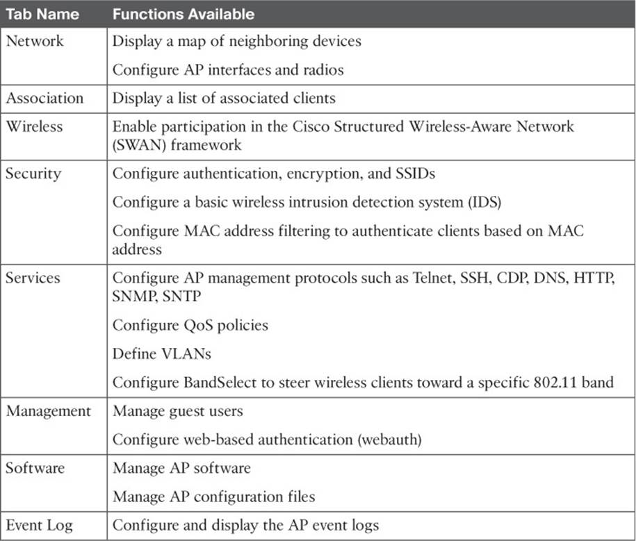
Table 9-2 Cisco Autonomous AP Configuration Tabs and Their Functions
Some autonomous AP features are not accessible from the GUI and must be configured or monitored from the CLI instead. For example, the ClientLink feature can be used to enable transmit beamforming (TxBF) to improve communication with each individual client. It must be configured using the CLI through Telnet or SSH by entering the beamform ofdm radio interface configuration command.
Upgrading an Autonomous AP
Occasionally you may need to upgrade the IOS software running on an autonomous AP. You can perform software upgrades from a web browser that is opened to the AP’s IP address. Download the new autonomous mode image file from Cisco.com onto the machine, then click the Softwaretab and the Software Upgrade link, as shown in Figure 9-7. Click the Browse button to locate the new software image, then click the Upgrade button to begin the upgrade process. Once the upgrade is complete, the AP must be rebooted so that it can begin running the new image.
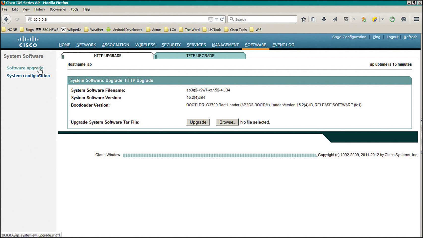
Figure 9-7 Autonomous AP Software Upgrade Page
Autonomous APs can be useful in remote sites, small offices, or homes where centralized management is not necessary or practical. In larger environments, a centralized or unified approach is more common. Sometimes you might face a hybrid scenario, where some legacy autonomous APs still exist in a centrally managed network. In that case, you might need to either replace the AP hardware or convert its software image so that it can join the wireless controllers that manage the network. In fact, Cisco expects a CCNA Wireless engineer to know how to convert an autonomous AP to a “lightweight” version that can join a controller.
To convert an AP, you can use one of the following methods, which are described in the subsequent sections:
![]() Use the Cisco Prime Infrastructure application; all wireless controllers and lightweight APs can be monitored and managed from this one application. The autonomous AP must first be managed, then it can be converted. Cisco Prime Infrastructure is discussed in Chapter 18, “Managing Cisco Wireless Networks,” but using it to convert autonomous APs is not covered on the CCNA Wireless exam.
Use the Cisco Prime Infrastructure application; all wireless controllers and lightweight APs can be monitored and managed from this one application. The autonomous AP must first be managed, then it can be converted. Cisco Prime Infrastructure is discussed in Chapter 18, “Managing Cisco Wireless Networks,” but using it to convert autonomous APs is not covered on the CCNA Wireless exam.
![]() Use the archive command from the autonomous AP’s CLI.
Use the archive command from the autonomous AP’s CLI.
You can use the CLI to upgrade the IOS image on an autonomous AP and convert it to lightweight mode. You will also need a TFTP or FTP server along with the appropriate lightweight code image. The process is simple—save the AP’s configuration, then use the following command:
archive download-sw /overwrite /force-reload {tftp:|ftp:}//location/image-name
The lightweight image will be downloaded such that it overwrites the current autonomous IOS image, then the AP will reload and run the new image. Example 9-4 demonstrates the conversion process. The TFTP server is located at 10.0.0.99, and the new lightweight image is named ap3g2-k9w8-tar.153-3.JBB1.tar. If you are using an FTP server, you should specify the FTP username and password that the AP will use with the following commands:
ap(config)# ip ftp username username
ap(config)# ip ftp password password
Tip
Cisco AP image filenames can be difficult to identify. If a filename contains k9w8, as in Example 9-4, it is a lightweight image. If it contains k9w7, it is an autonomous image.
![]()
Example 9-4 Manually Converting an Autonomous AP
ap# archive download-sw /overwrite /reload tftp://10.0.0.99/ap3g2-k9w8-tar.153-3.JBB1.
tar
examining image...
Loading ap3g2-k9w8-tar.153-3.JBB1.tar from 10.0.0.99 (via BVI1): !
extracting info (282 bytes)
Image info:
Version Suffix: k9w8-.153-3.JBB1
Image Name: ap3g2-k9w8-tar.153-3.JBB1
Version Directory: ap3g2-k9w8-tar.153-3.JBB1
Ios Image Size: 9421312
Total Image Size: 9615872
Image Feature: WIRELESS LAN|LWAPP
Image Family: C3700
Wireless Switch Management Version: 8.0.120.0
Extracting files...
ap3g2-k9w8-tar.153-3.JBB1/ (directory) 0 (bytes)O
ap3g2-k9w8-tar.153-3.JBB1/html/ (directory) 0 (bytes)
[output omitted for clarity]
extracting info.ver (282 bytes)
[OK - 9615360 bytes]
Deleting current version: flash:...done.
New software image installed in flash:/ ap3g2-k9w8-tar.153-3.JBB1
Configuring system to use new image...done.
Requested system reload
archive download: takes 107 seconds
Initially Configuring Cloud-based APs
A cloud-based AP is somewhat similar to an autonomous AP; once configured, it can operate independently to provide fully functional wireless LANs. However, you can configure and manage one or more cloud-based APs from the Cisco Meraki cloud on the Internet.
Meraki APs have only a connector for a power supply and an RJ-45 connector for an Ethernet connection. There is no console port for local administrative access. The initial configuration is fairly straightforward—connect a new AP to the wired network and plug in the AP’s power source. As the AP boots up, it will automatically obtain an IP address through DHCP and will contact the Cisco Meraki cloud network for further instructions. From that point on, you perform all configuration and monitoring through a browser that is pointed to the cloud.
Tip
If, for some reason, the AP cannot join the Meraki cloud, it will bring up a local WLAN that you can connect to for more information. Once you connect and open a browser to the AP’s IP address, you will see an explanation about why the AP is failing to join the cloud.
At this point, you should browse to https://meraki.cisco.com and click the Login link. The goal is to access the Meraki Dashboard, as shown in Figure 9-8. If you do not already have an account, click the Create an Account link. Otherwise, you can enter your username and password to log in.
![]()
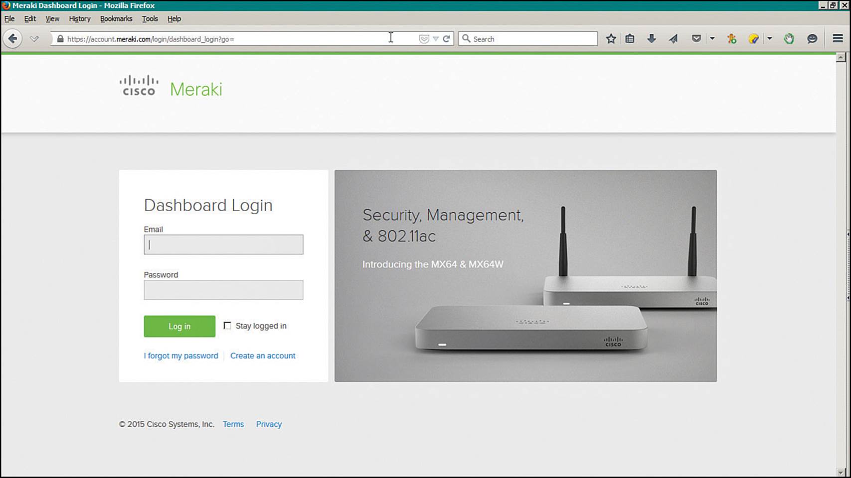
Figure 9-8 Accessing the Cisco Meraki Dashboard
Next, you will need to associate APs with your Dashboard account. To do that, select Network-wide > Configure > Add Devices, as shown in Figure 9-9, then click the Claim button. Then enter each AP serial number in the list that is shown in Figure 9-10 and click the Claim button.
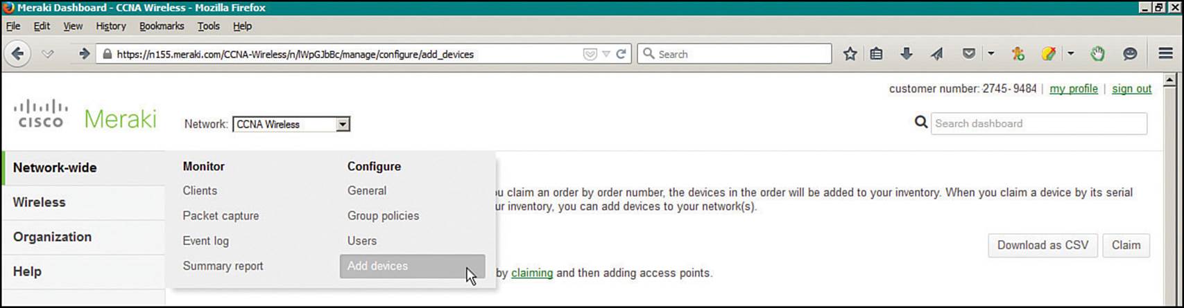
Figure 9-9 Adding New Cisco Meraki APs
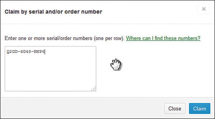
Figure 9-10 Listing Cisco Meraki APs to Claim
Tip
As you navigate the Cisco Meraki Dashboard, be aware that every function is organized with Monitor and Configuration tasks.
Next, you can configure one or more SSIDs on the AP. Select Wireless > Configure > SSIDs as shown in Figure 9-11. The list of SSIDs is displayed in the Configuration Overview: SSIDs page that is shown in Figure 9-12. The first SSID is named “Guest” by default, and only one SSID is enabled by default. You can define up to 15 SSIDs.
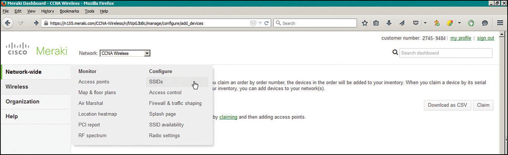
Figure 9-11 Preparing to Configure SSIDs on a Cisco Meraki AP
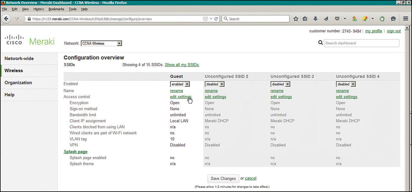
Figure 9-12 Listing SSIDs to Configure
You can click the Rename link to change the name of an existing SSID or click the Edit Settings link to configure the SSID. Figures 9-13 and 9-14 show the top and bottom portions of the page that is displayed when Edit Settings has been clicked under the Guest SSID. In the top portion of the page, you can configure security parameters that control access to the SSID. Further down the page, you can configure IP addressing, VLAN tagging, and wireless parameters. In Figure 9-14, the AP is configured to offer multiple SSIDs that are mapped to VLANs. The AP is configured for Bridge mode, which enables a trunk link and maps SSIDs to VLAN numbers. The Guest SSID is mapped to VLAN 10.
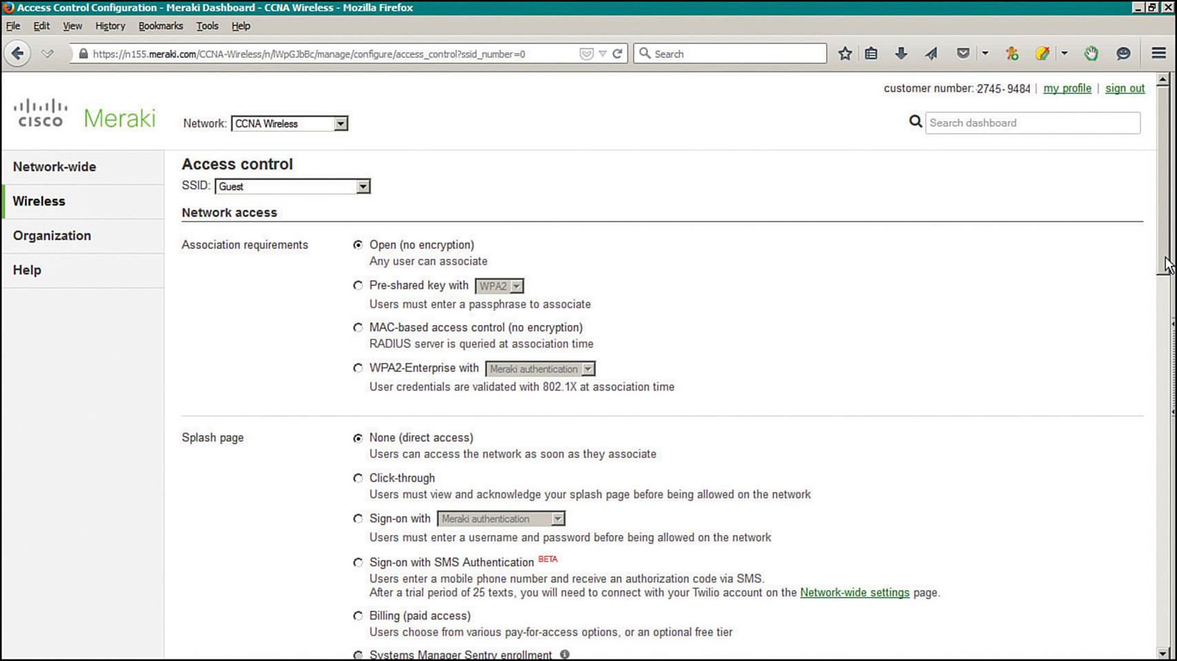
Figure 9-13 Editing Security Settings for an SSID
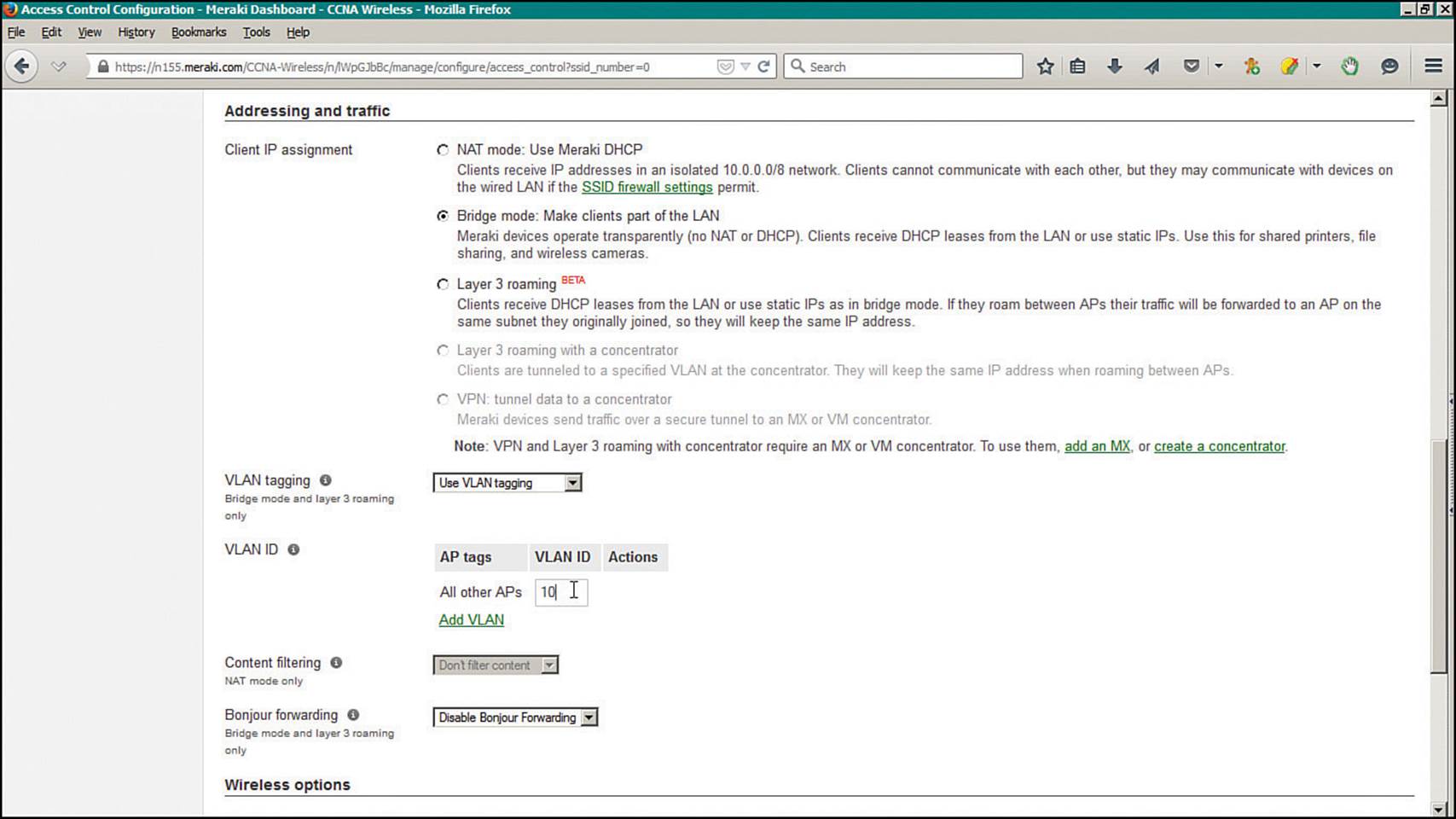
Figure 9-14 Editing IP Addressing and VLAN Settings for an SSID
By default, the AP will bridge the wireless and wired LANs, just as an autonomous AP would do. In this case, client roaming is constrained to a single VLAN where all of the cloud-based APs are connected. You can leverage the Layer 3 roaming feature instead, to scale roaming to include APs that are located on different VLANs. As a user roams, traffic will be tunneled from the AP where the user originally associated to another AP where the user currently resides.
Once you are finished configuring the SSID, click the Save Changes button. The configuration changes will be pushed out to the AP from the Cisco Meraki cloud network.
You can use the Cisco Meraki cloud-based Dashboard to monitor your APs and to configure some robust features. Table 9-3 lists the tabs that are available along the left side of the Dashboard page.
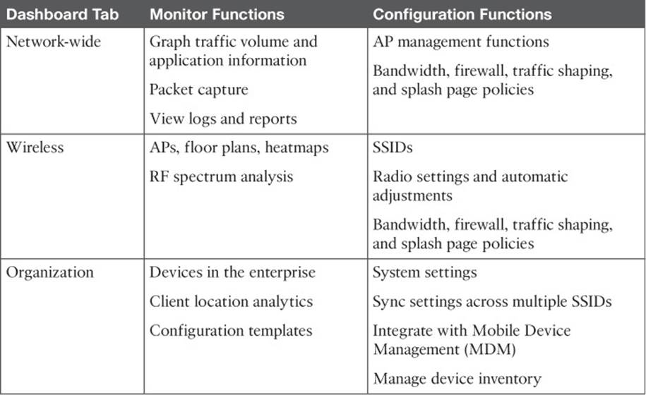
Table 9-3 Cisco Meraki Dashboard Tabs and Their Functions
Tip
When Cisco Meraki APs boot up and contact the cloud network for the first time, their firmware is automatically upgraded to the most current level. After that, firmware is pushed out from the cloud network to the APs automatically, according to a preset schedule. You can define the schedule by selecting Network-wide > Configure > General and scrolling down to the Firmware Upgrades section of the page.
Exam Preparation Tasks
As mentioned in the section, “How to Use This Book,” in the Introduction, you have a couple of choices for exam preparation: the exercises here, Chapter 21, “Final Review,” and the exam simulation questions on the DVD.
Review All Key Topics
Review the most important topics in this chapter, noted with the Key Topic icon in the outer margin of the page. Table 9-4 lists a reference of these key topics and the page numbers on which each is found.
![]()
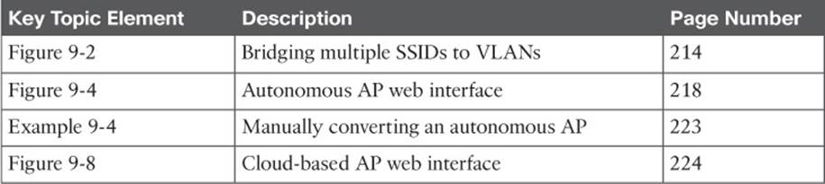
Table 9-4 Key Topics for Chapter 9
Define Key Terms
Define the following key term from this chapter and check your answer in the glossary:
autonomous AP
All materials on the site are licensed Creative Commons Attribution-Sharealike 3.0 Unported CC BY-SA 3.0 & GNU Free Documentation License (GFDL)
If you are the copyright holder of any material contained on our site and intend to remove it, please contact our site administrator for approval.
© 2016-2026 All site design rights belong to S.Y.A.