CCNA Wireless 200-355 Official Cert Guide (2016)
Chapter 15. Configuring a WLAN
This chapter covers the following topics:
![]() WLAN Overview—This section provides a review of WLAN concepts and rules of thumb for their use.
WLAN Overview—This section provides a review of WLAN concepts and rules of thumb for their use.
![]() Configuring a WLAN—This section covers the steps necessary to create a WLAN on a Cisco wireless LAN controller.
Configuring a WLAN—This section covers the steps necessary to create a WLAN on a Cisco wireless LAN controller.
This chapter covers the following exam topics:
![]() 3.3—Describe AP and WLC management access connections
3.3—Describe AP and WLC management access connections
![]() 3.3c—Management via wireless
3.3c—Management via wireless
![]() 4.4—Describe and configure the components of a wireless LAN access for client connectivity using GUI only
4.4—Describe and configure the components of a wireless LAN access for client connectivity using GUI only
A wireless LAN controller (WLC) sits somewhere between wireless access points (APs) and a wired network. In this chapter, you learn how to define and tune a wireless LAN (WLAN) to reach devices on each of those networks. In addition, based on the concepts you learned in Chapter 14, “Wireless Security Fundamentals,” you will be able to configure basic security parameters for the WLAN.
“Do I Know This Already?” Quiz
The “Do I Know This Already?” quiz allows you to assess whether you should read this entire chapter thoroughly or jump to the “Exam Preparation Tasks” section. If you are in doubt about your answers to these questions or your own assessment of your knowledge of the topics, read the entire chapter. Table 15-1 lists the major headings in this chapter and their corresponding “Do I Know This Already?” quiz questions. You can find the answers in Appendix A, “Answers to the ‘Do I Know This Already?’ Quizzes.”
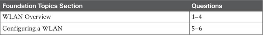
Table 15-1 “Do I Know This Already?” Section-to-Question Mapping
Caution
The goal of self-assessment is to gauge your mastery of the topics in this chapter. If you do not know the answer to a question or are only partially sure of the answer, you should mark that question as wrong for purposes of the self-assessment. Giving yourself credit for an answer you correctly guess skews your self-assessment results and might provide you with a false sense of security.
1. Which two of the following things are bound together when a new WLAN is created?
a. VLAN
b. AP
c. Controller interface
d. SSID
2. What is the maximum number of WLANs you can configure on a Cisco wireless controller?
a. 8
b. 16
c. 512
d. 1024
3. What is the maximum number of WLANs that can be enabled on a Cisco lightweight AP?
a. 8
b. 16
c. 512
d. 1024
4. Which one of the following is a limiting factor when multiple WLANs are offered on an AP and its radio channel?
a. The speed of the controller interface
b. The airtime used for each WLAN’s beacons
c. Co-channel interference between WLANs on the AP
d. The number of APs joined to the controller
5. Which of the following parameters are necessary when creating a new WLAN with the controller GUI? (Choose all that apply.)
a. SSID
b. VLAN number
c. Interface
d. BSSID
e. IP subnet
6. The WLAN ID number is advertised to wireless clients. True or false?
a. True
b. False
Foundation Topics
WLAN Overview
Recall from Chapter 8, “Understanding Cisco Wireless Architectures,” that a wireless LAN controller and an access point work in concert to provide network connectivity to wireless clients. From a wireless perspective, the AP advertises a service set identifier (SSID) for the client to join. From a wired perspective, the controller connects to a virtual LAN (VLAN) through one of its dynamic interfaces. To complete the path between the SSID and the VLAN, as illustrated in Figure 15-1, you must first define a WLAN on the controller.
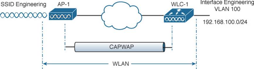
Figure 15-1 Connecting Wired and Wireless Networks with a WLAN
The controller will bind the WLAN to one of its interfaces and then push the WLAN configuration out to all of its APs by default. From that point on, wireless clients will be able to learn about the new WLAN and will be able to probe and join the new basic service set (BSS).
Like VLANs, you can use WLANs to segregate wireless users and their traffic into logical networks. Users associated with one WLAN cannot cross over into another one unless their traffic is bridged or routed from one VLAN to another through the wired network infrastructure.
Before you begin to create new WLANs, it is usually wise to plan your wireless network first. In a large enterprise, you might have to support a wide variety of wireless devices, user communities, security policies, and so on. You might be tempted to create a new WLAN for every occasion, just to keep groups of users isolated from each other or to support different types of devices. Although that is an appealing strategy, you should be aware of two limitations:
![]() Cisco controllers support a maximum of 512 WLANs, but only 16 of them can be actively configured on an AP. The Cisco 2504 Wireless Controller is limited to a maximum of 16 WLANs.
Cisco controllers support a maximum of 512 WLANs, but only 16 of them can be actively configured on an AP. The Cisco 2504 Wireless Controller is limited to a maximum of 16 WLANs.
![]() Advertising each WLAN uses up valuable airtime.
Advertising each WLAN uses up valuable airtime.
Every AP must broadcast beacon management frames at regular intervals to advertise the existence of a BSS. Because each WLAN is bound to a BSS, each WLAN must be advertised with its own beacons. Beacons are normally sent ten times per second, or once every 100 ms, at the lowest mandatory data rate. The more WLANs you have created, the more beacons you will need to announce them.
Even further, the lower the mandatory date rate, the more time each beacon will take to be transmitted. The end result is this: If you create too many WLANs, a channel can be starved of any usable airtime. Clients will have a hard time transmitting their own data because the channel is overly busy with beacon transmissions. As a rule of thumb, always limit the number of WLANs to five or fewer; a maximum of three WLANs is best.
Configuring a WLAN
By default, a controller has no configuration and therefore no WLANs. Before you create a new WLAN, think about the following parameters it will need to have:
![]() SSID
SSID
![]() Controller interface and VLAN number
Controller interface and VLAN number
![]() Type of wireless security needed
Type of wireless security needed
As you work through this chapter, you will create the appropriate dynamic controller interface to support the new WLAN, then you will enter the necessary WLAN parameters. Both the centralized and converged wireless architectures are covered, as you can use a similar GUI for each type of WLC.
Configuring a RADIUS Server
If your new WLAN will use a security scheme that requires a RADIUS server, you need to define the server first. On a centralized controller, select Security > AAA > RADIUS > Authentication to see a list of servers that have already been configured, as shown in Figure 15-2. If multiple servers are defined, the controller will try them in sequential order. Click New to create a new server.
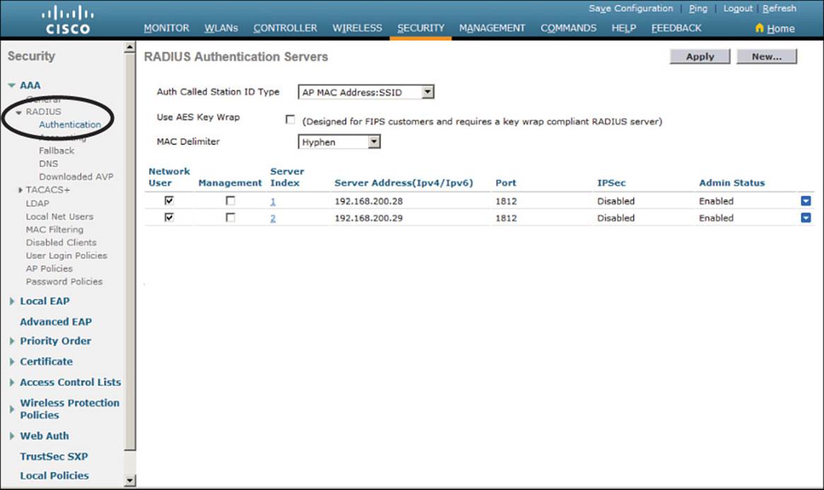
Figure 15-2 Displaying the List of RADIUS Authentication Servers
Next, enter the server’s IP address, shared secret key, and port number, as shown in Figure 15-3. Because the controller already had two other RADIUS servers configured, the server at 192.168.200.30 will be index number 3. Be sure to set the server status to Enabled so that the controller can begin using it. At the bottom of the page, you can select the type of user that will be authenticated with the server. Check Network User to authenticate wireless clients or Management to authenticate wireless administrators that will access the controller’s management functions. ClickApply to complete the server configuration.
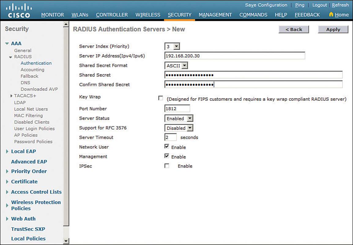
Figure 15-3 Configuring a New RADIUS Server
The process on a converged controller is similar, except that RADIUS servers are put into groups, then the group is applied as part of an authentication method list. The method list is used for authentication in any WLANs that are configured. Use the following steps to create a new RADIUS server.
Step 1. Select Configuration > Security.
Step 2. Under Security > AAA > Radius > Servers, click the New button to create a new RADIUS server entry. Enter the server’s name, IP address, and shared secret key string. Repeat this step to create any further RADIUS servers.
Step 3. Create a RADIUS server group by selecting Security > AAA > Server Groups > Radius. Move desired servers from the Available Servers list to the Assigned Servers list.
Step 4. Select Security > AAA > Method Lists > Authentication and define a new method that uses the RADIUS server. Move desired server groups from the Available Server Groups list to the Assigned Server Groups list.
Creating a Dynamic Interface
In Chapter 10, “Implementing Controller-based Deployments,” you learned about the different types of controller interfaces. A dynamic interface is used to connect the controller to a VLAN on the wired network. When you create a WLAN, you will bind the dynamic interface (and VLAN) to a wireless network.
To create a new dynamic interface on a centralized controller, navigate to Controller > Interfaces. You should see a list of all the controller interfaces that are currently configured. Click the New button to define a new interface. Enter a name for the interface and the VLAN number it will be bound to. In Figure 15-4, the interface named Engineering is mapped to wired VLAN 100. Click the Apply button.
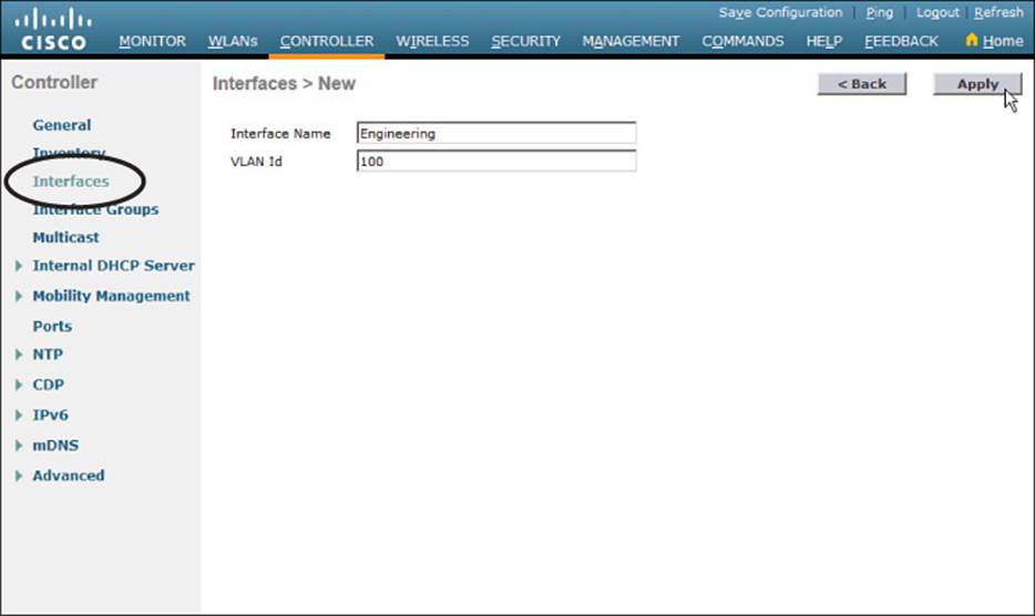
Figure 15-4 Defining a Dynamic Interface Name and VLAN ID on a Centralized Controller
Next, enter the IP address, subnet mask, and gateway address for the interface. You should also define primary and secondary DHCP server addresses that the controller will use when it relays DHCP requests from clients that are bound to the interface. Figure 15-5 shows how interface Engineering has been configured with IP address 192.168.100.10. Click the Apply button to complete the interface configuration and return to the list of interfaces.
![]()
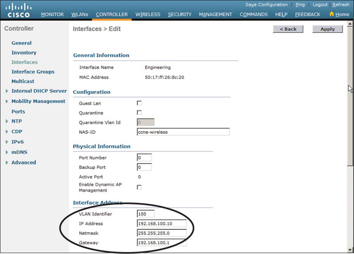
Figure 15-5 Editing the Dynamic Interface Parameters on a Centralized Controller
The process is similar on a converged controller. Create the interface by selecting Configuration > Controller > System > VLAN > Layer2 VLAN and entering a VLAN number and name as shown in Figure 15-6. In essence, you are creating a VLAN on the switch that is hosting the WLC.
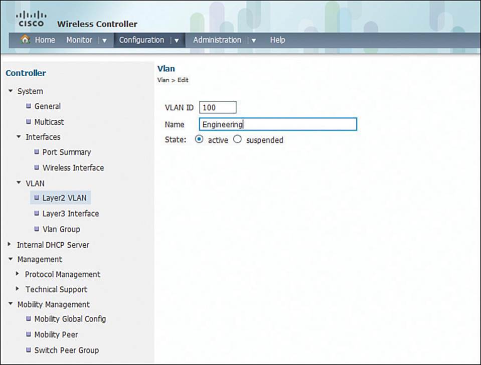
Figure 15-6 Defining a VLAN on a Converged Controller
Next, the dynamic interface needs a way to bring Layer 3 connectivity to the Layer 2 VLAN. Select Configuration > System > VLAN > Layer3 Interface, then click New. Enter the interface description, IP addressing information, and a DHCP server address as shown in Figure 15-7.
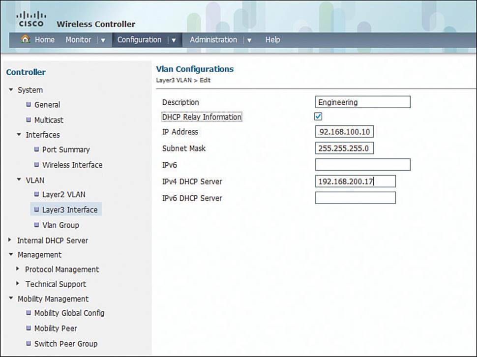
Figure 15-7 Defining a Dynamic VLAN Interface on a Converged Controller
Creating a New WLAN
You can display a list of the currently defined WLANs by selecting WLANs from the top menu bar. In Figure 15-8, the controller has one WLAN called guest already defined. You can create a new WLAN by selecting Create New from the drop-down menu and then clicking the Go button.
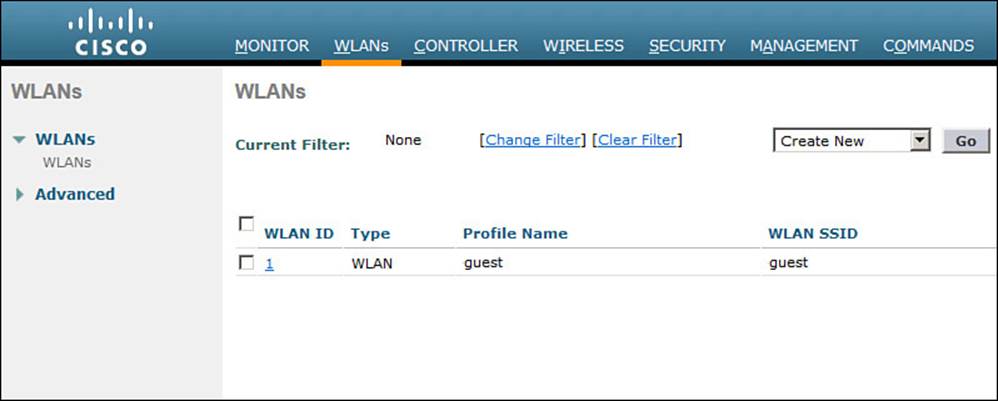
Figure 15-8 Displaying a List of WLANs
You can display the same list of WLANs on a converged controller by selecting Configuration > Wireless > WLAN > WLANs. Click New to create a new WLAN or select an existing WLAN from the list to edit its parameters.
Next, enter a descriptive name as the profile name and the SSID text string. In Figure 15-9, the profile name and SSID are identical, just to keep things straightforward. The ID number is used as an index into the list of WLANs that are defined on the controller. The ID number becomes useful when you use templates in Prime Infrastructure (PI) to configure WLANs on multiple controllers at the same time.
![]()
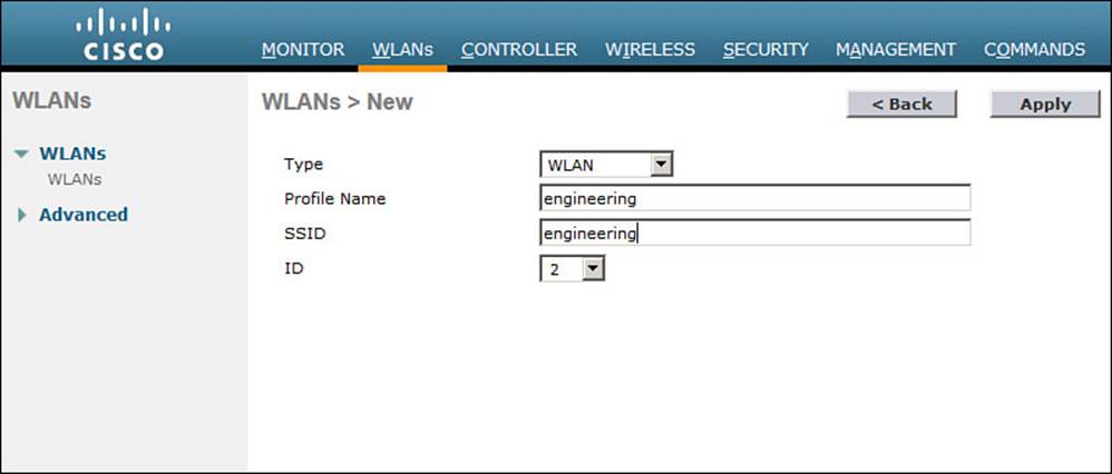
Figure 15-9 Creating a New WLAN
Tip
WLAN templates are applied to specific WLAN ID numbers on controllers. The WLAN ID is only locally significant and is not passed between controllers. As a rule, you should keep the sequence of WLAN names and IDs consistent across multiple controllers so that any configuration templates you use in the future will be applied to the correct WLANs.
Click the Apply button to create the new WLAN. The next page will allow you to edit four categories of parameters, corresponding to the tabs across the top as shown in Figure 15-10. On a converged controller, you will have to select the newly created WLAN again from the list of WLANs. By default, the General tab is selected.
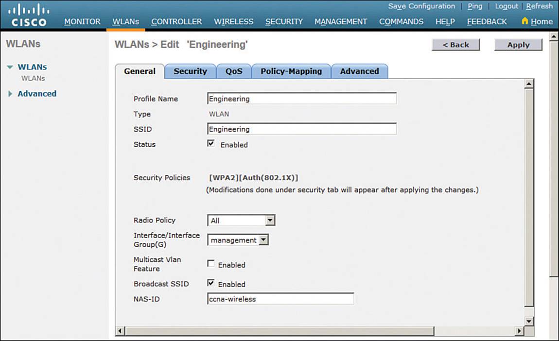
Figure 15-10 Configuring the General WLAN Parameters
You can control whether the WLAN is enabled or disabled with the Status check box. Even though the General page shows a specific security policy for the WLAN (the default WPA2 with 802.1x), you can make changes in a later step through the Security tab.
Under Radio Policy, select the type of radios that will offer the WLAN. By default, the WLAN will be offered on all radios that are joined with the controller. You can select a more specific policy with 802.11a only, 802.11a/g only, 802.11g only, or 802.11b/g only. For example, if you are creating a new WLAN for devices that have only a 2.4-GHz radio, it probably does not make sense to advertise the WLAN on both 2.4- and 5-GHz AP radios.
Next, select the controller interface that will be bound to the WLAN. The drop-down list contains all the interface names that are available. In Figure 15-10, the new engineering WLAN will be bound to the Engineering interface.
Finally, use the Broadcast SSID check box to select whether the APs should broadcast the SSID name in the beacons. Broadcasting SSIDs is usually more convenient for users, because their devices can learn and display the SSID names automatically. In fact, most devices actually need the SSID in the beacons to understand that the AP is still available for that SSID. Hiding the SSID name, by not broadcasting it, does not really provide any worthwhile security. Instead, it just prevents user devices from discovering an SSID and trying to use it as a default network.
Configuring WLAN Security
Select the Security tab to configure the security settings. By default, the Layer 2 security tab is selected. From the Layer 2 Security drop-down menu, select the appropriate security scheme to use. Table 15-2 lists the types that are available. You can also check the MAC Filtering check box to use client MAC addresses as authentication credentials.
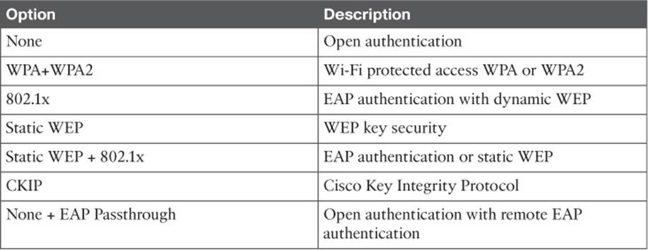
Table 15-2 Layer 2 WLAN Security Types
In Figure 15-11, WPA+WPA2 security is selected. In the remainder of the page, you can set parameters that are specific to the security scheme. For example, WPA2 with AES is used, but WPA and TKIP are not.
![]()
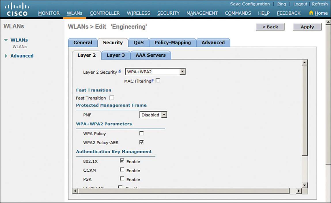
Figure 15-11 Configuring Layer 2 WLAN Security
If you choose a Layer 2 security scheme that requires a RADIUS server, the controller will use the global list of servers you have defined under Security > AAA > RADIUS > Authentication. You can override that list by identifying up to three specific RADIUS servers in the WLAN configuration. Display the AAA Servers tab, then under each server, you can select a specific server IP address from the drop-down menu of globally defined servers. Servers 1, 2, and 3 are tried in sequential order until one of them responds. In Figure 15-12, Server 1 is being set from a list of servers at 192.168.200.28, 192.168.200.29, and 192.168.200.30.
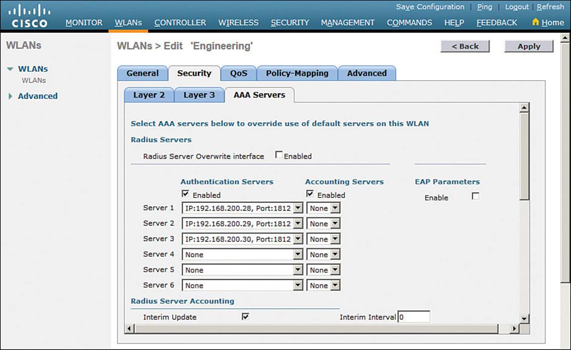
Figure 15-12 Selecting RADIUS Servers for WLAN Authentication
A converged controller is configured similarly, except that a method list is used to specify the authentication servers. Method lists are configured under Configuration > Security > AAA > Method Lists.
By default, a centralized controller will contact a RADIUS server from its management interface. You can override this behavior by checking the box next to Radius Server Overwrite Interface, so that the controller sources RADIUS requests from the dynamic interface that is associated with the WLAN.
Configuring WLAN QoS
Display the QoS tab to configure quality of service settings for the WLAN, as shown in Figure 15-13. By default, the controller will consider all frames in the WLAN to be normal data, to be handled in a “best effort” manner. You can set the Quality of Service (QoS) drop-down menu to classify all frames in one of the following ways:
![]() Platinum (voice)
Platinum (voice)
![]() Gold (video)
Gold (video)
![]() Silver (best effort)
Silver (best effort)
![]() Bronze (background)
Bronze (background)
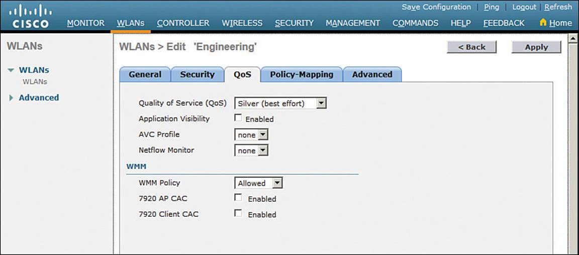
Figure 15-13 Configuring QoS Settings
You can also set the Wi-Fi Multimedia (WMM) policy, call admission control (CAC) policies, and bandwidth parameters on the QoS page.
Configuring Advanced WLAN Settings
Finally, display the Advanced tab to configure a variety of advanced WLAN settings. From the page shown in Figure 15-14, you can enable functions such as coverage hole detection, peer-to-peer blocking, client exclusion, client load limits, and so on.
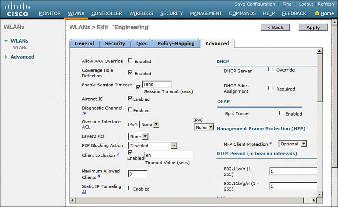
Figure 15-14 Configuring Advanced WLAN Settings
Although most of the advanced settings are beyond the scope of the CCNA Wireless level, you should be aware of a few defaults that might affect your wireless clients.
By default, client sessions with the WLAN are limited to 1800 seconds (30 minutes). Once that session time expires, a client will be required to reauthenticate. This setting is controlled by the Enable Session Timeout check box and the Timeout field.
A controller maintains a set of security policies that are used to detect potentially malicious wireless clients. If a client exhibits a certain behavior, the controller can exclude it from the WLAN for a period of time. By default, all clients are subject to the policies configured under Security >Wireless Protection Policies > Client Exclusion Policies. These policies include excessive 802.11 association failures, 802.11 authentication failures, 802.1x authentication failures, web authentication failures, and IP address theft or reuse. Offending clients will be automatically excluded or blocked for 60 seconds, as a deterrent to attacks on the wireless network.
Tip
Is 60 seconds really enough time to deter an attack coming from a wireless client? In the case of a brute-force attack, where passwords are guessed from a dictionary of possibilities, 60 seconds is enough to disrupt and delay an attacker’s progress. What might have taken 2 minutes to find a matching password without an exclusion policy would take 15 years with one.
Finalizing WLAN Configuration
When you are satisfied with the settings in each of the WLAN configuration tabs, click the Apply button. The WLAN will be created and added to the controller configuration. In Figure 15-15, the engineering WLAN has been added as WLAN ID 2 and is enabled for use.
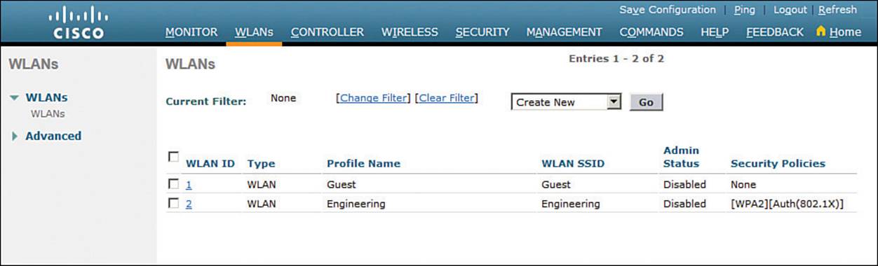
Figure 15-15 Displaying WLANs Configured on a Controller
Be aware that by default, a controller will not allow management traffic that is initiated from a WLAN. That means you (or anybody else) cannot access the controller GUI or CLI from a wireless device that is associated to the WLAN. This is considered to be a good security practice because the controller is kept isolated from networks that might be easily accessible or where someone might eavesdrop on the management session traffic. Instead, you can access the controller through its wired interfaces.
You can change the default behavior on a global basis (all WLANs) by selecting Management > Mgmt Via Wireless, as shown in Figure 15-16. Check the box to allow management sessions from any WLAN that is configured on the controller.
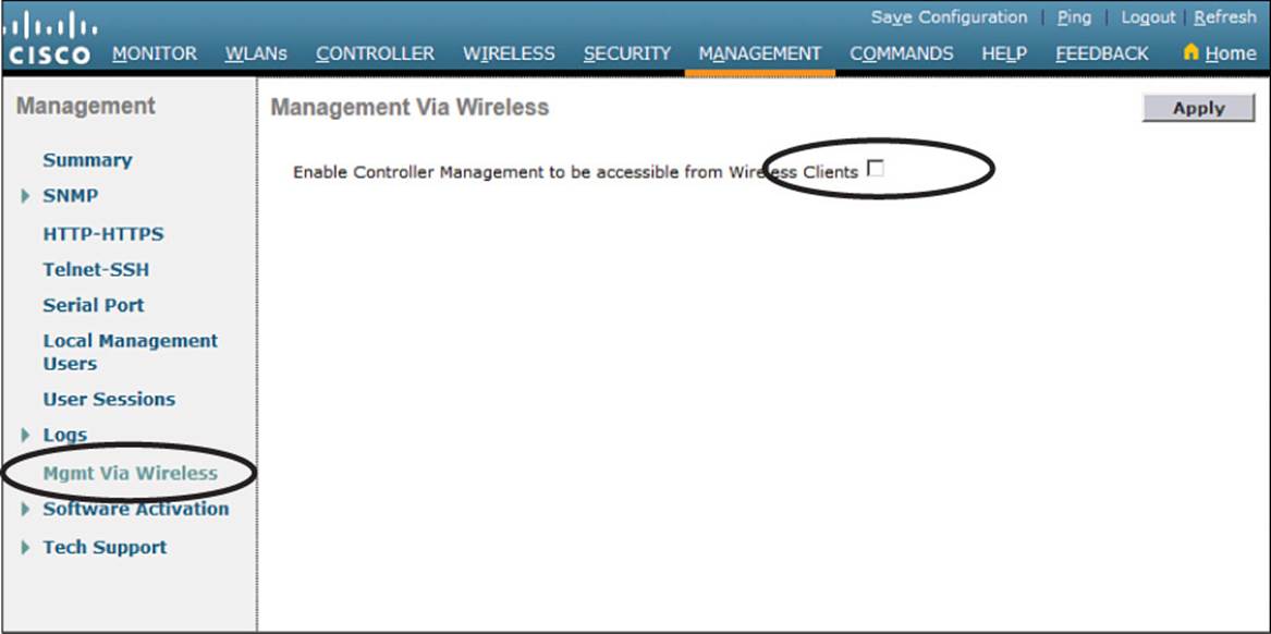
Figure 15-16 Configuring Management Access from Wireless Networks
Exam Preparation Tasks
As mentioned in the section, “How to Use This Book,” in the Introduction, you have a couple of choices for exam preparation: the exercises here, Chapter 21, “Final Review,” and the exam simulation questions on the DVD.
Review All Key Topics
Review the most important topics in this chapter, noted with the Key Topic icon in the outer margin of the page. Table 15-3 lists a reference of these key topics and the page numbers on which each is found.
![]()
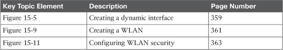
Table 15-3 Key Topics for Chapter 15
All materials on the site are licensed Creative Commons Attribution-Sharealike 3.0 Unported CC BY-SA 3.0 & GNU Free Documentation License (GFDL)
If you are the copyright holder of any material contained on our site and intend to remove it, please contact our site administrator for approval.
© 2016-2026 All site design rights belong to S.Y.A.