CCNA Wireless 200-355 Official Cert Guide (2016)
Chapter 2. RF Standards
This chapter covers the following topics:
![]() Regulatory Bodies—This section describes the organizations that regulate radio frequency spectrum and its uses.
Regulatory Bodies—This section describes the organizations that regulate radio frequency spectrum and its uses.
![]() IEEE Standards Body—This section discusses the IEEE and the 802.11 standards that define wireless LAN operation.
IEEE Standards Body—This section discusses the IEEE and the 802.11 standards that define wireless LAN operation.
![]() 802.11 Channel Use—This section covers each of the frequency bands used for 802.11 wireless LANs and the encoding and modulation methods that are used in wireless LANs.
802.11 Channel Use—This section covers each of the frequency bands used for 802.11 wireless LANs and the encoding and modulation methods that are used in wireless LANs.
![]() IEEE 802.11 Standards—This section describes the standards that define the progressive generations of 802.11 wireless LANs.
IEEE 802.11 Standards—This section describes the standards that define the progressive generations of 802.11 wireless LANs.
![]() Wi-Fi Alliance—This section introduces the global industry association that promotes and certifies wireless LAN products to ensure interoperability.
Wi-Fi Alliance—This section introduces the global industry association that promotes and certifies wireless LAN products to ensure interoperability.
This chapter covers the following exam topics:
![]() 2.1—Describe basic Wi-Fi governance
2.1—Describe basic Wi-Fi governance
![]() 2.1a—Describe regional regulatory bodies
2.1a—Describe regional regulatory bodies
![]() 2.1b—IEEE 802.11
2.1b—IEEE 802.11
![]() 2.1c—Wi-Fi Alliance
2.1c—Wi-Fi Alliance
![]() 2.2—Describe usable channel and power combination
2.2—Describe usable channel and power combination
![]() 2.2a—Regional EIRP limitation examples
2.2a—Regional EIRP limitation examples
![]() 2.2b—ISM, UNII frequency bands
2.2b—ISM, UNII frequency bands
![]() 2.3—Describe 802.11 fundamentals
2.3—Describe 802.11 fundamentals
![]() 2.3a—Modulation techniques
2.3a—Modulation techniques
![]() 2.3b—Channel width
2.3b—Channel width
![]() 2.3c—MIMO/MU-MIMO
2.3c—MIMO/MU-MIMO
![]() 2.3c(i)—MRC
2.3c(i)—MRC
![]() 2.3c(ii)—Beam forming
2.3c(ii)—Beam forming
![]() 2.3c(iii)—Spatial streams
2.3c(iii)—Spatial streams
To communicate successfully, wireless devices must first find each other in the radio frequency (RF) spectrum and then use compatible methods to generate RF signals, modulate and encode data, negotiate communication parameters and features, and so on—all without interfering with the operation of other wireless devices. This chapter covers the agencies that regulate, standardize, and validate the correct use of wireless LAN devices.
“Do I Know This Already?” Quiz
The “Do I Know This Already?” quiz allows you to assess whether you should read this entire chapter thoroughly or jump to the “Exam Preparation Tasks” section. If you are in doubt about your answers to these questions or your own assessment of your knowledge of the topics, read the entire chapter. Table 2-1 lists the major headings in this chapter and their corresponding “Do I Know This Already?” quiz questions. You can find the answers in Appendix A, “Answers to the ‘Do I Know This Already?’ Quizzes.”
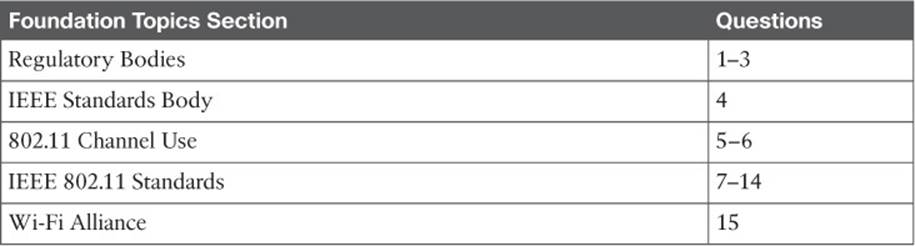
Table 2-1 “Do I Know This Already?” Section-to-Question Mapping
Caution
The goal of self-assessment is to gauge your mastery of the topics in this chapter. If you do not know the answer to a question or are only partially sure of the answer, you should mark that question as wrong for purposes of the self-assessment. Giving yourself credit for an answer you correctly guess skews your self-assessment results and might provide you with a false sense of security.
1. Which regulatory body allocated the 2.4–2.5-GHz band for industrial, scientific, and medical use?
a. IEEE
b. ETSI
c. ITU-R
d. FCC
2. The U-NII-1 band is used for which one of the following purposes?
a. 2.4-GHz wireless LANs
b. 5-GHz wireless LANs
c. Medical applications
d. Point-to-point links
3. In the 2.4-GHz band, the FCC limits the EIRP of a point-to-multipoint link to which one of the following maximum values?
a. 100 mW
b. 20 dBm
c. 50 mW
d. 36 dBm
4. Wireless LAN operation is defined in which one of the following standards?
a. 802.1
b. 802.2
c. 802.3
d. 802.11
e. 802.15
5. Which one of the following specifies the correct list of non-overlapping channels for DSSS use in the 2.4-GHz band?
a. 1, 2, 3
b. 1, 5, 10
c. 1, 6, 11
d. 1, 8, 13
e. All of channels 1–14
6. The U-NII-1 band begins at which one of the following channel numbers?
a. 0
b. 1
c. 24
d. 36
7. Which of the following standards apply to wireless LAN operation in the 5-GHz band? (Choose all that apply.)
a. IEEE 802.1
b. IEEE 802.11g
c. IEEE 802.11a
d. IEEE 802.11n
e. IEEE 802.11ac
f. IEEE 802.11b
g. IEEE 802.11-2012
8. Which of the following wireless LAN standards use OFDM for transmissions? (Choose all that apply.)
a. 802.11-1997
b. 802.11b
c. 802.11g
d. 802.11a
9. Which one of the following correctly specifies the maximum theoretical data rate of the 802.11b, 802.11a, and 802.11n standards, respectively?
a. 11 Mbps, 54 Mbps, 600 Mbps
b. 54 Mbps, 54 Mbps, 150 Mbps
c. 1 Mbps, 11 Mbps, 54 Mbps
d. 11 Mbps, 20 Mbps, 40 Mbps
10. A 2×3 MIMO device correctly describes which one of the following?
a. A device with two radios and three antennas
b. A device with two transmitters and three receivers
c. A device with two bonded channels and three spatial streams
d. A device with two receivers and three transmitters
11. An 802.11n device can aggregate channels to which one of the following maximum widths?
a. 5 MHz
b. 20 MHz
c. 40 MHz
d. 80 MHz
12. Which one of the following standards can make use of multiple spatial streams on a transmitter and a receiver? (Choose all that apply.)
a. 802.11n
b. 802.11b
c. 802.11g
d. 802.11a
e. 802.11ac
f. All of these answers are correct.
13. Which one of the following is the highest or best modulation scheme that can be used with 802.11ac devices?
a. QPSK 3/4
b. 256-QAM
c. 128-QAM
d. 64-QAM
e. 16-QAM
14. What is the maximum number of spatial streams supported by 802.11ac?
a. 1
b. 2
c. 4
d. 8
e. 16
15. Which one of the following organizations certifies 802.11 interoperability?
a. ITU-R
b. FCC
c. IEEE
d. Wi-Fi Alliance
e. Cisco
Foundation Topics
Regulatory Bodies
The entire frequency spectrum is composed of all possible frequencies, from very low up to cosmic rays. The part of the spectrum that is usable for radio communication, the radio frequency (RF) portion, ranges from about 3 kHz to 300 GHz. Frequencies within the RF spectrum are available because they exist everywhere, but it would not be wise to use any frequency at will. For example, suppose someone decides to set up a radio transmitter to broadcast a signal on 123.45 MHz. Unless other people know about the transmitter’s frequency and have radio receivers that can tune to that frequency, no one will be able to receive the signal. Even further, a frequency might be used by one entity for a specific purpose, while another entity might try to use the same frequency for a different purpose. To keep the RF spectrum organized and open for fair use, regulatory bodies were formed.
ITU-R
A telecommunications regulatory body regulates or decides which part of the RF spectrum can be used for a particular purpose, in addition to how it can be used. A country might have its own regulatory body that controls RF spectrum use within its borders, but RF signals can be more far-reaching than that. For example, one purpose for shortwave radio stations is to broadcast from one country around the earth to reach other countries. In a similar manner, one radio manufacturer might sell its equipment internationally, where a transmitter or receiver might be used in any global location.
To provide a hierarchy to manage the RF spectrum globally, the United Nations set up the International Telecommunication Union Radiocommunication Sector (ITU-R; http://www.itu.int). The ITU-R maintains spectrum and frequency assignments in three distinct regions:
![]() Region 1: Europe, Africa, and Northern Asia
Region 1: Europe, Africa, and Northern Asia
![]() Region 2: North and South America
Region 2: North and South America
![]() Region 3: Southern Asia and Australasia
Region 3: Southern Asia and Australasia
While the ITU-R strives to make the RF spectrum usable by all countries, it also tries to make sure that the RF signals from one country do not interfere with the signals of another country. It also attempts to determine the expected usages of each segment of the spectrum. The ITU-R even keeps track of geostationary satellite orbits and frequencies so that signals for one country’s satellites do not harmfully interfere with those of another country.
Most bands in the RF spectrum are tightly regulated, requiring you to apply for a license from a regulatory body before using a specific frequency. The regulatory bodies typically determine the allowed type of emission and set limits on things like the emission source and power. Licensed bands might seem restrictive, for a good reason: “Harmful” or disruptive interference is kept to a minimum because frequencies are reserved for approved transmitters, purposes, and locations. To use a frequency in a licensed band, someone has to submit an application to a regulatory body that governs frequency use in a given country, wait for approval, and then abide by any restrictions that are imposed.
In contrast, the ITU-R allocated the following two frequency ranges specifically for industrial, scientific, and medical (ISM) applications. Although there are other ISM bands, too, there are mainly two that apply to wireless LANs:
![]()
2.400 to 2.500 GHz
5.725 to 5.825 GHz
The purposes for these bands are broad and access is open to anyone who wants to use them. In other words, the ISM bands are unlicensed and no registration or approval is needed to transmit on one of the frequencies.
While unlicensed bands are more accessible and convenient to use, they are much more vulnerable to interference and misuse. For example, suppose that you decide to set up a transmitter in your office to use one frequency. The next day, someone in a neighboring office sets up his own transmitter to broadcast on the same or an overlapping frequency. Because the band is unlicensed, you can do little to relieve the interference other than move your transmitter to a different frequency or use diplomacy to convince your neighbor to move his transmitter instead.
Fortunately, all the frequency bands used for wireless LANs are unlicensed. You can purchase a wireless LAN device and begin to use it immediately—provided you abide by the rules set up by the regulatory agency that governs RF use in your country. Usually, unlicensed transmitters must stay within an approved frequency range and transmit within an approved maximum power level. Several national regulatory agencies are discussed in the following sections.
FCC
In the United States, the Federal Communications Commission (FCC; http://www.fcc.gov) regulates RF frequencies, channels, and transmission power. Some other countries choose to follow the FCC rules, too. In addition to the 2.4–2.5-GHz ISM band allocated by the ITU-R, the FCC has allocated the Unlicensed National Information Infrastructure (U-NII) frequency space in the 5-GHz band for wireless LAN use. U-NII is actually four separate sub-bands, as follows:
![]()
U-NII-1 (Band 1): 5.15 to 5.25 GHz
U-NII-2 (Band 2): 5.25 to 5.35 GHz
U-NII-2 Extended (Band 3): 5.47 to 5.725 GHz
U-NII-3 (Band 4): 5.725 to 5.825 GHz (also allocated as ISM)
Tip
As you read and work with the 5-GHz bands, be aware that you may see various forms of the band names. For example, the 5.15–5.25-GHz band is often referenced by names like U-NII-1, UNII-1, U-NII Low, and so on.
All transmitting equipment must be approved by the FCC before it can be sold to users. For the 2.4- and 5-GHz unlicensed bands, the FCC requires strict limits on the effective isotropic radiated power (EIRP). Recall from Chapter 1, “RF Signals and Modulation,” that the EIRP is the net power level that is being transmitted from an antenna that is connected to a transmitter.
You must be aware of the EIRP limits and make sure that your wireless LAN equipment does not exceed the limits. If the FCC has to approve wireless transmitters, it might seem logical that the maximum EIRP of the equipment would have to be approved, too. Why would you, as a wireless user, have to worry about staying within the limits? Some transmitters are sold without antennas, so you are free to buy and install your own. Without considering the EIRP limit, you might choose an antenna that has too much gain, which would raise the EIRP too high.
In an effort to prevent users from exceeding the EIRP limits, the FCC requires all removable antennas to have a unique, nonstandard connector, based on the transmitter manufacturer. The original idea was to require both transmitter and antenna to be purchased from the same manufacturer, preventing the end user from mixing and matching parts from different vendors.
Cisco uses a variant of the threaded Neill-Concelman (TNC) connector on its equipment. The reverse polarity TNC (RP-TNC) connector is identical to the TNC, but has key male and female parts reversed so that antennas with TNC connectors cannot be connected. Figure 2-1 shows the male version of the regular TNC and RP-TNC connector side by side.
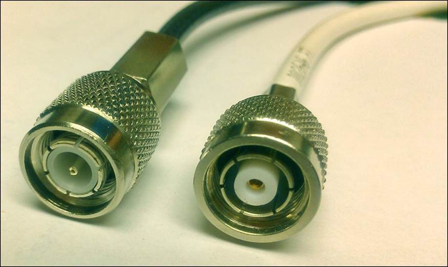
Figure 2-1 Comparison Between TNC (left) and Cisco RP-TNC Connector (right)
In practice, you can find all sorts of antennas from a wide variety of manufacturers that all have RP-TNC connectors. In other words, you cannot depend on the FCC and the RP-TNC connector to limit the EIRP of your wireless equipment; you have to do that yourself.
Transmitters in the 2.4-GHz band can be used indoors or outdoors. The power emitted at the transmitter must be limited to 30 dBm and the EIRP limited to 36 dBm. An antenna gain of +6 dBi is assumed. However, there is some flexibility according to the following two rules, based on the intended spread of the signal:
![]()
![]() Point-to-multipoint links—Where the transmitted signal propagates in all directions, you can make adjustments according to a 1:1 rule. For each dBm you remove from the transmitter, one dBi can be added to the antenna gain, as long as the EIRP is no greater than 36 dBm.
Point-to-multipoint links—Where the transmitted signal propagates in all directions, you can make adjustments according to a 1:1 rule. For each dBm you remove from the transmitter, one dBi can be added to the antenna gain, as long as the EIRP is no greater than 36 dBm.
![]() Point-to-point links—Where the transmitted signal propagates in one general direction, you can make adjustments according to a 3:1 rule. For each dBm you remove from the transmitter, 3 dBi can be added to the antenna gain. The resulting EIRP can exceed 36 dBm but cannot be greater than 56 dBm.
Point-to-point links—Where the transmitted signal propagates in one general direction, you can make adjustments according to a 3:1 rule. For each dBm you remove from the transmitter, 3 dBi can be added to the antenna gain. The resulting EIRP can exceed 36 dBm but cannot be greater than 56 dBm.
Transmitters in the 5-GHz bands must follow the FCC limits listed in Table 2-2. In each of the U-NII bands, you can make power adjustments according to the 1:1 rule. Notice that the U-NII-1 band is the only one restricted to indoor use.
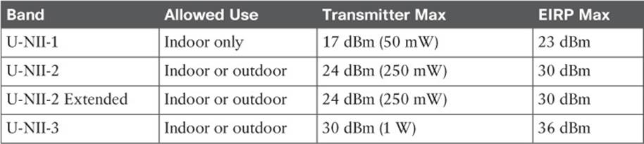
Table 2-2 FCC Requirements in the 5-GHz U-NII Bands
Normally, transmitters operating in any of the 2.4- and 5-GHz unlicensed bands must endure any interference caused by other transmitters. The FCC requires one exception in the U-NII-2 and U-NII-2 Extended bands: When a signal from an approved device, such as a military or weather radar, is detected on a frequency, all other transmitters must move out of the way to a different frequency. This is known as dynamic frequency selection (DFS).
ETSI
In Europe and several other countries, the European Telecommunication Standards Institute (ETSI; http://www.etsi.org) regulates radio transmitter use. Like the FCC, the ETSI allows wireless LANs to be used in the 2.4-GHz ISM and most of the same 5-GHz U-NII bands; however, the U-NII-3 band is a licensed band and cannot be used.
Table 2-3 lists the transmitter requirements for each of the bands. The ETSI allows adjustments to the transmit power and antenna gain, as long as the maximum EIRP is not exceeded.
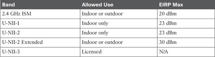
Table 2-3 ETSI Requirements in the 2.4- and 5-GHz Bands
The ETSI regulations also include DFS, which requires wireless LAN transmitters to move to a random frequency after a radar signal is detected.
Other Regulatory Bodies
Wireless LAN equipment use is regulated outside the Americas and Europe, too. Does each country have its own set of regulations? Not necessarily; a country might have its own or it can adhere to all or parts of the regulations of a larger, more established regulatory body. Countries that use a common set of RF regulations are known as a regulatory domain.
For example, a Cisco wireless device that is compatible with the American regulatory domain can also be used in Canada, many Latin and South American countries, and in the Philippines.
Cisco manufactures wireless devices for use in at least 13 different regulatory domains. The basic wireless LAN operation is identical in all domains, but the frequency ranges, channels, and maximum transmit powers can differ.
IEEE Standards Body
To pass data over a wireless link, many parameters have to be defined and standardized. Wireless LANs rarely involve just one transmitter and receiver; normally, many devices must contend for use of airtime on a frequency. The Institute of Electric and Electronic Engineers (IEEE;http://ieee.org) maintains the industry standards that are used for wireless LANs, among many others.
The IEEE is a professional organization made up of engineers from around the world. It is organized as a collection of “societies” that are focused on particular engineering areas. For example, the IEEE Computer Society develops and maintains standards on a variety of topics related to computing, including Ethernet and wireless LANs.
The IEEE 802 standards all deal with local-area networks and metropolitan-area networks (LANs and MANs, respectively). The standards mainly deal with the physical and data link layers of the OSI model, and with transporting variable-size data packets across a network media. As you explore the portion of the 802 standards that are dedicated to wireless LANs, you will find that they focus on accessing the shared RF media (physical layer or Layer 1) and on sending and receiving data frames (data link layer or Layer 2).
Tip
What is the significance of the number 802? The Local Network Standards Committee of the IEEE Computer Society first met in February 1980, to begin work on “Project 802,” the first LAN standard. The number 802 was the next sequential project number, but also fit the odd coincidence of the date—year 80, second month.
To develop networking standards, the IEEE is organized into working groups, which have an open membership. Each working group is assigned an index number that is appended to the 802 standards family number. For example, 802.1 refers to the first working group, which developed standards for network bridging. Table 2-4 lists a few familiar 802 working groups. Notice that the eleventh working group, 802.11, is responsible for the wireless LAN standards that are used by Cisco, many other wireless vendors, and users like yourself. For the remainder of this chapter, the focus will be on 802.11.
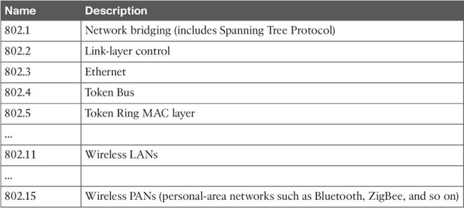
Table 2-4 Example IEEE 802 Working Groups
As a new improvement is needed or the technology advances, a study group (SG) researches the topic to see whether an amendment to the 802.11 standard is needed. Each time a new amendment is necessary, a new task group (TG) is formed to collaborate and develop it. Task groups are assigned a suffix letter in alphabetic order. For example, as amendments are introduced, their names become 802.11a, 802.11b, 802.11c, and so on. If there are enough amendments to reach letter z, any subsequent amendments are given a two-letter suffix, beginning with the letter a followed by letters a through z. At the time of this writing, the 802.11 working group had assigned amendments 802.11aa through 802.11ay.
Once a draft amendment is completed, it must be voted on and ratified. At that point, manufacturers can then begin to build products that operate according to all or a part of the standard. For example, when the 802.11n amendment was finalized and published, the new features of 802.11n were then added to many wireless LAN devices.
Sometimes an amendment takes a very long time to get through the development, voting, and final approval processes, so many manufacturers will decide to move ahead and implement the draft amendment into their products early. Usually a manufacturer has to decide whether the draft amendment is stable enough to implement into device hardware or is likely to receive drastic changes before it is ratified. This scenario occurred with the 802.11n amendment. Many manufacturers offered early implementations as “Draft N-compliant” products, which may or may not have been compatible with similar products from other manufacturers.
The 802.11 standards usually have the year they were ratified added to their names. For example, the original 802.11 standard was issued in 1997, so it is now known as 802.11-1997. Likewise, the name 802.11a-1999 means that the 802.11a amendment was ratified in 1999.
Periodically, the IEEE 802 working group chooses to revise the 802.11 standard as a whole. When this occurs, every amendment that has been ratified since the last 802.11 revision is “rolled up” and absorbed into the new updated standard. The idea is to maintain one document that defines the entire standard, as of a certain date, so that wireless developers can find all of the technical details in one place.
Even though the amendments become part of the larger standard, their names are still commonly used to reference the specific functions they introduced. Since its introduction in 1997, the 802.11 standard has been revised in 1999, 2007, and 2012. The current 802.11-2012 standard is more than 2700 pages long, and the 2016 revision is projected to be at least 3700 pages!
802.11 Channel Use
Chapter 1 introduced RF frequency, bands, and channels in a generic fashion. Wireless devices built around the 802.11 standard must also have a standardized concept of the same RF parameters. As wireless devices move around, they should be able to detect and participate in wireless LANs as they become available, regardless of geographic location.
The following sections describe the 802.11 channel definitions in the 2.4- and 5-GHz bands.
Channels in the 2.4-GHz ISM Band
In the 2.4-GHz ISM band, the frequency space is divided up into 14 channels, numbered 1 through 14. With the exception of channel 14, the channels are spaced 5 MHz apart, as listed in Table 2-5.
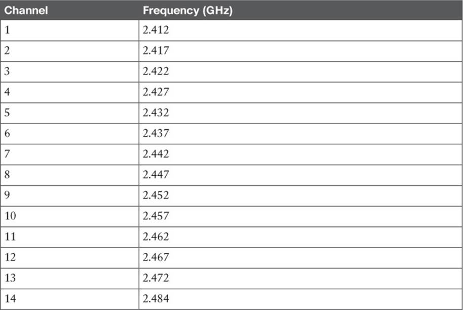
Table 2-5 IEEE 802.11 Channel Layout in the 2.4-GHz Band
The 802.11 standard allows either direct-sequence spread spectrum (DSSS) or orthogonal frequency-division multiplexing (OFDM) modulation and coding schemes to be used in the 2.4-GHz band. DSSS radios require each channel to be 22 MHz wide, and OFDM requires 20 MHz. Either way, with only 5 MHz between channels, transmissions on neighboring channels are bound to overlap and interfere with each other. (This condition is covered in Chapter 3, “RF Signals in the Real World.”)
Even though the band is made up of 14 channels, not all of them may be used in all countries. For example, the FCC limits the band to channels 1 through 11 only. The ETSI permits channels 1 through 13. Japan permits all 14 channels to be used, but channel 14 has some restrictions.
Figure 2-2 shows how 802.11 signals can overlap on neighboring 2.4-GHz channels. The only way to prevent transmitters on nearby channels from interfering with each other is to keep them on channels that are spaced farther apart. The most common arrangement is to use only channels 1, 6, and 11, which do not overlap with each other at all.
![]()
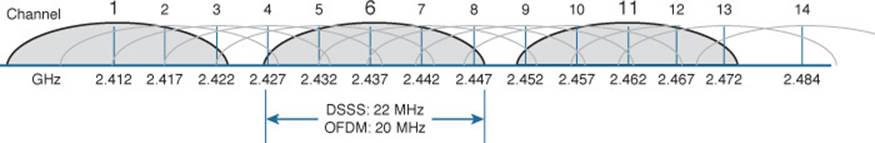
Figure 2-2 Channel Layout in the 2.4-GHz Band
Tip
One scheme uses channels 1, 5, 9, and 13 to gain an extra channel, but it is not commonly used. With DSSS, the channels end up overlapping, which violates the 802.11 definition for adjacent channels and also raises the noise floor. Only the OFDM 20-MHz-wide channels can avoid overlapping each other. Channel 13 presents an interesting case because it is not supported on all wireless clients in all areas of the world.
Why should you be concerned about non-overlapping channels? After all, having three non-overlapping channels might seem like plenty. Problems can arise when you need to set up several wireless LAN transmitters in the same general area. You could set the first three transmitters to each use a different channel, but the fourth or fifth ones would have to reuse one of the three non-overlapping channels.
Reusing channels becomes a puzzle that you have to solve when you administer a growing wireless LAN. Chapter 7, “Planning Coverage with Wireless APs,” covers channel reuse in greater detail. Be aware that the three-channel limitation also applies to every transmitter located in an area—regardless of whether you administer them. Because the 2.4-GHz band is unlicensed, anyone is free to bring up a transmitter on any of the three non-overlapping channels without consulting you or anybody else. In fact, they might decide to set their transmitter to use any of the 14 available channels, thinking that none of them overlap.
Channels in the 5-GHz U-NII Bands
Recall that the 5-GHz band is organized as four separate, smaller bands: U-NII-1, U-NII-2, U-NII-2 Extended, and U-NII-3. The bands are all divided into channels that are 20 MHz apart, as listed in Table 2-6.
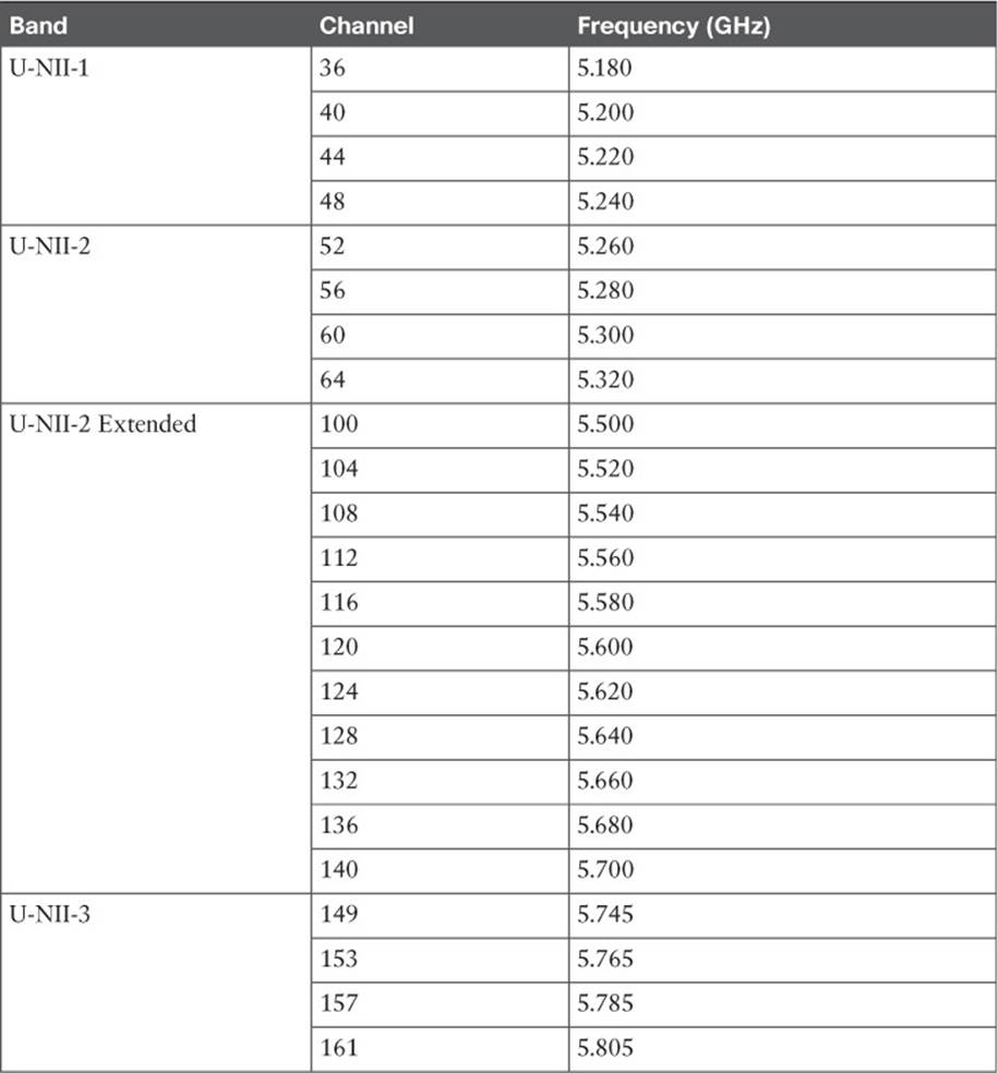
Table 2-6 IEEE 802.11 Channel Layout in the 5-GHz Bands
The fact that the 5-GHz space is divided into four different bands might seem confusing. Even worse is the channel numbering. For instance, why is the first channel in the U-NII-1 band called channel 36 instead of channel 1? And why are neighboring channels actually four channel numbers apart?
The answers lie in the 802.11 standard itself: The entire 5-GHz frequency space is defined as a sequence of channels spaced 5 MHz apart, beginning with channel 0 at 5.000 GHz. Therefore, the first U-NII-1 channel is located at 5.180 GHz, which corresponds to channel number 36. Each U-NII channel is 20 MHz wide, so an adjacent channel is located four 5-MHz channel widths, or four channel numbers, away.
The FCC originally allocated three separate bands as U-NII-1, U-NII-2, and U-NII-3, each having four 20-MHz channels. In 2004, the FCC added the U-NII-2 Extended band, which offered 11 additional 20-MHz channels. Figure 2-3 shows the complete frequency layout of the four bands. Notice that the U-NII-1 and U-NII-2 bands are contiguous, but that the U-NII-2 Extended and U-NII-3 bands are separated by a range of frequencies that are unusable at the time of this writing but that might become available in the future.
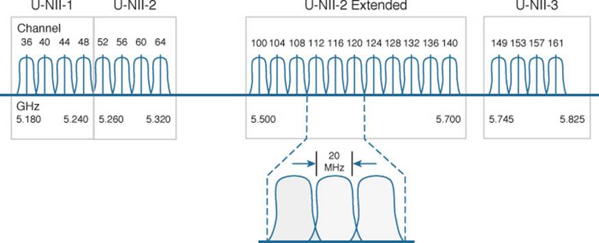
Figure 2-3 Channel Layout in the 5-GHz U-NII Bands
Tip
The U-NII-1, -2, and -3 bands each have four channels. Sometimes you may find 802.11 devices that support a fifth channel in the U-NII-3 band as channel 165.
The 802.11 standard allows only OFDM modulation and coding schemes to be used in the U-NII bands. OFDM requires a 20-MHz channel width, which fits perfectly with the 20-MHz spacing in the U-NII bands. In other words, neighboring channels can be used in the same area without overlap or interference.
With all four U-NII bands set aside for wireless LANs, a total of 23 non-overlapping channels are available. This is quite a contrast to the three non-overlapping channels in the 2.4-GHz band. Having 23 channels at your disposal gives you much more flexibility in a crowded environment. The additional channels can also be leveraged to scale wireless LAN performance, as explained in the 802.11n and 802.11ac sections later in this chapter.
IEEE 802.11 Standards
The 802.11 standard defines the mechanisms that devices can use to communicate wirelessly with each other. Through 802.11, RF signals, modulation, coding, bands, channels, and data rates all come together to provide a robust communication medium.
Since the original IEEE 802.11 standard was published in 1997, there have been many amendments added to it. The amendments cover almost every conceivable aspect of wireless LAN communication, including things like quality of service (QoS), security, RF measurements, wireless management, more efficient mobility, and ever-increasing throughput.
By now, most of the amendments have been rolled up into the overall 802.11 standard and no longer stand alone. Even so, the amendments may live on and be recognized in the industry by their original task group names. For example, the 802.11b amendment was approved in 1999, was rolled up into 802.11 in 2007, but is still recognized by its name today. When you shop for wireless LAN devices, you will often find the 802.11a, b, g, and n amendments listed in the specifications.
The following sections discuss the progression of 802.11 amendments that have allowed wireless LANs to steadily increase in performance over time. The original amendment names are used to distinguish each one. At the CCNA level, you should become familiar with these amendments. As you read through the remainder of this chapter, notice how the transmission types, modulation types, and data rates presented in Chapter 1 fit into the 802.11 standard.
802.11-1997
The original 802.11 standard was ratified in 1997. It included two main transmission types that were available at the time: FHSS and DSSS, for use only in the 2.4-GHz band. The theoretical data rates included 1 and 2 Mbps, as listed in Table 2-7.
![]()
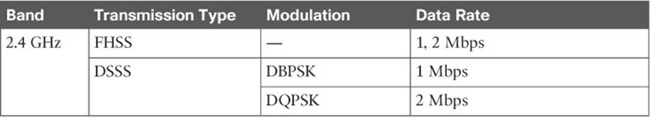
Table 2-7 IEEE 802.11-1997 Data Rates
802.11b
To increase throughput over the original 802.11-1997 standard, 802.11b was introduced in 1999. It offered data rates of 5.5 and 11 Mbps through the use of Complementary Code Keying (CCK). Because 802.11b was based on DSSS and was used in the 2.4-GHz band, it was backward compatible with the original standard. Devices could select either 1, 2, 5.5, or 11 Mbps by simply changing the modulation and coding schemes. Table 2-8 lists the new data rates introduced in 802.11b.
![]()
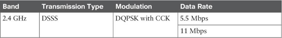
Table 2-8 IEEE 802.11b Data Rates
802.11g
With 802.11b, the DSSS maximum data rate was limited to 11 Mbps. To increase data rates further, a different transmission type was needed. The 802.11g amendment was based on OFDM and was introduced in 2003. It is commonly called Extended Rate PHY (ERP) or ERP-OFDM. Whenever you see ERP, think of 802.11g in the 2.4-GHz band. Table 2-9 lists the data rates available with 802.11g.
![]()
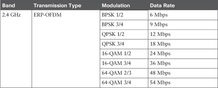
Table 2-9 IEEE 802.11g Data Rates
By selecting one of eight different modulation schemes, wireless devices can choose data rates of 6, 9, 12, 18, 24, 36, 48, or 54 Mbps. The higher data rates can be used when the signal strength and signal-to-noise ratio (SNR) are optimal.
Clearly, 802.11g offers far superior throughput than 802.11b. It might seem logical to simply use 802.11g and its higher data rates everywhere. Sometimes that is not possible because 802.11b-only devices are still being used on a wireless LAN. Notice that 802.11g and 802.11b use completely different transmission types—OFDM versus DSSS. This means that 802.11g and 802.11b devices cannot communicate directly because they cannot understand each other’s RF signals.
Oddly enough, 802.11g was designed to be backward compatible with legacy 802.11b devices. Devices using 802.11g and OFDM are able to downgrade and understand 802.11b DSSS messages. However, the reverse is not true; 802.11b devices are limited to DSSS, so they are not able to understand any OFDM data. When two 802.11g devices are communicating with OFDM, 802.11b devices cannot understand any of the transmissions, so they might interrupt with transmissions of their own.
To allow both OFDM and DSSS devices to coexist on a wireless LAN, 802.11g offers a protection mechanism. The idea is to precede each 802.11g OFDM transmission with DSSS flags that 802.11b devices can understand. Figure 2-4 compares the basic sequence of events as data is transmitted in a native 802.11g OFDM network and when the 802.11g protection mechanism is enabled. When an 802.11g device is ready to transmit data in protection mode, it first sends a Request to Send (RTS) and a Clear to Send (CTS) message using DSSS (and a low data rate) that informs all 802.11b devices that an OFDM transmission will follow. Any 802.11b devices that are listening must wait a predefined time until the transmission is complete because the OFDM transmission is unintelligible.
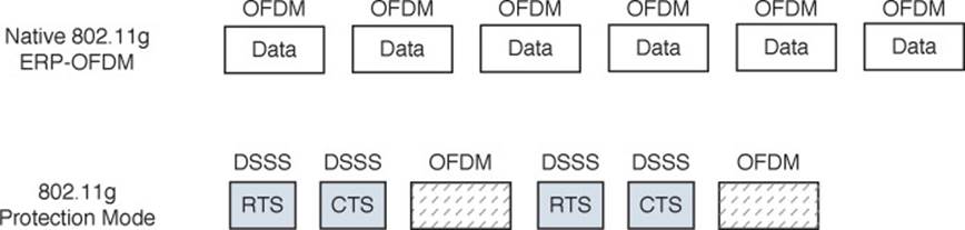
Figure 2-4 Comparison of 802.11g Native and Protected Mode Transmissions
Protection mode is enforced if an 802.11b device is detected on a wireless LAN. If the 802.11b device leaves the local network, protection mode is lifted. While the protection mechanism enables 802.11b and 802.11g devices to share the wireless medium, it also reduces throughput significantly—often by one half or more. To get the most performance out of an 802.11g network, you should make sure that there are no 802.11b-only devices in use.
Be aware that 802.11g has the following limitations:
![]() It is used in the 2.4-GHz band, which offers only three non-overlapping channels.
It is used in the 2.4-GHz band, which offers only three non-overlapping channels.
![]() OFDM devices are limited to a maximum transmit power of 15 dBm, rather than the 20 dBm limit for DSSS. This is due to the way the RF energy is spread across the channel width.
OFDM devices are limited to a maximum transmit power of 15 dBm, rather than the 20 dBm limit for DSSS. This is due to the way the RF energy is spread across the channel width.
802.11a
Both 802.11b and 802.11g share one problem: They live in the 2.4-GHz ISM band. Having only three non-overlapping channels can limit wireless LAN growth in an area—assuming that all 802.11 devices stay within those three channels and do not cause unnecessary interference. Even worse, the ISM band is not limited to 802.11 devices. A wide variety of transmitters—even microwave ovens—can use the 2.4-GHz band without any regard for channels at all.
With too few channels and the potential for interference, the 802.11a amendment was introduced to utilize the 5-GHz U-NII bands for wireless LANs. Only one of the four U-NII bands is designated as ISM, so the chance for non-802.11 interference is very low. In addition, many more channels are available for use.
The 802.11a amendment restricts devices to use OFDM only. The end result is a set of modulation schemes and data rates that are identical to those used for 802.11g, but with less chance for interference and more room for growth. Table 2-10 lists the data rates available with 802.11a.
![]()
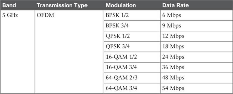
Table 2-10 IEEE 802.11a Data Rates
802.11a was not designed to be backward compatible with anything else, so there is no need to support data rates below 6 Mbps or to support DSSS at all. Wireless devices can select one of the eight modulation schemes to support data rates of 6, 9, 12, 18, 24, 36, 48, or 54 Mbps.
802.11a is based on OFDM channels that are 20 MHz wide. Even though the U-NII bands have channels that are spaced 20 MHz apart (a perfect fit), signals on adjacent channels might still have a small amount of overlap. Therefore, 802.11a recommends that transmitters in the same geographic space stay separated by one channel. In other words, one transmitter might use channel 36, but another should use channel 44 rather than the adjacent channel 40.
Tip
If the 802.11 amendment letters come in chronological order, how could the higher-performance 802.11a come before the lower-performance 802.11b? Actually, interference on the 2.4-GHz ISM band was so prevalent that a move to the 5-GHz bands was proposed right away. The 802.11a amendment was introduced in 1999—earlier in the same year as 802.11b. OFDM did come to the 2.4-GHz band, too, with 802.11g in 2003, mainly because migrating to 802.11a and 5 GHz required an investment in new hardware.
802.11n
Under the best conditions, both 802.11g and 802.11a are capable of offering a 54-Mbps data rate. Each amendment was introduced in the days when wired Ethernet devices used 10- or 100-Mbps connections. As the speed of Ethernet connections has progressed, 802.11 amendments have been introduced to keep in step.
The 802.11n amendment was published in 2009 in an effort to scale wireless LAN performance to a theoretical maximum of 600 Mbps. The amendment defines a number of techniques known as high throughput (HT) that can be applied to either the 2.4- or 5-GHz band. 802.11n was designed to be backward compatible with OFDM used in 802.11g and 802.11a.
Before 802.11n, wireless devices used a single transmitter and a single receiver. In other words, the components formed one radio, resulting in a single radio chain. This is also known as a single-in, single-out (SISO) system. The secret to 802.11n’s better performance is its use of multiple radio components, forming multiple radio chains. For example, an 802.11n device can have multiple antennas, multiple transmitters, and multiple receivers at its disposal. This is known as a multiple-input, multiple-output (MIMO) system.
802.11n devices are characterized according to the number of radio chains available. This is described in the form T×R, where T is the number of transmitters and R is the number of receivers. A 2×2 MIMO device has two transmitters and two receivers, and a 2×3 device has two transmitters and three receivers. The 802.11n amendment requires at least two radio chains (2×2), up to a maximum of four (4×4). Figure 2-5 compares the traditional 1×1 SISO device with 2×2 and 2×3 MIMO devices.
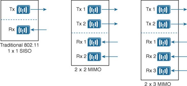
Figure 2-5 Example SISO and MIMO Devices
The multiple radio chains can be leveraged in a variety of ways. In fact, 802.11n has a rich set of features that can make many aspects of wireless communication more efficient. You should be familiar with the following features that improve throughput:
![]() Channel aggregation
Channel aggregation
![]() Spatial multiplexing (SM)
Spatial multiplexing (SM)
![]() MAC layer efficiency
MAC layer efficiency
You should also become familiar with the following features that improve the reliability of the 802.11n RF signals:
![]() Transmit beamforming (T×BF)
Transmit beamforming (T×BF)
![]() Maximal-ratio combining (MRC)
Maximal-ratio combining (MRC)
Each of these features is described in the sections that follow.
Channel Aggregation
Normally, an 802.11a or 802.11g wireless LAN device has one transmitter and one receiver that operate on one 20-MHz channel only. The transmitter and receiver can be configured or tuned to operate on different channels in a band, but only one channel at a time. Each 20-MHz OFDM channel has 48 subcarriers to carry data in parallel.
The 802.11n amendment increased the 20-MHz channel throughput by increasing the number of data subcarriers to 52. In addition, it introduced radios that could operate on either a single 20-MHz channel or a single 40-MHz channel. By doubling the channel width to 40 MHz, the throughput is also doubled.
Aggregated channels must always bond two adjacent 20-MHz channels. Figure 2-6 shows a comparison between two 20-MHz channels and one 40-MHz channel, formed from channels 36 and 40 in the 5-GHz band. Notice that the 20-MHz channels have a quiet space below and above, providing some separation between channels. When two 20-MHz channels are aggregated or bonded, the quiet space below and above remain, separating 40-MHz channels from each other. However, the quiet space that used to sit between the two 20-MHz channels can be used for additional subcarriers in the 40-MHz channel, for a total of 108. As more subcarriers are utilized, more data can be carried over time.
![]()
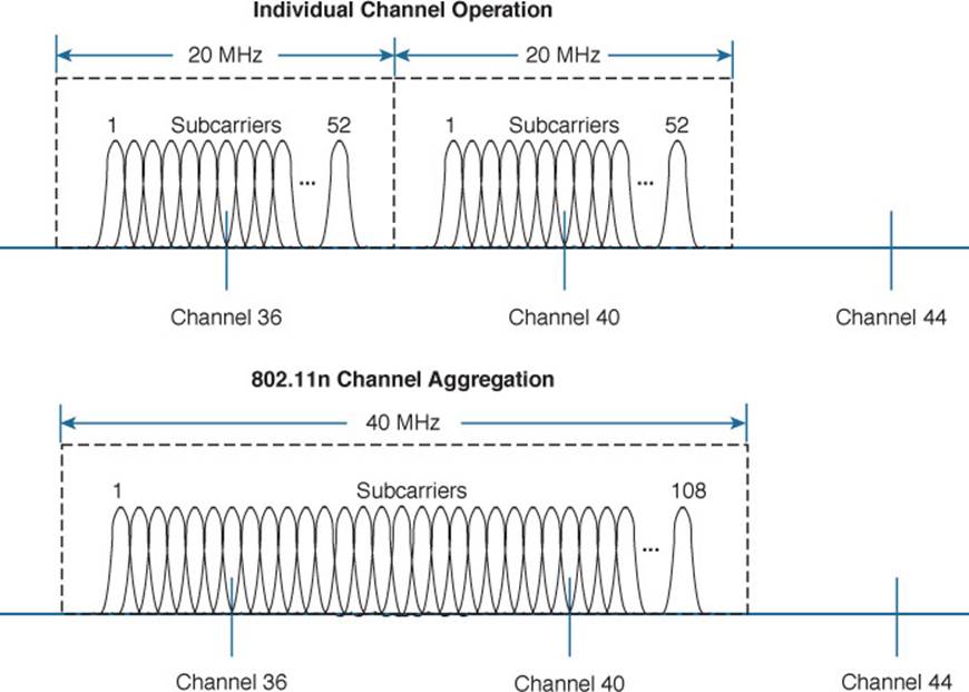
Figure 2-6 Comparing 20-MHz Channels to an 802.11n 4-MHz Channel
When channels are aggregated, the total number of available channels in a band decreases. For example, the 5-GHz band is made up of 23 non-overlapping 20-MHz channels. If aggregated 40-MHz channels are used instead, only 11 non-overlapping channels would be possible. That still gives plenty of channels to work with.
Now consider the 2.4-GHz band, which has only three non-overlapping channels. It just is not practical to try to aggregate any of them into 40-MHz channels. Therefore, channel aggregation is not recommended and not normally attempted on any 2.4-GHz channels.
Spatial Multiplexing
Channel aggregation can double the throughput by doubling the channel width—all with a single radio chain. An 802.11n device can have multiple radio chains waiting to be used. To increase data throughput even more, data can be multiplexed or distributed across two or more radio chains—all operating on the same channel, but separated through spatial diversity. This is known as spatial multiplexing.
How can several radios transmit on the same channel without interfering with each other? The key is to try to keep each signal isolated or easily distinguished from the others. Each radio chain has its own antenna; if each antenna is spaced some distance apart, the signals arriving at the receiver’s antennas (also appropriately spaced) will likely be out of phase with each other or at different amplitudes. This is especially true if the signals bounce off some objects along the way, making each antenna’s signal travel over a slightly different path to reach the receiver.
In addition, data can be distributed across the transmitter’s radio chains in a known fashion. In fact, several independent streams of data can be processed as spatial streams that are multiplexed over the radio chains. The receiver must be able to interpret the arriving signals and rebuild the original data streams by reversing the transmitter’s multiplexing function.
Spatial multiplexing requires a good deal of digital signal processing on both the transmitting and receiving end. This pays off by increasing the throughput over the channel—the more spatial streams that are available, the more data that can be sent over the channel.
![]()
The number of spatial streams that a device can support is usually designated by adding a colon and a number to the MIMO radio specification. For example, a 3×3:2 MIMO device would have three transmitters, three receivers, and would support two unique spatial streams. Figure 2-7shows spatial multiplexing between two 3×3:2 MIMO devices. A 3×3:3 device would be similar, but would support three spatial streams.
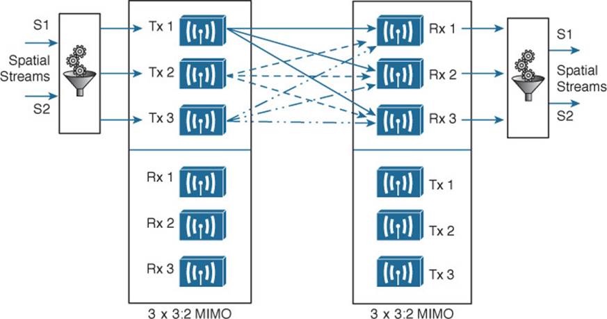
Figure 2-7 Spatial Multiplexing Between Two 3×3:2 MIMO Devices
Tip
Notice that a MIMO device can support a different number of unique spatial streams than it has transmitters or receivers. It might seem logical that each spatial stream is assigned to a transmitter/receiver, but that is not true. Spatial streams are processed so that they are distributed across multiple radio chains. The number of possible spatial streams depends on the processing capacity and the transmitter feature set of the 802.11n device—not on the number of its radios.
802.11n devices come with a variety of MIMO capabilities. Ideally, two devices should support an identical number of spatial streams to multiplex and demultiplex the data streams correctly. That is not always possible or even likely because more spatial streams usually translates to a greater cost. What happens when two devices have mismatched spatial stream support? They negotiate the wireless connection by informing each other of their capabilities. Then they can use the lowest number of spatial streams that they have in common, but a transmitting device can leverage an additional spatial stream to repeat some information for increased redundancy.
MAC Layer Efficiency
Even without multiple radio chains, 802.11n offers some important methods to make data communication more efficient. Two of the methods are as follows:
![]() Block acknowledgment—Normally, 802.11 requires that each frame of data transmitted must be acknowledged by the recipient. If a frame goes unacknowledged, the transmitter can assume that the frame was lost and needs to be resent. The overhead of having acknowledgment messages interleaved with every transmitted frame is inefficient; it uses up airtime on the shared media.
Block acknowledgment—Normally, 802.11 requires that each frame of data transmitted must be acknowledged by the recipient. If a frame goes unacknowledged, the transmitter can assume that the frame was lost and needs to be resent. The overhead of having acknowledgment messages interleaved with every transmitted frame is inefficient; it uses up airtime on the shared media.
With 802.11n, data frames can be transmitted in one burst. Only one acknowledgment is expected from the recipient after the burst is complete. More airtime can be spent sending data, increasing the overall throughput.
![]() Guard interval—As OFDM symbols are transmitted, they can take different paths to reach the receiver. If two symbols somehow arrive too close together, they can interfere with each other and corrupt the received data. This is known as intersymbol interference (ISI). The 802.11 standard requires a guard interval (GI), a period of 800 nanoseconds, between each OFDM symbol that is transmitted to protect against ISI.
Guard interval—As OFDM symbols are transmitted, they can take different paths to reach the receiver. If two symbols somehow arrive too close together, they can interfere with each other and corrupt the received data. This is known as intersymbol interference (ISI). The 802.11 standard requires a guard interval (GI), a period of 800 nanoseconds, between each OFDM symbol that is transmitted to protect against ISI.
As an option, you can configure 802.11n devices to use a much shorter 400-nanosecond guard interval. This allows OFDM symbols to be transmitted more often, increasing throughput by about 10 percent, at the expense of making data corruption more likely.
Transmit Beamforming
When a transmitter with a single radio chain sends an RF signal, any receivers that are present have an equal opportunity to receive and interpret the signal. In other words, the transmitter does nothing to prefer one receiver over another; each is at the mercy of its environment and surrounding conditions to receive at a decent SNR.
The 802.11n amendment offers a method to customize the transmitted signal to prefer one receiver over others. By leveraging MIMO, the same signal can be transmitted over multiple antennas to reach specific client locations more efficiently.
Usually multiple signals travel over slightly different paths to reach a receiver, so they can arrive delayed and out of phase with each other. This is normally destructive, resulting in a lower SNR and a corrupted signal. With transmit beamforming (T×BF), the phase of the signal is altered as it is fed into each transmitting antenna so that the resulting signals will all arrive in phase at a specific receiver. This has a constructive effect, improving the signal quality and SNR.
Figure 2-8 shows an 802.11n device using transmit beamforming to target device B. The phase of each copy of the transmitted signal is adjusted so that all three signals arrive at device B more or less in phase with each other. The same three signal copies also arrive at device A, which is not targeted by T×BF. As a result, the signals arrive as is and are out of phase.
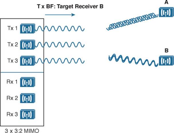
Figure 2-8 Using Transmit Beamforming to Target a Specific Receiving Device
The location and RF conditions can be unique for each receiver in an area. Therefore, transmit beamforming can use explicit feedback from an 802.11n device at the far end, enabling the transmitter to make the appropriate adjustments to the transmitted signal phase. As T×BF information is collected about each far end device, a transmitter can keep a table of the devices and phase adjustments so that it can send focused transmissions to each one dynamically. Although the feedback process sounds straightforward, it is complex to implement. The 802.11n amendment allowed four different feedback mechanisms to be used. To date, no practical feedback mechanism has been implemented due to compatibility issues among vendors and mechanisms.
Cisco also offers ClientLink, which performs a similar transmit beamforming function; however, ClientLink does not require explicit feedback from an 802.11n device at all. Based on data that is received from a far end device, the phase values can be calculated and performed on data transmissions that are returned to it. In this case, the far end device can be 802.11n or legacy 802.11a/g.
Maximal-Ratio Combining
When an RF signal is received on a device, it may look very little like the original transmitted signal. The signal may be degraded or distorted due to a variety of conditions. If that same signal can be transmitted over multiple antennas, as in the case of a MIMO device, then 802.11n can attempt to restore it to its original state.
An 802.11n device can use multiple antennas and radio chains to receive the multiple transmitted copies of the signal. One copy might be better than the others, or one copy might be better for a time, and then become worse than the others. In any event, 802.11n offers maximal-ratio combining (MRC), a feature that can combine the copies to produce one signal that represents the best version at any given time. The end result is a reconstructed signal with an improved SNR and receiver sensitivity.
802.11n Modulation and Coding Schemes
Recall that 802.11g and 802.11a are both based on OFDM and can use binary phase shift keying (BPSK), quadrature phase shift keying (QPSK), 16-QAM (quadrature amplitude modulation), and 64-QAM modulation schemes. Depending on conditions affecting the RF signal, wireless devices can choose one of the eight possible modulation and coding schemes. The 802.11n amendment is somewhat backward compatible with 802.11a and 802.11g, as it supports the same eight schemes. However, as the schemes are applied to an increasing number of spatial streams, the number of combinations multiplies.
802.11n supports a total of 32 possible schemes (8 per spatial stream)—so many that they are known by a modulation and coding scheme (MCS) index number. Beyond that, channel aggregation and guard interval selection add even more variables to the mix. In all, 802.11n has 128 possible data rates. For your reference, Appendix B, “Modulation and Coding Schemes,” lists all of the MCS and data rates.
802.11ac
The many features and high throughput of 802.11n might make it seem like the end-all wireless LAN technology. As with most any aspect of computing, the current state of the art is never good enough. The 802.11ac amendment, finalized in 2013, takes the best of 802.11n and offers a new generation that is much faster and more scalable. The goal is to bring wireless on a par with Gigabit Ethernet through a set of capabilities known as very high throughput (VHT). Once 802.11ac is fully implemented, it should support a maximum data rate of 6.93 Gbps! Some of the most notable improvements are outlined in the list that follows and further described in the ensuing sections. As you read through the improvements, you might notice that they sound familiar from the list of 802.11n features, but are greatly enhanced.
![]()
![]() Better channel aggregation—40-MHz bonded channels can be bonded again into channels that are 80 or 160 MHz wide. Because of the extensive use of channels, 802.11ac can be used only in the 5-GHz band.
Better channel aggregation—40-MHz bonded channels can be bonded again into channels that are 80 or 160 MHz wide. Because of the extensive use of channels, 802.11ac can be used only in the 5-GHz band.
![]() More dense modulation—256-QAM is used to modulate the RF signal in 256 different ways, taking more data at one time and boosting throughput.
More dense modulation—256-QAM is used to modulate the RF signal in 256 different ways, taking more data at one time and boosting throughput.
![]() MAC layer efficiency—More data can be aggregated with less overhead.
MAC layer efficiency—More data can be aggregated with less overhead.
![]() Explicit T×BF—To simplify and scale transmit beamforming, only a single feedback method is supported.
Explicit T×BF—To simplify and scale transmit beamforming, only a single feedback method is supported.
![]() Scalable MIMO—Up to eight spatial streams can be used.
Scalable MIMO—Up to eight spatial streams can be used.
![]() Multi-user MIMO (MU-MIMO)—An 802.11ac access point (AP) can send multiple frames to multiple receiving devices simultaneously.
Multi-user MIMO (MU-MIMO)—An 802.11ac access point (AP) can send multiple frames to multiple receiving devices simultaneously.
Robust Channel Aggregation
The 5-GHz band is made up of many channels, each one 20 MHz wide, as illustrated in Figure 2-9, where 802.11a must always use 20-MHz channels. One improvement with 802.11n is that two channels can be aggregated, forming a single 40-MHz channel, to increase throughput. The 802.11ac amendment supports an even better channel aggregation scheme, where the channel width can be 20, 40, 80, or 160 MHz. As always, to support efficient roaming and to minimize neighboring channel interference, the channels should not overlap. With 23 available channels, the number of non-overlapping aggregated channels decreases as the channel width increases. For example, there are only eleven 40-MHz channels, five 80-MHz channels, and two 160-MHz channels available.
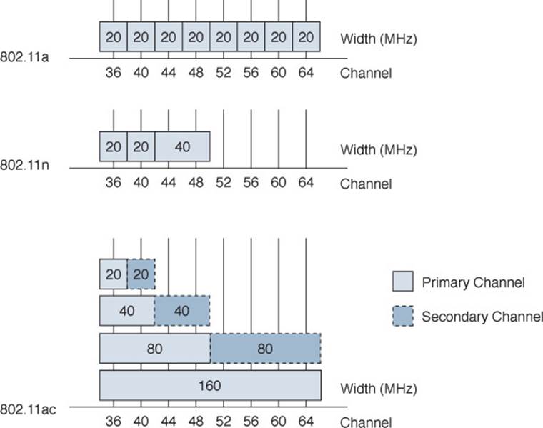
Figure 2-9 Channel Width Comparison Between 802.11a, 802.11n, and 802.11ac
To maximize channel use, 802.11ac offers something really clever—the channel width can vary dynamically, on a frame-by-frame basis. This means that wide channels can overlap within the band, but cannot be used at the same time. Every transmission does not normally require a wide channel, so the channel space can be negotiated for each frame. If a wide channel is needed and is currently available, it can be used. If some fraction of it is already in use, then the remainder can be claimed for a transmission.
Suppose two APs are located in the same general area so that their cells overlap. Ideally, the two APs should operate on separate non-overlapping channels to minimize co-channel and neighboring channel interference. As the channel layout in Figure 2-10 shows, the two APs can use their assigned 20- and 40-MHz channels at any time without interfering with each other. However, notice that their 80- and 160-MHz channels do overlap completely. Either AP can claim the wider channel and transmit as long as the other AP (or some other device) is not currently transmitting there.
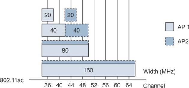
Figure 2-10 Channel Aggregation and Dynamic Use with 802.11ac
Contention for a wide channel is handled through the use of the Request-to-Send (RTS) and Clear-to-Send (CTS) frames. If one AP is ready to transmit on an aggregated channel, it first sends an RTS frame on its primary 20-MHz channel and duplicates the RTS frame on all other 20-MHz channels that are components of the wider channel. By doing so, the AP is requesting use of the full channel width for one frame. The intended receiver checks to see if the full channel is free, then replies with CTS frames on each free 20-MHz component channel. The AP can then gauge which parts of the wide channel are free and transmit there.
Dense Modulation
Devices using 802.11ac can take advantage of 256-QAM modulation for higher data throughput. The difference between 256-QAM and 64-QAM (the best 802.11n offering) is about 25 percent higher data rates. However, you cannot simply expect to use 256-QAM in all circumstances, because it also requires a higher SNR, which usually means the client must be located closer to the AP.
The 802.11ac amendment also simplifies the list of modulation and coding scheme (MCS) choices that can be used between an AP and a client. There are 10 possible MCS values, listed in Table 2-11, as opposed to 32 or more choices with 802.11n. Notice that the 802.11ac MCS choices are tied only to the actual modulation and coding schemes used—not to the number of spatial streams or the channel width, as 802.11n uses. All of those parameters still work together to produce a long list of possible maximum data rates, but 802.11ac tends to loosen the restrictions so that each parameter can be selected independently.
![]()
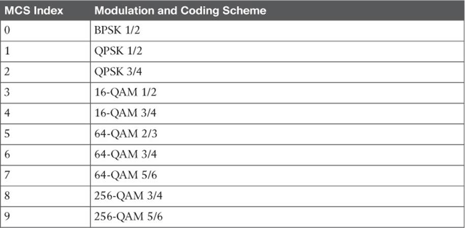
Table 2-11 IEEE 802.11ac Modulation and Coding Schemes
You can find complete MCS and data rate information for both 802.11ac and 802.11n in Appendix B.
MAC Layer Efficiency
To improve the efficiency of frame transmission, 802.11n introduced frame aggregation. In a nutshell, more data can be sent in a single wireless frame, avoiding the 802.11 header overhead that would be required for each smaller frame. To build an aggregated frame, the sender places multiple payloads (known as MAC Service Data Units, or MSDUs) inside one 802.11 frame (a PLCP Service Data Unit, or PSDU, with one header and one trailer) that will be transmitted over the air.
Regardless of the wireless protocol being used, each individual frame (MSDU) inside the aggregated frame is limited to 2304 bytes. How large can the aggregated frame be? In traditional wired networks, the transmitted frame would be limited to the MTU size. With wireless networks, devices contend for air time so the frame size is bounded by a time limit of about 5.5 milliseconds. At 802.11n data speeds, 64 KB can be transmitted in 5.5 ms; at the maximum 802.11ac speed, about 4.5 MB can be sent as a single frame!
Rather than marking each frame as individual or aggregated, 802.11ac expects every frame to be an aggregate. Each MSDU within an 802.11ac frame contains a familiar MAC header and MAC addresses.
Like 802.11n, 802.11ac supports two guard intervals—400 and 800 nanoseconds.
Explicit Transmit Beamforming
Transmit beamforming is an attempt to “focus” or direct a transmission toward a specific client by adjusting the phase of several spatial streams. With 802.11n, transmit beamforming can be either explicit, requiring feedback from the client, or passive, where the AP infers information about the client from received signals. The explicit method must be negotiated between the AP and the client, but no standardized or common methods have been developed—especially ones that are compatible across multiple vendors.
The 802.11ac amendment specifies only one transmit beamforming method, called Null Data Packet (NDP). The AP first transmits an NDP Announcement frame to identify itself and any 802.11ac clients that might be present within range. Any interested clients respond, while all other clients simply ignore the announcement. The AP then sends an NDP frame as a way to “sound” a channel. When the clients receive the NDP, they compute a matrix of information about the channel conditions and how the NDP was received and return that matrix to the AP. From that point on, the AP can make beamforming adjustments that are customized for each 802.11ac client each time it transmits a frame.
Scalable MIMO
The 802.11n amendment introduced multiple spatial streams that can be used to multiplex data across several different paths from the transmitter to the receiver. Each path requires a separate radio chain and antenna, as well as physical conditions that create multipath signal propagation. 802.11n supports up to four spatial streams on a device. The 802.11ac amendment takes this concept even further—up to eight spatial streams can be used.
Such a large number of spatial streams brings some challenges though. Each radio chain requires physical space for circuitry and an antenna, as well as additional power. Mobile devices might not easily be able to support many radio chains due to their small size and limited battery power.
Multi-user MIMO
Recall that 802.11n supports MIMO using multiple spatial streams simultaneously—all dedicated to data transfer between an AP and one wireless user. 802.11ac can take that concept even further by sending data in the downstream direction, from an AP across multiple spatial streams tomultiple users simultaneously. Naturally, the multipath conditions must be conducive for the spatial streams to reach the intended clients, wherever they are located at the time. Explicit transmit beamforming comes in very handy for this purpose, as it enables the AP to tailor transmissions to each specific client. MU-MIMO is not possible from a wireless client toward other devices in the upstream direction.
MU-MIMO also brings a heavy signal processing burden on the transmitter in order to multiplex the wireless frames across the spatial streams.
802.11ac Implementation
After reading through the list of 802.11ac improvements and enhancements, you might think some or all of them would be difficult to implement. In fact, 802.11ac was designed to be a bit too progressive for the wireless technology at the time. Rather than waiting on hardware technologies to catch up before the amendment was ratified, 802.11ac has been broken up into two waves or phases. Wave 1 includes almost every feature, with performance limits that are reasonable for current hardware. Wave 2 begins in 2016, giving hardware developers time to produce more advanced products that will extend the Wave 1 features further. Table 2-12 lists the features and capabilities offered in each of the two waves, as tested by the Wi-Fi Alliance.
![]()
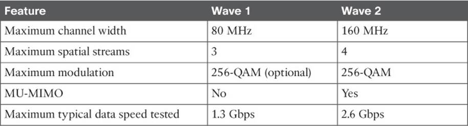
Table 2-12 Features and Capabilities Tested in IEEE 802.11ac Waves
Tip
As discussed earlier in this chapter, 802.11ac was expected to support up to eight spatial streams and a maximum data speed of 6.93 Gbps. Why does Table 2-12 list Wave 2 with four spatial streams and a maximum data speed of 2.6 Gbps? Wave 2 is not necessarily the finish line for 802.11ac development; it is the second milestone. Past that, there should be further development to bring about four more spatial streams, which should bring the data speed up to 6.93 Gbps accordingly.
802.11 in Other Frequency Bands
Throughout this book, you will find references to the two main frequency bands, 2.4 and 5 GHz, but few others. That is because the bulk of the 802.11 standard and its amendments have been focused on using those common public bands—not because 802.11 cannot be used elsewhere in the frequency spectrum.
You should be aware of several amendments that apply 802.11 to other bands too, including the following:
![]() 802.11ad—A multi-gigabit technology that allows devices to operate in the unlicensed 60-GHz band. At that frequency, signals tend to propagate less through physical objects. The end result is increased data rates but reduced range, making 802.11ad more suitable for very high speed wireless links within a room.
802.11ad—A multi-gigabit technology that allows devices to operate in the unlicensed 60-GHz band. At that frequency, signals tend to propagate less through physical objects. The end result is increased data rates but reduced range, making 802.11ad more suitable for very high speed wireless links within a room.
![]() 802.11af—Allows unlicensed 802.11 operation in the spectrum known historically as the Television White Space (TVWS), between 54 and 790 MHz. Many of 802.11ac’s features are leveraged, such as OFDM, 10 MCS choices, channel aggregation, multiple spatial streams, and MU-MIMO. The lower frequencies used tend to penetrate physical objects better, improving the effective range.
802.11af—Allows unlicensed 802.11 operation in the spectrum known historically as the Television White Space (TVWS), between 54 and 790 MHz. Many of 802.11ac’s features are leveraged, such as OFDM, 10 MCS choices, channel aggregation, multiple spatial streams, and MU-MIMO. The lower frequencies used tend to penetrate physical objects better, improving the effective range.
![]() 802.11ah—Allows devices to communicate on frequencies below 1 GHz. The emphasis is on a greater range (1 km), lower power consumption, and connectivity to a large number of devices dispersed over the coverage area.
802.11ah—Allows devices to communicate on frequencies below 1 GHz. The emphasis is on a greater range (1 km), lower power consumption, and connectivity to a large number of devices dispersed over the coverage area.
Wi-Fi Alliance
All wireless LAN products must adhere to the IEEE 802.11 set of standards to be compatible with each other. Even though the 802.11 standards are very thorough and lengthy, it is still possible for one manufacturer to build a product based on one interpretation of a standard feature, while another manufacturer works with a different interpretation. This is especially true when products are developed while an 802.11 amendment is still in draft form. In addition, manufacturers are not obligated to implement every function described in a standard; they may pick and choose certain parts or implement the entire standard, and may even add in some proprietary features.
The Wi-Fi Alliance (http://wi-fi.org) is a nonprofit industry association made up of wireless manufacturers around the world, all devoted to promoting wireless use. To address the problem of incompatible wireless products, the Wi-Fi Alliance introduced the Wi-Fi CERTIFIED program in 2000. Wireless products are tested in authorized testing labs against stringent criteria that represent correct implementation of a standard. If a product passes the tests, then it is certified and receives a Wi-Fi CERTIFIED stamp of approval, using the logo shown in Figure 2-11.
Figure 2-11 Wi-Fi Alliance Certification Logo
The Wi-Fi Alliance has many certification programs that are based around common sets of features—not just specific 802.11 amendments. The end result is an effort to make Wi-Fi better by assuring a better user experience. The following list describes some example programs:
![]() Wi-Fi Certified n—Products using 802.11n correctly implement features like multiple spatial streams, channel aggregation, block acknowledgement, and dual-band operation.
Wi-Fi Certified n—Products using 802.11n correctly implement features like multiple spatial streams, channel aggregation, block acknowledgement, and dual-band operation.
![]() Wi-Fi Certified ac—Products using 802.11ac correctly implement all of its features, including each of the two 802.11ac waves.
Wi-Fi Certified ac—Products using 802.11ac correctly implement all of its features, including each of the two 802.11ac waves.
![]() Wi-Fi Direct—Products can interoperate without the use of an AP for printing, display, and content sharing.
Wi-Fi Direct—Products can interoperate without the use of an AP for printing, display, and content sharing.
![]() WPA2—Products correctly implement premium personal and enterprise wireless security features.
WPA2—Products correctly implement premium personal and enterprise wireless security features.
![]() Protected Management Frames—Extends premium security to protect Wi-Fi management frames between an AP and wireless devices.
Protected Management Frames—Extends premium security to protect Wi-Fi management frames between an AP and wireless devices.
![]() Wi-Fi Protected Setup (WPS)—Products offer an easy-to-use initial configuration of wireless security features.
Wi-Fi Protected Setup (WPS)—Products offer an easy-to-use initial configuration of wireless security features.
![]() Wi-Fi Multimedia (WMM)—Wi-Fi products interoperate to prioritize and handle various types of traffic with quality-of-service (QoS) mechanisms.
Wi-Fi Multimedia (WMM)—Wi-Fi products interoperate to prioritize and handle various types of traffic with quality-of-service (QoS) mechanisms.
![]() Voice-Personal—Tests the performance of Wi-Fi devices to make sure they can deliver good voice quality wirelessly.
Voice-Personal—Tests the performance of Wi-Fi devices to make sure they can deliver good voice quality wirelessly.
![]() Voice-Enterprise—Tests the ability of Wi-Fi devices to deliver good voice quality, efficient roaming, and robust management while voice-capable devices are mobile.
Voice-Enterprise—Tests the ability of Wi-Fi devices to deliver good voice quality, efficient roaming, and robust management while voice-capable devices are mobile.
Tip
Remember that the IEEE develops and maintains the 802.11 set of standards. The Wi-Fi Alliance tests and certifies product interoperability and the feature set functionality according to the IEEE standards and its own technical specifications.
Exam Preparation Tasks
As mentioned in the section, “How to Use This Book,” in the Introduction, you have a couple of choices for exam preparation: the exercises here, Chapter 21, “Final Review,” and the exam simulation questions on the DVD.
Review All Key Topics
Review the most important topics in this chapter, noted with the Key Topic icon in the outer margin of the page. Table 2-13 lists a reference of these key topics and the page numbers on which each is found.
![]()
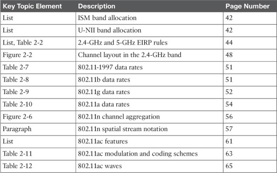
Table 2-13 Key Topics for Chapter 2
802.11 Protocol Summary
Table 2-14 lists each of the 802.11 protocols by their amendment nomenclature. You can use this table to review and compare the basic specifications of each. As you review, keep in mind that the maximum data rate is most impacted by a combination of the channel width, the number of spatial streams, and the modulation density.
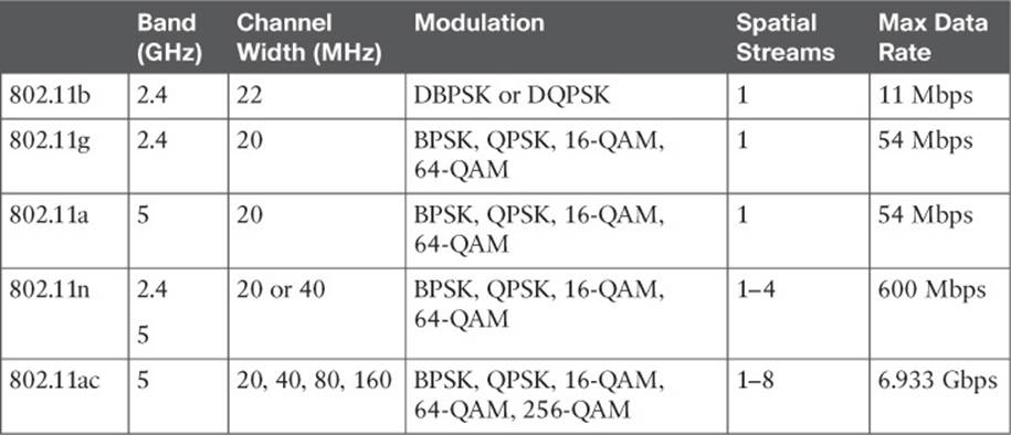
Table 2-14 802.11 Protocol Summary
Define Key Terms
Define the following key terms from this chapter and check your answers in the glossary:
block acknowledgment
channel aggregations
guard interval (GI)
high throughput (HT)
intersymbol interference (ISI)
maximal-ratio combining (MRC)
Null Data Packet (NDP)
protection mechanism
spatial multiplexing
spatial stream
transmit beamforming (T×BF)
All materials on the site are licensed Creative Commons Attribution-Sharealike 3.0 Unported CC BY-SA 3.0 & GNU Free Documentation License (GFDL)
If you are the copyright holder of any material contained on our site and intend to remove it, please contact our site administrator for approval.
© 2016-2026 All site design rights belong to S.Y.A.