CCNA Wireless 200-355 Official Cert Guide (2016)
Chapter 8. Understanding Cisco Wireless Architectures
This chapter covers the following topics:
![]() Distributed Architectures—This section discusses a wireless network formed by autonomous access points and managed either individually or through a cloud-based means.
Distributed Architectures—This section discusses a wireless network formed by autonomous access points and managed either individually or through a cloud-based means.
![]() Split-MAC Architectures—This section describes wireless networks that can be built from lightweight access points and wireless LAN controllers.
Split-MAC Architectures—This section describes wireless networks that can be built from lightweight access points and wireless LAN controllers.
![]() Cisco Wireless Network Building Blocks—This section covers the Cisco devices that are necessary to build a wireless network with one of the common architectures.
Cisco Wireless Network Building Blocks—This section covers the Cisco devices that are necessary to build a wireless network with one of the common architectures.
This chapter covers the following exam topics:
![]() 3.0—Implementing a Wireless Network
3.0—Implementing a Wireless Network
![]() 3.1—Describe the various Cisco wireless architectures
3.1—Describe the various Cisco wireless architectures
![]() 3.1a—Cloud
3.1a—Cloud
![]() 3.1b—Autonomous
3.1b—Autonomous
![]() 3.1c—Split MAC
3.1c—Split MAC
![]() 3.1c(i)—FlexConnect
3.1c(i)—FlexConnect
![]() 3.1c(ii)—Centralized
3.1c(ii)—Centralized
![]() 3.1c(iii)—Converged
3.1c(iii)—Converged
![]() 4.0 Operating a Wireless Network
4.0 Operating a Wireless Network
![]() 4.3 Distinguish different lightweight AP modes
4.3 Distinguish different lightweight AP modes
In previous chapters, you learned about how a single access point (AP) can provide a basic service set (BSS) for a cell area and how multiple APs can be connected to form an extended service set (ESS) for a larger network. In this chapter, you will learn more about different approaches or architectures that allow APs to be networked together for an enterprise. You will also learn how some architectures are more scalable than others, and how to manage each type of wireless network architecture.
“Do I Know This Already?” Quiz
The “Do I Know This Already?” quiz allows you to assess whether you should read this entire chapter thoroughly or jump to the “Exam Preparation Tasks” section. If you are in doubt about your answers to these questions or your own assessment of your knowledge of the topics, read the entire chapter. Table 8-1 lists the major headings in this chapter and their corresponding “Do I Know This Already?” quiz questions. You can find the answers in Appendix A, “Answers to the ‘Do I Know This Already?’ Quizzes.”
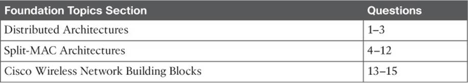
Table 8-1 “Do I Know This Already?” Section-to-Question Mapping
Caution
The goal of self-assessment is to gauge your mastery of the topics in this chapter. If you do not know the answer to a question or are only partially sure of the answer, you should mark that question as wrong for purposes of the self-assessment. Giving yourself credit for an answer you correctly guess skews your self-assessment results and might provide you with a false sense of security.
1. Which one of the following terms best describes a Cisco wireless access point that operates in a standalone, independent manner?
a. Autonomous AP
b. Independent AP
c. Lightweight AP
d. Embedded AP
2. Suppose that an autonomous AP is used to support wireless clients. Which one of the following paths would traffic usually take when passing from one wireless client to another?
a. Through the AP only
b. Through the AP and its controller
c. Through the controller only
d. None of these answers (because traffic can go directly over the air)
3. The Cisco Meraki cloud-based APs are most accurately described by which one of the following statements?
a. Autonomous APs joined to a WLC
b. Autonomous APs centrally managed
c. Lightweight APs joined to a WLC
d. Lightweight APs centrally managed
4. Suppose that a lightweight AP in default local mode is used to support wireless clients. Which one of the following paths would traffic usually take when passing from one wireless client to another?
a. Through the AP only
b. Through the AP and its controller
c. Through the controller only
d. None of these answers (because traffic must go directly over the air)
5. A lightweight access point is said to participate in which one of the following architectures?
a. Light-MAC
b. Tunnel-MAC
c. Split-MAC
d. Big-MAC
6. How does a lightweight access point communicate with a wireless LAN controller?
a. Through an IPsec tunnel
b. Through a CAPWAP tunnel
c. Through a GRE tunnel
d. Directly over Layer 2
7. Which one of the following types of traffic is sent securely over a CAPWAP tunnel by default?
a. Control messages
b. Client data
c. DHCP requests
d. 802.11 beacons
8. Which one of the following is not needed for a lightweight AP in default local mode to be able to support three SSIDs that are bound to three VLANs?
a. A trunk link carrying three VLANs
b. An access link bound to a single VLAN
c. A WLC connected to three VLANs
d. A CAPWAP tunnel to a WLC
9. A centralized wireless network is built with one WLC and 32 lightweight APs. Which one of the following best describes the resulting architecture?
a. A direct Layer 2 path from the WLC to each of the 32 LAPs, all using the same IP subnet
b. A direct Layer 3 path from the WLC to each of the 32 LAPs, all using the same IP subnet
c. 32 CAPWAP tunnels daisy-chained between the LAPs, one CAPWAP tunnel to the WLC
d. 32 CAPWAP tunnels—one tunnel from the WLC to each LAP, with no IP subnet restrictions
10. A converged wireless network architecture has which one of the following unique features?
a. An access layer switch can also function as an AP.
b. All WLCs are converged into one device.
c. Large groups of APs connect to a single access layer switch.
d. An access layer switch can also function as a WLC.
11. Which one of the following wireless architectures usually requires the most controllers to support the same number of lightweight APs?
a. Autonomous
b. Cloud-based
c. Converged
d. Centralized
12. The FlexConnect architecture is normally used in which of the following scenarios?
a. APs located in a main campus
b. APs located in remote branch sites
c. APs located in the cloud
d. None of the above, because FlexConnect is a Catalyst switch feature
13. A Cisco centralized wireless network is built with 1000 lightweight APs and a Cisco 5520 WLC. Suppose wireless coverage needs to be offered in several additional buildings, which will double the number of APs in use. Which of the following strategies would work? (Choose all that apply.)
a. Add another 5520 WLC.
b. Replace the 5520 with a WLC that offers a greater AP capacity.
c. The 5520 will become full, so replace the APs with models that can cover twice the area.
d. Do nothing; you can have only one WLC in a network and no other model offers more APs than the 5520.
14. Which of the following Cisco Aironet AP models should you choose if you expect to see 802.11ac Wave 2 clients in the near future? (Choose all that apply.)
a. 1700
b. 1850
c. 2700
d. 3700
15. Five Cisco Catalyst 3850 switches are configured as a single switch stack. The switches are also configured as a controller to support a converged wireless network. What is the maximum number of lightweight APs that can be joined to the switch stack?
a. 10
b. 50
c. 500
d. 1000
Foundation Topics
You can build a Cisco wireless network according to several different architectures that are described in the sections that follow. As you work through this chapter, think about how each architecture can be applied to specific environments—how easy it would be to manage, deploy, and troubleshoot the network, how the APs can be controlled, and how data would move through the network.
Distributed Architectures
An AP’s primary function is to bridge wireless data from the air to a normal wired network. An AP can accept “connections” from a number of wireless clients so that they become members of the LAN, as if the same clients were using wired connections.
APs act as the central point of access (hence the AP name), controlling client access to the wireless LAN. An autonomous AP is self-contained; it is equipped with both wired and wireless hardware so that the wireless client associations can be terminated onto a wired connection locally at the AP. The APs and their data connections must be distributed across the coverage area and across the network. They can be managed in an autonomous fashion or through a cloud-based mechanism.
Autonomous Architecture
Autonomous APs are self-contained, each offering one or more fully functional, standalone basic service sets (BSSs). They are also a natural extension of a switched network, connecting wireless service set identifiers (SSIDs) to wired virtual LANs (VLANs) at the access layer. Figure 8-1shows the basic architecture; even though only four APs are shown, a typical enterprise network could consist of hundreds or thousands of APs.
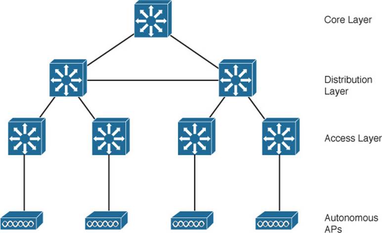
Figure 8-1 Wireless Network Architecture with Autonomous APs
What exactly does an autonomous AP need to become a part of the network? Refer to Figure 8-2, which focuses on just one AP and its connections. The wireless network consists of two SSIDs: wlan100 and wlan200. These correspond to wired VLANs 100 and 200, respectively. The VLANs must be trunked from the distribution layer switch (where routing commonly takes place) to the access layer, where they are extended further over a trunk link to the AP.
![]()
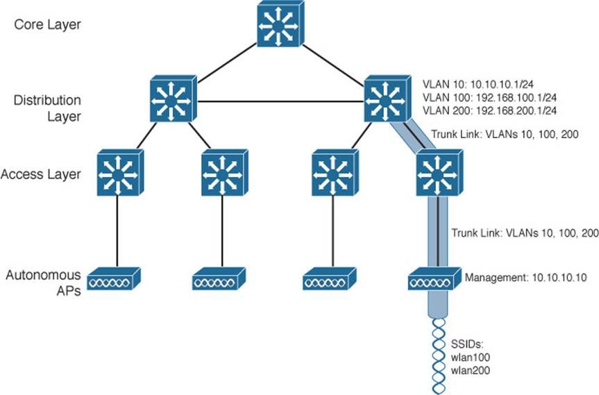
Figure 8-2 Network Architecture Supporting a Single Autonomous AP
An autonomous AP offers a short and simple path for data to travel between the wireless and wired networks. As Figure 8-3 shows, data has to travel only through the AP to reach the network on the other side. Two wireless users that are associated to the same autonomous AP can reach each other through the AP, without having to pass up into the wired network. As you work through the wireless architectures discussed in the rest of the chapter, notice the data path that is required for each.
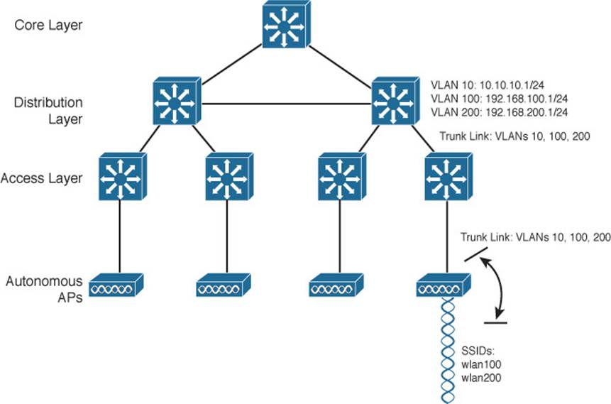
Figure 8-3 Data Path Between Autonomous Wireless and Wired Networks
An autonomous AP must also be configured with a management IP address (10.10.10.10) so that you can remotely manage it. After all, you will want to configure SSIDs, VLANs, and many RF parameters like the channel and transmit power to be used. The management address is not normally part of any of the data VLANs, so a dedicated management VLAN (VLAN 10 in the figures) must be added to the trunk links to reach the AP. Each AP must be configured and maintained individually unless you leverage a management platform such as Cisco Prime Infrastructure.
Because the data and management VLANs may need to reach every autonomous AP, the network configuration and efficiency can become cumbersome as the network scales. For example, you will likely want to offer the same SSID on many APs so that wireless clients can associate with that SSID in most any location or while roaming between two APs. You might also want to extend the corresponding VLAN to each and every AP so that clients do not have to request a new IP address for each new association.
Because SSIDs and their VLANs must be extended at Layer 2, you should consider how they are extended throughout the switched network. Figure 8-4 shows an example of a single VLAN’s extent in the data plane. Working top to bottom, follow VLAN 100 as it reaches through the network. VLAN 100 is routed within the distribution layer and must be carried over trunk links to the access layer switches and then to each autonomous AP. In effect, VLAN 100 must extend end to end across the whole infrastructure—something that is considered a bad practice.
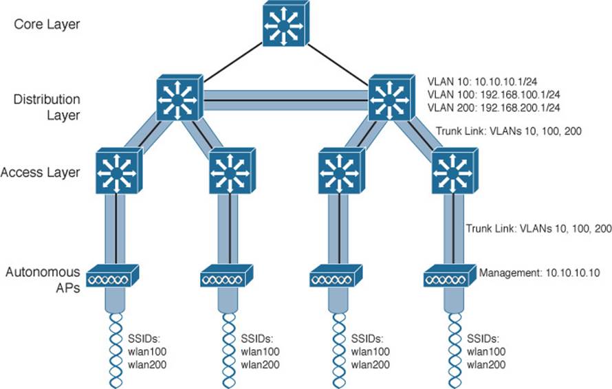
Figure 8-4 Extent of a Data VLAN in a Network of Autonomous APs
That might sound straightforward until you have to add a new VLAN and configure every switch and AP in your network. Even worse, suppose your network has redundant links between each layer of switches. The Spanning Tree Protocol (STP) running on each switch becomes a vital ingredient to prevent bridging loops from forming and corrupting the network. For these reasons, client roaming across autonomous APs is typically limited to the Layer 2 domain, or the extent of a single VLAN. As the wireless network expands, the infrastructure becomes more difficult to configure correctly and becomes less efficient.
Cloud-based Architecture
Recall that an autonomous AP needs quite a bit of configuration and management. To help manage more and more autonomous APs as the wireless network grows, you could place an AP management platform such as Cisco Prime Infrastructure in a central location within the enterprise. The management platform would need to be purchased, configured, and maintained too.
A simpler approach is a cloud-based architecture, where the AP management function is pushed out of the enterprise and into the Internet cloud. Cisco Meraki is cloud-based and offers centralized management of wireless, switched, and security network built from Meraki products. For example, through the cloud networking service, you can manage APs, monitor wireless performance and activity, generate reports, and so on.
Cisco Meraki APs can be deployed automatically, once you register with the Meraki cloud. Each AP will contact the cloud when it powers up and will self-configure. From that point on, you can manage the AP through the Meraki cloud dashboard.
Figure 8-5 illustrates the basic cloud-based architecture. Notice that the network is arranged identically to that of the autonomous AP network. That is because the APs in a cloud-based network are all autonomous, too. The most visible difference is that all of the APs are managed, controlled, and monitored centrally from the cloud.
![]()
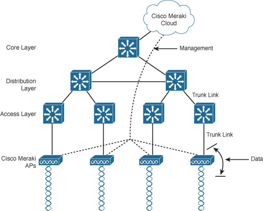
Figure 8-5 Cisco Meraki Cloud-Based Wireless Network Architecture
From the cloud, you can push out code upgrades and configuration changes to the APs in the enterprise. The Cisco Meraki cloud also adds the intelligence needed to instruct each AP on which channel and transmit power level to use. It can also collect information from all of the APs about things such as RF interference, rogue or unexpected wireless devices that were overheard, and wireless usage statistics.
Finally, there are a couple of things you should observe about the cloud-based architecture. The data path from the wireless network to the wired network is very short; the autonomous AP links the two networks. Data to and from wireless clients does not have to travel up into the cloud and back; the cloud is used to bring management functions into the data plane.
Also, notice that the network in Figure 8-5 consists of two distinct paths—one for data traffic and another for management traffic, corresponding to the following two functions:
![]() A control plane—Traffic used to control, configure, manage, and monitor the AP itself
A control plane—Traffic used to control, configure, manage, and monitor the AP itself
![]() A data plane—End-user traffic passing through the AP
A data plane—End-user traffic passing through the AP
This division will become important in the following sections as other types of architecture are discussed.
Split-MAC Architectures
Because autonomous APs are...well, autonomous, managing their RF operation can be quite difficult. As a network administrator, you are in charge of selecting and configuring the channel used by each AP and detecting and dealing with any rogue APs that might be interfering. You must also manage things such as the transmit power level to make sure that the wireless coverage is sufficient, does not overlap too much, and there aren’t any coverage holes—even when an AP’s radio fails.
Managing wireless network security can also be difficult. Each autonomous AP handles its own security policies, with no central point of entry between the wireless and wired networks. That means there is no convenient place to monitor traffic for things such as intrusion detection and prevention, quality of service, bandwidth policing, and so on.
To overcome the limitations of distributed autonomous APs, many of the functions found within autonomous APs have to be shifted toward some central location. In Figure 8-6, most of the activities performed by an autonomous AP on the left are broken up into two groups—real-time processes on the top and management processes on the bottom.
![]()
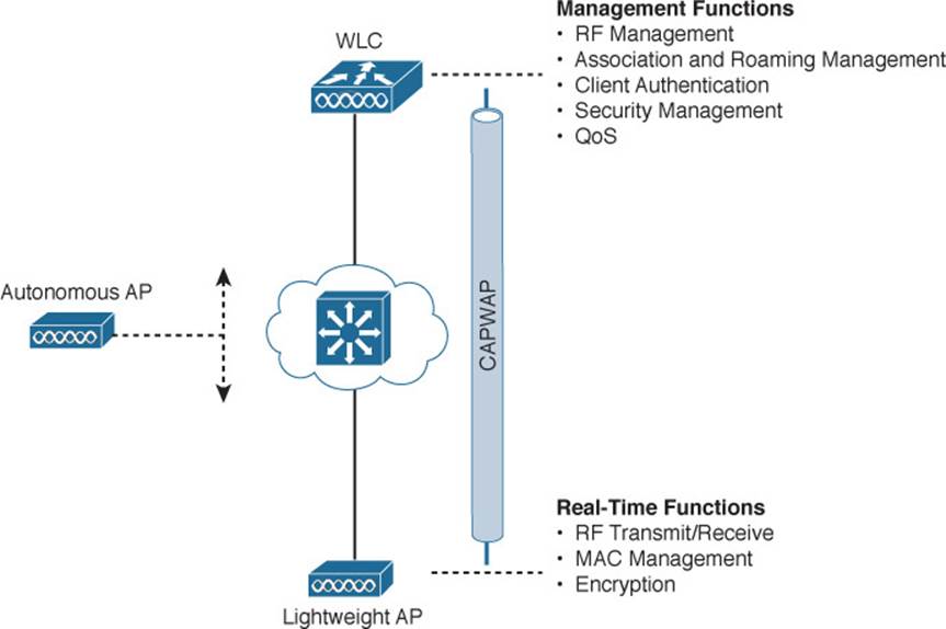
Figure 8-6 Autonomous Versus Lightweight Access Point
The real-time processes involve sending and receiving 802.11 frames, beacons, and probe messages. 802.11 data encryption is also handled in real time, on a per-packet basis. The AP must interact with wireless clients on some low level, known as the media access control (MAC) layer. These functions must stay with the AP, closest to the clients.
The management functions are not integral to handling frames over the RF channels, but are things that should be centrally administered. Therefore, those functions are moved to a centrally located platform away from the AP.
In the Cisco unified wireless network, a lightweight access point (LAP) performs only the real-time 802.11 operation. The LAP gets its name because the code image and the local intelligence are stripped down, or lightweight, compared to the traditional autonomous AP.
The management functions are usually performed on a wireless LAN controller (WLC), which controls many LAPs. This is shown in the bottom right portion of Figure 8-6. Notice that the LAP is left with duties in Layers 1 and 2, where frames are moved into and out of the RF domain. The LAP becomes totally dependent on the WLC for every other WLAN function, such as authenticating users, managing security policies, and even selecting RF channels and output power.
Tip
Remember that a lightweight AP cannot normally operate on its own—it is very dependent upon a WLC somewhere in the network. The only exception is the FlexConnect architecture, which is discussed later in this chapter.
The LAP-WLC division of labor is known as a split-MAC architecture, where the normal MAC operations are pulled apart into two distinct locations. This occurs for every LAP in the network; each one must boot and bind itself to a WLC to support wireless clients. The WLC becomes the central hub that supports a number of LAPs scattered about in the network.
How does an LAP bind with a WLC to form a complete working access point? The two devices must use a tunneling protocol between them, to carry 802.11-related messages and also client data. Remember that the LAP and WLC can be located on the same VLAN or IP subnet, but they do not have to be. Instead, they can be located on two entirely different IP subnets in two entirely different locations.
The Control and Provisioning of Wireless Access Points (CAPWAP) tunneling protocol makes this all possible by encapsulating the data between the LAP and WLC within new IP packets. The tunneled data can then be switched or routed across the campus network. As Figure 8-7 shows, the CAPWAP relationship actually consists of the following two tunnels:
![]() CAPWAP control messages—Used for exchanges that are used to configure the LAP and manage its operation. The control messages are authenticated and encrypted, so that the LAP is securely controlled by only the WLC, then transported using UDP port 5246 at the controller.
CAPWAP control messages—Used for exchanges that are used to configure the LAP and manage its operation. The control messages are authenticated and encrypted, so that the LAP is securely controlled by only the WLC, then transported using UDP port 5246 at the controller.
![]() CAPWAP data—Used for packets traveling to and from wireless clients that are associated with the LAP. Data packets are transported using UDP port 5247 at the controller, but are not encrypted by default. When data encryption is enabled for an LAP, packets are protected with Datagram Transport Layer Security (DTLS).
CAPWAP data—Used for packets traveling to and from wireless clients that are associated with the LAP. Data packets are transported using UDP port 5247 at the controller, but are not encrypted by default. When data encryption is enabled for an LAP, packets are protected with Datagram Transport Layer Security (DTLS).
![]()
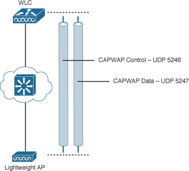
Figure 8-7 Linking an LAP and WLC with CAPWAP
Tip
CAPWAP is defined in RFCs 5415, 5416, 5417, and 5418. CAPWAP is based on the Lightweight Access Point Protocol (LWAPP), which was a legacy Cisco proprietary solution.
Every LAP and WLC must also authenticate each other with digital certificates. An X.509 certificate is preinstalled in each device when it is purchased. By using certificates behind the scenes, every device is properly authenticated before becoming part of the wireless network. This process helps assure that no rogue non-CAPWAP AP can be introduced into the network. The LAP-WLC association is covered in greater detail in Chapter 11, “Understanding Controller Discovery.”
The CAPWAP tunneling allows the LAP and WLC to be separated geographically and logically. It also breaks the dependence on Layer 2 connectivity between them. For example, Figure 8-8 uses shaded areas to show the extent of VLAN 100. Notice how VLAN 100 exists at the WLC and in the air as SSID 100, near the wireless clients—but not in between the LAP and the WLC. Instead, traffic to and from clients associated with SSID 100 is transported across the network infrastructure encapsulated inside the CAPWAP data tunnel. The tunnel exists between the IP address of the WLC and the IP address of the LAP, which allows all of the tunneled packets to be routed at Layer 3.
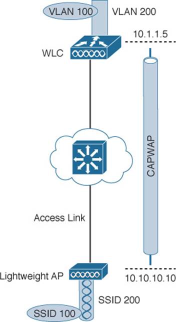
Figure 8-8 Extent of VLAN 100 in a Cisco Wireless Network
Also, notice how the LAP is known by only a single IP address 10.10.10.10. Because the LAP sits on the access layer where its CAPWAP tunnels terminate, it can use one IP address for both management and tunneling. No trunk link is needed because all of the VLANs it supports are encapsulated and tunneled.
As the wireless network grows, the WLC simply builds more CAPWAP tunnels to reach more APs. Figure 8-9 depicts a network with four LAPs. Each LAP has a control and a data tunnel back to the centralized WLC. SSID 100 can exist on every AP, and VLAN 100 can reach every AP through the network of tunnels.
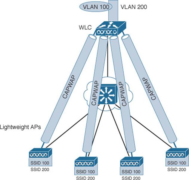
Figure 8-9 Using CAPWAP Tunnels to Connect LAPs to One Central WLC
Once CAPWAP tunnels are built from a WLC to one or more lightweight APs, the WLC can begin offering a variety of additional functions. Think of all the puzzles and shortcomings that were discussed for the traditional autonomous WLAN architecture as you read over the following list of WLC activities:
![]() Dynamic channel assignment—The WLC can automatically choose and configure the RF channel used by each LAP, based on other active access points in the area.
Dynamic channel assignment—The WLC can automatically choose and configure the RF channel used by each LAP, based on other active access points in the area.
![]() Transmit power optimization—The WLC can automatically set the transmit power of each LAP based on the coverage area needed.
Transmit power optimization—The WLC can automatically set the transmit power of each LAP based on the coverage area needed.
![]() Self-healing wireless coverage—If an LAP radio dies, the coverage hole can be “healed” by turning up the transmit power of surrounding LAPs automatically.
Self-healing wireless coverage—If an LAP radio dies, the coverage hole can be “healed” by turning up the transmit power of surrounding LAPs automatically.
![]() Flexible client roaming—Clients can roam between LAPs at either Layer 2 or Layer 3 with very fast roaming times.
Flexible client roaming—Clients can roam between LAPs at either Layer 2 or Layer 3 with very fast roaming times.
![]() Dynamic client load balancing—If two or more LAPs are positioned to cover the same geographic area, the WLC can associate clients with the least used LAP. This distributes the client load across the LAPs.
Dynamic client load balancing—If two or more LAPs are positioned to cover the same geographic area, the WLC can associate clients with the least used LAP. This distributes the client load across the LAPs.
![]() RF monitoring—The WLC manages each LAP so that it scans channels to monitor the RF usage. By listening to a channel, the WLC can remotely gather information about RF interference, noise, signals from neighboring LAPs, and signals from rogue APs or ad hoc clients.
RF monitoring—The WLC manages each LAP so that it scans channels to monitor the RF usage. By listening to a channel, the WLC can remotely gather information about RF interference, noise, signals from neighboring LAPs, and signals from rogue APs or ad hoc clients.
![]() Security management—The WLC can authenticate clients from a central service and can require wireless clients to obtain an IP address from a trusted DHCP server before allowing them to associate and access the WLAN.
Security management—The WLC can authenticate clients from a central service and can require wireless clients to obtain an IP address from a trusted DHCP server before allowing them to associate and access the WLAN.
![]() Wireless intrusion protection system—Leveraging its central location, the WLC can monitor client data to detect and prevent malicious activity.
Wireless intrusion protection system—Leveraging its central location, the WLC can monitor client data to detect and prevent malicious activity.
The split-MAC concept can be applied to several different network architectures, as described in the following sections. Each architecture places the WLC in a different location within the network—a choice that also affects how many WLCs are needed.
Centralized Wireless Network Architecture
Suppose you want to deploy a WLC to support multiple lightweight APs in your network. Where should you put the WLC? One approach is to locate the WLC in a central location so that you can maximize the number of APs joined to it. This tends to follow the concept that most of the resources users need to reach are located in a central location such as a data center or the Internet. Traffic to and from wireless users would travel over CAPWAP tunnels that reach into the center of the network, near the core, as shown in Figure 8-10. A centralized WLC also provides a convenient place to enforce security policies that affect all wireless users.
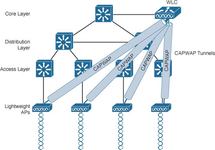
Figure 8-10 WLC Location in a Centralized Wireless Network
Figure 8-10 shows four LAPs joined to a single WLC. Your network might have more LAPs—many, many more. A large enterprise network might have thousands of LAPs connected to its access layer. Scalability then becomes an important factor in the centralized design. Each Cisco WLC model has a maximum number of LAPs that it supports. If you have more LAPs than the maximum, you will need to add more WLCs to the design, each located centrally.
Tip
Cisco offers WLC models that support a maximum of 75 LAPs up to 6000 LAPs. Each model also has a maximum number of wireless clients. The cost of the WLC is generally proportional to the maximum number of LAPs and clients supported. You can find an overview of specific models later in this chapter.
Notice how the centralized architecture affects wireless user mobility. For example, Figure 8-11 illustrates a wireless user that is moving through the coverage areas of the four APs from Figure 8-10. As the user moves, he might associate with many different LAPs in the access layer. Because all of the LAPs are joined to a single WLC, that WLC can easily maintain the user’s connectivity to all other areas of the network.
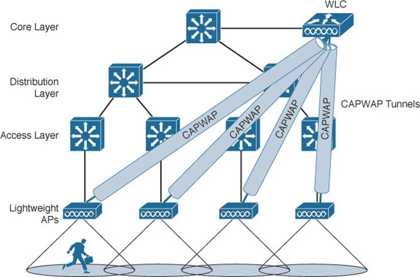
Figure 8-11 User Mobility in a Centralized Wireless Network
Locating the WLC centrally also affects the path that wireless data must take. For a wireless user to reach a wired network segment, the traffic is tunneled from the LAP to the WLC as shown in Figure 8-12. Notice that the tunnel extends the full expanse of the network hierarchy from the access layer to the core layer.
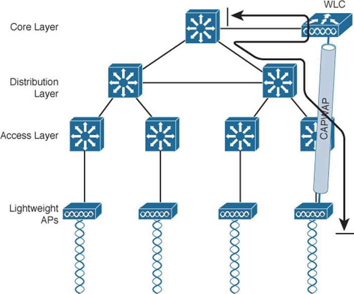
Figure 8-12 Traffic Path in a Centralized Wireless Network
The length of the tunnel path is not a great concern for wireless users trying to reach centralized resources. If the wireless users need to reach a local resource in the access layer or other wireless users, then the path becomes much more interesting. Recall that two wireless users associated with an autonomous AP can reach each other through the AP. In contrast, the path between two wireless users in a centralized network is shown in Figure 8-13. From Client A, the traffic must pass through the LAP, where it is encapsulated in the CAPWAP tunnel, then travel up to the core layer to reach the WLC, where it is unencapsulated, To go on to Client B, the process then reverses and the traffic goes back down through the tunnel to reach the AP and back out into the air.
![]()
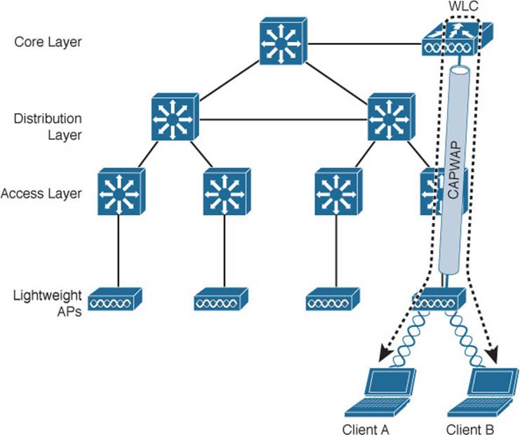
Figure 8-13 Traffic Path Between Wireless Clients in a Centralized Wireless Network
Tip
The length of the tunnel path can be a great concern for the LAPs, however. The round-trip time (RTT) between an LAP and a controller should be less than 100 ms so that wireless communication can be maintained in near real time. If the path has more latency than that, the LAPs may decide that the controller is not responding fast enough, causing them to disconnect and find another, more responsive controller.
Such “hairpin” paths can be rather inefficient because both ends of the split-MAC mechanism must be traversed in both directions. Now consider an enterprise that has some branch sites that are located some distance away from the main campus. LAPs can be deployed at the branch site too, joining to a centralized WLC back at headquarters. Wireless users at the branch site might need to access local file servers or printers, so their traffic paths must hairpin over the WAN link that ultimately connects to the WLC. The branch users become totally dependent on the WAN link—if the link goes down, the CAPWAP tunnel will fail. Once that happens, the users can be cut off from their local resources, too.
Tip
Cisco LAPs can remedy this situation by providing local access through the FlexConnect feature. The additional FlexConnect architecture is discussed later in this chapter.
Converged Wireless Network Architecture
As an alternative to the centralized wireless architecture, where WLCs are located near the core layer, the WLC function can be moved further down in the network hierarchy. Relocating the WLCs does two things:
![]() The WLC function is moved closer to the LAPs (and the wireless users).
The WLC function is moved closer to the LAPs (and the wireless users).
![]() The WLC function becomes distributed, rather than centralized.
The WLC function becomes distributed, rather than centralized.
The access layer turns out to be a convenient location for the WLCs. After all, wireless users ultimately connect to a WLC, which serves as a virtual access layer. Why not move the wireless access layer to coincide with the wired access layer? With all types of user access merged into one layer, it becomes much easier to do things like apply common access and security policies that affect all users. This is known as a converged wireless network architecture. To distinguish the two approaches, centralized controllers are known as WLCs, while converged controllers are known as Wireless Control Modules (WCMs).
Tip
As you prepare for the exam, remember the distinction between the centralized and converged architectures, with regard to the WLC and WCM functions. One other difference is that WLCs run the Cisco AireOS software, while WCMs are based on the Cisco IOS-XE software that runs on the Catalyst switches that host the WCMs.
As you might imagine, distributing the controller function into the access layer increases the number of controllers that are needed. One controller is needed per access switch stack or chassis. The idea is to push more controllers down closer to the users, which also reduces the number of APs and clients that connect to each one. How can this be accomplished? The Cisco Catalyst 3650, 3850, and 4500 (Supervisor 8-E only) product families are commonly used as access layer switches, plus they can offer converged-access WCM functions without needing any additional hardware.Table 8-2 lists the AP and client capacity of each switch platform.
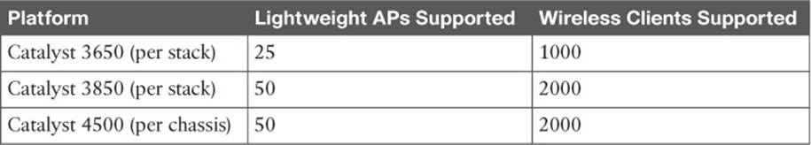
Table 8-2 Converged Access Switch Wireless Capacities
It might seem odd that the number of supported APs is rather low, when the physical port density of a switch is rather large. For instance, a Catalyst 3850 switch stack can consist of up to 432 wired ports (nine 48-port switches), but only 50 APs can be connected to the entire stack of switches. If you think of this from a wireless perspective, it makes more sense. Each AP is connected to the switch stack by a twisted-pair cable that is limited to a length of 100 meters. Therefore, all of the APs must be located within a 100 meter radius of the access switch. There are not too many AP cells that can physically fit into that area.
Figure 8-14 shows the basic converged wireless network architecture. Notice that each access switch performs both switching and WLC functions. Each AP connects to an access switch for network connectivity as well as split-MAC functionality, so the CAPWAP tunnel becomes really short—it exists only over the length of the cable connecting the AP! The arrow shows the length of the data path between the wireless and wired networks.
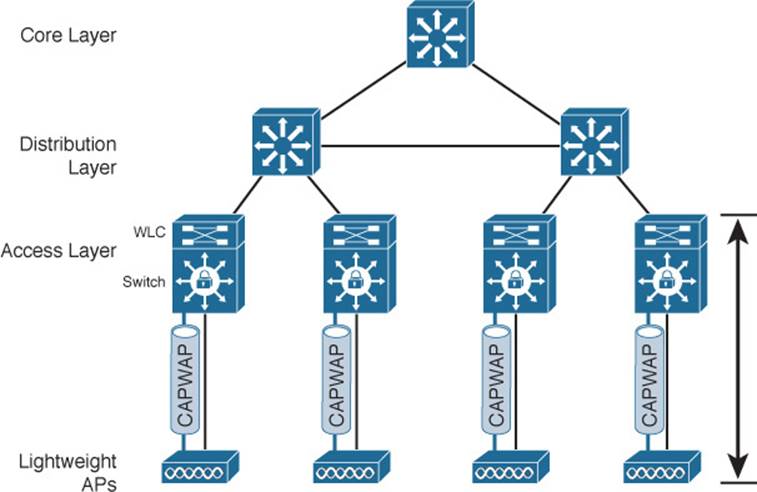
Figure 8-14 WLC Location in a Converged Wireless Network
One other advantage of the converged network architecture relates to wireless scalability. APs offering 802.11ac Wave 1 can use common 1-Gbps switch ports without limiting the throughput. Wave 2, however, has the potential to go well beyond 1 Gbps, which requires something more than a single 10/100/1000-Mbps switch port. Cisco offers proprietary Multigigabit Ethernet ports on several models in the Catalyst 3850 and 4500 families, where APs can connect over single cables. Multigigabit Ethernet can operate at speeds of 100 Mbps, 1 Gbps, 2.5 Gbps, and 5 Gbps over Cat5e cabling and up to 10 Gbps over Cat6a cabling speeds.
The converged model also solves some connectivity problems at branch sites by bringing a fully functional WLC onsite, within the access layer switch. With a local WLC, the APs can continue to operate without a dependency upon a WLC at the main site through a WAN connection.
How does the converged architecture affect user mobility? With more WLCs and fewer APs joined to each, you might expect that a mobile user will pass through more WLCs than in a centralized architecture. Figure 8-15 shows the basic network and AP layout. As a wireless user travels along, she could encounter many different WLCs as she roams from AP to AP. Therefore, some greater coordination must be used to support roaming in the converged model. Chapter 12, “Understanding Roaming,” discusses this in greater detail.
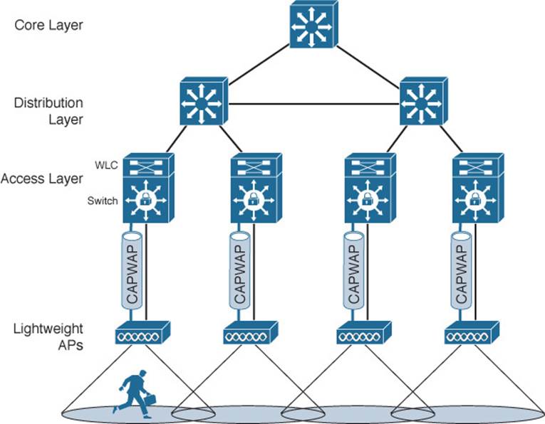
Figure 8-15 User Mobility in a Converged Wireless Network
If the CAPWAP tunnel is relatively short in a converged network, that must mean that wireless devices can reach each other more efficiently. Indeed, as Figure 8-16 shows, the traffic path from one user to another must pass through an LAP, the access switch (and WLC), and back down through the LAP. In contrast, traffic from a wireless user to a central resource such as a data center or the Internet travels through the CAPWAP tunnel, is unencapsulated at the access layer switch (and WLC), then travels normally up through the rest of the network layers.
![]()
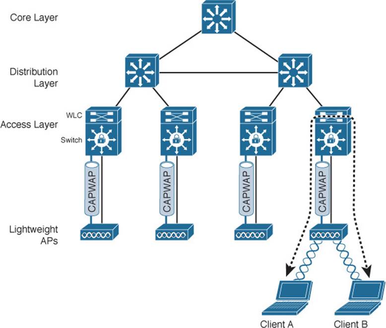
Figure 8-16 Traffic Path in a Converged Wireless Network
FlexConnect Wireless Network Architecture
In a switched campus infrastructure, the split-MAC traffic pattern is not a big problem because the WLC can be centrally located and bandwidth is plentiful. Suppose that the network grows to include some remote branch sites. LAPs are placed at the branch sites, but the only WLC is located back at the main campus. This scenario forces wireless traffic to traverse the CAPWAP tunnel between branch and main sites to reach centralized resources, as Figure 8-17 shows. Branch-site users might also need to access local nonwireless resources such as a file server and printers. In that case, the traffic path follows the CAPWAP tunnel to the WLC, then back through the tunnel to the branch site again. Such a path, as depicted in Figure 8-18, might not be efficient at all, especially when the bandwidth to the remote site is limited.
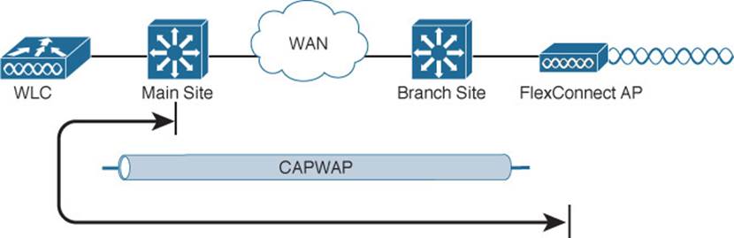
Figure 8-17 Split-MAC Architecture at a Branch Site
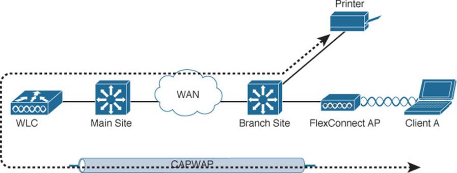
Figure 8-18 Traffic Path to Reach Nonwireless Resources in a Branch Site
To address the inefficiency, you can leverage the FlexConnect mode on the remote-site LAPs. Remote-site traffic that needs to traverse the CAPWAP data tunnel to reach the WLC will be transported as usual. However, wireless traffic that is destined for branch-site networks can stay within the branch site; the branch-site LAPs are able to locally switch the traffic without traversing the CAPWAP tunnel. Even if the remote-site link goes down, severing the CAPWAP tunnel completely, FlexConnect allows the LAP to keep switching traffic locally to maintain wireless connectivity inside the remote site, as illustrated in the scenario in Figure 8-19. A FlexConnect AP can operate in two modes: when it can reach the WLC, it operates in connected mode; when the path to the WLC is broken, the AP operates in standalone mode.
![]()
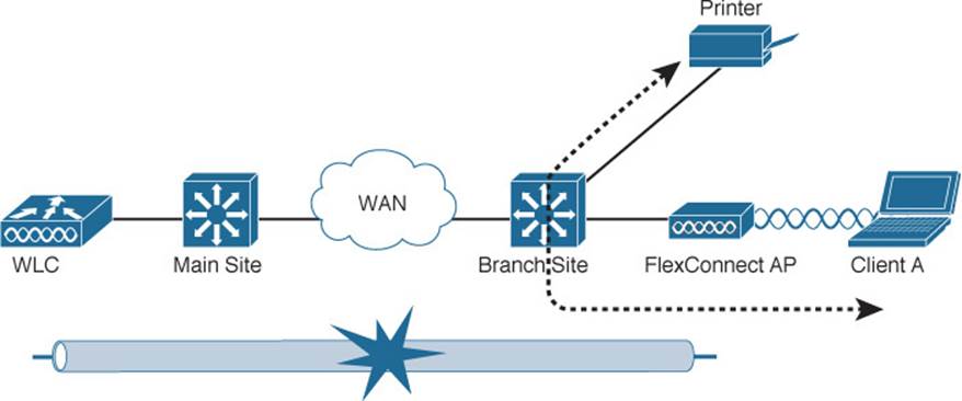
Figure 8-19 Traffic Path During FlexConnect Local Switching
Tip
FlexConnect was previously known as the Hybrid Remote Edge Access Point (H-REAP) feature. To maintain connectivity between the WLC and the branch-site LAP, the WAN link should have a round-trip latency less than 300 ms for normal data and less than 100 ms for data and voice traffic.
Cisco Wireless Network Building Blocks
A successful Cisco wireless network design can involve APs, WLCs, and a platform to manage them all. The following sections describe the Cisco hardware you can use as building blocks.
Cisco Wireless LAN Controllers
Cisco WLCs are available in many platforms, differing mainly in the form factor and the number of managed LAPs. The WLC platforms are listed in Table 8-3, arranged in ascending order by the maximum number of LAPs supported.
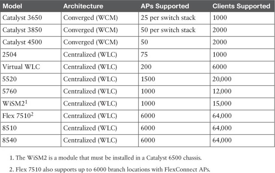
Table 8-3 Cisco WLC and WCM Platforms and Capabilities
Use Table 8-3 to become familiar with the entire spectrum of Cisco WLCs—not to memorize their specifications. Be aware of the relative AP capacity and architecture based on the model. Generally, the number of supported LAPs rises as the model number increases. Products that support a low number of LAPs are usually meant for small campus sites, while products that support 1000 or 6000 LAPs are flagship models that are meant for very large enterprises.
Many WLCs are standalone appliances, while others are integrated in Catalyst switch chassis. The Wireless Service Module 2 (WiSM2) is unique because it can be integrated into an existing Catalyst 6500 switch. Up to seven WiSM2 modules can live in a single switch chassis.
The virtual WLC (vWLC) is an interesting product because it consists of software only, running under a VMware Hypervisor. You might use it in a small enterprise or in a lab scenario. Because of its virtual nature, vWLC can coexist with other Cisco wireless management software on a single VMware platform. The vWLC cannot support any APs in local mode; all APs must be configured for FlexConnect instead.
Be aware that you can deploy several WLCs in a network, to handle a growing number of LAPs. In addition, multiple WLCs offer some redundancy so that LAPs can recover from a WLC failure. High availability and redundancy are covered in Chapter 11.
Cisco APs
Cisco Meraki APs are the building blocks for a cloud-based architecture. Table 8-4 lists the AP models with their basic capabilities.
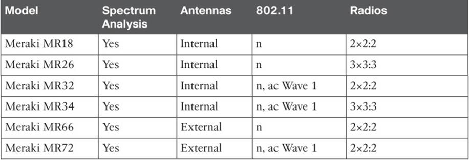
Table 8-4 Cisco Meraki Cloud-based Access Points and Their Capabilities
Cisco also offers a complete line of LAPs that are designed to connect to a WLC to offer fully functional wireless service. Table 8-5 lists many of the LAP models, along with their spectrum analysis capability, antenna location, and 802.11 radio support. All of the models except the 1850 can run an autonomous AP image instead of a lightweight AP image.
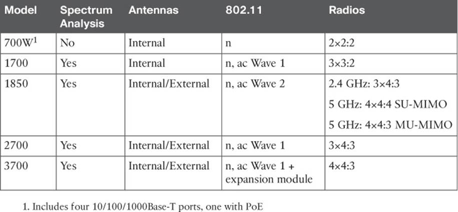
Table 8-5 Cisco Lightweight Access Points and Their Capabilities
The 1700, 2700, and 3700 models offer progressively larger feature sets and more robust radio chains. The 3700 is unique because it is modular and can provide “future-proof” upgrades. It can accept one of the following additional modules:
![]() Cisco Aironet Wireless Security Module—Performs channel scanning and intrusion protection with dedicated radios
Cisco Aironet Wireless Security Module—Performs channel scanning and intrusion protection with dedicated radios
![]() Cisco Universal Small Cell 5310 Module—Extends 3G cellular service to AP locations within buildings
Cisco Universal Small Cell 5310 Module—Extends 3G cellular service to AP locations within buildings
![]() Cisco Aironet 802.11ac Wave 2 Module—Available in the future; extends 802.11ac capabilities beyond Wave 1
Cisco Aironet 802.11ac Wave 2 Module—Available in the future; extends 802.11ac capabilities beyond Wave 1
The 1850 model is the first Cisco AP to offer fully integrated 802.11ac Wave 2. Notice how the number of radio chains changes to support 802.11n on 2.4 GHz and 802.11ac on 5 GHz. Wave 2 allows the AP to operate in multiuser multiple-input, multiple-output (MU-MIMO) mode.
With spectrum analysis capabilities, an AP can detect and identify sources of non-802.11 interference. In cooperation with a WLC, APs can also make adjustments to avoid the interference. When the AP and WLC are used in conjunction with Cisco Mobility Services Engine (MSE) and a Cisco wireless management platform, interferers can even be located on a map! This enables the wireless network to be self-healing, able to pinpoint and recover from external problems dynamically. Spectrum analysis through the Cisco CleanAir feature is discussed further in Chapter 19, “Dealing with Wireless Interference.”
The main difference between models pertains to 802.11ac support and MIMO operation, with a differing number of radios and spatial streams. Recall from Chapter 2, “RF Standards,” that a radio described as 2×3:2 has two transmitters, three receivers, and two spatial streams. As the number of radios and spatial streams increases, the AP is able to provide a greater throughput for its clients. Notice how the number of radios and spatial streams increase with 802.11ac Wave 1 and Wave 2 support.
Note
Tables 8-4 and 8-5 list only the APs that are used to provide a straightforward BSS. Cisco also offers the 1500 family of LAPs, which are used to build an outdoor wireless mesh network. Likewise, Cisco Meraki offers the MR66 and MR72 outdoor mesh APs. Mesh networks are outside the scope of this book and the CCNA Wireless exam.
Many Cisco APs can operate in either autonomous or lightweight mode, depending on which code image is loaded and run. From the WLC, you can also configure a lightweight AP to operate in one of the following special-purpose modes:
![]() Local—The default lightweight mode that offers one or more functioning BSSs on a specific channel. During times that it is not transmitting, the LAP will scan the other channels to measure the noise floor, measure interference, discover rogue devices, and match against intrusion detection system (IDS) events.
Local—The default lightweight mode that offers one or more functioning BSSs on a specific channel. During times that it is not transmitting, the LAP will scan the other channels to measure the noise floor, measure interference, discover rogue devices, and match against intrusion detection system (IDS) events.
![]() Monitor—The LAP does not transmit at all, but its receiver is enabled to act as a dedicated sensor. The LAP checks for IDS events, detects rogue access points, and determines the position of stations through location-based services (LBS).
Monitor—The LAP does not transmit at all, but its receiver is enabled to act as a dedicated sensor. The LAP checks for IDS events, detects rogue access points, and determines the position of stations through location-based services (LBS).
![]() FlexConnect—An LAP at a remote site can locally switch traffic between an SSID and a VLAN if its CAPWAP tunnel to the WLC is down and if it is configured to do so.
FlexConnect—An LAP at a remote site can locally switch traffic between an SSID and a VLAN if its CAPWAP tunnel to the WLC is down and if it is configured to do so.
![]() Sniffer—An LAP dedicates its radios to receiving 802.11 traffic from other sources, much like a sniffer or packet capture device. The captured traffic is then forwarded to a PC running network analyzer software such as Wildpackets OmniPeek or WireShark, where it can be analyzed further.
Sniffer—An LAP dedicates its radios to receiving 802.11 traffic from other sources, much like a sniffer or packet capture device. The captured traffic is then forwarded to a PC running network analyzer software such as Wildpackets OmniPeek or WireShark, where it can be analyzed further.
![]() Rogue detector—An LAP dedicates itself to detecting rogue devices by correlating MAC addresses heard on the wired network with those heard over the air. Rogue devices are those that appear on both networks.
Rogue detector—An LAP dedicates itself to detecting rogue devices by correlating MAC addresses heard on the wired network with those heard over the air. Rogue devices are those that appear on both networks.
![]() Bridge—An LAP becomes a dedicated bridge (point to point or point to multipoint) between two networks. Two LAPs in bridge mode can be used to link two locations separated by a distance. Multiple LAPs in bridge mode can form an indoor or outdoor mesh network.
Bridge—An LAP becomes a dedicated bridge (point to point or point to multipoint) between two networks. Two LAPs in bridge mode can be used to link two locations separated by a distance. Multiple LAPs in bridge mode can form an indoor or outdoor mesh network.
![]() Flex+Bridge—FlexConnect operation is enabled on a mesh AP.
Flex+Bridge—FlexConnect operation is enabled on a mesh AP.
![]() SE-Connect—The LAP dedicates its radios to spectrum analysis on all wireless channels. You can remotely connect a PC running software such as MetaGeek Chanalyzer or Cisco Spectrum Expert to the LAP to collect and analyze the spectrum analysis data to discover sources of interference.
SE-Connect—The LAP dedicates its radios to spectrum analysis on all wireless channels. You can remotely connect a PC running software such as MetaGeek Chanalyzer or Cisco Spectrum Expert to the LAP to collect and analyze the spectrum analysis data to discover sources of interference.
Exam Preparation Tasks
As mentioned in the section, “How to Use This Book,” in the Introduction, you have a couple of choices for exam preparation: the exercises here, Chapter 21, “Final Review,” and the exam simulation questions on the DVD.
Review All Key Topics
Review the most important topics in this chapter, noted with the Key Topic icon in the outer margin of the page. Table 8-6 lists a reference of these key topics and the page numbers on which each is found.
![]()
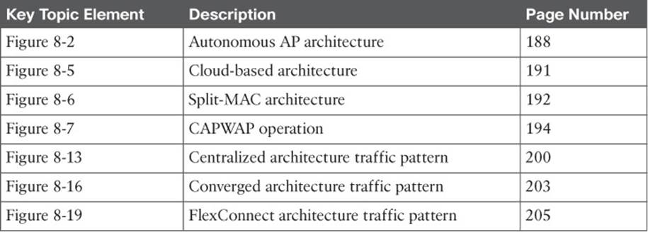
Table 8-6 Key Topics for Chapter 8
All materials on the site are licensed Creative Commons Attribution-Sharealike 3.0 Unported CC BY-SA 3.0 & GNU Free Documentation License (GFDL)
If you are the copyright holder of any material contained on our site and intend to remove it, please contact our site administrator for approval.
© 2016-2026 All site design rights belong to S.Y.A.