CCNP Routing and Switching ROUTE 300-101 Official Cert Guide (2015)
Part IV. Internet Connectivity
Chapter 12. Fundamentals of Internet Connectivity
This chapter covers the following subjects:
![]() Provider Assigned IPv4 Addresses: This section contrasts a couple of ways that an Internet service provider (ISP) can assign IPv4 addresses to their customers’ routers. Specifically, the ISP could give a customer an IP address to statically assign to his router, or the customer could use Dynamic Host Configuration Protocol (DHCP) to dynamically assign an IPv4 address from a pool of available addresses.
Provider Assigned IPv4 Addresses: This section contrasts a couple of ways that an Internet service provider (ISP) can assign IPv4 addresses to their customers’ routers. Specifically, the ISP could give a customer an IP address to statically assign to his router, or the customer could use Dynamic Host Configuration Protocol (DHCP) to dynamically assign an IPv4 address from a pool of available addresses.
![]() NAT: This section discusses how the Network Address Translation (NAT) service allows an enterprise network to use private IPv4 addresses (that is, RFC 1918 addresses) internally, and have those private IP addresses translated into one or more publicly routable IPv4 addresses.
NAT: This section discusses how the Network Address Translation (NAT) service allows an enterprise network to use private IPv4 addresses (that is, RFC 1918 addresses) internally, and have those private IP addresses translated into one or more publicly routable IPv4 addresses.
The movie Field of Dreams said it best, “If you build it, they will come.” That has happened with the Internet. Over the past couple of decades, Internet access speeds have gone up as prices have come down, resulting in an increasing dependence on the Internet. For example, companies with multiple locations frequently securely interconnect those locations by creating a Virtual Private Network (VPN) tunnel across the Internet. Cloud storage services allow computers to back up and synchronize files over the Internet. The Internet is increasingly being used for voice and video communication, not to mention its traditional web browsing and email uses.
With such a reliance on the Internet, most network designs need to include Internet connectivity. This module begins with a look at how a router connecting to an Internet service provider (ISP) obtains an IP address. One option is for the ISP to statically assign one or more publicly routable IP address(es) to a customer. Another approach is to use Dynamic Host Configuration Protocol (DHCP), which allows an ISP to dynamically assign IP addresses to customer routers.
If an enterprise network is primarily using IPv4 addresses, as opposed to IPv6 addresses, it probably uses Network Address Translation (NAT) when connecting to the Internet. The issue necessitating the use of NAT is the depletion of IPv4 addresses, as discussed in Chapter 3, “IPv6 Review and RIPng.” Because there are not enough IPv4 addresses to give every networked device in the world a unique IPv4 address, NAT allows networks to use private IP addresses (that is, IPv4 addresses defined by RFC 1918, which are not routable on the public Internet). Those internally used private IP addresses are then translated, using NAT, into one or more publicly routable IPv4 addresses. This chapter concludes with a discussion of NAT theory and configuration.
“Do I Know This Already?” Quiz
The “Do I Know This Already?” quiz allows you to assess whether you should read the entire chapter. If you miss no more than one of these seven self-assessment questions, you might want to move ahead to the “Exam Preparation Tasks” section. Table 12-1 lists the major headings in this chapter and the “Do I Know This Already?” quiz questions covering the material in those headings so that you can assess your knowledge of these specific areas. The answers to the “Do I Know This Already?” quiz appear in Appendix A.

Table 12-1 “Do I Know This Already?” Foundation Topics Section-to-Question Mapping
1. You are configuring a default route that should direct traffic for unknown networks out of interface Fa 0/0 to a next-hop IP address of 192.168.1.100. Which of the following commands should you use to configure the default route?
a. ip route 255.255.255.255 255.255.255.255 fa 0/0
b. ip route 255.255.255.255 255.255.255.255 192.168.1.100
c. ip route 0.0.0.0 0.0.0.0 fa 0/0
d. ip route 0.0.0.0 0.0.0.0 192.168.1.100
2. What interface configuration mode command instructs an interface to dynamically obtain its IP address from a DHCP server?
a. ip address 255.255.255.255
b. ip address dynamic
c. ip address dhcp
d. ip address bootp
3. Interface Fa 0/0 on your router has obtained an IP address through DHCP. You notice that in addition to an IP address assigned to interface Fa 0/0, your router now has a default static route configured. What command can you issue to prevent a router from automatically installing a default static route based on default gateway information learned through DHCP?
a. no ip dhcp client request router
b. ip dhcp suppress gateway
c. ip dhcp route local
d. no ip dhcp server response router
4. Interface Fa 0/0 on your router has obtained an IP address through DHCP. You notice that in addition to an IP address assigned to interface Fa 0/0, your router now has a default static route configured. What is the administrative distance (AD) of that route?
a. 0
b. 1
c. 254
d. 255
5. What type of Network Address Translation (NAT) allows a collection of inside local addresses to share a single inside global address, for use when communicating on the Internet?
a. DNAT
b. SNAT
c. PAT
d. MAT
6. A laptop inside your network has an IP address of 10.1.1.241. Using NAT, a router translates the 10.1.1.241 private IP address into 198.51.100.54, a public IP address, as the laptop is connecting to a web server on the Internet. The web server has an IP address of 203.0.113.10. What type of address is 10.1.1.241 in this scenario?
a. Outside global
b. Inside local
c. Inside global
d. Outside local
7. A laptop inside your network has an IP address of 10.1.1.241. Using NAT, a router translates the 10.1.1.241 private IP address into 198.51.100.54, a public IP address, as the laptop is connecting to a web server on the Internet. The web server has an IP address of 203.0.113.10. What type of address is 203.0.113.10 in this scenario?
a. Outside global
b. Inside local
c. Inside global
d. Outside local
Foundation Topics
Provider-Assigned IPv4 Addresses
ISPs have collections of publicly routable IPv4 addresses that they can distribute to their customers, thus allowing devices in the customer networks to communicate over the Internet. The IPv4 address assignments to customers could be either static assignments or dynamic assignments.
Static assignments might be useful to customers that have servers needing to be accessed from the Internet. For example, a company might have a web server as part of its network. If there is a static IP address assignment for that server, a Domain Name System (DNS) name could be associated with that IP address, allowing users on the Internet to access the web server by specifying the DNS name of the server (as opposed to its IP address) in their web browser.
However, if a company does not have any on-site servers needing to be accessed from the public Internet, it might not need a static IP address. In such situations, an ISP might dynamically assign one or more IP addresses to the company.
Note
If an ISP does not offer static IP address assignment to its customers, or if there is an extra charge associated with a static IP address, the customers might be able to use Dynamic DNS (DDNS), which dynamically updates DNS records to reflect current IP address assignments.
Static IP Address Assignment
Configuring an Internet-facing router with a statically assigned IP address involves two configuration steps:

Step 1. Assign an IP address to the router interface connecting to the ISP, using the ip address ip_address subnet_mask command, in interface configuration mode.
Step 2. Configure a default route pointing to the ISP, with the ip route 0.0.0.0 0.0.0.0 ip_address_of_isp_router command, in global configuration mode.
Note
Even though a default route can reference an egress router interface, rather than a next-hop IP address, specifying the next-hop IP address is considered a best practice. This is because, if you specify an Ethernet interface as the egress interface in a default route command, the router might generate an excessive number of ARP requests, resulting in poor router performance.
To illustrate the configuration of an Internet-facing router with a static IP address, consider Figure 12-1 and Example 12-1.
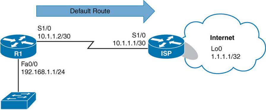
Figure 12-1 Topology with Static IP Address Assignment
Example 12-1 Static IP Address and Default Route Configuration
R1# conf term
Enter configuration commands, one per line. End with CNTL/Z.
R1(config)# int s 1/0
R1(config-if)# ip address 10.1.1.2 255.255.255.252
R1(config-if)# no shutdown
R1(config-if)# exit
R1(config)# ip route 0.0.0.0 0.0.0.0 10.1.1.1
R1(config)# end
R1# show ip route
Codes: L - local, C - connected, S - static, R - RIP, M - mobile, B - BGP
D - EIGRP, EX - EIGRP external, O - OSPF, IA - OSPF inter area
N1 - OSPF NSSA external type 1, N2 - OSPF NSSA external type 2
E1 - OSPF external type 1, E2 - OSPF external type 2
i - IS-IS, su - IS-IS summary, L1 - IS-IS level-1, L2 - IS-IS level-2
ia - IS-IS inter area, * - candidate default, U - per-user static route
o - ODR, P - periodic downloaded static route, H - NHRP, l - LISP
+ - replicated route, % - next hop override
Gateway of last resort is 10.1.1.1 to network 0.0.0.0
S* 0.0.0.0/0 [1/0] via 10.1.1.1
10.0.0.0/8 is variably subnetted, 2 subnets, 2 masks
C 10.1.1.0/30 is directly connected, Serial1/0
L 10.1.1.2/32 is directly connected, Serial1/0
192.168.1.0/24 is variably subnetted, 2 subnets, 2 masks
C 192.168.1.0/24 is directly connected, FastEthernet0/0
L 192.168.1.1/32 is directly connected, FastEthernet0/0
R1# ping 1.1.1.1
Type escape sequence to abort.
Sending 5, 100-byte ICMP Echos to 1.1.1.1, timeout is 2 seconds:
!!!!!
Success rate is 100 percent (5/5), round-trip min/avg/max = 36/37/44 ms
R1#
In Example 12-1, Router R1 is an Internet-facing router located at a customer site. The ISP assigned the customer a static IP address of 10.1.1.2 /30. The configuration on Router R1 begins by configuring the IP address of the Serial 1/0 interface with the ip address 10.1.1.2 255.255.255.252command, followed by administratively bringing up the interface (if it were shut down) with the no shutdown command. Next, in global configuration mode, a default static route is configured, using the ip route 0.0.0.0 0.0.0.0 10.1.1.1 command, to point to a next-hop address of 10.1.1.1, which is the IP address of the ISP router interface connecting to the customer. Then, the show ip route command was issued to verify the creation of the static route. Finally, a ping 1.1.1.1 command was issued to see whether Router R1 had connectivity to an address residing in the Internet, and the ping was successful.
Dynamic IP Address Assignment
Dynamic IP address assignment, which is commonly used in residential and small-business environments, allows an Internet-facing interface on a customer router to learn IP address information from an ISP’s Dynamic Host Configuration Protocol (DHCP) server.
Interestingly, there is no need to configure a static default route (as was configured in Example 12-1), because the DHCP server informs the customer router of an IP address of the default gateway (that is, the ISP router). Therefore, the customer router needs only a single command, issued in interface configuration mode: ip address dhcp (in addition to administratively bringing up the interface, if it were shut down).
To illustrate the configuration and verification of dynamic IP address assignment, consider Figure 12-2 and Example 12-2.
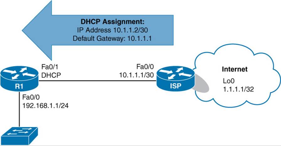
Figure 12-2 Topology with Dynamic IP Address Assignment
Example 12-2 Dynamic IP Address Configuration
R1# conf term
R1(config)# interface fa 0/1
R1(config-if)# ip address dhcp
R1(config-if)# end
R1#
*Jun 3 10:56:42.111: %DHCP-6-ADDRESS_ASSIGN: Interface FastEthernet0/1 assigned
DHCP address
10.1.1.2, mask 255.255.255.252, hostname R1
R1# show ip interface brief
Interface IP-Address OK? Method Status Protocol
FastEthernet0/0 192.168.1.1 YES NVRAM up up
FastEthernet0/1 10.1.1.2 YES DHCP up up
Serial1/0 unassigned YES NVRAM administratively down down
Serial1/1 unassigned YES NVRAM administratively down down
Serial1/2 unassigned YES NVRAM administratively down down
Serial1/3 unassigned YES NVRAM administratively down down
R1# show ip route
Codes: L - local, C - connected, S - static, R - RIP, M - mobile, B - BGP
D - EIGRP, EX - EIGRP external, O - OSPF, IA - OSPF inter area
N1 - OSPF NSSA external type 1, N2 - OSPF NSSA external type 2
E1 - OSPF external type 1, E2 - OSPF external type 2
i - IS-IS, su - IS-IS summary, L1 - IS-IS level-1, L2 - IS-IS level-2
ia - IS-IS inter area, * - candidate default, U - per-user static route
o - ODR, P - periodic downloaded static route, H - NHRP, l - LISP
+ - replicated route, % - next hop override
Gateway of last resort is 10.1.1.1 to network 0.0.0.0
S* 0.0.0.0/0 [254/0] via 10.1.1.1
10.0.0.0/8 is variably subnetted, 2 subnets, 2 masks
C 10.1.1.0/30 is directly connected, FastEthernet0/1
L 10.1.1.2/32 is directly connected, FastEthernet0/1
192.168.1.0/24 is variably subnetted, 2 subnets, 2 masks
C 192.168.1.0/24 is directly connected, FastEthernet0/0
L 192.168.1.1/32 is directly connected, FastEthernet0/0
R1# ping 1.1.1.1
Type escape sequence to abort.
Sending 5, 100-byte ICMP Echos to 1.1.1.1, timeout is 2 seconds:
!!!!!
Success rate is 100 percent (5/5), round-trip min/avg/max = 24/30/56 ms
R1#
In Example 12-2, the ip address dhcp command is issued for interface Fa 0/1, which instructs the interface to obtain IP address information through DHCP. A syslog message is then displayed, stating that an IP address of 10.1.1.2, with a subnet mask of 255.255.255.252, has been assigned to Fa 0/1.
Output from the show ip interface brief command indicates that the Fa 0/1 interface obtained an IP address of 10.1.1.2 through DHCP. The show ip route command output shows a default static route pointing to a next-hop IP address of 10.1.1.1, which was learned through DHCP. Note that the administrative distance for the route is 254. This high value makes the route a floating static route, meaning that the route will only be used if a default route is not already known to another routing process (with a lower administrative distance). Finally, the ping 1.1.1.1 output verifies that Router R1 has connectivity to an address on the Internet.
Note
You can prevent a router from installing a static default route, based on the default gateway information learned from a DHCP server, by issuing the no ip dhcp client request router command in interface configuration mode.
NAT
While IP addresses are routable through the public Internet, other IP addresses (as defined by RFC 1918) are considered private and are intended for use within an organization. Network Address Translation (NAT) allows private IP addresses to be translated into Internet-routable IP addresses (that is, public IP addresses). This section examines the operation of basic NAT and a variant called Port Address Translation (PAT). Then, this section reviews a collection of NAT design considerations and a fairly recent enhancement to NAT configuration, called NAT Virtual Interface (NVI).
Basic NAT
Consider Figure 12-3, which shows a basic NAT topology.
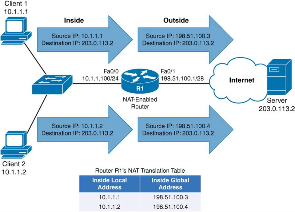
Figure 12-3 Basic NAT Topology
In the topology, two clients, with private IP addresses of 10.1.1.1 and 10.1.1.2, want to communicate with a web server on the public Internet. The server’s IP address is 203.0.113.2. Router R1 is configured for NAT. As an example, Router R1 takes packets coming from 10.1.1.1 destined for 203.0.113.2 and changes the source IP address in the packets’ headers to 198.51.100.3. When the server at IP address 203.0.113.2 receives traffic from the client, the server’s return traffic is sent to a destination address of 198.51.100.3. When Router R1 receives traffic from the outside network destined for 198.51.100.3, the router translates the destination IP address to 10.1.1.1 and forwards the traffic to the inside network where Client 1 receives the traffic. Similarly, Client 2’s IP address of 10.1.1.2 is translated into an IP address of 198.51.100.4.
Table 12-2 introduces you to the terminology used when describing the various IP addresses involved in a translation.
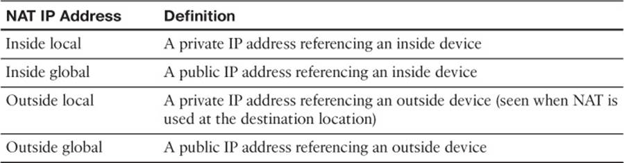
Table 12-2 Names of NAT IP Addresses
As a memory aid, remember that inside always refers to an inside device, while outside always refers to an outside device. Also, think of the word local being similar to the Spanish word loco, meaning crazy. That is what a local address could be considered. It is a crazy, made-up address (that is, a private IP address that is not routable on the Internet). Finally, let the g in global remind you of the g in good, because a global address is a good IP address (that is, routable on the Internet).
Based on these definitions, Table 12-3 categorizes the IP addresses previously shown in Figure 12-3.
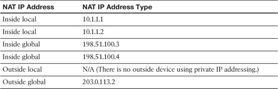
Table 12-3 Classifying the NAT IP Addresses Shown in Figure 12-3
Whether an inside local address is randomly assigned an inside global address from a pool of available addresses or is assigned an address from a static configuration determines the type of NAT you are using. These two approaches to NAT are called Dynamic NAT (DNAT) and Static NAT (SNAT):
![]() DNAT: Dynamic NAT occurs when inside local addresses are automatically assigned an inside global address from a pool of available addresses.
DNAT: Dynamic NAT occurs when inside local addresses are automatically assigned an inside global address from a pool of available addresses.
![]() SNAT: Sometimes you might want to statically configure the inside global address assigned to a specific device inside your network. For example, you might have an email server inside your company, and you want other email servers on the Internet to send email messages to your server. Those email servers on the Internet need to point to a specific IP address, not one that was randomly picked from a pool of available IP addresses. In such a case, you could statically configure the mapping of an inside local address (that is, the IP address of your internal email server) to an inside global address (that is, the IP address to which email servers on the Internet will send email for your company). This approach to NAT is referred to as static NAT (SNAT).
SNAT: Sometimes you might want to statically configure the inside global address assigned to a specific device inside your network. For example, you might have an email server inside your company, and you want other email servers on the Internet to send email messages to your server. Those email servers on the Internet need to point to a specific IP address, not one that was randomly picked from a pool of available IP addresses. In such a case, you could statically configure the mapping of an inside local address (that is, the IP address of your internal email server) to an inside global address (that is, the IP address to which email servers on the Internet will send email for your company). This approach to NAT is referred to as static NAT (SNAT).
Dynamic NAT Configuration and Verification
You can configure dynamic NAT (where inside local addresses are translated into an inside global address by dynamically being assigned an address from a pool of available addresses) with the following steps:
Step 1. Create an access control list (ACL) to match the inside local addresses to be translated. While you could use either a named or numbered ACL and either a standard or an extended ACL, the command to create a standard numbered ACL (in global configuration mode) is access-list {1 – 99} permit network_address wildcard_mask.
Step 2. Define a NAT pool containing the available inside global addresses by issuing the ip nat pool pool_name starting_ip ending_ip netmask subnet_mask command in global configuration mode.
Step 3. Specify that an interface is an inside interface with the ip nat inside command (in interface configuration mode).
Step 4. Specify that an interface is an outside interface, with the ip nat outside command (in interface configuration mode).
Step 5. Associate the ACL (identifying the inside local addresses) with the NAT pool (identifying the inside global addresses) using the ip nat inside source list acl pool nat_pool command (in global configuration mode).
Example 12-3, based on the topology illustrated in Figure 12-4, shows a dynamic NAT configuration example.
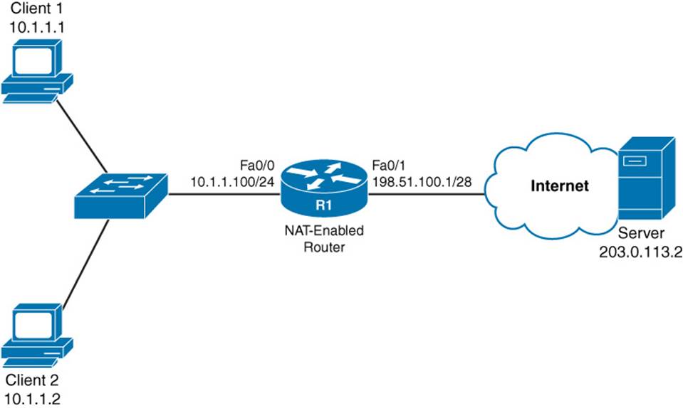
Figure 12-4 NAT Topology
Example 12-3 Dynamic NAT Configuration
R1# show run
... OUTPUT OMITTED ...
interface FastEthernet0/0
ip address 10.1.1.100 255.255.255.0
ip nat inside
!
interface FastEthernet0/1
ip address 198.51.100.1 255.255.255.240
ip nat outside
... OUTPUT OMITTED ...
ip nat pool ISP-POOL 198.51.100.3 198.51.100.14 netmask 255.255.255.240
ip nat inside source list 1 pool ISP-POOL
!
access-list 1 permit 10.1.1.0 0.0.0.255
R1# show ip nat translations
Pro Inside global Inside local Outside local Outside global
icmp 198.51.100.3:6 10.1.1.1:6 203.0.113.2:6 203.0.113.2:6
--- 198.51.100.3 10.1.1.1 --- ---
icmp 198.51.100.4:1 10.1.1.2:1 203.0.113.2:1 203.0.113.2:1
--- 198.51.100.4 10.1.1.2 --- ---
In Example 12-3, the Fa 0/0 interface is designated as an inside interface with the ip nat inside command. Similarly, the Fa 0/1 interface is designated as an outside interface with the ip nat outside command.
The inside local addresses are identified with the access-list 1 permit 10.1.1.0 0.0.0.255 command, and a NAT pool containing a range of inside global addresses is specified with the ip nat pool ISP-POOL 198.51.100.3 198.51.100.14 netmask 255.255.255.240 command. The ACL specifying the inside local addresses and the NAT pool specifying the inside global addresses are then associated with one another using the ip nat inside source list 1 pool ISP-POOL command.
Output from the show ip nat translations command verifies that Router R1 is indeed performing NAT translations. The output also shows the sessions that Client 1 and Client 2 have with the Server, and the corresponding IP addresses being used.
Note
In Example 12-3, the Outside local column contains the server’s IP address of 203.0.113.2, which is the same IP address shown in the Outside global column. The reason these IP addresses are the same is that NAT is not being performed at the server’s location. Because there is no private IP address representing the server, you can ignore the Outside local column for this topology (and in most NAT topologies).
Static NAT Configuration and Verification
Unlike a dynamic NAT configuration, a static NAT configuration requires no ACL or NAT pool. Instead, a series of ip nat inside source static inside_local_address inside_global_address commands can be issued (in global configuration mode) to instruct NAT how to perform its translations. The steps to perform a static NAT configuration are as follows:
Step 1. Create one or more inside local address to inside global address mappings with the ip nat inside source static inside_local_address inside_global_address command in global configuration mode.
Step 2. Specify that an interface is an inside interface with the ip nat inside command (in interface configuration mode).
Step 3. Specify that an interface is an outside interface with the ip nat outside command (in interface configuration mode).
Example 12-4 shows a static NAT configuration performed on Router R1 from the topology in Figure 12-4.
Example 12-4 Static NAT Configuration
R1# show run
... OUTPUT OMITTED ...
interface FastEthernet0/0
ip address 10.1.1.100 255.255.255.0
ip nat inside
!
interface FastEthernet0/1
ip address 198.51.100.1 255.255.255.240
ip nat outside
... OUTPUT OMITTED ...
ip nat inside source static 10.1.1.1 198.51.100.3
ip nat inside source static 10.1.1.2 198.51.100.4
R1# show ip nat translations
Pro Inside global Inside local Outside local Outside global
--- 198.51.100.3 10.1.1.1 --- ---
--- 198.51.100.4 10.1.1.2 --- ---
As you saw in Example 12-3, in Example 12-4, the Fa 0/0 interface is designated as an inside interface with the ip nat inside command. Also, the Fa 0/1 interface is designated as an outside interface with the ip nat outside command.
The ip nat inside source static 10.1.1.1 198.51.100.3 command instructs the router to translate an inside local address of 10.1.1.1 into an inside global address of 198.51.100.3. Similarly, the ip nat inside source static 10.1.1.2 198.51.100.4 command instructs the router to translate an inside local address of 10.1.1.2 into an inside global address of 198.51.100.4.
Also, notice that the output of the show ip nat translations command only shows the inside local and inside global addresses specified in the static assignments. There is no dynamic session information to show information about active sessions (such as an outside global address).
PAT
A challenge with basic NAT, however, is that there is a one-to-one mapping of inside local addresses to inside global addresses, meaning that a company would need as many publicly routable IP addresses as it had internal devices needing IP addresses. This does not scale well, because a service provider will often only provide a customer with a single IP address or a small block of IP addresses.
Fortunately, Cisco routers support Port Address Translation (PAT), which allows multiple inside local addresses to share a single inside global address (that is, a single publicly routable IP address). Recall that when a client sends an IP packet, not only does that packet have a source and a destination IP address, but it also has a source and destination port number. PAT leverages these port numbers to keep track of separate communication flows.
As an example, consider Figure 12-5. Unlike the example shown in Figure 12-3, in which each inside local address was translated to its own inside global address, the example shown in Figure 12-5 only has one inside global address (198.51.100.1). This single inside global address is shared among all the devices inside a network. The different communication flows are kept separate in Router R1’s NAT translation table by considering port numbers.
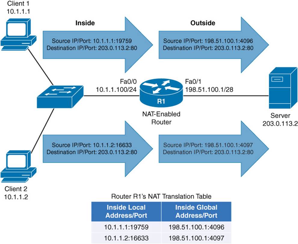
Figure 12-5 PAT Topology
When Client 1 (with an IP address of 10.1.1.1) sends a packet to the web server (with an IP address of 203.0.113.2), the client’s ephemeral port number (that is, its source port, which is greater than 1023) is 19759. Router R1 notes that port number, and translates the inside local address of 10.1.1.1 with a port number of 19759 to an inside global address of 198.51.100.1 with a port number of 4096.
When Client 2 sends a packet to the same web server, its inside local address of 10.1.1.2 with a port number of 16633 is translated into an outside local address of 198.51.100.1 with a port number of 4097.
Notice that both Client 1 and Client 2 had their inside local addresses translated into the same inside global address of 198.51.100.1. Therefore, when the web server is sending packets back to Client 1 and Client 2, those packets are destined for the same IP address (that is, 198.51.100.1). However, when Router R1 receives those packets, it knows to which client each packet should be forwarded, based on the destination port number. For example, if a packet from the web server (203.0.113.2) arrived at Router R1 with a destination IP address of 198.51.100.1 and a destination port number of 4097, Router R1 would translate the destination IP address to 10.1.1.2 with a port number of 16633, and they forward the packet off to Client 2. The steps to configure PAT are as follows:
Step 1. Create an access control list (ACL) to match the inside local addresses to be translated. While you could use either a named or numbered ACL and either a standard or an extended ACL, the command to create a standard numbered ACL (in global configuration mode) is access-list {1 - 99} permit network_address wildcard_mask.
Step 2. Specify that an interface is an inside interface with the ip nat inside command (in interface configuration mode).
Step 3. Specify that an interface is an outside interface with the ip nat outside command (in interface configuration mode).
Step 4. Associate the ACL (identifying the inside local addresses) with the router’s outside interface, and enable overloading with the ip nat inside source list acl interface outside_interface overload command (in global configuration mode).
Example 12-5 shows a sample PAT configuration, based on the topology shown in Figure 12-5.
Example 12-5 PAT Configuration
R1# show run
... OUTPUT OMITTED ...
interface FastEthernet0/0
ip address 10.1.1.100 255.255.255.0
ip nat inside
!
interface FastEthernet0/1
ip address 198.51.100.1 255.255.255.240
ip nat outside
... OUTPUT OMITTED ...
ip nat inside source list 1 interface FastEthernet0/1 overload
!
access-list 1 permit 10.1.1.0 0.0.0.255
R1# show ip nat translations
Pro Inside global Inside local Outside local Outside global
tcp 198.51.100.1:4096 10.1.1.1:19759 203.0.113.2:80 203.0.113.2:80
tcp 198.51.100.1:4097 10.1.1.2:16633 203.0.113.2:80 203.0.113.2:80
As in Examples 12-3 and 12-4, in Example 12-5, the Fa 0/0 interface is designated as an inside interface with the ip nat inside command. Also, the Fa 0/1 interface is designated as an outside interface with the ip nat outside command.
The access-list 1 permit 10.1.1.0 0.0.0.255 command is used to identify inside local addresses. Then, the ip nat inside source list 1 interface FastEthernet0/1 overload command is used to associate the ACL defining the inside local addresses with the IP address of the Fa 0/1 interface. Theoverload parameter given in the command enables the PAT feature, allowing multiple inside local addresses to share an inside global address (specifically, the IP address of the Fa 0/1 interface).
Output from the show ip nat translations command shows that the same inside global address (the IP address of the Fa 0/1 interface) is being used by both Client 1 (10.1.1.1) and Client 2 (10.1.1.2). However, PAT is able to distinguish between these clients, because they have unique port numbers (4096 for Client 1 and 4097 for Client 2).
NAT Design Considerations
While NAT has done much to extend the life of IPv4, it does have limitations you should consider in your design. Consider the following:
![]() Applications requiring end-to-end connectivity, where source and destination IP addresses are not modified at any point on the data path, could fail because of NAT’s modification of source and destination IP addresses.
Applications requiring end-to-end connectivity, where source and destination IP addresses are not modified at any point on the data path, could fail because of NAT’s modification of source and destination IP addresses.
![]() NAT might have compatibility issues with IPsec, because IPsec performs message integrity checks, which could fail because of NAT’s manipulation of header contents.
NAT might have compatibility issues with IPsec, because IPsec performs message integrity checks, which could fail because of NAT’s manipulation of header contents.
![]() In a Public Key Infrastructure (PKI) environment, digital certificates can be used for authentication and encryption. However, the digital signature on a digital certificate could be incorrect, based on a device’s IP being changed by NAT.
In a Public Key Infrastructure (PKI) environment, digital certificates can be used for authentication and encryption. However, the digital signature on a digital certificate could be incorrect, based on a device’s IP being changed by NAT.
NVI
Cisco IOS Release 12.3(14)T introduced a feature called NAT Virtual Interface (NVI), which allows you to do a NAT configuration without the need to specify an interface as being an inside or an outside interface. Specifically, instead of issuing the ip nat inside or ip nat outside command in interface configuration mode, you can issue the ip nat enable command. Not only does this feature make configuration easier, but it also allows traffic to flow between two interfaces that would both be considered inside interfaces, from a classic NAT perspective.
Note
Not all platforms and Cisco IOS versions since Cisco IOS Release 12.3(14)T support the NAT Virtual Interface feature. Therefore, the ip nat enable command might not be accepted on your device, even though you are running Cisco IOS Release 12.3(14)T or later.
This feature is made possible by performing an additional routing operation. To better understand this change, consider how classic NAT operated. It would make a routing decision prior to performing the address translation. However, an NVI makes an initial routing decision, then performs address translation, and finally performs another routing decision (based on the translated addresses).
Example 12-6 illustrates an NVI configuration, based on the Figure 12-4 topology.
Example 12-6 NVI Configuration
R1# show run
... OUTPUT OMITTED ...
interface FastEthernet0/0
ip address 10.1.1.100 255.255.255.0
ip nat enable
!
interface FastEthernet0/1
ip address 198.51.100.1 255.255.255.240
ip nat enable
... OUTPUT OMITTED ...
ip nat inside source list 1 interface FastEthernet0/1 overload
!
access-list 1 permit 10.1.1.0 0.0.0.255
The only difference in the NVI configuration shown in Example 12-6 and the PAT configuration shown in Example 12-5 is the use of the ip nat enable command (in global configuration mode), as opposed to either the ip nat inside or ip nat outside command.
Note
The NAT Virtual Interface feature can be used with a Dynamic NAT configuration or a PAT configuration, but it is not supported with a Static NAT configuration.
Exam Preparation Tasks
Planning Practice
The CCNP ROUTE exam expects test takers to review design documents, create implementation plans, and create verification plans. This section provides some exercises that can help you to take a step back from the minute details of the topics in this chapter so that you can think about the same technical topics from the planning perspective.
For each planning practice table, simply complete the table. Note that any numbers in parentheses represent the number of options listed for each item in the solutions in Appendix F, “Completed Planning Practice Tables.”
Design Review Table
Table 12-4 lists several design goals related to this chapter. If these design goals were listed in a design document, and you had to take that document and develop an implementation plan, what implementation options come to mind? For any configuration items, a general description can be used, without concern about the specific parameters.
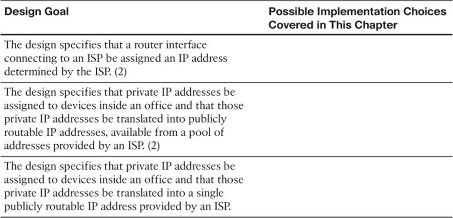
Table 12-4 Design Review
Implementation Plan Peer Review Table
Table 12-5 shows a list of questions that others might ask, or that you might think about, during a peer review of another network engineer’s implementation plan. Complete the table by answering the questions.
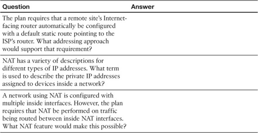
Table 12-5 Notable Questions from This Chapter to Consider During an Implementation Plan Peer Review
Create an Implementation Plan Table
To practice skills useful when creating your own OSPF implementation plan, list in Table 12-6 configuration commands related to the configuration of the following features. You might want to record your answers outside the book, and set a goal to complete this table (and others like it) from memory during your final reviews before taking the exam.
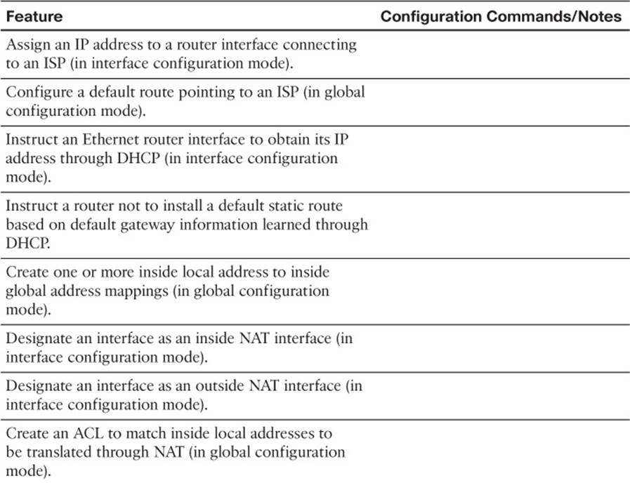
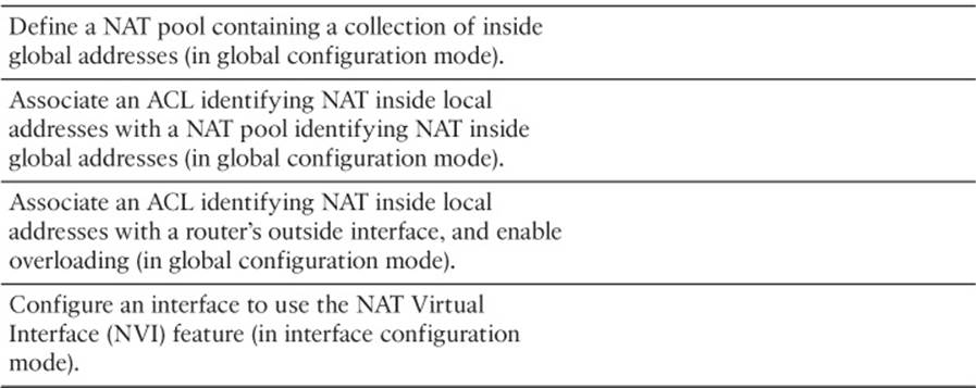
Table 12-6 Implementation Plan Configuration Memory Drill
Choose Commands for a Verification Plan Table
To practice skills useful when creating your own OSPF verification plan, list in Table 12-7 all commands that supply the requested information. You might want to record your answers outside the book, and set a goal to complete this table (and others like it) from memory during your final reviews before taking the exam.
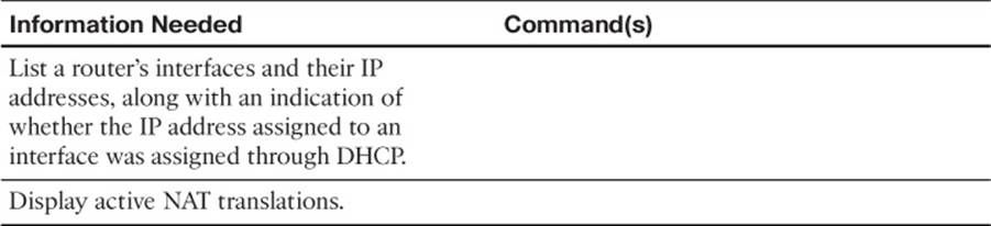
Table 12-7 Verification Plan Memory Drill
Review All the Key Topics
Review the most important topics from inside the chapter, noted with the Key Topic icon in the outer margin of the page. Table 12-8 lists a reference of these key topics and the page numbers on which each is found.
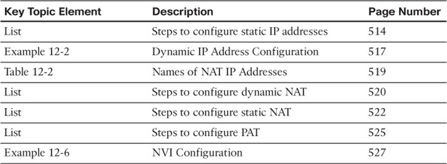
Table 12-8 Key Topics for Chapter 12
Complete the Tables and Lists from Memory
Print a copy of Appendix D, “Memory Tables,” (found on the CD) or at least the section for this chapter, and complete the tables and lists from memory. Appendix E, “Memory Tables Answer Key,” also on the CD, includes completed tables and lists to check your work.
Define Key Terms
Define the following key terms from this chapter, and check your answers in the glossary.
NAT
DNAT
SNAT
PAT
NVI
All materials on the site are licensed Creative Commons Attribution-Sharealike 3.0 Unported CC BY-SA 3.0 & GNU Free Documentation License (GFDL)
If you are the copyright holder of any material contained on our site and intend to remove it, please contact our site administrator for approval.
© 2016-2026 All site design rights belong to S.Y.A.