CCNP Routing and Switching ROUTE 300-101 Official Cert Guide (2015)
Part I. Fundamental Routing Concepts
Chapter 2. Remote Site Connectivity
This chapter covers the following subjects:
![]() Remote Connectivity Overview: This section explains why VPNs are often a preferred method of remotely connecting to sites and identifies a collection of available VPN technologies.
Remote Connectivity Overview: This section explains why VPNs are often a preferred method of remotely connecting to sites and identifies a collection of available VPN technologies.
![]() MPLS VPN: This section contrasts Layer 2 MPLS VPNs and Layer 3 MPLS VPNs.
MPLS VPN: This section contrasts Layer 2 MPLS VPNs and Layer 3 MPLS VPNs.
![]() GRE: This section describes a GRE tunnel and demonstrates GRE tunnel configuration and verification.
GRE: This section describes a GRE tunnel and demonstrates GRE tunnel configuration and verification.
![]() DMVPN: This section discusses how DMVPNs can dynamically bring up connections between specific spokes in a hub-and-spoke VPN topology.
DMVPN: This section discusses how DMVPNs can dynamically bring up connections between specific spokes in a hub-and-spoke VPN topology.
![]() Multipoint GRE: This section explains how a single GRE interface can have connections to multiple GRE peers.
Multipoint GRE: This section explains how a single GRE interface can have connections to multiple GRE peers.
![]() NHRP: This section explains how NHRP can discover next-hop IP addresses in networks using IP tunneling.
NHRP: This section explains how NHRP can discover next-hop IP addresses in networks using IP tunneling.
![]() IPsec: This section explores how IPsec can be used to secure a VPN connection.
IPsec: This section explores how IPsec can be used to secure a VPN connection.
Traditional wide-area network (WAN) connections used technologies such as dedicated leased lines and permanent virtual circuits (PVC) defined in frame switching (for example, Frame Relay) and cell switching (for example, ATM) networks. As an example, if a company opened a remote sales office, it might have purchased a Frame Relay connection for that remote office and used a PVC that interconnected that remote office with the corporate headquarters.
However, with the current state of the Internet, high-speed connections are widely accessible. For example, a remote sales office might purchase a DSL or cable modem connection to the Internet, at a relatively low cost as compared to traditional leased lines or frame/cell switching technologies. Over that Internet connection, a virtual private network (VPN) could create a logical path between the sales office and the headquarters location.
The theory and configuration of VPNs goes well beyond what is covered in this chapter; however, the ROUTE exam blueprint only requires configuration knowledge for Generic Routing Encapsulation (GRE) tunnels. Therefore, this chapter will help you understand the theory of multiple VPN technologies, while showing the configuration and verification of GRE.
“Do I Know This Already?” Quiz
The “Do I Know This Already?” quiz allows you to assess whether you should read the entire chapter. If you miss no more than one of these seven self-assessment questions, you might want to move ahead to the “Exam Preparation Tasks” section. Table 2-1 lists the major headings in this chapter and the “Do I Know This Already?” quiz questions covering the material in those headings so that you can assess your knowledge of these specific areas. The answers to the “Do I Know This Already?” quiz appear in Appendix A.
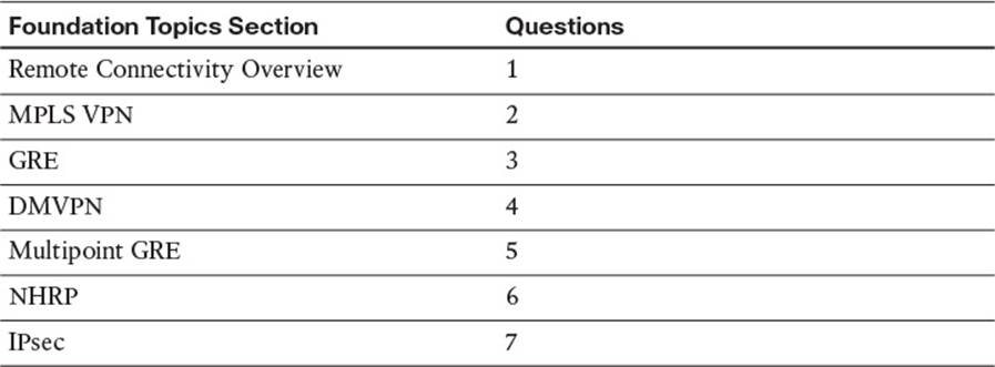
Table 2-1 “Do I Know This Already?” Foundation Topics Section-to-Question Mapping
1. Which of the following is a valid design consideration for a hybrid VPN?
a. You cannot encapsulate an encrypted packet.
b. You cannot encrypt an encapsulated packet.
c. You might need to decrease the MTU size for frames on an interface.
d. You might need to increase the MTU size for frames on an interface.
2. In a Layer 3 MPLS VPN, with what does a CE router form a neighborship?
a. A PE in the MPLS network.
b. A CE at a remote location.
c. No neighborship is formed, because the MPLS network acts as a logical switch.
d. No neighborship is formed, because IP multicast traffic cannot be sent across an MPLS network.
3. You want to interconnect two remote sites with a VPN tunnel. The tunnel needs to support IP unicast, multicast, and broadcast traffic. Additionally, you need to encrypt traffic being sent over the tunnel. Which of the following VPN solutions meets the design requirements?
a. Use a GRE tunnel.
b. Use an IPsec tunnel.
c. Use a GRE tunnel inside of an IPsec tunnel.
d. Use an IPsec tunnel inside of a GRE tunnel.
4. Identify technologies required for a DMVPN network. (Choose three.)
a. NHRP
b. IPsec
c. MPLS
d. mGRE
5. Which of the following are characteristics of multipoint GRE? (Choose two.)
a. mGRE supports a wide variety of protocols.
b. A single mGRE interface can service multiple tunnels.
c. An mGRE interface is created for each tunnel.
d. mGRE only transports unicast IP packets.
6. Which of the following are true for NHRP? (Choose two.)
a. The hub router is configured with the IP addresses of the spoke routers.
b. The spoke routers are configured with the IP address of the hub router.
c. Spoke routers query the hub router asking what tunnel interface IP address corresponds to a known physical interface IP address.
d. Spoke routers query the hub router asking what physical interface IP address corresponds to a known tunnel interface IP address.
7. Which IPsec feature primarily performs encryption?
a. Integrity
b. Confidentiality
c. Antireplay
d. Authentication
Foundation Topics
Remote Connectivity Overview
The voice, video, and data commonly sent between remote offices and central sites often demand low latency and easy provisioning, all while maintaining a low cost. Traditional WAN solutions (for example, leased lines, Frame Relay, and ATM) typically fail to simultaneously meet all these requirements. Fortunately, a variety of VPN technologies fit nicely into such a design.
This section categorizes various VPN technologies. Then, the remainder of this chapter examines these technologies in a bit more detail.
MPLS-Based Virtual Private Networks
Multiprotocol Label Switching (MPLS) is a technology commonly used by service providers, although many large enterprises also use MPLS for their backbone network. MPLS makes forwarding decisions based on labels rather than IP addresses. Specifically, a 32-bit label is inserted between a frame’s Layer 2 and Layer 3 headers. As a result, an MPLS header is often called a shim header, because it is stuck in between two existing headers.
MPLS-based VPNs can be grouped into one of two primary categories:
![]() Layer 2 MPLS VPNs
Layer 2 MPLS VPNs
![]() Layer 3 MPLS VPNs
Layer 3 MPLS VPNs
These two approaches are discussed further in the section “MPLS VPN,” later in this chapter.
Tunnel-Based Virtual Private Networks
A tunnel is a virtual connection that can physically span multiple router hops. However, from the perspective of the traffic flowing through the tunnel, the transit from one end of a tunnel to the other appears to be a single router hop.
Multiple VPN technologies make use of virtual tunnels. A few examples discussed in this chapter include
![]() Generic Routing Encapsulation (GRE)
Generic Routing Encapsulation (GRE)
![]() Dynamic Multipoint VPN (DMVPN)
Dynamic Multipoint VPN (DMVPN)
![]() Multipoint GRE
Multipoint GRE
![]() IPsec
IPsec
Hybrid Virtual Private Networks
Rather than just using a single MPLS-based VPN technology or a single tunnel-based VPN technology, you can use select VPN technologies in tandem. For example, you might want to extend an MPLS network at one corporate location to MPLS networks at remote corporate locations, while having a requirement that traffic traveling through a service provider’s cloud be encrypted.
You could meet the requirements of such a design by having a Layer 3 MPLS VPN set up over a DMVPN. The DMVPN technology carrying the Layer 3 MPLS VPN traffic allows you to efficiently set up direct links between corporate locations, and it also allows you to use IPsec, which can encrypt the traffic flowing through the service provider’s cloud.
When it comes to hybrid VPNs, a significant design consideration is overhead. Every time you add an encapsulation, you are adding to the total header size of the packet. With more headers, the amount of data you can carry inside a single packet is decreased. As a result, you might have to configure a lower maximum transmission unit (MTU) size for frames on an interface.
MPLS VPN
MPLS VPNs extend the capabilities of MPLS, supporting VPNs created across an MPLS network. These VPNs, most commonly found in service provider or large enterprise networks, can be categorized as either Layer 2 MPLS VPNs or Layer 3 MPLS VPNs.
Layer 2 MPLS VPN
With a Layer 2 MPLS VPN, the MPLS network allows customer edge (CE) routers at different sites to form routing protocol neighborships with one another as if they were Layer 2 adjacent. Therefore, you can think of a Layer 2 MPLS VPN as a logical Layer 2 switch, as depicted in Figure 2-1.

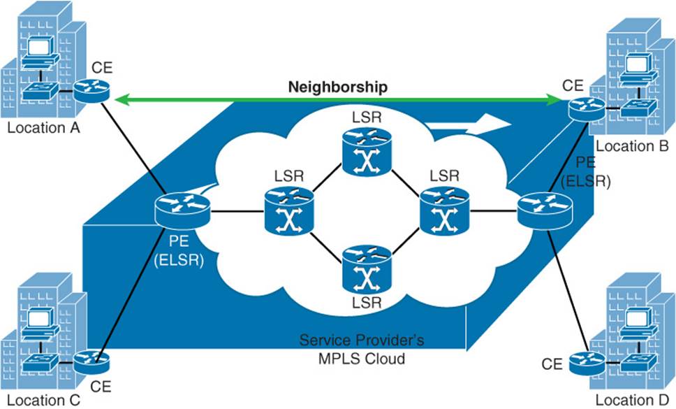
Figure 2-1 Logical View of a Layer 2 MPLS VPN
Layer 3 MPLS VPN
With a Layer 3 MPLS VPN, a service provider’s provider edge (PE) router (also known as an Edge Label Switch Router [ELSR]) establishes a peering relationship with a CE router, as seen in Figure 2-2. Routes learned from the CE router are then sent to the remote PE router in the MPLS cloud (typically using multiprotocol BGP [MP-BGP]), where they are sent out to the remote CE router.
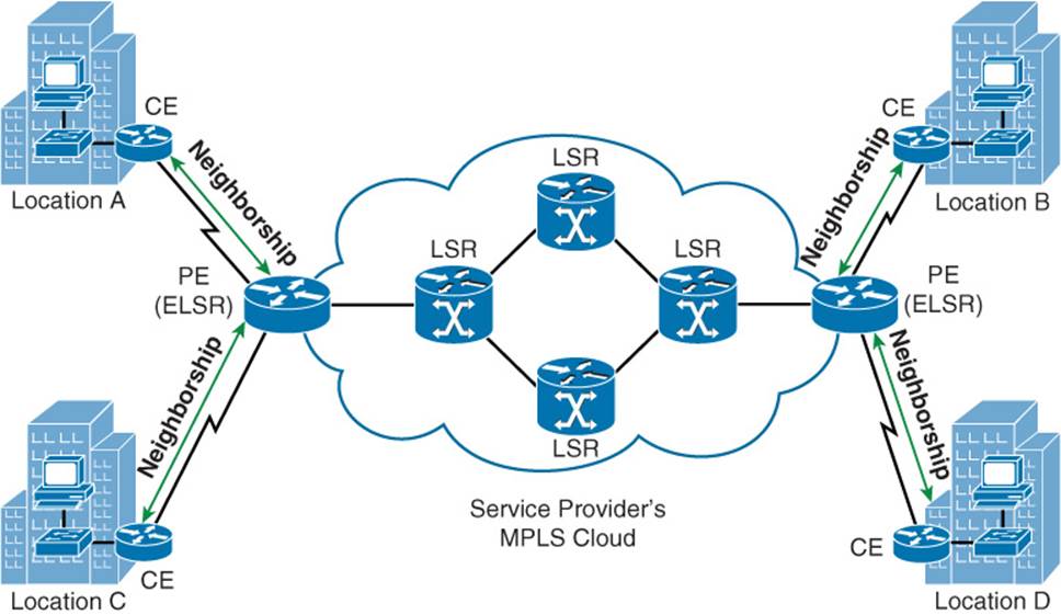
Figure 2-2 Layer 3 MPLS VPN
GRE
As its name suggests, a Generic Routing Encapsulation (GRE) tunnel can encapsulate nearly every type of data that you could send out of a physical router interface. In fact, GRE can encapsulate any Layer 3 protocol, which makes it very flexible.
GRE by itself does not provide any security for the data it transmits; however, a GRE packet can be sent over an IPsec VPN, causing the GRE packet (and therefore its contents) to be protected. Such a configuration is commonly used, because IPsec can only protect unicast IP packets. This limitation causes issues for routing protocols that use IP multicasts. Fortunately, a GRE tunnel can encapsulate IP multicast packets. The resulting GRE packet is an IP unicast packet, which can then be protected by an IPsec tunnel.
As an example, consider Figure 2-3. Routers R1 and R2 need to form an Open Shortest Path First (OSPF) neighborship across the service provider’s cloud. Additionally, traffic between these two routers needs to be protected. While IPsec can protect unicast IP traffic, OSPF communicates through IP multicasts. Therefore, all traffic between Routers R1 and R2 (including the OSPF multicasts) is encapsulated inside of a GRE tunnel. Those GRE packets, which are unicast IP packets, are then sent across, and protected by, an IPsec tunnel.
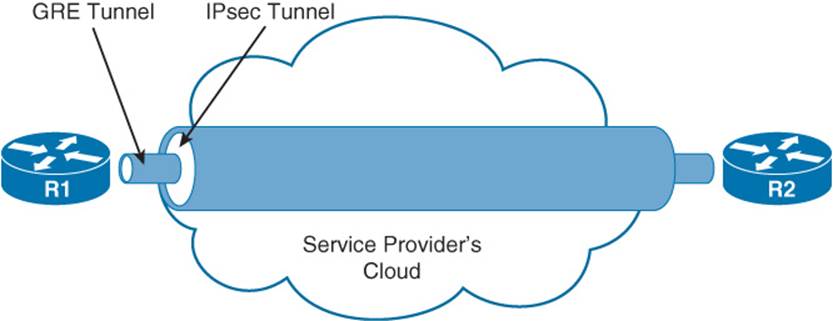
Figure 2-3 GRE over IPsec Tunnel
Note
For exam purposes, the only type of tunnel you need to know how to configure, based on the objectives listed in the ROUTE exam blueprint, is a GRE tunnel. Therefore, this chapter only provides a configuration example for a GRE tunnel.
The steps to configure a GRE tunnel are as follows:
Step 1. Create a virtual tunnel interface in global configuration mode with the interface tunnel id command.
Step 2. In interface configuration mode for the tunnel interface, add an IP address with the ip address ip_address subnet_mask command.
Step 3. Specify the source of the tunnel with the tunnel source {interface_id | ip_address} command.
Step 4. Specify the destination of the tunnel with the tunnel destination ip_address command.
Step 5. Repeat the previous steps on the router at the far side of the tunnel.
To illustrate this configuration procedure, consider Example 2-1 and the topology shown in Figure 2-4.
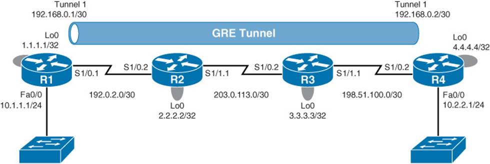
Figure 2-4 GRE Sample Topology
Example 2-1 GRE Sample Configuration
!ROUTER R1
interface Tunnel1
ip address 192.168.0.1 255.255.255.252
tunnel source Loopback0
tunnel destination 4.4.4.4
!ROUTER R4
interface Tunnel1
ip address 192.168.0.2 255.255.255.252
tunnel source Loopback0
tunnel destination 1.1.1.1
In Example 2-1, a virtual tunnel interface is created on Router R1 with the interface Tunnel 1 command. An IP address is then assigned with the ip address 192.168.0.1 255.255.255.252 command. Next, the tunnel source Loopback0 command is used to specify Router R1’s Lo 0 interface (and therefore its IP address of 1.1.1.1) as one end of the GRE tunnel. The tunnel destination 4.4.4.4 command is then used to specify the Lo 0 interface on Router R4 as the other end of the tunnel. A mirrored configuration of the tunnel interface is then entered on Router R4.
Example 2-2 shows verification of the GRE tunnel. In the output of the show interfaces tunnel 1 command, notice that the interface is up at Layer 1 and Layer 2. Also, note that the encapsulation type is TUNNEL. Also, the output of the traceroute 192.168.0.2 command shows that the IP address of 192.168.0.2 is logically a single hop away from Router R1, even though it is physically three hops away.
Example 2-2 GRE Tunnel Verification
R1# show interfaces tunnel 1
Tunnel1 is up, line protocol is up
Hardware is Tunnel
Internet address is 192.168.0.1/30
MTU 17916 bytes, BW 100 Kbit/sec, DLY 50000 usec,
reliability 255/255, txload 1/255, rxload 1/255
Encapsulation TUNNEL, loopback not set
Keepalive not set
Tunnel source 1.1.1.1 (Loopback0), destination 4.4.4.4
Tunnel Subblocks:
src-track:
Tunnel1 source tracking subblock associated with Loopback0
Set of tunnels with source Loopback0, 1 member (includes iterators), on
interface <OK>
Tunnel protocol/transport GRE/IP
Key disabled, sequencing disabled
Checksumming of packets disabled
Tunnel TTL 255, Fast tunneling enabled
Tunnel transport MTU 1476 bytes
Tunnel transmit bandwidth 8000 (kbps)
Tunnel receive bandwidth 8000 (kbps)
Last input 00:00:01, output 00:00:01, output hang never
Last clearing of "show interface" counters 00:54:43
Input queue: 0/75/0/0 (size/max/drops/flushes); Total output drops: 0
Queueing strategy: fifo
Output queue: 0/0 (size/max)
5 minute input rate 0 bits/sec, 0 packets/sec
5 minute output rate 0 bits/sec, 0 packets/sec
779 packets input, 67357 bytes, 0 no buffer
Received 0 broadcasts (0 IP multicasts)
0 runts, 0 giants, 0 throttles
0 input errors, 0 CRC, 0 frame, 0 overrun, 0 ignored, 0 abort
787 packets output, 68037 bytes, 0 underruns
0 output errors, 0 collisions, 0 interface resets
0 unknown protocol drops
0 output buffer failures, 0 output buffers swapped out
R1# traceroute 192.168.0.2
Type escape sequence to abort.
Tracing the route to 192.168.0.2
VRF info: (vrf in name/id, vrf out name/id)
1 192.168.0.2 108 msec 100 msec 108 msec
DMVPN
Consider a hub-and-spoke VPN topology in which multiple remote sites have a site-to-site VPN connection to a headquarters location. In such a topology, if one remote site wanted to communicate securely with another remote site, the traffic would travel between the sites through the headquarters location, rather than directly between the sites. One fix for this suboptimal pathing issue would be to create a full mesh of IPsec site-to-site VPN connections, which would provide a direct IPsec VPN connection between any two remote sites. Such a solution, however, could be complex and expensive to configure and maintain.
A more economical solution to providing optimal pathing without necessitating a full-mesh topology is the Dynamic Multipoint VPN (DMVPN) feature. DMVPN allows a VPN tunnel to be dynamically created and torn down between two remote sites on an as-needed basis. Consider Figure 2-5, which shows a hub-and-spoke topology, with the headquarters acting as the hub. Branch B and Branch C want to communicate with one another. Therefore, a DMVPN tunnel is created between these two locations.
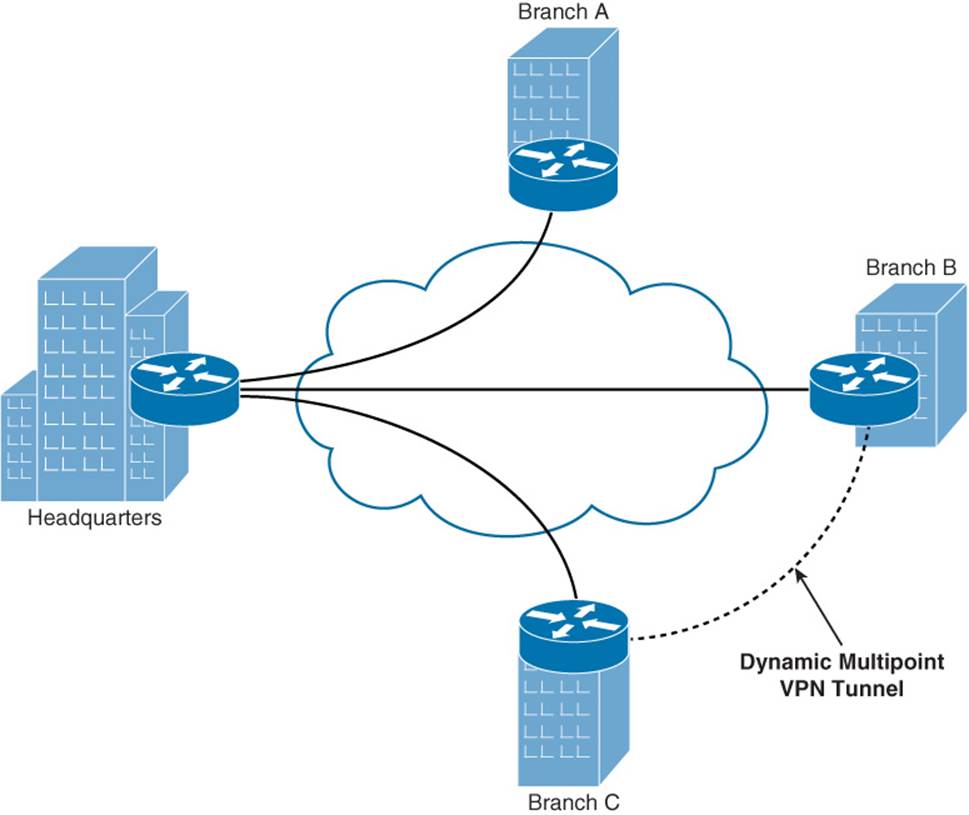
Figure 2-5 Dynamic Multipoint VPN
From a troubleshooting perspective, a common issue experienced with DMVPN networks is flapping (that is, the DMVPN tunnel is repeatedly torn down and reestablished). When experiencing such an issue, Cisco recommends that you check the routing protocol neighborship between the routers at each end of the DMVPN. If the neighborship is not always up, the DMVPN might flap.
Note
Multipoint GRE, Next Hop Resolution Protocol (NHRP), and IPsec are required to support a DMVPN topology. Each of these technologies is discussed in the remainder of this chapter.
Multipoint GRE
The scalability offered by DMVPN is made possible, in part, by multipoint GRE (mGRE), which allows a router to support multiple GRE tunnels on a single GRE interface.
Some of mGRE’s characteristics are as follows:
![]() Like traditional GRE, mGRE can transport a wide variety of protocols (for example, IP unicast, multicast, and broadcast).
Like traditional GRE, mGRE can transport a wide variety of protocols (for example, IP unicast, multicast, and broadcast).
![]() In a hub-and-spoke topology, a hub router can have a single mGRE interface, and multiple tunnels can use that single interface.
In a hub-and-spoke topology, a hub router can have a single mGRE interface, and multiple tunnels can use that single interface.
![]() An interface configured for mGRE is able to dynamically form a GRE tunnel by using Next Hop Resolution Protocol (NHRP) to discover the IP address of the device at the far end of the tunnel.
An interface configured for mGRE is able to dynamically form a GRE tunnel by using Next Hop Resolution Protocol (NHRP) to discover the IP address of the device at the far end of the tunnel.
You can deploy mGRE in a hub-and-spoke topology or a spoke-to-spoke topology. Figure 2-6 illustrates a hub-and-spoke topology, where only the hub router is configured with an mGRE interface.
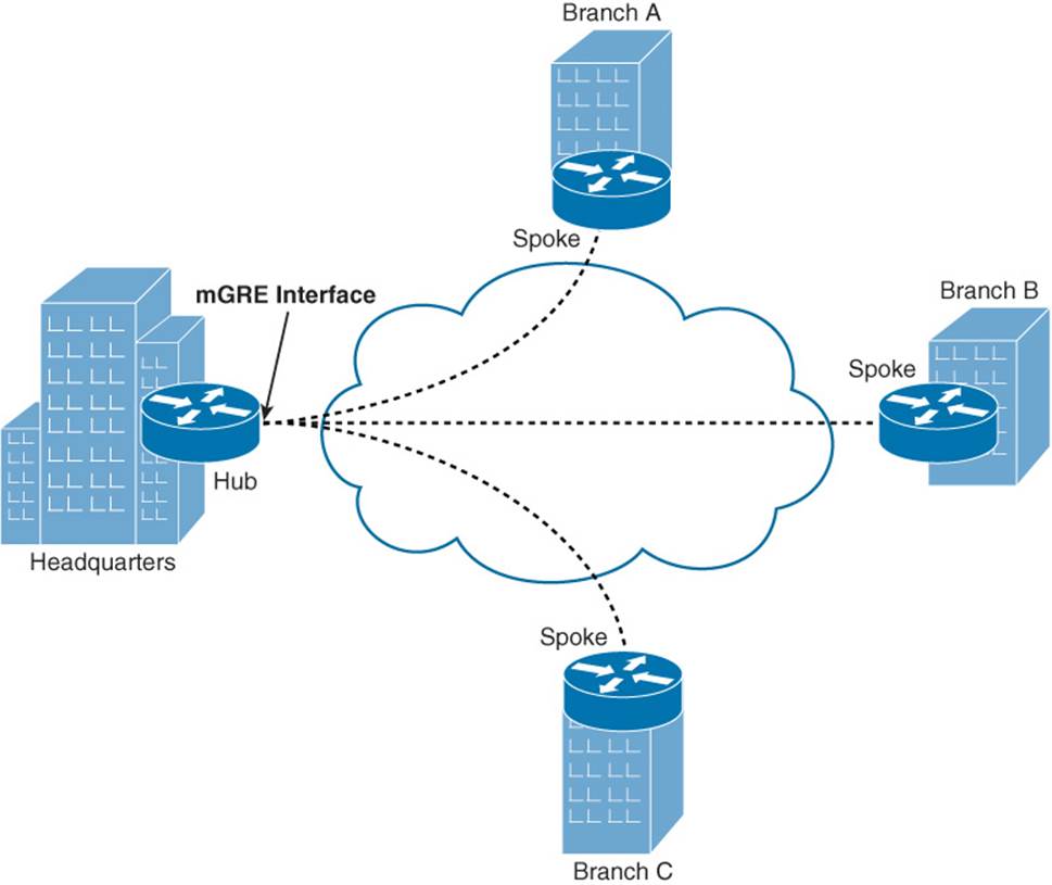
Figure 2-6 Hub-and-Spoke mGRE Tunnel Topology
Figure 2-7 shows a spoke-to-spoke mGRE topology. With a spoke-to-spoke mGRE topology, each router has an mGRE interface, which allows the sites in the network to interconnect using a partial mesh or a full mesh collection of tunnels.
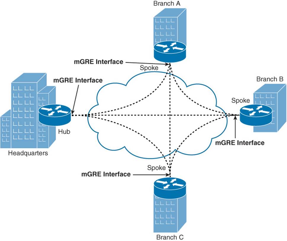
Figure 2-7 Spoke-to-Spoke mGRE Tunnel Topology
NHRP
DMVPNs require that routers run Next Hop Resolution Protocol (NHRP), which uses a client-server model. A router designated as a hub router acts as a server. The remaining routers, designated as spokes, act as clients. NHRP spokes are configured with the IP address of the NHRP hub, and when a spoke comes online, it informs the hub of both a physical IP address (assigned to its physical interface) and a logical IP address (assigned to its virtual tunnel interface) that are going to be used for its tunnels.
As an example, examine Figure 2-8.
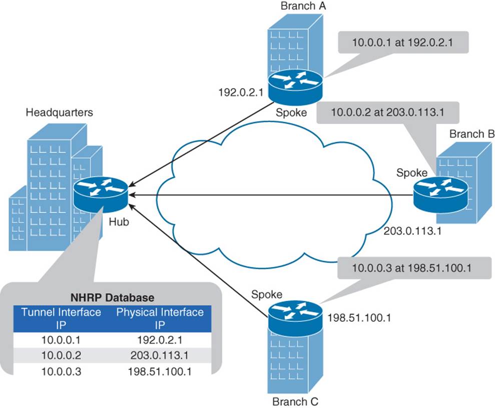
Figure 2-8 NHRP Registration Process
In Figure 2-8, the Headquarters router is acting as the hub, and the Branch A, Branch B, and Branch C routers are acting as spokes. When the spokes come online, they each advertise the IP address of their physical interface that is going to be used for tunnel formation, along with the IP address of the virtual tunnel interface. For example, the Branch A router informs the Headquarters router that the IP address of its virtual tunnel interface is 10.0.0.1, and it is available at a physical interface’s IP address of 192.0.2.1. The Branch B and Branch C routers send similar advertisements to the Headquarters router. As a result, the Headquarters router populates its NHRP database.
Note
The prior description of NHRP used the term physical interface to distinguish a nontunnel interface from a tunnel interface. Realize, however, that an interface being referred to here as a physical interface could actually be a loopback interface.
With the hub’s database populated, a spoke can query the hub to find out the IP address of a physical interface that corresponds to a specific tunnel interface’s IP address. As an example, notice in Figure 2-9 how NHRP helps the Branch C router set up a GRE tunnel with the Branch B router.
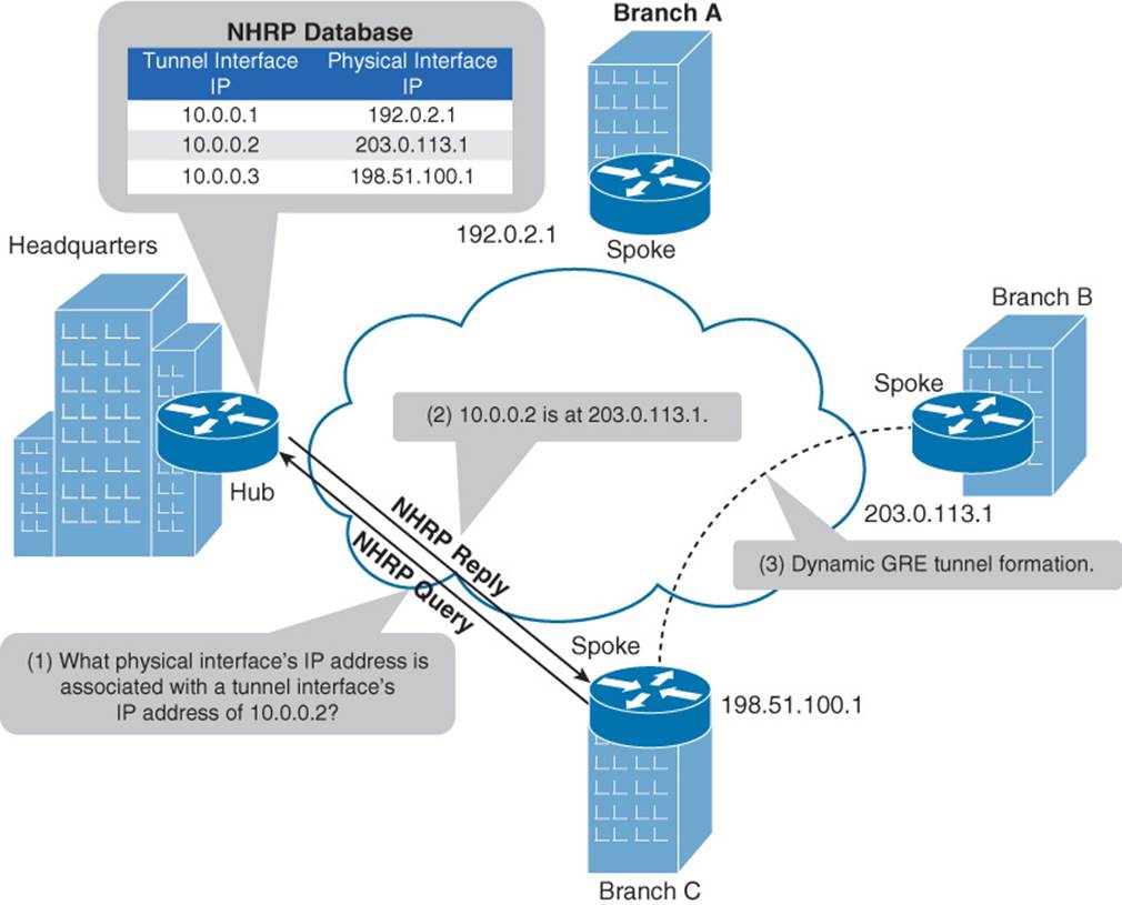
Figure 2-9 NHRP Query Process
In Figure 2-9, the Branch C router needs to dynamically form a GRE tunnel with the Branch B router. The Branch C router knows that the other end of the tunnel it wants to form has an IP address of 10.0.0.2. However, the Branch C router does not know the IP address of the physical interface on the Branch B router that corresponds to the virtual tunnel’s IP address. The process of discovering the remote physical IP address and the formation of the tunnel is as follows:
Step 1. The Branch C router sends an NHRP query to the hub router asking what physical interface’s IP address is associated with a tunnel interface’s IP address of 10.0.0.2.
Step 2. The hub router (that is, the Headquarters router) checks its NHRP database and responds to the query, telling the Branch C router that the physical interface’s IP address corresponding to the tunnel interface IP address of 10.0.0.2 is 203.0.113.1, which is the IP address of the Branch B router.
Step 3. Having dynamically learned the IP address of the physical interface in the Branch B router, the Branch C router sets up a GRE tunnel with the Branch B router.
While the configuration of NHRP is beyond the scope of the ROUTE curriculum, you should be familiar with the output of the show ip nhrp verification command. Example 2-3 shows sample output from this command.
Example 2-3 Sample Output from the show ip nhrp Command
Router# show ip nhrp
192.168.0.2 255.255.255.255, tunnel 100 created 0:00:44 expire 1:59:15
Type: dynamic Flags: authoritative
NBMA address: 10.1111.1111.1111.1111.1111.1111.1111.1111.1111.11
192.168.0.1 255.255.255.255, Tunnel10 created 0:10:04 expire 1:49:56
Type: static Flags: authoritative
NBMA address: 192.168.1.2
The output in Example 2-3 shows the IP addresses (and corresponding subnet masks) in the IP-to-NBMA address cache. Note that the subnet mask for an IP address is always a /32 mask, because the Cisco implementation of NHRP does not support the aggregation of nonbroadcast multiaccess (NBMA) information. The output also shows the tunnel interface name and how long it has been since the tunnel was created. Finally, notice the authoritative flag. This flag indicates that a next-hop server (or router) provided the NHRP information.
IPsec
Security in a DMVPN is provided by IPsec. The following four security features are offered by IPsec:
![]() Confidentiality: Data confidentiality is provided by encrypting data. If a third party intercepts the encrypted data, the party would not be able to interpret the data.
Confidentiality: Data confidentiality is provided by encrypting data. If a third party intercepts the encrypted data, the party would not be able to interpret the data.
![]() Integrity: Data integrity ensures that data is not modified in transit. For example, routers at each end of a tunnel could calculate a checksum value or a hash value for the data, and if both routers calculate the same value, the data has most likely not been modified in transit.
Integrity: Data integrity ensures that data is not modified in transit. For example, routers at each end of a tunnel could calculate a checksum value or a hash value for the data, and if both routers calculate the same value, the data has most likely not been modified in transit.
![]() Authentication: Data authentication allows parties involved in a conversation to verify that the other party is the party it claims to be.
Authentication: Data authentication allows parties involved in a conversation to verify that the other party is the party it claims to be.
![]() Antireplay: IPsec uses antireplay protection to ensure that packets being sent are not duplicate packets. For example, an attacker might capture packets that make up a valid login to a host and attempt to play those packets back, so that he can gain access to the host. However, IPsec uses sequence numbers to determine whether a packet is to be considered a duplicate packet, and any duplicate packets are not transmitted.
Antireplay: IPsec uses antireplay protection to ensure that packets being sent are not duplicate packets. For example, an attacker might capture packets that make up a valid login to a host and attempt to play those packets back, so that he can gain access to the host. However, IPsec uses sequence numbers to determine whether a packet is to be considered a duplicate packet, and any duplicate packets are not transmitted.
Of these IPsec services, encryption and authentication are particularly helpful in a DMVPN network. For example, encryption can help protect traffic flowing between sites (either over the Internet or through a service provider’s cloud). Also, authentication can make sure that GRE tunnels are not dynamically set up with undesired spokes.
IPsec uses a collection of protocols to provide its features. One of the primary protocols used by IPsec is the Internet Key Exchange (IKE) protocol. Specifically, IPsec can provide encryption between authenticated peers using encryption keys, which are periodically changed. IKE does, however, allow an administrator to manually configure keys.
There are two phases to establish an IPsec tunnel. During IKE Phase 1, a secure Internet Security Association and Key Management Protocol (ISAKMP) session is established. As part of this phase, the IPsec endpoints establish transform sets (that is, a collection of encryption and authentication protocols), hash methods, and other parameters needed to establish a secure ISAKMP session (sometimes called an ISAKMP tunnel or an IKE Phase 1 tunnel). This collection of parameters is called a security association (SA). With IKE Phase 1, the SA is bidirectional, meaning that the same key exchange is used for data flowing across the tunnel in either direction.
IKE Phase 2 occurs within the protection of an IKE Phase 1 tunnel. A session formed during IKE Phase 2 is sometimes called an IKE Phase 2 tunnel, or simply an IPsec tunnel. However, unlike IKE Phase 1, IKE Phase 2 performs unidirectional SA negotiations, meaning that each data flow uses a separate key exchange.
In addition to IKE, which establishes the IPsec tunnel, IPsec also relies on either the Authentication Header (AH) protocol (IP protocol number 51) or the Encapsulating Security Payload (ESP) protocol (IP protocol number 50). Both AH and ESP offer origin authentication and integrity services, which ensure that IPsec peers are who they claim to be and that data was not modified in transit.
The main distinction between AH and ESP, however, is encryption support. ESP encrypts the original packet, while AH does not offer any encryption. As a result, ESP is far more popular on today’s networks.
Both AH and ESP can operate in one of two modes, transport mode or tunnel mode. Figure 2-10 illustrates the structure of an ESP transport mode packet versus an ESP tunnel mode packet.
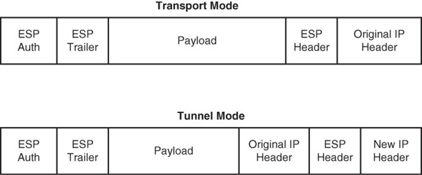
Figure 2-10 Transport Mode Versus Tunnel Mode
Following is a detailed description of these two modes:
![]() Transport Mode: Transport mode uses a packet’s original IP header, as opposed to adding an additional tunnel header. This approach works well in networks where increasing a packet’s size could cause an issue. Also, transport mode is frequently used for client-to-site VPNs, where a PC running VPN client software connects back to a VPN termination device at a headquarters location.
Transport Mode: Transport mode uses a packet’s original IP header, as opposed to adding an additional tunnel header. This approach works well in networks where increasing a packet’s size could cause an issue. Also, transport mode is frequently used for client-to-site VPNs, where a PC running VPN client software connects back to a VPN termination device at a headquarters location.
![]() Tunnel Mode: Tunnel mode, unlike transport mode, encapsulates an entire packet. As a result, the encapsulated packet has a new header (that is, an IPsec header). This new header has source and destination IP address information that reflects the two VPN termination devices at different sites. Therefore, tunnel mode is frequently used in an IPsec site-to-site VPN.
Tunnel Mode: Tunnel mode, unlike transport mode, encapsulates an entire packet. As a result, the encapsulated packet has a new header (that is, an IPsec header). This new header has source and destination IP address information that reflects the two VPN termination devices at different sites. Therefore, tunnel mode is frequently used in an IPsec site-to-site VPN.
The process of establishing, maintaining, and tearing down an IPsec site-to-site VPN consists of five primary steps, as illustrated in Figure 2-11 and described in the list that follows.
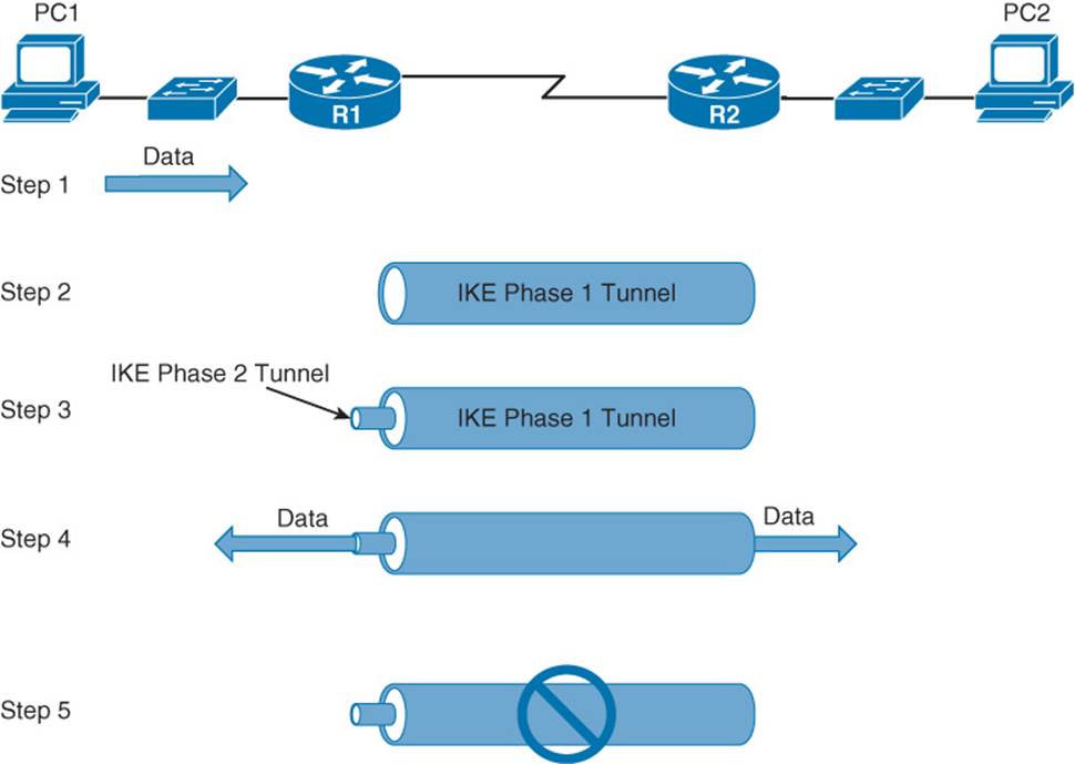
Figure 2-11 IPsec VPN Steps
Step 1. PC1 sends traffic destined for PC2. Router1 classifies the traffic as “interesting” traffic, which initiates the creation of an IPsec tunnel.
Step 2. Router1 and Router2 negotiate a security association (SA) used to form an IKE Phase 1 tunnel, which is also known as an ISAKMP tunnel.
Step 3. Within the protection of the IKE Phase 1 tunnel, an IKE Phase 2 tunnel is negotiated and set up. An IKE Phase 2 tunnel is also known as an IPsec tunnel.
Step 4. After the IPsec tunnel is established, interesting traffic (for example, traffic classified by an ACL) flows through the protected IPsec tunnel. Note that traffic not deemed interesting can still be sent between PC1 and PC2. However, the noninteresting traffic is transmitted outside of the protection of the IPsec tunnel.
Step 5. After no interesting traffic has been seen for a specified amount of time, or if the IPsec SA is deleted, the IPsec tunnel is torn down.
Even though the configuration of IPsec is beyond the scope of the ROUTE curriculum, you should be familiar with the output of the show crypto ipsec sa command, which lets you see information about the SA negotiated between IPsec peers. Example 2-4 shows sample output from this command.
Example 2-4 Sample Output from the show crypto ipsec sa Command
R1# show crypto ipsec sa
interface: FastEthernet0/0
Crypto map tag: test, local addr. 30.1.1.1
local ident (addr/mask/prot/port): (20.1.1.0/255.255.255.0/0/0)
remote ident (addr/mask/prot/port): (10.1.1.0/255.255.255.0/0/0)
current_peer: 30.1.1.2
PERMIT, flags={origin_is_acl,}
#pkts encaps: 7647918, #pkts encrypt: 7647918, #pkts digest 7647918
#pkts decaps: 7640382, #pkts decrypt: 7640382, #pkts verify 7640382
#pkts compressed: 0, #pkts decompressed: 0
#pkts not compressed: 0, #pkts compr. failed: 0,
#pkts decompress failed: 0, #send errors 1, #recv errors 0
local crypto endpt.: 30.1.1.1, remote crypto endpt.: 30.1.1.2
path mtu 1500, media mtu 1500
current outbound spi: 3D3
inbound esp sas:
spi: 0x136A010F(325714191)
transform: esp-3des esp-md5-hmac ,
in use settings ={Tunnel, }
slot: 0, conn id: 3442, flow_id: 1443, crypto map: test
sa timing: remaining key lifetime (k/sec): (4608000/52)
IV size: 8 bytes
replay detection support: Y
inbound ah sas:
inbound pcp sas:
inbound pcp sas:
outbound esp sas:
spi: 0x3D3(979)
transform: esp-3des esp-md5-hmac ,
in use settings ={Tunnel, }
slot: 0, conn id: 3443, flow_id: 1444, crypto map: test
sa timing: remaining key lifetime (k/sec): (4608000/52)
IV size: 8 bytes
replay detection support: Y
outbound ah sas:
outbound pcp sas:
In Example 2-4, an IPsec tunnel is formed between 30.1.1.1 and 30.1.1.2. The tunnel goes between networks 10.1.1.0 /24 and 20.1.1.0 /24. An ACL is used to identify (that is, permit) traffic that should be sent over the IPsec tunnel. Encapsulating Security Payload (ESP) or Triple Data Encryption Standard (3DES) is being used for encryption, and Message Digest 5 (MD5) is used for authentication.
Exam Preparation Tasks
Planning Practice
The CCNP ROUTE exam expects test takers to review design documents, create implementation plans, and create verification plans. This section provides some exercises that can help you to take a step back from the minute details of the topics in this chapter so that you can think about the same technical topics from the planning perspective.
For each planning practice table, simply complete the table. Note that any numbers in parentheses represent the number of options listed for each item in the solutions in Appendix F, “Completed Planning Practice Tables.”
Design Review Table
Table 2-2 lists several design goals related to this chapter. If these design goals were listed in a design document, and you had to take that document and develop an implementation plan, what implementation options come to mind? For any configuration items, a general description can be used, without concern about the specific parameters.
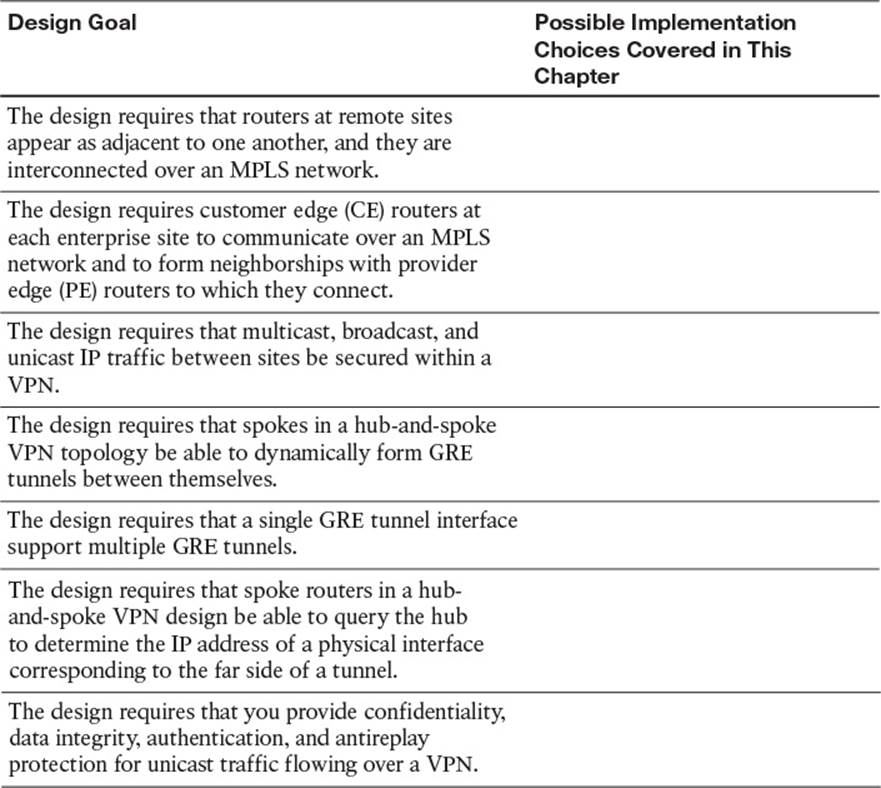
Table 2-2 Design Review
Implementation Plan Peer Review Table
Table 2-3 shows a list of questions that others might ask, or that you might think about, during a peer review of another network engineer’s implementation plan. Complete the table by answering the questions.
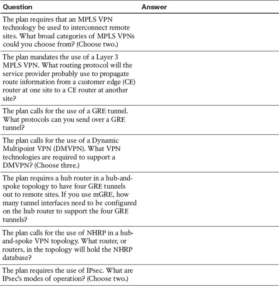
Table 2-3 Notable Questions from This Chapter to Consider During an Implementation Plan Peer Review
Create an Implementation Plan Table
To practice skills useful when creating your own OSPF implementation plan, list in Table 2-4 configuration commands related to the configuration of the following features. You might want to record your answers outside the book, and set a goal to complete this table (and others like it) from memory during your final reviews before taking the exam.
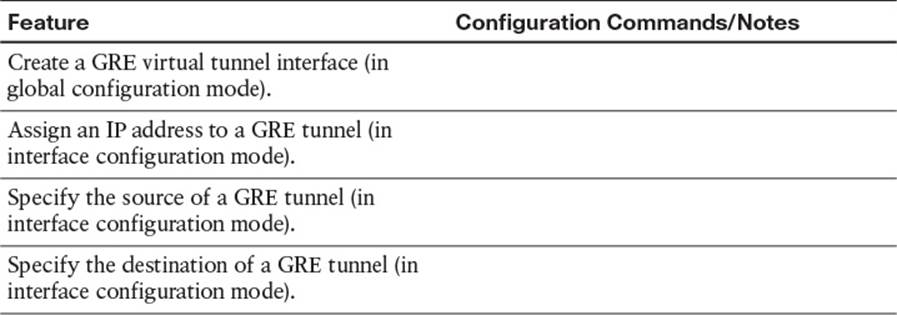
Table 2-4 Implementation Plan Configuration Memory Drill
Choose Commands for a Verification Plan Table
To practice skills useful when creating your own OSPF verification plan, list in Table 2-5 all commands that supply the requested information. You might want to record your answers outside the book, and set a goal to complete this table (and others like it) from memory during your final reviews before taking the exam.
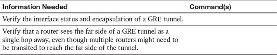
Table 2-5 Verification Plan Memory Drill
Review All the Key Topics
Review the most important topics from inside the chapter, noted with the Key Topics icon in the outer margin of the page. Table 2-6 lists a reference of these key topics and the page numbers on which each is found.
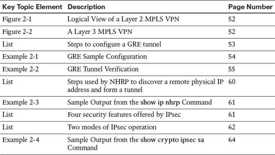
Table 2-6 Key Topics for Chapter 2
Complete the Tables and Lists from Memory
Print a copy of Appendix D, “Memory Tables,” (found on the CD) or at least the section for this chapter, and complete the tables and lists from memory. Appendix E, “Memory Tables Answer Key,” also on the CD, includes completed tables and lists to check your work.
Define Key Terms
Define the following key terms from this chapter, and check your answers in the glossary:
GRE
DMVPN
mGRE
NHRP
IPsec
All materials on the site are licensed Creative Commons Attribution-Sharealike 3.0 Unported CC BY-SA 3.0 & GNU Free Documentation License (GFDL)
If you are the copyright holder of any material contained on our site and intend to remove it, please contact our site administrator for approval.
© 2016-2026 All site design rights belong to S.Y.A.